

Page 1
PART #A208273
LIFESTOR®Shelving
ASSEMBLY INSTRUCTIONS
CAUTION
INSPECT CONTENTS IMMEDIATELY AND FILE CLAIM WITH DELIVERING CARRIER FOR ANY DAMAGE.
SAVE YOUR BOX AND ALL PACKING MATERIALS.
YOU ARE RESPONSIBLE FOR DAMAGE TO YOUR UNIT IF RETURNED IMPROPERLY PACKED.
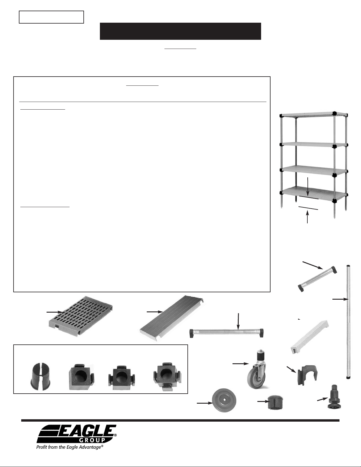
Parts List
model # solid shelf louvered side braces rails connector parts number of
Starter Unit Per Shelf (comes with 4-way connectors)
S1824PM or S2324PM . . . . . . . 2 . . . . . . . . . . . . . . . . . . . . . 2 . . . . . . . . (2) 1813⁄16˝ . . . . . . . . . . . 4 . . . . . . . . . . . . . . 4
S1830PM or S2330PM . . . . . . . 3 . . . . . . . . . . . . . . . . . . . . . 2 . . . . . . . . (2) 261⁄4˝ . . . . . . . . . . . . 4 . . . . . . . . . . . . . . 4
S1836PM or S2336PM . . . . 3 + filler . . . . . . . . . . . . . . . . . . 2 . . . . . . . . (2) 30
S1842PM or S2342PM . . . . . . . 4 . . . . . . . . . . . . . . . . . . . . . 2 . . . . . . . . (2) 3613⁄16˝ . . . . . . . . . . . 4 . . . . . . . . . . . . . . 4
S1848PM or S2348PM . . . . . . . 5 . . . . . . . . . . . . . . . . . . . . . 2 . . . . . . . . (2) 4313⁄16˝ . . . . . . . . . . . 4 . . . . . . . . . . . . . . 4
S1854PM or S2354PM . . . . 5 + filler . . . . . . . . . . . . . . . . . . 2 . . . . . . . . (2) 4813⁄16˝ . . . . . . . . . . . 4 . . . . . . . . . . . . . . 4
S1860PM or S2360PM . . . . . . . 6 . . . . . . . . . . . . . . . . . . . . . 2 . . . . . . . . (2) 5413⁄16˝ . . . . . . . . . . . 4 . . . . . . . . . . . . . . 4
L1824PM or L2324PM . . . . . . . . . . . . . . . . . . 2 . . . . . . . . . . 2 . . . . . . . . (2) 18
L1830PM or L2330PM . . . . . . . . . . . . . . . . . . 3 . . . . . . . . . . 2 . . . . . . . . (2) 261⁄4˝ . . . . . . . . . . . . 4 . . . . . . . . . . . . . . 4
L1836PM or L2336PM . . . . . . . . . . . . . . . 3 + filler . . . . . . . 2 . . . . . . . . (2) 3013⁄16˝ . . . . . . . . . . . 4 . . . . . . . . . . . . . . 4
L1842PM or L2342PM . . . . . . . . . . . . . . . . . . 4 . . . . . . . . . . 2 . . . . . . . . (2) 3613⁄16˝ . . . . . . . . . . . 4 . . . . . . . . . . . . . . 4
L1848PM or L2348PM . . . . . . . . . . . . . . . . . . 5 . . . . . . . . . . 2 . . . . . . . . (2) 43
L1854PM or L2354PM . . . . . . . . . . . . . . . 5 + filler . . . . . . . 2 . . . . . . . . (2) 4813⁄16˝ . . . . . . . . . . . 4 . . . . . . . . . . . . . . 4
L1860PM or L2360PM . . . . . . . . . . . . . . . . . . 6 . . . . . . . . . . 2 . . . . . . . . (2) 5413⁄16˝ . . . . . . . . . . . 4 . . . . . . . . . . . . . . 4
sections shelf sections qty & length lug & split sleeve post per unit
13
⁄16˝ . . . . . . . . . . . 4 . . . . . . . . . . . . . . 4
13
⁄16˝ . . . . . . . . . . . 4 . . . . . . . . . . . . . . 4
13
⁄16˝ . . . . . . . . . . . 4 . . . . . . . . . . . . . . 4
Add-On Units Per Shelf (comes with U-connectors)
AS1824PM or AS2324PM . . . . 2 . . . . . . . . . . . . . . . . . . . . . 1 . . . . . . . . (2) 1813⁄16˝ . . . . . . . . . . . 2 . . . . . . . . . . . . . . 2
AS1830PM or AS2330PM . . . . 3 . . . . . . . . . . . . . . . . . . . . . 1 . . . . . . . . (2) 261⁄4˝ . . . . . . . . . . . . 2 . . . . . . . . . . . . . . 2
AS1836PM or AS2336PM. . 3 + filler . . . . . . . . . . . . . . . . . . 1 . . . . . . . . (2) 3013⁄16˝ . . . . . . . . . . . 2 . . . . . . . . . . . . . . 2
AS1842PM or AS2342PM . . . . 4 . . . . . . . . . . . . . . . . . . . . . 1 . . . . . . . . (2) 3613⁄16˝ . . . . . . . . . . . 2 . . . . . . . . . . . . . . 2
AS1848PM or AS2348PM . . . . 5 . . . . . . . . . . . . . . . . . . . . . 1 . . . . . . . . (2) 43
AS1854PM or AS2354PM. . 5 + filler . . . . . . . . . . . . . . . . . . 1 . . . . . . . . (2) 4813⁄16˝ . . . . . . . . . . . 2 . . . . . . . . . . . . . . 2
AS1860PM or AS2360PM . . . . 6 . . . . . . . . . . . . . . . . . . . . . 1 . . . . . . . . (2) 5413⁄16˝ . . . . . . . . . . . 2 . . . . . . . . . . . . . . 2
AL1824PM or AL2324PM . . . . . . . . . . . . . . . 2 . . . . . . . . . . 1 . . . . . . . . (2) 1813⁄16˝ . . . . . . . . . . . 2 . . . . . . . . . . . . . . 2
AL1830PM or AL2330PM . . . . . . . . . . . . . . . 3 . . . . . . . . . . 1 . . . . . . . . (2) 26
AL1836PM or AL2336PM . . . . . . . . . . . . . 3 + filler . . . . . . . 1 . . . . . . . . (2) 3013⁄16˝ . . . . . . . . . . . 2 . . . . . . . . . . . . . . 2
AL1842PM or AL2342PM . . . . . . . . . . . . . . . 4 . . . . . . . . . . 1 . . . . . . . . (2) 3613⁄16˝ . . . . . . . . . . . 2 . . . . . . . . . . . . . . 2
AL1848PM or AL2348PM . . . . . . . . . . . . . . . 5 . . . . . . . . . . 1 . . . . . . . . (2) 4313⁄16˝ . . . . . . . . . . . 2 . . . . . . . . . . . . . . 2
AL1854PM or AL2354PM . . . . . . . . . . . . . 5 + filler . . . . . . . 1 . . . . . . . . (2) 48
AL1860PM or AL2360PM . . . . . . . . . . . . . . . 6 . . . . . . . . . . 1 . . . . . . . . (2) 5413⁄16˝ . . . . . . . . . . . 2 . . . . . . . . . . . . . . 2
Louvered Shelf
Section
Solid Shelf
Section
13
⁄16˝ . . . . . . . . . . . 2 . . . . . . . . . . . . . . 2
1
⁄4˝ . . . . . . . . . . . . 2 . . . . . . . . . . . . . . 2
13
⁄16˝ . . . . . . . . . . . 2 . . . . . . . . . . . . . . 2
Rail (left to
right support)
Connector Kit:
Split Sleeve
2-Sided Lug 3-Sided Lug
4-Sided Lug
Caster
Minimize vertical height of bottom
shelf from finished floor
for best weight support.
Metal
Side Brace
(used for mobile
application)
Post
Polymer
Side Brace
(used for
stationary
application)
U Connector
Optional Rotary Bumper
Cap
EG9828 Revised 11/08
• 100 Industrial Boulevard, Clayton, Delaware 19938-8903 U.S.A. • www.eaglegrp.com
• Phone: 302/653-3000 • (Foodservice) 800/441-8440 • (MHC/Retail) 800/637-5100
• Fax: 302/653-2065
Eagle Foodservice Equipment, Eagle MHC, SpecFAB®, and Retail Display are divisions of Eagle Group. ©2008 by the Eagle Group
Adjustable
Foot
Page 2
PART #A208273
LIFESTOR®Shelving
ASSEMBLY INSTRUCTIONS
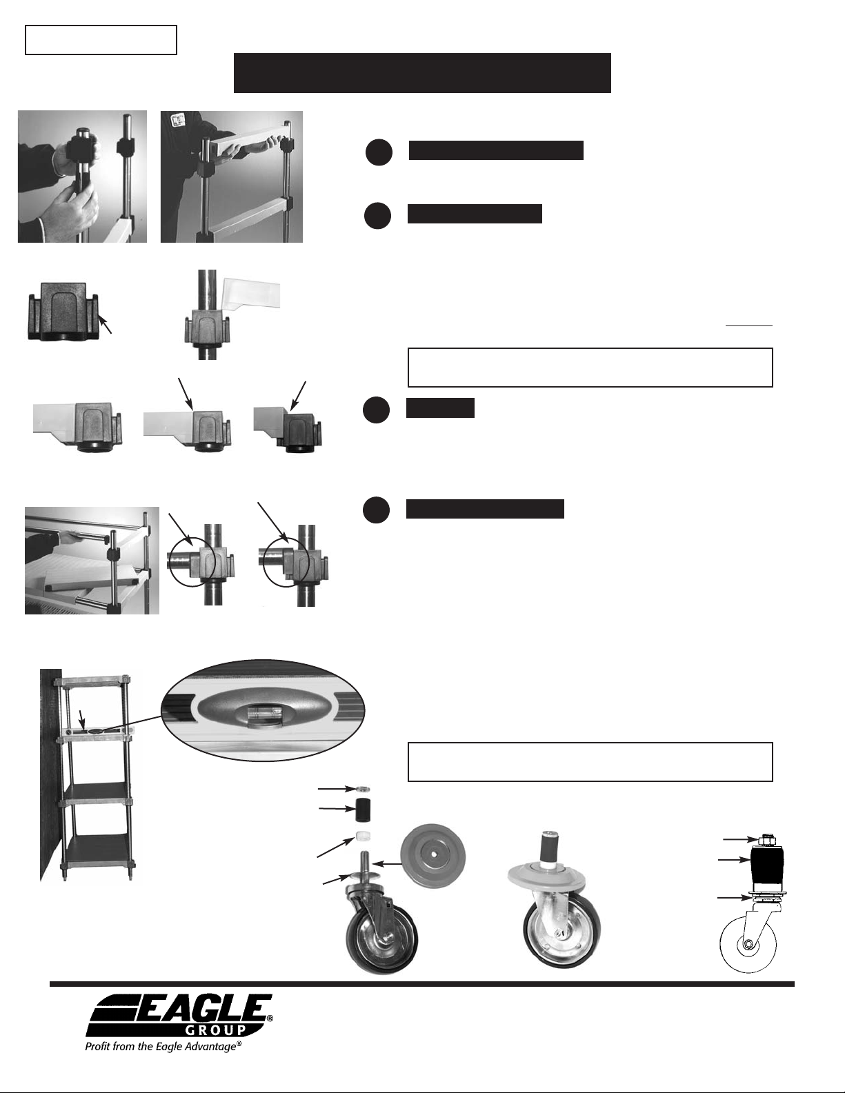
First determine the spacing of the shelf levels. The posts are grooved on
increments to facilitate alignment.
figure 1
figure 2a
figure 2c
figure 3
level (tool)
side
connector
figure 2 (stationary unit shown)
figure 2b
figure 2d
correct
figure 3a
correct
figure 2e
incorrect
figure 3b
incorrect
1
Lug Connectors
Place split sleeve on appropriate groove, then slip lug over split
sleeve. See figure 1.
2
Side Braces
Attach side braces between posts to create “ladder” by sliding the
side brace down onto the side connector of the lug until it is flush.
See figure 2, 2a, 2b and 2c. Ensure that side connector of the lug is
flush with the bottom of side brace by tapping gently with rubber
mallet. See correct and incorrect figures 2d and 2e.
NOTE: THIS ASSEMBLY MUST BE COMPLETED BEFORE
ATTACHING RAILS.
CAUTION: Stationary units use polymer side braces, and mobile
units use metal side braces.
3
Rails
Attach rails between ladders to complete frame structure. See figure
3. Ensure that rail is flush with the bottom of the side connector by
tapping gently with rubber mallet. See correct and incorrect figures
3a and 3b.
4
Shelf Sections
For Stationary Applications:
Place shelf sections on front and rear rails. At the installed location,
utilize front leveling feet to pitch shelving to the rear when mounted
against a wall. See figure 4 - an example of unit placed against a
wall and slightly pitched.
For Mobile Applications:
Caster Assembly: Assemble caster and optional rotary bumper per
figures 5 and 6. Install into post by tightening top nut until
applicator starts to expand. Insert caster into leg. If it does not fit
snug, tighten top nut again. When caster is tight in leg, tighten
bottom nut. See figure 7.
Place shelf sections on front and rear rails.
NOTE: 4-shelf
unit minimum
per stationary
or mobile units.
shelving unit pitched
(exaggerated for illustrative purposes)
figure 4
Eagle Foodservice Equipment, Eagle MHC, SpecFAB®, and Retail Display are divisions of Eagle Group. ©2008 by the Eagle Group
CAUTION: Stainless steel or zinc side braces are required for use
with casters.
nut
rubber
expansion
applicator
white sleeve
metal washer
figure 5
rotary
bumper
figure 6
caster shown
with optional
rotary bumper
bottom nut
• 100 Industrial Boulevard, Clayton, Delaware 19938-8903 U.S.A. • www.eaglegrp.com
• Phone: 302/653-3000 • (Foodservice) 800/441-8440 • (MHC/Retail) 800/637-5100
• Fax: 302/653-2065
top nut
rubber
expansion
applicator
figure 7
 Loading...