

Page 1
AccuNav
II
INSTALLATION
INSTRUCTIONS
LITHO IN U.S.A.
PDF compression, OCR, web-optimization with CVISION's PdfCompressor
988-0129-18
EAGI
AND OPERATION
Page 2
USE THIS GPS
CAREFUL NAVIGATOR
OBTAIN POSITION
This GPS
shortest,
waypoint regardless
not
a
waypoint,
the
As of
GPS
Satellites can betumed off
operators.
most
take
only
waypoint
this
writing,
navigation system operational.
Remember that the AccuNav
accurate as the
RECEIVER ONLY AS AN AID TO
receiver,
direct
advantage
but
will also
is
always
the
systei
INFORMATION.
(like
path
of obstructions.
of all available
visually
available.
Department
it's
WARNING!
NAVIGATION. A
NEVER RELIES ON ONLY ONE
CAUTION
all GPS
to a
oraccuracycan
using.
navigation
waypoint.
Therefore,
navigation
check to make certain a
It
provides
equipment)
navigation
the
tools when
NOTICE!
of Defense
The
(DOD)
system
bedegraded
II,
is still in a
or
GPS receiver is
any
prudent
clear,
has not declared the
atwill
METHOD TO
will show the
data to the
path
only
will
to
to
as
navigator
travelling
safe
testing phase.
bythesystem
NOTES:
All
features and
Copyright0
specifications subject
All
1993
rights
Electronics
Eagle
reserved.
to
change
without
notice.
All screens in this manual are simulated.
PDF compression, OCR, web-optimization with CVISION's PdfCompressor
Page 3
ALARM
OF CONTENTS
1
2
3
6
7
S
S
9
10
10
10
11
II
12
12
13
14
15
15
16
17
17
IS
IS
IS
19
19
19
19
20
20
20
21
21
22
22
22
23
23
24
25
25
26
26
26
27
27
28
28
29
29
30
30
31
32
32
33
33
35
35
35
35
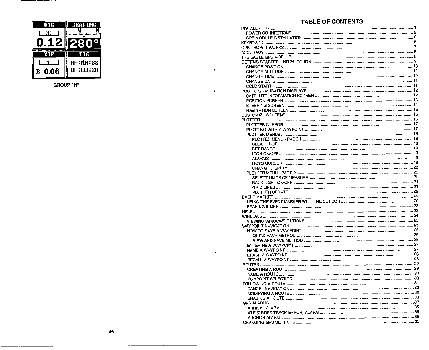
Mp •:jj?IIlfl[eI
MI I
I
012
I MI I
B
006
GROUP
(ii N
,pj4n,u, Ipumó pip,p'
In,,,, I'
:
HH:MM:SS
00:00:20
"H"
TABLE
INSTALLATION
KEYBOARD
GPS-HOWITWORKS
ACCURACY
THE
GETTING STARTED - INITIALIZATION
POSITION/NAVIGATION
CUSTOMIZE
PLOTTER
EVENT MARKER
HELP
WINDOWS
WAYPOINT NAVIGATION
ROUTES
FOLLOWING A ROUTE
GPS ALARMS
CHANGING GPS SETTINGS
CONNECTIONS
POWER
GPS MODULE INSTALLATION
EAGLE GPS MODULE
CHANGE POSITION
CHANGEALTITUDE
CHANGE TIME
CHANGEDATE
COLD START
SATELLITE INFORMATION SCREEN
POSITION
STEERING SCREEN
NAVIGATION SCREEN
PLOTTER
PLOTTING WITH A WAYPOINT
PLOTTER MENUS
PLOTTER MENU
USING THE EVENT MARKER
ERASING ICONS
VIEWING WINDOWS
HOW
SCREEN
SCREENS
CURSOR
PLOTTER
CLEAR PLOT
SETRANGE
ICON ON/OFF
ALARMS
GOTO CURSOR
CHANGE DISPLAY
SELECT UNITS OF MEASURE
BACK LIGHT ON/OFF
GRID LINES
PLOTTER UPDATE
TO SAVE A WAYPOINT
MENU
-
DISPLAYS
.
PAGE 1
PAGE 2
OPTIONS
WITH THE CURSOR
QUICK SAVE METHOD
VIEW AND SAVE METHOD
ENTER NEW WAYPOINT
NAMEAWAYPOINT
ERASE A WAYPOINT
RECALL A WAYPOINT
CREATING A ROUTE
NAMEAROUTE
WAYPOINT SELECTION
CANCEL
MODIFYING A ROUTE
ERASING A ROUTE
ARRIVAL ALARM
XTE
ANCHOR ALARM
NAVIGATION
(CROSS
TRACK
ERROR)
46
PDF compression, OCR, web-optimization with CVISION's PdfCompressor
Page 4
TABLE
SELECT NMENDGPS RECEIVER
TRUE AND MAGNETIC POSITION
PRESET
MAN OVERBOARD
PCF OFFSET
OPS MODULE SELF-TEST
GPS SIMULATOR
SPECIFICATIONS
WINDOWS
SUMMARY
OF CONTENTS
(cant.)
36
38
39
39
41
'13
c
44
45
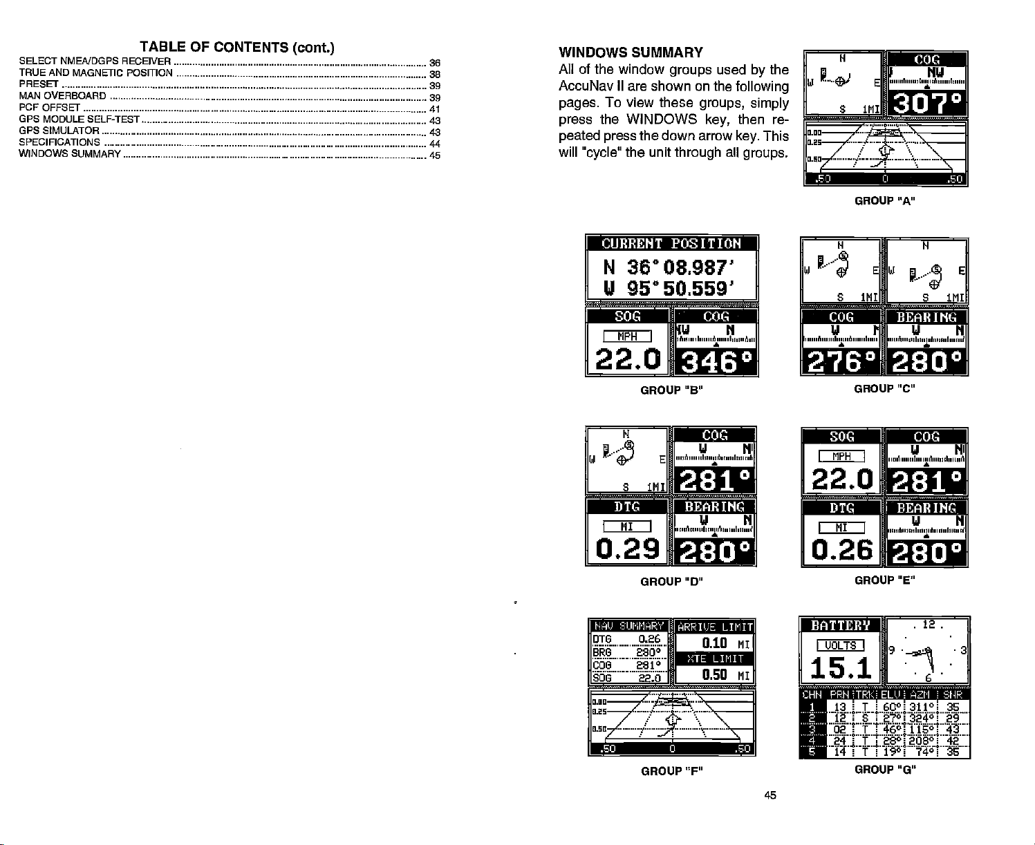
WINDOWS SUMMARY
All of
the window
ACCUNaV II are shown on the
pages.
press
peated press
will
To view these
the WINDOWS
"cycle"
the unit
groups
the down arrow
through
Used
groups, simply
key,
all
the
by
following
then re-
This
key.
groups.
GROUP "A"
rcUEHENT
N
36°08.987'
U 950 50 559'
POSITIOFf]
—
DIe IDie
MPH
I
22.0
N
J..i,
S 1MI
MI
I
U N
I
'A,,',,' I,,,,,,A,,,,,,
LE.L
GROUP "B"
A
E
I
,,,,o ',,,,,I,,,,,i ''i,,
0.29
GROUP "D"
BRG 2800
I
''I,,,,,, A,,,,,,I,,,i,,A
a
U N
a
010 MI
N'
W
S 1111
rni4Ii
('I PI
A ',,,',I,',,,,,,I,,,,'
F*L.t*'
GROUP 'c"
{{11t
FIPII
I
I
I
'.i.4u.iu
4tiJj
fl
''''A ,,,,,,l,,,i,, A,,,,,,I,,,,,, A
I
22.O
MI
I
0.26
I
,,,iM,,,ii I,'n,,
FAEL
GROUP "E"
S IMI
ni u
U N
I'u''Ain"I ,,,i,il
U NI
a
U N
a
E
:
Lull
.4
GROUP"F"
PDF compression, OCR, web-optimization with CVISION's PdfCompressor
_______
__
GROUP"G"
45
Page 5
AccuNav II GPS RECEIVER SPECIFICATIONS
GPS Module Dimensions 2.5"H x 4.1W x 7"
Channels Five Parallel
Four continuous for
All satellites in view tracked
Update
Accuracy
PositionS
Velocity
rate One second
Maximum
Standard
accuracy
Positioning
25 meters CEP
0.25 meters/sec RMS
Without SA PDOP<6.0
D
position
achievable with
Service
INTRODUCTION
The AccuNav
mance that is second to none in its
key" operation,
has ever built. The
Eagle
and
plotter
keyboard
GPS
(DGPS) ready
Read this manual and take it with
It makes a
II is a
high quality,
the AccuNav II is also one of the easiest-to-use
wide "Ultravision" screen shows the
screens with
are also
lighted
for
reference if
great
superior accuracy.
resolution
high
for
night operation.
you
wide screen GPS receiver with
class.
menu features and "soft-
Using
and detail. The
navigation
display
This unit is also differential
the first few times
you
need it.
you
use
perfor-
products
and
unit.
your
NMEA 0183 SENTENCES
RMB
RMC
OLL
APB
Minimum Recommended
Minimum Recommended
Present Position
Autopilot Steering
Sentence,
-
Latitude/Longitude
Data
Sentence,
Part B
Part C
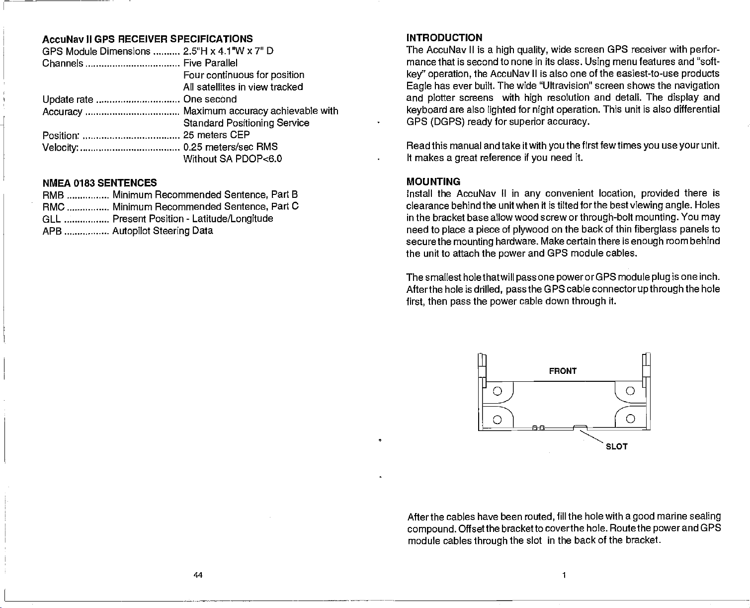
MOUNTING
Install the AccuNav II in
clearance behind the unit when it is tilted forthe
in the bracket base allow wood screw or
need to
secure the
place a piece
mounting
the unit to attach the
of
plywood
hardware. Make certain there is
power
Thesmallest holethatwill
Afterthe hole is
then
first,
pass
drilled,
the
power
pass
convenient
any
location,
through-bolt
on the back of thin
and OPS module cables.
one
pass
cable down
powerorOPS
the OPS cable
through
connectorupthrough
best
it.
SLOT
provided
viewing angle.
mounting.
fiberglass panels
enough
module
there is
You
room behind
one inch.
is
plug
the hole
Holes
may
to
After the cables have been
compound.
module cables
44 1
Offsetthe bracket to coverthe
through
routed,
the slot in the back of the bracket.
fill the hole with a
hole. Route the
good
marine
power
sealing
and GPS
PDF compression, OCR, web-optimization with CVISION's PdfCompressor
Page 6
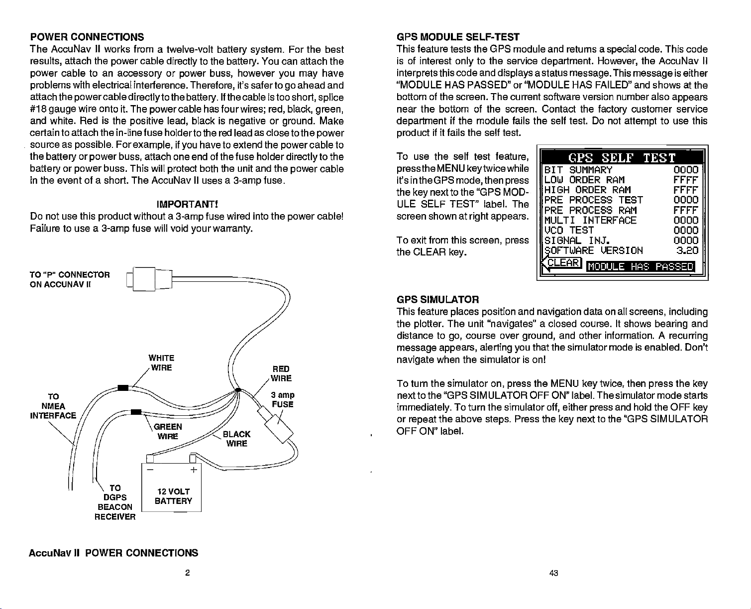
POWER CONNECTIONS OPS MODULE SELF-TEST
The AccuNav
results,
power
problems
attach the
#18
cable to an
gauge
and white. Red
certain to attach the in-line
source as
the
battery
battery
in the event of a short. The
Do
Failure to use a
TO "P'
ON ACCUNAV II
or
use this
not
CONNECTOR
II
works from a twelve-volt
attach the
with electrical interference.
cable
power
accessory
directly
or
powercable directlyto
wire onto it. The
is
the
power
positive lead,
fuse holder to the red lead as close to the
possible.
or
power
For
example,
power buss,
buss. This will
product
3-amp
without a
fuse will void
attach one end of the fuse holder
protect
AccuNav
IMPORTANT!
battery system.
to the
power
the
buss,
Therefore,
battery.
If the cable is too
cable has four
black is
if
have to extend the
you
both the unit
II
uses a
fuse wired into the
3-amp
your warranty.
battery.
negative
You can attach the
however
it's saferto
wires; red, black,
you may
or
and
the
fuse.
3-amp
For the best
ahead and
go
short,
splice
green,
cable to
power
Make
power
to the
cable
cable!
ground.
power
directly
power
have
This feature tests the UPS module and returns a
is of interest
interprets
"MODULE HAS PASSED" or "MODULE HAS FAILED" and shows at the
bottom
this code and
of
the
to the service
only
displays
screen. The
current software
near the bottom of the screen. Contact the
department
product
To use the self test
pressthe
it's in the UPS
the
key
ULE SELF TEST" label. The
screen shown at
To
exit
CLEAR
the
if the module fails the self test. Do not
if
fails
it
MENU
next to the "UPS MOD-
from this
key.
self
the
feature,
keytwicewhile
then
mode,
right appears.
screen, press
test.
press
GPS SIMULATOR
TO
NMEA
INTERFACE
WHITE
WIRE
RED
WIRE
3
amp
FUSE
This feature
the
plotter.
distance to
message appears, alerting you
navigate
To turn the simulator
next to the "UPS SIMULATOR OFF ON" label. The simulator mode starts
immediately.
or
repeat
places position
The unit
go,
"navigates"
course over
when the simulator is on!
on,
press
To turn the simulator
the above
steps.
OFF ON" label.
code. This code
the AccuNav II
This
message
customer service
attempt
to use this
department.
a status
message.
special
However,
version number also
factory
P CPS SELF TEST
BIT SUMMARY 0000
LOW ORDER RAM FFFF
HIGH ORDER RAM FYFF
PRE PROCESS TEST 0000
PRE PROCESS RAM FEFF
MULTI INTERFACE 0000
LICO TEST 0000
SIGNAL INJS 0000
0FTWARE_VERSION
CLEARI
and
navigation
a closed course. It shows
ground,
that the simulator mode is enabled. Don't
the MENU
off,
Press the
MODULE HAS PR RED
data on all
and other information. A
key
either
press
next to the "UPS SIMULATOR
key
screens,
bearing
then
twice,
and hold the OFF
press
is either
appears
320
including
and
recurring
the
key
key
DOPS
BEACON
RECEIVER
AccuNav II POWER CONNECTIONS
2
43
PDF compression, OCR, web-optimization with CVISION's PdfCompressor
Page 7
difference between the
is the
location shown on
position display
tion shown on the
Use the
to move the black box to
numberthatyou
in the
numbers.
Use the
to
right
latitude,
up
change
ordown arrow
the latitude from north to
to the "ACCEPT" label
Position
the
present
and the
chart.
and left arrow
wish to
change
then enter the
when
CorrjoJ
Factor
After
you've
OFFSET OFF ON" label. This turns the PCF correction factor that
entered
This returns the unitto the last used GPS screen. It also
effect.
into
To turn these
"PCF OFFSET OFF ON" label.
the
erases
entered the desired
on. To leave this
changes off,
PCF
any
offset, thereby turning
Position
posi-
flflr
flFsET:NIooOO.oOO
keys
MOO'
the
IUSE
*I
keys
you've
offset,
screen,
return to this screen and
press
TO CHANGE VALUE
UP="N" DH="S"
if
south,
necessary.
entered the desired latitude offset.
Repeat
example,
degrees
degrees
PCF
ence between the
sition shown
position
otherwords,
on the unit is 0.012
north and 0.068
of the
chart.
press
the
key
Remember,
it off.
Correction
NUMERIC KEYS
Press the
this
the
longitude.
we have entered .012
north lattitude
east
offset. That is the differ-
the
next to the "EXIT" label.
Presetting
longitude
onthe unitand our
shown
ourposition
position
next to the "PCF
key
puts yourchanges
press
key
procedure
In this
and .068
as the
present po-
the chart. In
by
shown
degrees
degrees
shown on the
the
key
next to
the unit also
next
to
east
you
The white and
beacon
gation
receiver
used,
To connect a device
shielded,
wire on the
the twisted
receiver. The AccuNavll sends data to another electronic
devices
tape
through
through
their ends
twisted
AccuNav It's
and the shield to the black wire on the
pair
not connect the shield to
manual for more
See the NMEA section in this manual
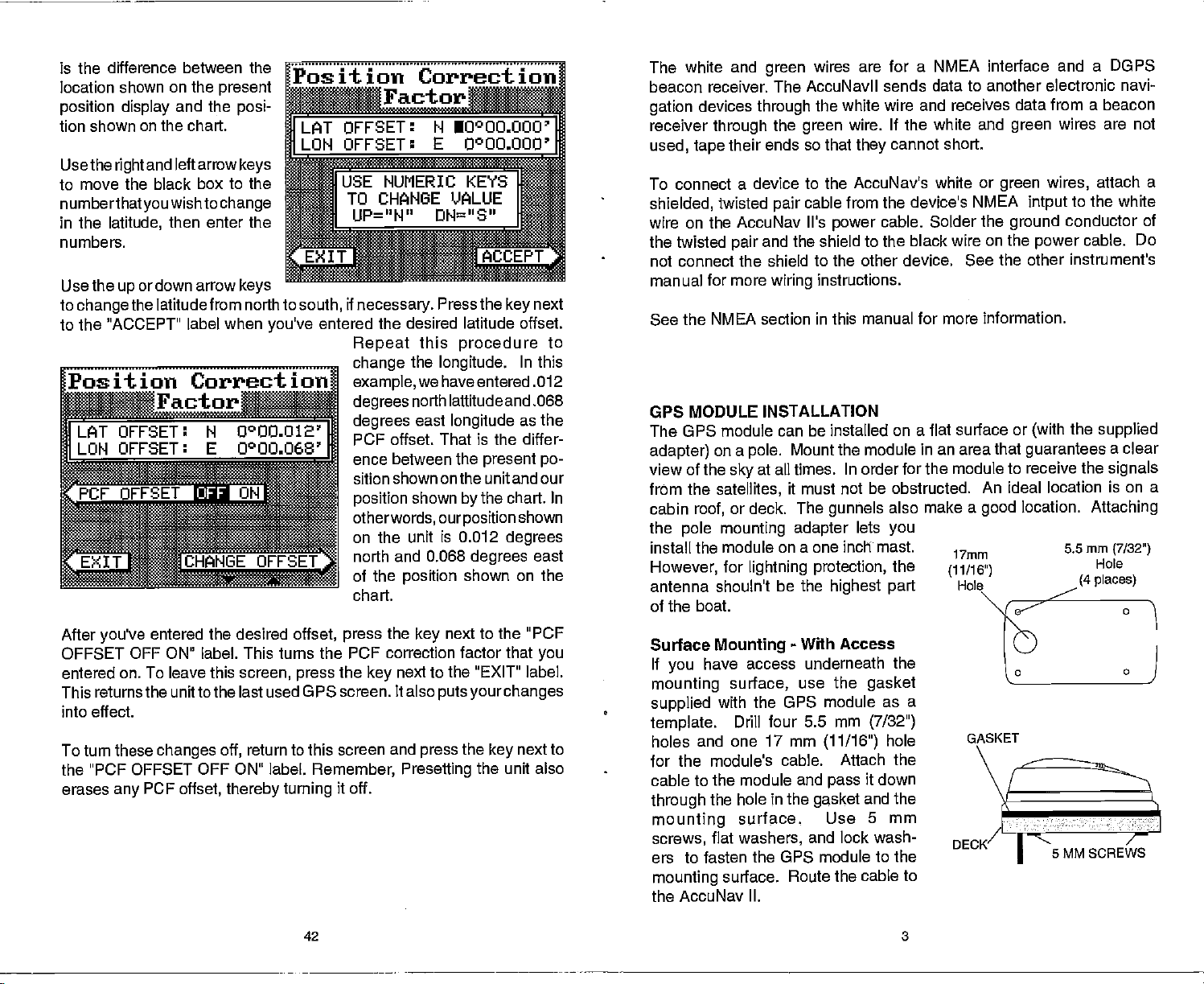
GPS MODULE INSTALLATION
The GPS module can be installed on a flat
adapter)
view of the
from the
cabin
the
install the module
However,
antenna shoutn't
of the boat.
Surface
If
mounting
supplied
template.
holes and one 17 mm
on a
pole.
at all times. In order for the
sky
satellites,
or deck. The
roof,
mounting adapter
pole
for
lightning
Mounting
have access underneath
you
surface,
with the OPS
Drill
for the module's cable. Attach
cable to the module and
through
mounting
screws,
ers to fasten the OPS module
mounting
the hole in the
surface.
flat
washers,
surface.
wires are for a NMEA interface
green
the white wire and receives
the
pair
wiring
wire. If the white and
green
so that
to the AccuNav's white or
cable
power
the other device. See the other instrument's
instructions.
cannot short.
they
from the device's NMEA
cable. Solder the
for more information.
Mount the module
it must not be obstructed.
gunhels
on a one inch mast.
protection,
be the
four 5.5 mm
highest part
-
Access
With
use the
module as a
(11/16")
pass
gasket
Use
and lock wash-
Route the cable to
also make
lets
you
the
the
gasket
(7/32")
hole
the
it down
and the
5 mm
to the
in an area that
the AccuNav II.
and a DOPS
data from a beacon
wires are not
green
wires,
green
to the white
intput
ground
surface or
module to receive the
An ideal location is on a
a
good
17mm
(11/16")
GASKET
conductor
cable. Do
power
the
(with
guarantees
location.
5.5mm
(4 places)
5 MM SCREWS
Attaching
navi-
attach
a
of
supplied
a clear
signals
(7/32")
Hole
PDF compression, OCR, web-optimization with CVISION's PdfCompressor
42 3
Page 8
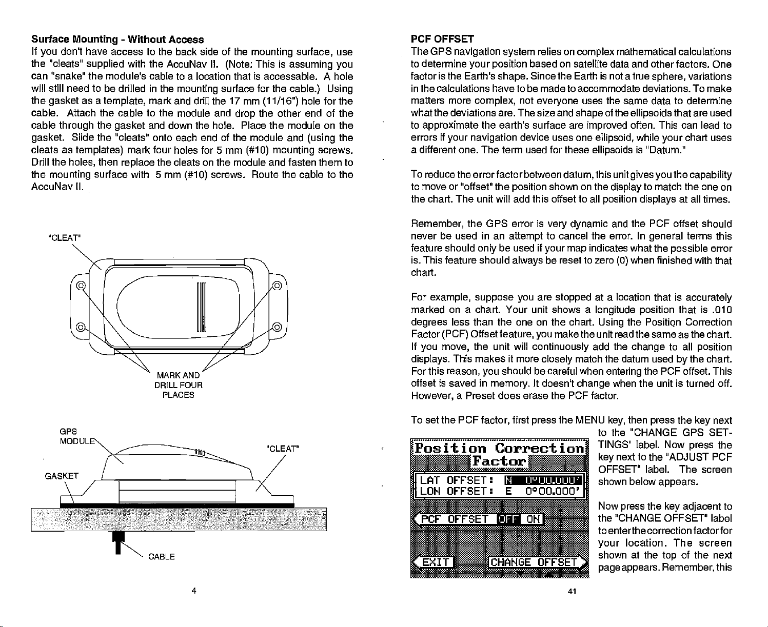
Surface
If
you
the "cleats"
Mounting
don't have access to the back side of the
supplied
can "snake" the module's
will still need to
the
gasket
cable. Attach the cable
cable
gasket.
cleats as
Drill
the
mounting
through
Slide
the
holes,
as a
templates)
-
Without Access
with the AccuNav II.
cable to a location that is accessable. A hole
be drilled in the
template,
mounting
mark and drill the 17mm
to the module and
the
gasket
the "cleats" onto each end of the module and
then
surface with 5 mm
and down the hole. Place the module on the
mark four holes for 5 mm
replace
the cleats on the module and fasten them to
(#10)
AccuNav II.
(using
screws.
use
the
mounting
This is
(Note:
surface for the
(11/16")
the other end of the
drop
(#10) mounting
screws. Route the cable to the
surface,
assuming you
cable.) Using
hole for the
PCF OFFSET
The GPS
to determine
factor is the Earth's
in the calculations have to be made to accommodate deviations. To make
matters more
navigation system
your position
shape.
complex,
what the deviations are. The size and
to
approximate
errors if
your navigation
the earth's surface are
a different one. The term used for these
To reduce the errorfactor between
to move or "offset" the
the
The unit will add this
chart.
relies on
based on satellite data and other factors. One
Since
not
everyone
device uses one
position
complex
the Earth
uses the same data to determine
shape
datum,
shown on the
offset to all
mathematical calculations
is
not a true
of the
improved
ellipsoid,
ellipsoids
this unit
display
position displays
sphere,
ellipsoids
often. This can lead to
while
your
is
"Datum."
gives you
to
match the one on
variations
that are
chart uses
the
at all times.
used
capability
'CLEAT"
GPS
GASKET
MARK AND
DRILL FOUR
PLACES
CABLE
Remember,
never be used in an
feature should
is. This feature should
chart.
For
example, suppose you
marked on a chart. Your unit shows a
degrees
Factor
If
you move,
displays.
For this
offset is saved in
However,
To set the PCF
Position Correct
the UPS error is
attempt
be used if
only
always
less than the one on the chart.
Offset
(PCF)
feature,
the unit will
This makes it more
reason,
should be careful when
you
memory.
very dynamic
to cancel the error. In
your map
be reset to zero
are
stopped
make the unit read the same as the
you
continuously
closely
It doesn't
match the datum used
change
a Preset does erase the PCF factor.
factor,
first
press
the MENU
ioid
Factor
______________
LAT OFFSET:
LON OFFSET:
______________
IIJ.tAUJ.UJ.U
E 0°OO.000'
and the PCF
indicates what the
when finished with that
(0)
at a location that is
longitude position
the
Using
add the
change
entering
when the unit is turned off.
then
key,
offset should
general
terms this
possible
accurately
error
that is .010
Positipn
Correction
to all
the
by
chart.
position
chart.
the PCF offset. This
the
press
key
to the "CHANGE GPS SET-
TINGS" label. Now
next to the "ADJUST FCF
key
OFFSET" label. The screen
shown below
Now
"CHANGE
the
press
the
press
appears.
key adjacent
OFFSET" label
to enterthe correction factorfor
location. The screen
your
shown at the
page appears. Remember,
of the next
top
next
the
to
this
4
41
PDF compression, OCR, web-optimization with CVISION's PdfCompressor
Page 9

The
plotter display automatically
Overboard mode. Your
pressed
"0" Steer to the
Man Overboard
is shown
waypoint flag
key
position
the "S" with a circle and
by
was
pressed.
The AccuNav II doesn't save the Man Overboard
table.
However,
The AccuNav II
it does save the
always
shows
Man Overboard screen whenever the Man Overboard
the unitfrom
stop
to the "DISABLE MOB" label. This resets the Man Overboard
next
navigtion.
navigating
shows a .1 mile
when the Man Overboard
the
by
to
back to the
get
IMPORTANT!
position
navigation
data to the
position
on the Man Overboard screen.
to the Man Overboard
display
waypoint
saved when the
position
in the
position
position, press
shown on the
is
key
in the Man
was
key
icon with a
waypoint
the
To
key
pressed.
Pole Mount
thread the
First,
base.
Align
the boat. Install and
and
tighten
unscrewing
adapter.
through
module on
the
pole mounting adapter
the
pole mounting adapter
the set screw into
should
This
pole.
Place the
it
securely.
from the
tighten
Now attach the cable to the GPS module
gasket, pole mounting adapter,
of the
top
pole mounting
holes in the module with the holes
onto the
so the module will face the bow of
prevent
gasket
adapter
in the
pole
the four stainless steel 5 mm screws and lock
AccuNav
completes
attach the
II,
the
assembly.
pole mounting adapter
mounting pole
the
pole mounting adapter
or ratchet
the GPS module from
onto the
and
and
align
mounting adapter. Using
washers
to the
pole mounting
and
pole.
the cable
pass
Set the GPS
the four threaded
supplied
with the
GPS module. This
For
example, suppose you
Man Overboard
the
displays
then
key again,
you
Repeated
then stores
switches backto the Position screen. If
itwill still show
first
pressed
pressing
the Man Overboard
your present position!
Overboard
must first clear
"DISABLE MOB" label.
You can
however when
stops navigating
Remember, saving
the
person
tion are
excellentsafetycourses.
procedures
do before
to
is
key
pressed.
the old
navigate
go
you
to the recalled
the victim is the
immediately
also
good
before
leaving
emergency
any
are
viewing
then
key,
press
your present position
navigation
of the Man
The unit
to a
Overboard
onlysaves
To save a new Man Overboard
Dosition by Dressing
waypoint using
back to the Man Overboard
waypoint.
after the
accident
Instructall members on board
preventatives.
dock. Make certain all on board know what
the
occurs.
the Position
the GPS
on the Man Overboard
you press
data to the
-
not
key
key
the
position
the
Waypoint
primary goal. Try
accident
happens. Training
screen,
key.
and
you press
The AccuNav II first
screen,
the Man Overboard
position you
your present position.
does not
the key
screen,
The Coast Guard has
were in when
repeatedly
save
thefirsttimethe Man
postion. you
adiacent
Recall
to the
feature,
the AccuNavll
all
options
yourboat
to rescue
and educa-
on
safety
SET
SCREW
If the
the
supplied
or mast
pole
is too small for the
pole
with
your
you're using
unit. Thread the cable
pole mounting adapter.
adapter.
Route the cable down the outside
CABLE
MOUNT-
ING
ADAPTER
POLE
POLE
MOUNTING
ADAPTER
isn't hollow or
connectors,
Then thread the
DULE
POLE
if the hole in the middle of
use the cable
mounting
pole
of the
mounting adapter
adapter
into the OPS
into the cable
pole.
CABLE
MOUNT-
ADAPTER
POLE
mounting
ING
PDF compression, OCR, web-optimization with CVISION's PdfCompressor
40
5
Page 10

KEYBOARD
The
keyboard
row at the bottom. The
numbers,
in the bottom
key
The
keys along
markers or man overboard
arrow
keys.
WINDOWS
customize
-
P05
Press this
has
keys
activate the
right
the bottom of
-
This
key gives you
displays.
to show
key
arranged
keys
windows feature and menu selections.. The menu
comerof the
in
two vertical columns
in
the left and
keyboard
columns are used to enter
right
activates thefirst menu
a horizontal
plus
the screen are used to activate the event
feature,
the Position Screen.
and make menu selections with the
access to the windows
mode,
which lets
page.
you
PRESET
The Preset feature returns all sonar and GPS units to their
settings.
contrast,
To
appears.
the AccuNav II
to their
This resets the units of
and more. This doesn't erase
the
preset
unit,
press
Pressthe
key
returns to the GPS
nexttothat label. The menu screen
factory settings.
measure, speaker volume,
the MENU
position
any waypoints
until the "PRESET UNIT' label
key
screen. All units will be returned
or
routes,
original
disappears
factory
display
however.
and
PLOT - This
-
NAV
STEER
MENU
WAYPOINT QUICK SAVES Press this
WAYPT SAVE
WAYPT RECALL
ALARM - Use this
CLEAR
EVENT MARKER
MAN
switchesthe unit into a modethatshows
ARROW KEYS - These
objects
ON - The
OFF - Press and HOLD the Off
key gives
Pressing
-
Press this
-
Press
this
-
-
This
key
OVERBOARD
on the screen.
ON
key
access to the Plotter.
this
Pressing
shows the
key
to show
key
to show the menus and
key
this
-
Press this
to set the OPS alarms.
key
clears menus and erases entries from the screen.
-
To mark a location on the
-
Pressing
keys
turns the AccuNav II on.
Navigation Display.
the
Steering
keyto instantly
lets
key
to recall a
key
this
key instantly
are used to make menu selections and to move
to turn the AccuNav II off..
key
Screen.
save a
you
waypoint.
plotter screen,
navigation
6
access to most functions
gain
save
yourpresent position.
waypoint.
use this feature.
saves
your present postion
datato the last saved
and
position.
MAN OVERBOARD
One of
boating's mostterrifying
events is
fall overboard. This situation can be
salt. It's
course,
measures to
can use
Once
the
appears.
shown in the
that
the
Course
display. Using
of the
overboard
particularly dangerous
the first
the AccuNav II to
back at the helm after
you're
AccuNav Ii's
Your
you pressed
navigation
(COG),
display gives you
position.
to do is remain calm and
thing
to rescue the
try
M4N
position
top
at the time
left corner of the
the Man
data
displays
and Time To Go
these
displays along
the information
at
night
person.
start a search
help
OVERBOARD
you pressed
display.
Overboard
showing
(TTG)
•
DISABLE 1'flbJ
0113
BRG
COG 113°
T1G99:99:991W1
a friend
having
deadly
initial rescue efforts have
on
any body
or if
you're
If
lose
you
pattern.
The screen shown below
key.
the Man Overboard
Beneath the
At the bottom of the screen are
key.
the Distance
back to the
with the
plotter
need to steer back to the man
you
jQiltlN
orfamily
of
water,
out of
sight
all standard
try
of the
sight
position
(DTG), Bearing (BRG),
postion
in
at the
the lower
36°09.002'
9S°OE49'
rrt
S:08;58 AM
Q43 IU1 id.
2390
IN
flj
39
member
fresh or
of land. Of
safety
person, you
failed,
press
key
is the time
of the
top
corner
right
N
r
S iii
E
is
PDF compression, OCR, web-optimization with CVISION's PdfCompressor
Page 11

The lower half of the screen
shows statistics for each of the
receiver's five channels. This
includes the
(PRN),
Differential
User
(UDRE),
and if SA
on or off. The UDRE is the _____
is
error
range
satellite number
its status
(STAT),
Range
Time status
(Selective Availablity)
from
your position
the
Error
(TIME),
to the satellite. If there is an "OK" in this
satellite
is 8 meters or less 68
percent
15 OK 01<
13 OK OK OK OFF
02 OK OK OK ON
ë7 OK OK OK ON
BAD OK BAD ON
26
11
_______
CLEAR
the
then
field,
of the time.
OK OFF
range
_________
error to that
-
GPS
HOW IT WORKS
The Global
Positioning System (GPS)
is the
that has ever been devised. Conceived
and the United States
(DOD)
needs of 24 hour
Basically,
Earth
system
the
system
11,000
miles in
is
fully operational.
global positioning,
works
space.
Three more
military,
by using
There will
total of 24. When all satellites are in
view
nearly anywhere
requires
in
it locks
at least three satellites to
latitude/longitude.
on to at least four
on
Earthtwenty-four
A 3D fix is
satellites,
the G PS
365
a constellation of satellites
place,
a "2D"
give
latitude/longitude plus altitude.)
your
it
displays
best
the
by
days
approach
Department
system
a
year.
to
navigation
of Defense
is an answerto their
orbiting
be 21 satellites in orbit when the
satellites will act as
at least
hours a
four of them will be in
The OPS receiver
day.
fix.
2D fix is
(A
spares,
your position
for a
When
a 3D fix.
For
more
information,
read
beacon receiver's manual.
your
SELECT UNITS OF
MEASURE
the Select
(See
TRUE and MAGNETIC
True and
the world. It's
location our
true
north,
Charts are
north. If
you plot
either have to convert
The AccuNav
When it's turned
the MENU
press
next to the "CHANGE
the "SELECT UNITS OF
to the "BEARING" label. This
Press the
Units of Measure in the Plotter section of this
POSITION
are not
magnetic
north
where all lines of
compasses point.
at a location in
usually
laid out
always
longitude converge. Magnetic
It lies several hundred miles to the
Canada.
according
a course on a chart
magnetic
II can
display navigation
on for the first time
while
key
GPS SETTINGS" label. Now
MEASURE" label. Now
next to the "EXIT' label when
key
readings
a GPS screen is
moves the black box
manual.)
the same. True
to a Mercator
the Mercator
using
to true or use true
north is the
north is the
projectionthat
projection, you'll
readings.
usestrue
of
top
south of
It takes three satellites to
information in
magnetic
displayed.
is used. To
simply
magnetic
Next, press
the
press
press
from "MAO" to "TRU."
finished.
you're
38 7
or true.
switch to
the
next to
key
the
key
true,
key
next
receiver locks on to each
As the
satellite
it. Each
when the
against
(travelling
you
the receiver
by measuring
satellite has an
radio transmission started. The receiver
own
its
atthe
speed
calculate distance. Once
can
can determine
the
length
extremely
thus it knows how
clock,
of
lightl)
position.
satellite,
of time
accurate
to reach it. If
you
determine
it calculates
position.
it takes the radio
clock that tells the receiver
it took the radio
long
knowtime and
you
have this
from three
the distance from the
to reach
signal
compares
that time
speed,
satellites,
signal
then
then
PDF compression, OCR, web-optimization with CVISION's PdfCompressor
Page 12

ACCURACY
You
The DOD
However, only
us and other
coding.
Civilian
than the
benefit from excellent
most accurate
code can
adequate
have heard
may
requires accuracy
the
military gets
unauthorized
In other
GPS receivers use "C/A Code." It's
military's
words,
system away
accurate
give
for most
"P Code." In
people.
tales of
people
the data
position
position
extraordinary accuracy
of 10 to 15 meters from the satellite
this
precision.
from
using
coming
this
fixes.
from
fixes
from the satellites is
accuracy
manner,
potential
civilian users worldwide can
Meanwhile,
enemies.
to 15 meters. This is more than
up
from GPS receivers.
The
the more
the
way
precise system
is
intentionallyworse
the
military keeps
Theoretically,
military keeps
encrypted.
system.
is
the
C/A
DGPS
You'll have to tell the
and
key,
press
previous page appears.
The beacon receiver is
frequency
Repeat
page.
shown below
(Differential
the
set
up
then
pressthe keynexttothe
the
key
and bit rate of the station
the above
Now
press
GPS)
AccuNav II which beacon receiver's data to
parameters
next to the
steps
the
key
appears.
BEACON RECEIVER SETUP
for that data. To do
"CHANGE GPS SETTINGS" label. Now
"SELECT NMEA" label. The screen on the
Press the
selected,
to
getthe
next to the
next to the
key
now
you'll
be
you'll
NMEA
screen as shown on the
"SETUP BEACON" label. The screen
first
this,
desired beacon receiver.
need to set it
in
using
your
press
area.
the MENU
up
expect
for the
previous
However
accuracy
"Selective
added to the
Of
course,
horizon,
more the
(the
not be usable if the SA is
may
off the
Don't let this
updates
to use.
systems.
market
The EAGLE EGP-1 GPS Module
This GPS receiver is
rugged,
and
acquire up
to the AccuNav II once
receiver
ing capabilities,
GPS marine
(as
of this
writing),
the
in the hands of the
Availability"
system
accuracy
signal-to-noise
better),
screen even while
discourage you,
than other
Accuracy,
You've
We
today.
and fast. The five channel
or SA. This is
so
your accuracy
also
depends
the number of satellites tracked
ratio,
and otherfactors. The smallest
high.
you're sitting
however. GPS
systems (such
even with SA on is still better than most
purchased
hope you'll enjoy
one of thefinest
currently
used in all
to five satellites at one time. It sends
second.
every
technology
navigation systems
with
Eagle's
Eagle brings
1'
to the consumer the most advanced line of
military
world.
isn't satisfied with C/A's
it's
So,
small,
will
on the
The
present position symbol
still.
as
Loran),
it for
design
By incorporating
state-of-the-art
available in the world.
8
degrading
random
typically
angle
navigatiorrinstruments
many years
Eagle
lets it track all satellites in view
be
of the satellite above the
nature has much
by
and
typically
GPS receivers. It's
design
potential
it further with
errors
intentionally
within 100 meters.
at one time
on
ranges
the
can move
is
much easier
other
navigation
plotter
faster
on the
to come.
small,
position
information
Rockwell's GPS
and manufactur-
The station
rate are shown on the
of the screen.
adjacent
increase the station
orthe "DEC
it. Do the same
When the station
bit rate are
proper settings, press
next to the "EXIT" label. The
AccuNav II returns to the last
appear
position, showing
To viewthe status of the beacon
menu
GPS STATUS" label. If the
transmitter and is connected
frequency
Press the
to the "INC FREQ" to
FREQ"to decrease
for the bit rate.
frequency
adjusted
next to the
page appears.
to the one shown at
pears.
This
number,
rate,
=
(0
strength (the higher
ber,
to-noise ratio
erthe SNR
shows the station ID
page
its
frequency
the "health" of the station
=
5
best,
the
better),
worst), signal
and the
(SNR).
number,
and bit
side
right
key
frequency
and
to
their
the
key
"POSITION" on all screens that show
that the beacon receiver is
Now
press
beacon receiver is
properly
right ap-
and bit
the num-
signal-
The
high-
the better.
used GPS screen. The letters "DGPS"
your present
working.
signal, pressthe
the
key
adjacent
to the AccuNav
MENU
to the
receiving
until the fourth
key
"DIFFERENTIAL
data from the
a
screen similar
II,
pcn
fl15
fl13
tJ02
It27
OK OK OK
OK OK OK OFF
OK OK OK ON
OK
OK OK ON
26 BAD OK BAD
ah1
37
OFF
OH
PDF compression, OCR, web-optimization with CVISION's PdfCompressor
Page 13

SELECT NMEA
TheAccuNav II sends dataoutthewhitewire onthe
to standards set
This allows the AccuNav II to send
information to "listener"
the NMEA
by
units,
(National
such as
Marine Electronics
position, depth,
charting
other marine instruments. The AccuNav II uses the
protocols:
only.
steering, speed,
the
instrument. See the installation section in the front of this manual
connection information.
NMEA 0180 and 0183. NMEA 0180 sends
It's useful
cable must be connected to the NMEA data
power
for
mainly
and more. In order to use this
autopilots.
NMEA 0183 sends
powercableaccording
Association).
and
instruments,
autopilots,
following
steering
depth, position,
feature,
the white wire on
on the other
input
NMEA data
information
navigation
and
forwiring
GETTING
STARTED
Initialization - Power On
In orderforthe
If
you simply
in 15 minutes or less. This is called "Cold
the time
orthe time at
including
local
time.)
AccuNav
turn the unit on and
display
will
Greenwich,
the
position display
To
speed up
to lock ontothe
II
probably
England.
the satellite
the unit will find the satellites
wait,
Start." If
be
wrong,
since it will be
However,
will be correct.
acquisition
the AccuNav II or "tell it where it is" the
initialization
data:
process
is
usually
done
only
satellites,
all other
(You
it mustfirst find them.
let itfindthe
you
showing
navigation displays,
can set the time to
process, you
can initialize
itself
by
satellites,
UTC time
first time it's turned on. This
once and
requires
the
following
your
The AccuNav II also has the
capability
to receive differential
data from a beacon receiver.
This
accuracy
before
er,
stalling
certain there aretransmitters in
area
the
ently,
the
StarLink MX-50R.
0183 data when the
NMEA SETUP
Once
NMEA data format to use. Consult the owner's manual of the other
equipment
follows:
First, press
SETTINGS" label. Now
the unit much better
gives
than normal. Howev-
purchasing
a beacon
wish to use. Pres-
you
and in-
receiver,
make
the AccuNav II can use
Magnavox
connect the
you
MRB-2A or
Please note that the AccuNav II doesn't send NMEA
Magnavox
wiring properly,
to see which format it needs. Then set
the MENU
key.
press
The screen shown above
ENTLY
INMEA
?NMEA 0180
rHFIEA 0183'SlIqRLINK DOPS
F'MAGNAUOD0P3
MRB-2A beacon receiver is activated.
Next,
press
the
key
appears.
OFF'MAGNAVOX
the AccuNav II must
the
next to the
next to the "CHANGE GPS
key
USING:
SETUP
B EAC0 N
be told which
the AccuNav II as
"SELECT NMEA"
label,
1. Present
2. Elevation above sea level
3.
Today's
The unit
position
date and time
usually only
it's been initialized
Afterthe
key,
powercable
then
press
GPS SETTINGS" label.
ALT,
TIME,
DATE" label. The screen shown below
This is the GPS
The
settings
shown at the
If
you're using
first
time,
these
probably wrong
tion and time.To
the numbers on this
simply press
arrow with the desired label.
For
example,
local
time, press
in
latitude/longitude
takes a few minutes or less to
the user.
by
and GPS antenna module
MENU
the
Finally,
screen.
setup
now in use are
of the
top
display.
the unit for the
settings
for
your posi-
change any
display,
the
key
to
the
change
nexttothe
nextto
key
(altitude)
key.
are
of
the
the "CHANGE TIME" label.
find the satellites once
Now
press
press
the
are
installed, press
the
key
next to the "CHANGE
key
next to the "SET
appears
the ON
LAT, LON,
next.
LATITUDE N 36°08.852'
LONGITUDE 14 9E°SO.484'
ALTITUDE
LOCAL TINE 10:17:23
LOCAL
DATE
1696
PM
1/03'1992_
ELATHAHGEAL
UANGETIMr
DATE
The data format
next to the desired data
key
AccuNav II will return to the last used GPS
currently
out the white wire on the
in use shows at
output.
power
Now
cable.
36
the
of the screen. Press the
top
the CLEAR
press
screen and send NMEA data
key.
The
Note: If
of the
all
can't
simply
values
don't use the "cold
you
settings
itself.
by
on this
enter
your present position
stari'feature,
to their correct
page
then
you
values. In other
have the unit find the correct
and
9
will
have to
words, you
change
PDF compression, OCR, web-optimization with CVISION's PdfCompressor
Page 14

CHANGE POSITION
Use a chart to determine
longitude
if
you
AccuNav II should
your present position,
The screen shown below
"N" to
simply
tude
Noticethatthe
is in
hundredths of a minute.
seconds!)
take,
row
ber in the latitude that needs
changTh
that
enter a
if
"5",
enter
the numbered
using
degrees,
If
press
to move to the num-
keys
Aft rthe latitude
enter doesn't have to be
you
position
necessary.
your present
position
minutes,
make a mis-
you
the left or
next to the "ACCEPT' label.
Now
"CHANGE LON"
longitude. Again,
or west
numbered
longitude
press
CHANGE ALTITUDE
To
enter
label. The AccuNav II needs to know
your height
cient.
arrow
in Death
You would need to
change
done.
the
press
the
Use
key
key
label. The black box will be next to the "E" on the
use the
longitude,
Be certain to enter a zero "0" as the first number in the
keys.
if it's less
key
your present altitude, press
the numbered
if
Valley
than
next to the "ACCEPT' label.
above
altitude is below sea level. For
your
and the
itto -35 feet. Pressthe
your position
within one
quickly
find
first
press
appears.
Next,
lati-
keys.
entered
and
(Not
ar-
right
your
the
as
next to the
or down arrow
up
if
necessary.
100
degrees! Afteryou've
the
ground.) Again,
to enter
keys
spot you're standing
enter the
numbers
key
Use the down
LOCAL TIME 10:17:23 PM
LOCAL DATE 1'03'1993
_____________________________
IUE ICKEYSIP
fl
LccEPT
nexttothe "ACCEPT" label when
if
don't know
you
extremely
degree
key
LONGITUDE U 96050.484?
Now enter the
of
your present position,
actual
latitudeflongitude.
next to the "CHANGE LAT"
arrow
LATITUDE N 36008.852?
ALTITUDE 1696
TO CHANGE
UP="N" DN="S"
_________________________
to switch the "E" to "W"
keys
entered the last
the
your
next to the "CHANGE ALT"
key
elevation above sea level.
an
approximation
altitude data. Press the
your
example,
it. The latitude!
accurate.
key
longitude using
Typically,
To
to
change
LJALUE
is
usually
suppose
change
number,
you're
label.
(Not
suffi-
in is 35 feet below sea level.
"35",
then
press
the
up
arrow
key
you're
the
the
the
up
to
ARRIVAL ALARM
The arrival alarm sounds a tone when
radius of a
mile
is
adjustable
XTE ALARM
The XTE
error is
changes
from 0.0 to 9.9 miles.
ANCHOR ALARM
The anchor alarm sounds a tone when the
a
preset
(600 feet),
waypoint.
a recalled
of
from .01 to 9.9 miles.
(cross
greater
the XTE
radius. For
then the alarm will sound if
the location where
CHANGING GPS SETTINGS
The AccuNav II must be initialized when it's turned on forthe firsttime. This
is described at the
ifyouwishto change only
the
parameters (such
use the menu features in the
"CHANGE SETUP" menu. To
do
this,
press
then
"CF-lANGE GPS SETTINGS" la-
bel.
Finally, press
to the "SET
TIME,
shown below
the
press
LAT, LON, ALT,
DATE' label. The screen
appears.
For
example,
waypoint
track
than the alarm's
range
you
beginning
the MENU
key
the
if the arrival alarm's
alarm sounds a tone when
error)
on the
example,
set the alarm. It's
of the GPS section in this manual.
one of
as
time),
key,
next to the
next
key
if
you
your position
the alarm sounds if
setting. Changing
steering
screen. The alarm is
present position
set the anchor alarm to .1 nautical mile
move more than 600 feet from
you
adjustable
LATITUDE N 36°08.852'
LONGITUDE
ALTITUDE 1696
LOCAL TIME 3:27:16 AM
LOCAL DATE 8'03'2032
'CHANGELATRZflW"ZLT
==
aGE LONJINEM
is within the alarm's
come within .1
you
setting
is .1 mile. The alarm
cross track
your
XTE alarm
the
moves outside
from 0.01 to 9.9 miles.
U
95°5O.484'
also
adjustable
However,
..
DATE
frE
menus on
the
Using
Initial
Position,
other initialization
described in the initialization section at the
After
you
Time-Date-Time
make a
change,
this
setting.
and
following
All of these menus work
the unit returns to the GPS or
Offset,
menu
pages, you
or Altitude without
identically
beginning
can
change
affecting any
to the ones
the
of the GPS section.
screen.
plotter
CHANGE TIME
To
change
"CHANGE TIME" label. The screen shown at the
the
appears.
the local time
(the
time at
your position), press
10 35
the
of the next
top
key
next to
page
You
miles)
position
need to re-initialize the unit if
may
with the unit off. In this
to
help
move a
you
example you
the AccuNav II find the correct satellites
would need to enter a new initial
long
distance
(over
quicker.
100
PDF compression, OCR, web-optimization with CVISION's PdfCompressor
Page 15

to enter
keys
arrow
up
time from
the
down arrow
to AM.
to the "AC-
you're
fin-
LATITUDE
LONGITUDE
ALTITUDE 1696
LOCAL
LOCAL
L41
'AM"DN'PM"
date,
press
When
you're
of the screen
If
every-
the
to the
position
searching
in view.
in a few min-
key
E>IT IaISACcEPT.
below
finished,
should becorrect.
LONGITUDE
for
TMERIC
ACEPT
II is turned
it
box",
lock on to the satellites
the
satellites,
entered the
instead of west.
start
message
to find the available
Remember,
perhaps
wrong
to the receiver,
GPS SETTINGS" label.
START" label. The unit
satellites. It
when it
11
N 36*08.852'
W 95°5O.484'
TIME 10:17:23
DATE 1/03/1993
WNUMERIC KEYS
TO CHANSE
appears.
press
LATITUDE
ALTITUDE
Enter the date
the
TIME
DATE 1/ 03/1993
VALUE
"ACCEPT" label.
key
If
theyaren't, press
36°O8.862'
N
1.l 9S°5O.484'
10:17:23
CUALUE
automatically
can send a cold start
the data
using
it is
data
Or if
you've
does,
your
sends
you've
the
using
by
press
should lock on to them in
wrong
accident.
moved
the MENU
local time and
using
1696
KEYS
a "cold start"
message
given
data. This
For
example,
a
distance
long
key.
Finally, press
will
begin
possibly
the
to
or if
it,
Now
a cold
black box moves over the num-
bers on the
example
next
selected.
Now
"CHANGE
screen shown below
The
in a window
Use the numbered
next to the "ACCEPT"
to .2
the 2
again.
has been entered,
key
The
screen as
that the alarm
cally
is
automatically
Remember,
an
arrival
Now
alarm or
the "EXIT" label
alarm menu.
You can return
screen
alarm,
on,
works
the others.
alarm
shown
the arrival alarm is
page,
the
press
current alarm value shows
mile,
press
then
key,
When
next tothe
unit returnsto the ALARMS
shown below. Notice
turned on. If an alarm
been
and
off,
alarm to less than one
you adjust
alarm to .5
can
you
press
at
anytime
turn one
as desired. Each alarm
and
adjusts indepentlyof
Adescription
follows.
side. In the
right
atthetop
key
LIMIT" label. The
on the screen which
the 0
press
the desired value
"ACCEPT' label.
has automati-
turns
if
you
change any
the
to this alarm
off,
of the
next to the
appears.
to
keys
need to set
miles,
to leave the
to
or
change
label to enter it. For
then
key,
the 0
key
the
press
the unit
it,
it on.
(1),
press
other
next to
key
adjust any
all of them
of each
ARRIVAL_ON
<TE
p
NCH0 flF4
I
IT
is labled "OLD
the alarm's
example,
1USE
I
I
CHANGE VALUE.
RIGHT ARROW TO
OFF
Itlil
H
CHANGE
LI1Ij
VALUE"
setting,
NUMERIC KEYS TO
then
to set the arrival alarm
press
USE
the
PA
rnLuro.lr
020
EPT
___________
enter a
the
following
34
zero first. For
number
example,
keys:
to set the
0 5 0.
key
I
Use the number
the time. Press the
to
key
AM to PM or the
key
Press the
CEPT" label when
ished.
CHANGE DATE
To enter
the
DATE"
numbered
The
the
you
thing
next to
unit will switch
screen and
the satellites
show a
When the AccuNav
change
to
change
key
numbers
key
need
is
It should find
utes.
COLD START
on for the first
message
the receiver.
If the unit can't
it has trouble
can
happen
it
given
with the unit
To send a cold
the
press
the
key
start
technique
15 minutes
from PM
next
key
today's
next to the "CHANGE
label. The screen shown
keys.
atthetop
next to the label that
to
change.
correct, press
the "EXIT" label. The
start
currently
the satellites and
position
to the GPS receiver. You also
finding
if
east
longitude
turned off.
next to the "CHANGE
key
to the "GPS "COLD"
next
or less.
time "out of the
you've
PDF compression, OCR, web-optimization with CVISION's PdfCompressor
Page 16

date
display
the time and date to their
internal clock will
The GPS
satellites.
POSITION/NAVIGATION DISPLAYS
The AccuNav II
indicator,
signed
of them
"Change Display"
screens that can be customized
Windows
"Customize" section.
If the data shown in
then it means that data is
For
example,
satellites and
last known
until
you
Each of the
then
pressing
description
Satellite Information
SATELLITE INFORMATION SCREEN
The satellite information
in view. The AccuNav
channel is shown at the
the
display.
numbered one
the left side of the screen. Ev-
satellite in the constellation
ery
has a number
calledthe PRN.The PRN isthe
number in
first
TR1C
row.
the AccuNav II is
satellite,
this column. If
will
probably
keep
system updates
has a
and a satellite information screen. These
to show the most
(except
the satellite
feature on the first GPS menu screen.
section for more
if the
hasn't
position,
have
found the reason the unit has lost the satellites!
following
the
of each screen
The channels
through
assigned
the channel's
stands for "track." If
then a "T" is
tracking
theAccuNavll is
be
wrong.
proper
the correct
this clock when the
position screen, navigation screen,
important
position screen)
detail.)
IMPORTANT!
numbers on
digital
invalid. Do not
position
re-aquired
notyourpresent position!
screens is available
key
menu.)
placed
display
next to the desired screen label. A detailed
follows.
screen shows technical data about each satellite
II has a five channel GPS receiver. Data on each
of
top
are
five on
to
it,
the
in
Use the method shown above to set
local
time,
data.
by using
To customize these
is
them. The
(Press
— s
.r ii
__________________________________
HOOP
GOOP 3.87
POOP 3.33
TOOP 1.98
UDOP 2.87
12
settings.
even when the
However, you
the Windows
any
rely
flashing,
position
by
the MENU
Once this is
unit is turned off.
unit is locked on to the
plotter, steering
displays
can customize all
to some extent
(There
feature. See the
screens,
screen on this unit is
on that data if it is
then the unit has lost the
that is
flashing
Do not
navigate
first
pressing
the MENU
twice to see the
key
:ia u &i
13 T 600:31101
1
12
'O'2 rT
24
14
1
s
270132401 29
1tjjofl
1
T 250?3030t 42
1 T I
19°i ?4°T
1.69 13 02 06 24
_____________
an
done,
were de-
through
with this unit
the
are other
see the
flashing,
flashing.
is
your
key,
35
35
ERASING A ROUTE
To create a
the
"More" label. Now
Route number one
waypoints
name. If
"÷RTE" or "-RTE" labels to
After
RTE" label. This erases the
used in the
you
you've
to the "EXIT" label. This
GPS ALARMS
The AccuNav II has three OPS
alarms. One is an arrival alarm
that sounds when
within a
waypoint.
track error alarm that sounds
whenyou
than the alarm's
last alarm is an anchor alarm. It
sounds when
side of a
these alarms are set
To
appears.
label
change
preset
The next is a cross
moveoff course more
preset
a GPS
adjust
To
until the black box moves to
an alarm's
c
first
route,
press
appears
wish
to erase a different
selected the desired
you
distance to a
setting.
move out-
you
radius. All of
identically.
alarm,
turn
"IN
alarm
any
setting, press
the MENU
press
the
key
on the
route are shown beneath the route number and
cycle
route from
returns
come
The
the ALARM
press
on,
2.1fl
.
press
TE.50
key. Next, press
next to the "ROUTE PLANNING"
side of the
right
route,
press
through
route,
you
IU
the available routes.
the
press
memory. Finally, press
to the GPS
AL ON 0.1 0
>TE
key
display.
ON 0.50
the
screen. The list of
the
key
next to the "ERASE
:
The
screen shown above
next to
the desired alarm's
desired alarm until the
"ON",
the
key.
the
key
as the screen below shows.
next to the
key
33
next to
key
label.
next to the
the
key
next
To
PDF compression, OCR, web-optimization with CVISION's PdfCompressor
Page 17

IMPORTANT!
Turning
the next
the unit will still show
at the time the arrival alarm was turned of f.
CANCEL NAVIGATION
To
waypoint
to the "CANCEL NAVIGATION" label. This
Canceling navigation
memory.
MODIFYING A ROUTE
Any part
have a route
changewaypoint numberatowaypoint
key,
to
Route" label.
The list of
and name.
Using
movethe black boxto
number
next to the
Use the numbered
change
5.
the "ACCEPT" label. You've
changed
5.
the "EXIT" label
ished.
Remember,
the arrival alarm off
waypoint
the AccuNav II from
stop
in a
route,
It
merely stops
of a route can be
consisting
then
the "Route
the
3. Now
the
Next,
press
Finally, press
the
press
Planning"
Route number one
waypoints
down arrow
"CHANGE" label.
waypoint
the
the
waypointfrom
the
and
any
prevents
in the route.
navigation
press
does not erase the route or
key
used in the route are shown beneath the route number
waypoint
the
press
keys
from 3 to
key
key
you're
of the route can be
pad
This,
navigating
the MENU
the AccuNav II from
changed
of
waypoints
next to the "More" label.
label.
key,
key
to
next to
3
to
next to
fin-
the AccuNavll from
in
effect,
data to the current
to
key
NOTE:
at
anytime.
number
number5.
Finally, press
appears
on the
tJSIEL.
—
PIE
RSE
!
changed
turns the route off.
waypoint
or
waypoint
twice. Now
all
stops
navigating.
For
example, suppose you
1, 2,
Simplypressthe
Next,
the
key
right
.OUTE it
NAME: JPiYS COLJE
navigating
press
navigation.
any waypoints
and 3 and
press
next to the "Recall
side of the screen.
1 BUOY 1
2 BUOY2
SANDY PT
i
at
time.
any
sequencing
However,
in the route
to a
the
you
the
key
wish to
MENU
key
1
next
from
next
to
forthe
searching
of the satellite above the horizon from
or direction of the satellite from
of a satellite is 180
ratio. This tells
number,
The satellites that are visible in the
lower
In the lower
you
(GDOP), position (PDOP),
is the combination
GDOP's
on
values.
any ground
Remember,
POSITION SCREEN
The
ized or
position display
cross track error
Your
longitude
minute. For
page,
degrees,
and 82
utes
present position
is the
(BRG) display.
pressed
magnetic, depending
mode the AccuNav II is in.
the
Course Over Ground
display.
the better.
right
the "Dilution Of Precision"
number
GDOP,
These
position
you
present position displays
the
present position
8.642 minutes latitude
degrees,
longitude.
Bearing
of the
right
satellite,
degrees,
you
corner of the screen under the "VISIBLE
left corner of the screen are the DOPS
is,
therefore
depend
based obstructions.
the smaller the number
screen
can view this screen
shows
(XTE), bearing (BRG),
coordinates. This
example,
50.853 min-
on the left side
to
This is
in
degrees
Bearing
then a"S"
then it is due south.
how
strong
time
value of
the better. The GPS receiver selects satellites based
it
automatically appears
Below the
Waypoint
HDOP,
always
on the azimuth and elevation
your present
on this
is 31
ex-
true or
on the
To
is the
(COG)
appears.
your position.
the satellite's
sky
(DOP)forthe
(TDOP),
VDOP,
tries to use satellites that have
-
at
any
position,
near the
is
shown in
jOM287OM
_____________
2:S:32
ELV is the elevation
your position.
For
signal
from
your
horizontal
and vertical
and
the better on all
after the AccuNav II is initial-
time
by pressing
course over
and local time.
top
minutes,
36°08.856'
N
AZM is the azimuth
example,
SNR is the
is.
position
TDOP. The smaller the
of the screen in latitude!
signal-to-noise
The
higherthe
are shown in the
SATS"
displays.
(1-IDOP), geometric
(VDOP).
of the
of the DOPs.
the PUS
ground (COG),
and thousandths of a
U U
(height)
if the azimuth
heading.
These show
The GDOP
good
satellite,
key.
U 95°50.496'
PMHIL
0101
SNR
DOP
and
The
mi
PDF compression, OCR, web-optimization with CVISION's PdfCompressor
32 13
Page 18

At the bottom of the screen are the Local Time and Cross Track Error
Displays.
and Cross Track Error
STEERING SCREEN
The
travelled. This is called a Course Deviation Indicator or
Distance To Go
(BRG),
screen.
Yourpresent position
the boat is
the
Please note that
displays.
steering
screen shows a
(DTG), Speed
and Course OverGround
is shown
In
theory,
relative to
heading
waypoint.
steer the boat with the arrow _____ _______
always pointing
waypoint,
the
extendingfromthe
track or
travel
to
keep
line. The
by
display.
waypoint,
the
then
waypoint.
path you've
directly
the arrow on the center
waypoint
a box at the
As
the arrow andthe boxwill move
waypoint,
The numbers on the
showing
have a black box
the
the distance
surrounded
towards the
will arrive at
you
The solid line ____________________________
arrow
taken. To
to
awaypoint, try
is
depicted
of the CDI
top
youapproach
the
waypoint's
top
remaining
distance to the recalled
surrounding
FAST the
a black
by
box,
must recall a
you
pictorial
Over Ground
(COG).
arrow. The arrowshows the direction
bythe
________________________________
if
you _______
flu'
___________________________
isyour
______________ _____________
____________________________
waypoint
view of
(SOG), Bearing
Pressthe STEER
'in
to use the
boat and course
your
CDI. It also shows
22.02
___
278°
the
___________________________
closertogether.
4
box will move to the bottom of the
left side of the screen are distance
waypoint.
then the distance markers is
them,
waypoint.
then
you
In other
have
words,
passed
298° N
If
if the numbers are
the
waypoint
Bearing
to
Waypoint
keytoviewthis
________
travel
you
past
display.
markers,
If the numbers
showing
and need
to turn around.
The numbers
gives you
is
halfway
range
CDI
alarms to
Using
an idea of how far off course
between the course line and the outside
is 0.5
is the same as the CDI alarm
range
change
the
digital displays
immediately
then
miles,
the CDI
below the CDI are the
are. For
you
cross track error is to the
your
setting.
range.
at the bottom of the screen
CDI
example,
left line and the CDI
See the
in miles. This
range
if the arrow
left 0.25 miles. The
section on GFS
with the
graphical
the
press
forthe second
all of the
next to the "CHANGE" label and enter the
key
waypoint
waypoints
in the route. Continue
have been entered for the route. Then
next to the "EXIT" label. This saves
IMPORTANT!
You must select
other
words, suppose you
and
1, 3,
this
5.
However,
case, you
waypoints
must select
in
the order
want a route that consists
wish to travel to 3
you
waypoint 3, 1,
the route.
FOLLOWING A ROUTE
To follow a
"More" label.
the
press
appears.
list of
name. If
different
key
Route number one
waypoints
you
route,
route, press
Next,
next to the "Recall Route" label. The screen shown below
used in the route are shown beneath the route numberand
wish to recall a
press
press
the
the MENU
the
nexttothe "Route
key
appears
key
next to the "÷RTE" or "-RTE"
labelsto
cyclethroughtheavail-
able routes.
After
you've
sired
route,
you'll
box
surrounding
waypoint
the
wish
first
ply press
in the route. This is
starting waypoint
to start
waypoint
the route
the
start the route
selected the de-
notice ablack
first
the
box. If
using
in the
next to the "START RTE" label.
key
using
sim-
route,
a different
—
Sb%ZZ
VERSE
you
the
waypoint, simply
to move the black box to the desired
next to the "START RTE' label.
To follow a route
For
example, suppose you
numbered
show
navigation
travel backward
2
first,
then
forward or reverse
the
route,
backwards,
press
have three
and 2. If
3,6,
data to
through
and end with
6,
through
travel forward
you
waypoint
the
route,
waypoint
the
route,
number 3
the arrival alarm sounds until
entering
route in
your
are to be used in
they
first,
and 5 in that order when
then
key,
on the
+
press
right
RTE
—RTE
the
memory.
of
waypoint
then
the
Planning"
side of the screen. The
ROUTE * I
WflME: JAYS COVE
WJPQI.1
2BUOY2
3 BUOY 3
However,
use the down arrow
waypoint
the
the unit will start with
when
number. Then
next to the "REVERSE" label.
key
waypoints
through
first,
number
you
you
in a route and
the
then
6,
3. No
matter
reach the last
off.
turn it
waypoint
waypoints
press
the route.
and
1,
finally
next to the
key
label.
if
you
press
the unit will
route,
and
finally
waypoint
if
waypoint
number
until
the
key
numbers
5. In
making
Finally,
wish to
key
the
key
they're
2. If
you
number
travel
you
In
in
14
31
PDF compression, OCR, web-optimization with CVISION's PdfCompressor
Page 19

This menu lets
the
waypoints
a Route
Name
To
assign
label to move
appears
until the black box moves to the "NAME"
to the "CHANGE" label. The screen shown below
Use the
screen to enterthe
the
name. For
route
ber "4"
letter
dow.
row
to the next
press
appears
this
name has been written
"ACCEPT" or "ENTER"
You can now enter the
Waypoint
If
you've
screen. If
keys.
below
Now
of the
to first in the route. For ex-
ample,
number 8to be
key.
waypoint,
spaceto
number.
next to the "ACCEPT" label.
The cursor should now be
thesecondwaypointline. Again,
a name to a
in the window at the
keys
example,
"REEF
repeatedly
key
"R"
appears
Next, press
to move the black box
key
letter
"1"
the
on the screen.
process
Selection
named a
not,
Now
press
appears
the numbered
press
waypoint you
if
you
If
you've
it shows in the blank
the
right
Next,
select the
you
used in the route.
through
on both sides of
1", press
key.
until the entire
move the black
first,
the list of routes. When
waypoint
to name a
the num-
until the
in the win-
the
right
position.
The letter "E"
route,
the
key
wish to
want
waypoint
press
named the
of the
waypoint
press
route
number,
route,
ar-
Now
Repeat
on the screen. Now
label. The AccuNav II returns to the route menu.
waypoints
the black box
next to the
key
go
the
the
key
on
the
press
of the
top
used in the route.
box to the "0"
"CHANGE" label. The screen shown
NUMERIC
KEYS TO
CHANGE
8
UALUE
U
EXIT
30
name the
next to the "-i-RTE" or "-RTE"
key
the desired route number
screen, press
position.
press
should be on the "0" at the
using
USE
and choose
route,
the down arrow
Now
appears.
the
the
RTE#
NAME REEF1
..P
the
press
next to the
key
top
or down arrow
up
key
6
0
0
=iACCEP)
key
next
of the
display
rately
waypoint.
NAVIGATION SCREEN
Use the
when
waypoint.
tance To Go
Waypoint
Speed
Course Over Ground
and Cross Track Error
waypoint,
appears.
CUSTOMIZE SCREENS
The
plus
To show how this is
To customizethe Position
menu screen
DISPLAY'
turns to the Position
with a black
Bearing (BRO)
The black box
Bearing
change."
ing display, press
down arrow
display
inside the box.
In this
by pressing
at the
steer
navigation
you're navigating
(BRG),
Over Ground
then
digital displays
all the
box as
To
that
example,
h850
let
top
the boat to a
It shows
(DTG),
press
displays
appears.
label. Thd unit re-
box around the
label.
identifies the
change
keys
want
you
we
the
up
NORMAL
accu-
you
screen
to a
Dis-
your
Bearing
Local
Time,
(SOG),
(COG),
(XTE).
NAV
the
on the bottom
on the
Navigation
we'll
done,
Screen,
Press the
Screen
"ready
the Bear-
the
up
to select the
to show
changed
arrow
key
DISPLAY
...'.
278 MI
c
Mifli
to
rwqi
2:68:19
To
use the
A screen similar to the one above
key.
half of the Position and
screen can be
use the Position screen as an
first
press
next to the "CHANGE POSITION
key
N 36°08.925'
U 95°50.386'
for
rr
850
or
____________________________
2:69:15
the
Bearing display
twice.
DISPLAY READY
15
PHIHIL 021 MI
navigation
changed
the MENU
4
PM1L
to DIG
-, •I
22.0MPH
a9*H o5
4ivr
screen,
first recall a
Steering
key.
screens,
as desired.
example.
Thefirst GPS
197*
0.08 MI
(Distance
FOR CHANGE
To
H
Go)
PDF compression, OCR, web-optimization with CVISION's PdfCompressor
Page 20

To
change
play, press
row
key.
digital display
you pressthe
press
to
change
The
for use are:
BRG
Bearing
SOG
DTG
DEST WPT
POSITION
ALT
RTE NAME
WPTNAME
another
the left or
The label in the next
box
arrow
the
or down arrow
up
the
display.
digital displays
110
XTE
LOCAL TIME
COG
When
This "locks" the
as
you designed it,
PLOTFER
The
If
you've
present position,
waypoint
The
latitude and
location of other
To use the
at the
The
path you
have the
you
display. Every
lets
plotter
you
recalled a
to use the
also can show
plotter
longitude
plotter, simply press
of the next
top
flashing
cross is
have
just
dis-
digital
ar-
right
changes
key. Again,
display arranged
unless
see
waypoint,
and destination.
plotter.
objects.
your present position.
traveled. The
as
key
available
Altitude
Waypoint
Time To Go
Time at
Course Over Ground
time
you preset
yourcourse
the
lines on the
grid
lines that can
the PLOT
page appears.
large square
=l——— •i a
N 36° 08856'
U 95°
50.496'
.
27.8
Speed
Distance To Go
Destination
Present Position
Route Name
Cross Track Error
Over Ground
as
desired,
switch to this
you
the unit
and direction of travel on the screen.
plotter
However,
help you
16
MIIH
PMHIL
Waypoint
Name
location
your
shows
do not have to recall a
you
display.
visulize
A screen
key.
The solid line is
is a
287° M
0.01 MI
the CLEAR
press
display,
your starting
These
your position
compass
itwill
grid
similar to the one
your track,
rose marked
appear
location,
lines
key.
show
or the
or
Now
press
the
next to the
key
"÷ WPT" or "-WPT" label until
the desired
appears
does, simply pressthe
waypoint
on the screen. When it
to the "GO TO
label. TheAccuNav II returnsto
the last used
orplotterscreen, showing
gation
recalled.
ROUTES
A route
to
re-program
more
waypoints.
navigation
thefirstwaypoint, (signalled bythe
cally sequences
this
waypoint
in a
route,
There are four
create and name the route.
Then determine the
Finally,
After these
navigation
CREATING A ROUTE
To create a
MENU
next to the "More" label.
key
Now
press
"ROUTE PLANNING" label.
Finally, press
sonar,
data to the
gives you
the unit after
information
and the
the arrival alarm sounds until
steps required
the unitwill
steps
data to the first
route,
.
Next,
key
the
key
the
number
next
key
WYAPOINT"
navigation,
navi-
waypoint you
the
abilityto
When
navigateto
arriving
travell on a
you
to the first
to the next
starting waypoint. Next,
askyou
are
first
press
next to the
key
waypoint. Navigation
process repeats.
to create and follow a route.
Next,
if
wishto run the routeforward orbackward.
you
completed,
waypoint
pressthe
the
next to
the "SAVE/EDIT ROUTE" la-
bel. The screen shown at
appears.
rightS
*WPT
1NAME
8IL0H
jOT8
LJERO BROS
H 36009.869'
hi 95037fl'
I....
MAUI BAT I OH I h1FO
(MILES) 12S
BRO (MAO) 86°
TUflT
I8EWPT#
several
at each one. A route consists of two or
route,
waypoint
Arrival
Alarm),
When
you
select the
the AccuNav II will start
on the route.
—RTE
waypointswithout having
the AccuNav II first shows
in the route. When
theAccuNav II automati-
information is shown to
reach the last
you
turn it off.
waypoints
tell the
used in the
unit to
First,
follow
you
waypoint
you
the route.
showing
IQUTE# 1
NAME:
..
uc::::E:E
reach
must
route.
TE
TE
HG
29
::::::g:::EEEFE-:SE:
::::::g:::E:E:E:EEEEE::
.....9...................
PDF compression, OCR, web-optimization with CVISION's PdfCompressor
Page 21

name. For
waypoint
number "0"
example,
"COVE
key repeatedly
the letter "C"
window.
arrow
box to the
Now
edly
the screen.
cess
been
press
returns
with this
key
Erase a
The
To erase a
Next, press
to move the black
key
next letter
the
press
until the "0"
Repeat
until the entire name has
written on the screen. Now
the
key
to the
name,
next to the
Waypoint
Waypoint
waypoint,
the WAYPT
the
press
WPT" or "-WPT" label until
desired
pears
press
"ERASE" label.
shown at
sage appears
that
key
waypoint
on the screen.
the
key
right appears.
"WAIT!!
says
WAYPOINT ARE
SURE?." If
is the
arrow. If
you
waypoint
not,
the "YES" arrow
appears
To exit from
RECALL A
at the
the
WAYPOINT
You must recall
AccuNav II. To
screen shown
to name a
1",
press
appears
in the
the
position.
"3"
key repeat-
appears
this
next to the "ACCEPT" or "ENTER" label. The AccuNav
waypoint
first
"EXIT" label to exit the
Erase feature
SAVE
save menu as shown above. To
the
press
first
press
key.
next to the "-i-
number
Simply
to the
next
The screen _____
A mes-
on the screen _______
DELETE
YOU
are certain this
that
press
erases all information from the
top
waypoint
a
recall a
at the
wish to
you
the
key
of the screen.
waypoint
waypoint,
of the next
top
the
until
right
on
pro-
next to the "SAVE" label.
key
waypoint
lets
Now
delete
you
_____
waypoints
]NAME
the
t7f1LAT
IL0N
ap
save
_____________________________
Sr,tJc
_______________________________
i.su'.....__.naflj
DELETE bJi2iYPOINT
ARE YOU SURE?
LITh
erase,
next to the "NO" arrow.
menu,
press
in order to
first
press
page appears.
the
press
the
navigate
the WAYPT RECALL . The
save the
Now
menu.
save
from
I)ERO
N 36°09.869'
hi 95°37.171'
next
key
Press the
waypoint
CLEAR
to
that
key.
position
II
waypoint
the
press
the list.
BRDG
I'
to the "YES"
next to
key
number that
with the
with
North, South,
West. The
width shows
square's height
at the bottom of
the screen. This is the
from one side
from the
present position
of the screen.
top
If
your present position
move outside the
AccuNavll clears the
then re-draws
position
be
displayed
To clear the
to the other and
to the bottom.
top
is shown
square,
your present
closertothe centerof
on the
plotter
On the left side of the screen
(BRG), Speed
digital displays.
except
COG that is
Over Ground
All of these
a!ways
East,
distance
Your
atthe
starts to
display,
plotter.
screen,
and
and
the
N 36°O
I
22.0
104°
______
.,
the screen. Your
see the
displays
active.
Plotter Menus section.
are the Distance To Go
(SOG),
and Course Over Ground
are used when
These
See the Plotter Menus section for more
PLOTTER CURSOR
The
plotter
waypoint
the
plotter
new lines
the
present
latitude/longitude position
the arrow
Use
Toerasethecursorlines,
CLEAR
the
switch the
the
top
showing your present position.
PLOTTING WITH A
WAYPOINT
Usingthe plotterwitha
waypoint
to see the effects
way
cursor can
help you
or event marker. To use
is
displayed.
appear
position display
A screen similar to the
on the screen. These
of the
to move the
keys
press
This also will
key.
position display
of the screen back to
recalled
or route is an
easy
of wind
determine
it,
press
at the
of the screen switches to show the
top
plotter
cursor lines to the desired location.
plotter
______________________________
at
•aI
22.0
28° S
8.853' U 955O.662'
N •*Ifl
UI
_____________________
I
present position
displays
detail.
also can be customized.
the
the
or down arrow
up
one below
are the
cursor
plotter
-
not
S 1111
will
(DTG),
awaypoint
latitude/longitude
cursor lines.
your present position.
is
appears.
N
.
.
always
Bearing
(COG)
recalled,
of a
while
key
Two
Also,
1MI
28
17
PDF compression, OCR, web-optimization with CVISION's PdfCompressor
Page 22

andcurrenton
simplifies navigation.
the
plotter
recall
(See
tion for more
press
similar to the one at
pears.
in this
awaypointorstarta
the
Waypoint
the PLOT
boat. It also
your
To use
manner,
Recall sec-
information.)
A screen
key.
right ap-
first
route.
Then
N
36°09.037' U 95%0408'
L
DTEi
fl:
r
fl:
'bpij —l.
r'706 -:1
The "5" is
tion. This was
when
The
flashing
number inside is the destination
the
flag
10 is the
from the
waypoint.
An
arrival alarm can be set to sound a tone when
distance to the destination.
about the arrival alarm.
PLOTTER MENUS
Pressing
menus
PLOTTER
CLEAR PLOT
To
clear or erase the solid track
menu selection. The
continue to draw
ter this
from
SET RANGE
Use this menu to
plotter's range
across the
range
your starting
your position
recalled the
you
circle with a cross is
is the recalled
destination. The dotted line is the
starting point
the MENU
that relate
key
your present position.
onlyto
MENU - PAGE 1
your
is
pressed, starting
or distance
plotter's display.
is 1 statute milewhen the
loca-
waypoint.
waypoint
to the destination. Follow this line to
See the section on alarms for more information
while the
key
the
plotter.
plotterwill
track af-
____
your present position.
(recalled waypoint).
number. In this
plotter
There are two
line from the
PLOT
ICON=jIiJ
change
the
LARNS GOTO
The
UANGEOISP
N
f
S 2M1
The
The number inside
example, waypoint
shortest,
displays gives you
screen,
most direct course
come within a
you
of
pages
plotter
use the Clear Plot
—
1
J
jul
a.
E
with a
"flag"
number
to the
get
preset
a new set of
menus.
N.Y
S 2MI
CURSOR.
Enter New
To save a location
SAVE
to the
FIELD" label
below
keys
if
your
enter the location
save
Use the left arrow
backspace
take. In other
the left arrow
black box over the last number
entered. Notice
tion
entered
utes,
minute.
to the "ACCEPT' label. The
the
key
switch the
longitude.
degrees.
Press the
waypoint
position
next to the "SAVE" label.
Name a
To
assign
waypoint
label to move
waypoints.
waypoint appears
dow,
until the black box moves to the
"NAME'
the
key
FIELD" label. The screen shown
at
right appears.
Use the
thescreen to enterthe
Waypoint
otherthan
key.
latitude/longitude position.
appears.
to
change
latitude is south.
using
and hundredths of a
(Not seconds!) Afteryou've
next to the "CHANGE FIELD" label. Press the down
Make certain to add a zero
For
key
menu
box atthe
Waypoint
the
Using
at the bottom
up
Use the arrow
the "N" to a
you
the numbered
key
if
make a mis-
you
words,
moves the
key
that the
is
in
degrees,
longitude
example,
next to the "ACCEPT" label when
appears
of the screen. If this
top
a name to a
save menu
through
When the desired
appears.
the list of
your present position,
and down arrow
right
"Sn,
Now
wish to
keys.
as a
pressing
posi-
min-
waypoint
from west to
if the
with the
waypoint, press
in the win-
the down arrow
press
position.
next
keys
Now
to
the
on both sides of
key
press
"CHANGE
waypoint
first
move the black box down
keys,
Now
corner of the screen. The screen shown
press
the
next to the "CHANGE
key
press
the WAYPT
SuIiRF
NAME
LET N I—°--—.———'
1LON
NUMERIC KEYS
_____
TO CHANGE
UP=" N" ON=" 8"
VALUE
LJSE
entered
longitude
position you
Press the
the
latitude, press
save menu
east,
to the
is 85
position
the WAYPT SAVE
key
reappears.
if
necessary.
longitude
degrees,
you've
entered in the
is
next to the "+WPT" or"-WPT"
the
key
Next,
arrow
Now
enter the
if it's less than 100
then
enter "085".
finished.
correct, press
The save
waypoint
the
key.
next
press
to
key
key
The
15
27
PDF compression, OCR, web-optimization with CVISION's PdfCompressor
Page 23

Saving
(Quick
The AccuNav II lets
one
Present Position as a
Save
Feature)
you
key press.
This "Quick
save
Save" feature lets
of a wreck or other locations.
To save
QUICKSAVE
the first available
your present position
The AccuNav II takes
key.
waypoint
number to it.
Waypoint
present position
your
as
waypoint,
as a
waypoint
save the
easily
you
simply press
your present position
with
only
position
the WAYPT
and
assigns
AccuNav
his turned on for the
first time. The available
ranges
20, 50,
you
tions in
out" to see
tion,
course,
are.1, .2, .5,1,2,5,10,
and 100 miles. This lets
"zoom in"to see smallvaria-
course or "zoom
your
your starting posi-
present position,
and destination.
plotter
track,
Saving
The "Quick Save" feature doesn't let
Present Position - View and
you
have to use the next available number
and Save method lets
position
number that
save
to the one below
The first
the list
page.
is stored in.
already
has a
your present position, press
appears.
waypoint
appears
number in
at the
top
This is the number that
your present position
stored under. Your
the time
you pressed
WAYPT SAVE
position
is shown in
key
you pick
(Note:
of the
will be
the
You can store a
position assigned
waypoint
the WAYPT
at
the
the "CURRENT POSITION"
box in the middle of the screen.
If
wish to save the location
you
in the CURRENT POSITION
box under this
ber, simply press
The
position
waypoint
naming it, simply press
waypoint
the
shown in the CURRENT
location at the
To save the location
to the "+ WPT" label to increase
number ito
waypoint
location
label. Then
location under
used
under, press
position,
Press the
2).
number.
press
the
plot,
num-
to the "USE CURRENT POSITION" label.
next
key
of the screen. To save the
top
the
key
undera different
next to the
key
Once
you've
the
the
key
waypoint
or
navigation
decided the
next to the "USE CURRENT POSITION"
key
next to the "SAVE" label.
number
next to the "SAVE" label.
the
waypoint
screen.
Save Method
select the
when
POSITION box also will show in the
waypoint
"-
waypoint
that method. The View
using
number
position
to it
using
SAVE
key.
CURRENT PIJ TION
number,
number
WPT" label to
waypoint
number. You
that
your present
under a
this
waypoint
method.)
A screen similar
waypoint
press
(i.e.
number to save
without
the
from
decrease the
next
key
waypoint
To
the
This will store the
selected and
you
return to the last
ICON ONIOFF
Pressing
icons that
this
you placed
more information on this
turns on all of the
turns on the
key
on the screen
waypoint icons,
feature,
the EVENT MARKER
using
see the Event Marker section. This also
also.
ALARMS
Press this
for the alarms menu. For more information on the
key
see the ALARMS section.
GOTO CURSOR
As
previously
highhighta position.
hairs on the
described,
display
next to the "GOTO CURSOR" label on the
AccuNav II to show
the cross hairs. This
To use this
the
plotter
feature,
screen.
the cursor lines can be used to
When
are shown at the
you
use the
cursorlines,
of the screen.
top
the
position
plotter
navigation
automatically
and
steering
turns the arrival alarm
data to the
first move the cursor lines to the desired location on
press
the MENU
key. Finally, press
Next,
to the "GOTO CURSOR" label. The unit returns to the
waypoint flag appears
on the screen
of the cursor cross hairs when
you pressed
"GOTO CURSOR" label.
All of the
the
keynexttothe
navigation displays
on
the AccuNav II will show navi-
data to the location
gation
marked. This includes the navi-
gation, steering,
plays.
and
plotter
you
dis-
(numbered "0")
Jj••
8013
r
_____
fl:
BRI3
H 77
COG
F
II 2700 S 2111
that was the location
For
key.
alarms,
an icon or
place
of the cross
Pressing
menu causes the
position
on,
plotter
N
the
shown
also.
the
key
screen. A
key
by
next
E
26
19
PDF compression, OCR, web-optimization with CVISION's PdfCompressor
Page 24
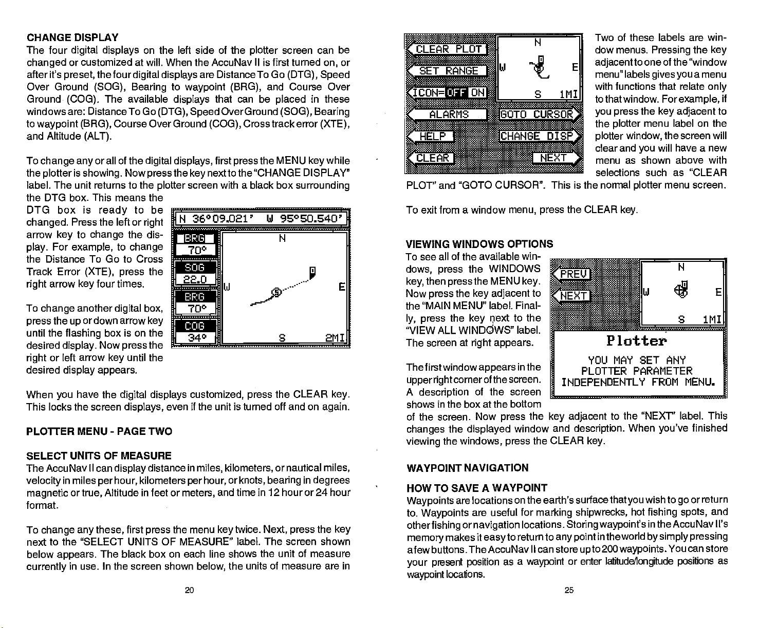
CHANGE DISPLAY Two of these labels are win-
The four
changed
after it's
Over Ground
Ground
windows are: Distance To Go
to
waypoint (BAG),
and Altitude
To
the
label. The unit returns to the
the DTG box. This means the
DTG box is
changed.
arrow
play.
the Distance
Track Error
right
To
press
until
desired
right
desired
When
This locks the screen
PLOUER MENU
SELECT UNITS OF MEASURE
The AccuNav II can
velocity
magnetic
format.
To
next to the "SELECT UNITS OF MEASURE" label.
below
currently
digital displays
or customized at will. When the AccuNav Ilis first turned
preset,
change any
plotter
the four
(SOG), Bearing
(ALT).
or all of the
is
showing.
The available
(COG).
ready
Press the left or
to
key
For
arrow
change
the
the
or left arrow
you
change
example,
To Go to Cross
(XTE), press
four times.
key
another
or down arrow
up
flashing
display.
display appears.
box is on the
Now
key
have the
-
in miles
change any
appears.
per
or
in
Altitude in feet or
true,
these,
The black box on each line shows the unit of measure
use. In the screen shown
on the left side of the
digital displays
(DTG), Speed
Course Over Ground
digital displays,
Now
press
plotter
to be
right
the dis-
to
change
the
are Distance To Go
to
waypoint (BAG),
displays
the
key
screen with a black box
N 36009.021'
r
700
that can be
(COG),
first
nextto the 'CHANGE DISPLAY"
plotter
Over Ground
Cross track error
press
_______________________
m
22.0
digital box,
key
the
press
until the
digital displays customized, press
displays,
PAGE TWO
display
hour,
distance in
kilometers
first
press
340 S 2M1
even if the unit is turned off and on
miles, kilometers,
or
hour,
per
meters,
the menu
below,
20 25
knots,
and time
twice.
key
the units of measure are in
screen can be
or
on,
(DTG), Speed
and Course Over
placed
the MENU
14 9S0S0.S40
the CLEAR
or nautical
bearing
in these
(SOG), Bearing
(XTE),
while
key
surrounding
U
r
'
in
E
key.
again.
miles,
degrees
in 12 hour or 24 hour
Next, press
The screen shown
the
key
PLOT' and "GOTO CURSOR". This is
To exit from a window
VIEWING WINDOWS OPTIONS
To see all of the available win-
dows, press
then
key,
Now
press
the "MAIN MENU" label. Final-
ly, press
"VIEW ALL WINDOWS" label.
The screen at
The first window
upperright
A
description
shows in the box at the bottom
of the screen. Now
changes
viewing
WAYPOINT NAVIGATION
HOW TO
Waypoints
to.
Waypoints
otherfishing
memory
afew buttons. TheAccuNav II can store
present position
your
waypoint
the WINDOWS
the MENU
press
the
key adjacent
the
key
right appears.
cornerof the
of the screen
the
displayed
the
windows, press
SAVE A WAYPOINT
are locations on the earth's surfacethat
are useful for
or
navigation
makes it
locations.
menu, press
flext
appears
screen.
press
easyto
as a
key.
to
to the
in the
the
window and
the CLEAR
locations.
return to
waypoint
the CLEAR
INDEPENDENTLY
______________________________
key adjacent
marking shipwrecks,
Storing wsypoint's
any point
or enter
dow menus.
adjacent
menu" labels
with functions that relate
to that window. For
you press
the
plotter
plotter
clear and
menu as shown above with
selections such as "CLEAR
the normal
Pressing
to one of the "window
givesyou
example,
the
key adjacent
menu label on the
you
plotter
the
will have a
menu screen.
window,
key.
Plotter
YOU MAY SET ANY
PLOTTER PARAMETER
FROM MENU.
to the "NEXT" label. This
description.
key.
in the world
upto
When
you've
wish to
you
hot
200
waypoints.
latitudeAongitude positions
go
fishing spots,
in the AccuNav Ii's
by simply pressing
You can store
the
key
a menu
only
to
screen will
new
finished
return
or
and
as
if
PDF compression, OCR, web-optimization with CVISION's PdfCompressor
Page 25

WINDOWS
can
You
feature. This lets
boating
change
situations. The screens
into two or more windows
"group".
shown
This AccuNavil
at
right
Course Over
steering displays showing
three
separate
can have as
group
the
displays
you
has the
Ground,
windows.
many
use different
per
givesyou
plotter,
and
in
A
as
four windows. A window can
display digital
steering
and
many
GPS
ornavigation displays,
more.
To use the windows
first
pressthe
WINDOWS
data,
feature,
GPS
key.
on the AccuNav
displays
available in the
screen. Each screen of
8 differentwindow
II
by
to suit
windows mode are divided
groups.
..-..-.
0.1111
:zJ:!::::::::x:::..'
the windows
using
own
your
fishing
windows is called a
"A" as
Group
' ' ' ' ' '
' ' ' I , ;, t
or
statute
per
magnetic
feet,
format
Press
you
press
label twice to
kilometers. This moves
box two times from
"KM'.
milesfordistance,
hour for
and time is in the 12 hour
the
wish to
the
velocity, degrees
for
bearing,
(a.m./p.m.)
next to the unit that
key
change.
to the Distance
next
key
switch from miles to
the "Ml" to the
altitude
For
example,
the black
miles
in
When
suresetasdesired, pressthekey
next to
have the units of mea-
you
the "EXIT' label.
BACK LIGHT ON/OFF
For
example, pressing
arrow
down
the
group
the windows
key
"B" screen . To exit
mode, press
once shows
the
the
P03, PLOT, NAV,orSTEER
one of the
Every
keys.
screens
can be modified to
some extent.
the MENU
press
group
new labels
play
is
"A"
appear
as shown
For
displayed.
at
group
example,
while
key
Four
on the dis-
right.
24
A screen
shown at
menu
screen lets
the
"pages"
are leftered
Group
similar to the one
left
at the bottom of the
you
of
displays.
"A"
"A" shows
the down arrow
forward
Pressthe
backward.
through
uparrowkeyto
appears.
switch between
through
The
These
"H".
first. Press
to move
key
the screens.
move
GRID LINES
The
plotter
can show
latitude/longitude grid
to the "GRID OFF/ON" label
lines
grid
PLOTTER UPDATE
The
drawing
off,
plotter
a solid line
shows
present position.
updated
once
when the unit is turned
thefirsttime.
the
repeat
yourtrack
behind
The track is
every
However,
previous
your
instantly
on for
if
you're
on the second
step.
36°08.967' hi 96°EU.656'
IN
r-b13
by
a:
r
COG
21
To turn the back
pressthe
press
menu
the
"BACK LIGHT"
lighting
keytwice,then
next to
key
label. This
moves the black box from
"OFF" to the "ON"
turn the
the
lines
plotter
backlights
steps.
pressing
by
menu
position.
off,
the
page.
1—
—I
Th.
on,
the
To
repeat
next
key
Totumthe
'a
Ui
In
C
iiii
PDF compression, OCR, web-optimization with CVISION's PdfCompressor
Page 26

travelling
track line
due to the
dots availablethat
Using a longer update
change
the MENU
in
the
the
DATE label. The
above
plot update
5, 10,
press
returns to the
EVENT MARKER
The AccuNav Il
fishing spots,
different icons to choose from and there are 100 of
500. You can
of the icons in
To
place
below
Now select one of the five icons shown on the left side of
pressing
desired
press
places
position.
in
this location. It's saved in
memory
on
the
turned off and on
Using
the
Normally,
position. However,
a
may
the
plotter
next to the PLOT UP-
key
appears.
and
the
key
an
appears.
the
icon. As soon as
the
key,
the icon at
This icon
so it will
display,
the
Cursor
when
distance,
long
end
prematurely
limited number of
plot
update rate,
while the unit is
key
mode. Now
screen shown
The available
times are
20 seconds.
nextto the desired
plotter
can
shallow
each icon
place
a
group.
first
icon,
next to the
key
the AccuNav II
your present
always stays
always
even if the unit is
again.
Event Marker with
select an
you
you
place
the
..
the track.
time To
press
press
NoS3r00.1
10
r"cONDS
rCLEAR
instant, 2,
Simply
update
screen
event markers
water,
the EVENT MARKER
press
you
show
can
the new time.
using
or other
individually, however, you
f'O8.888'
141°
it's
icon,
an icon
place
SECONOS
1U1I
time. The
or "icons" on the
special
SELECT MN ICON TO
H
•
placed
22
IDELETE ICON
on the
anywhere
UPDATE RATE
MAIT
AccuNav II
locations. There are five
each icon for a total of
have to erase all
The
key.
Ui 95°EO.709'
PLACE ON
plotteratyour present
on the
- . -.
th
CURRENT
INSTANT
immediately
to mark
plotter
screen shown
the screen
PLOTTER.
BANK
itlI
plotter
using
by
thecursor. To
one of the arrow
makes the
appear
move the lines to the
position
pressingthe
it's at the desired
press
then select an icon.
key,
AccuNav II
the intersection of the
cursor lines.
To erase the cursor
Erasing
Although you
them one at a time. You
example,
all 20.
To erase an
EVENT MARKER
the
press
LETE ICON BANK' label. The
screen shown below
Now select the
thatyou
the
ing
icon. After
AccuNav II erases all of the
selected icons from the
HELP
An
extremely
menus.
one or
gives
example,
also
appears
a
you
description
dothis,firstpress
This
keys.
cursor lines
plotter
on the
the EVENT MARKER
display.
on the
arrow
places
keys.
Now
desired
display
by
When
location,
The
the icon at
plotter
lines,
press
the Icons
can
if
you've place
first
icon,
next to the "DE-
key
group
wish to erase
next to the desired
key
pressing
useful feature
Virtually every
more
pressing
on the screen.
of each of
icons
place
have to erase the whole
20 fish
the
press
key. Next,
appears.
of icons
by press-
the
pages
the MENU
the
key,
plotter.
feature has a
of text
the menu items and how
incorporated
Pressing
N 36°09.061' hi
l'1pI:l N
60.7
22.0
700 S
the CLEAR
on the
symbol
hi E
key.
plotter
individually, you
icons,
erasing
E°°9002'
'
?
1
SELECT AN
GROUP TO ERASE
FROM PLOTTER.
J
156°
into the AccuNav II is the
menu label
help
describing
shows the first menu
key
the
23
how to use that feature. For
key adjacentto
96°SO.496'
can't erase
of icons. For
group
one of them erases
hi
96°SO 389'
ICON
hiARNING!
S 1MI
when
that,
A
page.
the
helplabelgives
work.
they
1MI
Help
pressed,
label
help
PDF compression, OCR, web-optimization with CVISION's PdfCompressor
 Loading...