

Page 1

www.eaglesonar.com
r
Pub. 988-0143-96A
Fish-finding Sona
Installation and Operation Instructions
Page 2

A
Copyright © 2008 Navico
All rights reserved.
No part of this manual may be copied, reproduced, republished,
transmitted or distributed for any purpose, without prior written
consent of Eagle Electronics.
ny unauthorized commercial
distribution of this manual is strictly prohibited.
Eagle® and Cuda
®
300 are registered trademarks of Navico.
Eagle Electronics may find it necessary to change or end our policies,
regulations, and special offers at any time. We reserve the right to do so
without notice. All features and specifications subject to change without
notice. All screens in this manual are simulated.
For free owner's manuals and the most current information on
this product, its operation and accessories,
visit our web site:
www.eaglesonar.com
Eagle Electronics
P.O. Box 669
Catoosa, OK USA 74015
Printed in USA.
Page 3

Table of Contents
Specifications: Cuda™ 300 & Cuda™ 300 Portable ......................... iii
Preparations .........................................................................................1
Transducer Installation .......................................................................1
Selecting a Transducer Location .....................................................2
How low should you go? ...................................................................4
Transom Transducer Assembly And Mounting .............................4
Trolling Motor Bracket Installation (single-frequency only) ......10
Transducer Orientation and Fish Arches.....................................11
Power Connections (permanent mount only) ...................................13
Mounting the Sonar Unit: In-Dash, Bracket or Portable ............14
Bracket Installation .......................................................................15
Portable Sonar Installation ...............................................................17
Installing the Batteries..................................................................17
Mounting the Unit .............................................................................18
Portable Transducer Assembly .....................................................19
Operation..........................................................................................21
Keyboard Basics .................................................................................21
Memory ...............................................................................................21
Display ................................................................................................22
Full Chart ...........................................................................................22
Depth Range ....................................................................................... 23
Zoom ....................................................................................................24
Sensitivity...........................................................................................25
Grayline®.............................................................................................25
Chart Speed ........................................................................................26
Fish I.D.™ ........................................................................................... 27
FishTrack™ ........................................................................................28
Fish Alarm ..........................................................................................28
Depth Alarms .....................................................................................29
Shallow Alarm ....................................................................................29
Deep Alarm.........................................................................................30
Battery Alarm.....................................................................................31
i
Page 4

Noise Reject and ASP™ .....................................................................32
Depth Display.....................................................................................32
Voltage ................................................................................................33
Temperature Display .........................................................................33
Units....................................................................................................33
Backlight.............................................................................................34
Contrast ..............................................................................................34
Simulator ............................................................................................35
Set Language ......................................................................................35
Software Information.........................................................................35
Reset Options......................................................................................35
ii
Page 5

Specifications: Cuda™ 300 & Cuda™ 300 Portable
General
Case size: .........................5.8" H x 4.3" W x 2.5" D (14.7 cm H x 10.8 cm
W x 6.6 cm D) sealed, waterproof; suitable for
saltwater use.
Display: ............................High-contrast Film SuperTwist LCD. Diago-
nal viewing area: 3.5" (8.9 cm).
Resolution: ......................240 pixels (vert.) x 160 pixels (horiz.) resolu-
tion; 38,400 total pixels
Backlighting: ..................incandescent backlit screen
Input power: ...................10 to 17 volts DC.
Current drain:................170 ma lights off; 240 ma lights on.
Back-up memory:...........Built-in memory stores sonar settings when
unit is turned off.
Sonar
Frequency: ......................200 kHz.
Transducers:...................A Skimmer
your unit. Its 20° cone angle offers a wide
fish detection area of up to 60º with high sensitivity settings. Operates at boat speeds up
to 70 mph (61 kts).
Transmitter:....................800 watts peak-to-peak power (typical); 100
watts RMS power (typical).
Sonar sounding
depth capability:............600 feet (180 meters). Actual capability de-
pends on transducer configuration and installation, bottom composition and water conditions. All sonar units typically read deeper in
fresh water than in salt water.
Depth display: ................Continuous digital readout.
®
transducer comes packed with
iii
Page 6

Audible alarms:..............Deep/shallow/fish.
Automatic ranging: ....... Yes, with instant screen updates.
Auto bottom track: ........ Yes.
Zoom bottom track:....... Yes.
Split-screen zoom: ......... No.
Surface water temp: .....Yes, built into transducer. Optional external
temperature sensor or combo speed/temp
sensor available.
NOTICE!
The storage temperature for your unit is from -4 degrees to +167
degrees Fahrenheit (-20 degrees to +75 degrees Celsius). Extended
storage in temperatures higher or lower than specified will damage
the liquid crystal display in your unit. This type of damage is not
covered by the warranty. For more information, contact the factory's Customer Service Department; phone numbers are inside the
manual's back cover.
iv
Page 7

Transducer Installation
Preparations
You can install the sonar in some other order if you prefer, but we recommend this installation sequence:
Caution:
You should read over this entire installation section before drilling any holes in your vehicle or vessel!
1. Determine the approximate location for the sonar/GPS unit, so you
can plan how and where to route the cables for the transducer and
power. This will help you make sure you have enough cable length for
the desired configuration.
2. Determine the approximate location for the transducer and its cable
route.
3. Determine the location of your battery or other power connection,
along with the power cable route.
4. Install the transducer and route the transducer cable to the sonar/GPS unit.
6. Install the power cable and route it to the sonar/GPS unit.
7. Mount the sonar/GPS unit to the bracket.
Transducer Installation
®
These instructions will help you install your Skimmer
transom, on a trolling motor or inside a hull. These instructions cover
both single- and dual-frequency Skimmer transducers. Please read all
instructions before proceeding with any installation.
The smaller single-frequency Skimmers typically use a one-piece,
stainless steel mounting bracket. The larger dual-frequency Skimmers
typically use a two-piece, plastic mounting bracket. The trolling motor
mount uses a one-piece plastic bracket with an adjustable strap.
transducer on a
1
Page 8

These are all "kick-up" mounting brackets. They help prevent damage if the
transducer strikes an object while the boat is moving. If the transducer does
"kick-up," the bracket can easily be pushed back into place without tools.
Read these instructions carefully before attempting the installation.
Determine which of the mounting positions is right for your boat. Re-
member, the transducer installation is the most critical part of
a sonar installation.
NOTE:
The following installation types also call for these recommended
tools and required supplies that you must provide (supplies listed
here are not included):
Single-frequency transom installations
Tools include: two adjustable wrenches, drill, #29 (0.136") drill bit,
Phillips head screwdriver. Supplies: high quality, marine grade aboveor below-waterline sealant/adhesive compound.
Dual-frequency transom installations
Tools: two adjustable wrenches, drill, #20 (0.161") drill bit, Phillips head screwdriver. Supplies: four, 1" long, #12 stainless steel slotted wood screws, high
quality, marine grade above- or below-waterline sealant/adhesive compound.
Single-frequency trolling motor installations
Tools: two adjustable wrenches, Phillips head screwdriver. Supplies:
plastic cable ties.
Selecting a Transducer Location
1. The location must be in the water at all times, at all operating speeds.
2. The transducer must be placed in a location that has a smooth flow
of water at all times. If the transducer is not placed in a smooth flow of
water, interference caused by bubbles and turbulence will show on the
sonar's display in the form of random lines or dots whenever the boat is
moving.
2
Page 9
NOTE:
p
Some aluminum boats with strakes or ribs on the outside of the
hull create large amounts of turbulence at high speed. These boats
typically have large outboard motors capable of propelling the boat
at speeds faster than 35 mph. Typically, a good transom location on
aluminum boats is between the ribs closest to the engine.
3. The transducer should be installed with its face pointing straight
down, if possible.
4. If the transducer is mounted on the transom, make sure it doesn't
interfere with the trailer or hauling of the boat. Also, don't mount it
closer than approximately one foot from the engine's lower unit. This
will prevent cavitation (bubble) interference with propeller operation.
5. If possible, route the transducer cable away from other wiring on the
boat. Electrical noise from engine wiring, bilge pumps and aerators can
be displayed on the sonar's screen. Use caution when routing the transducer cable around these wires.
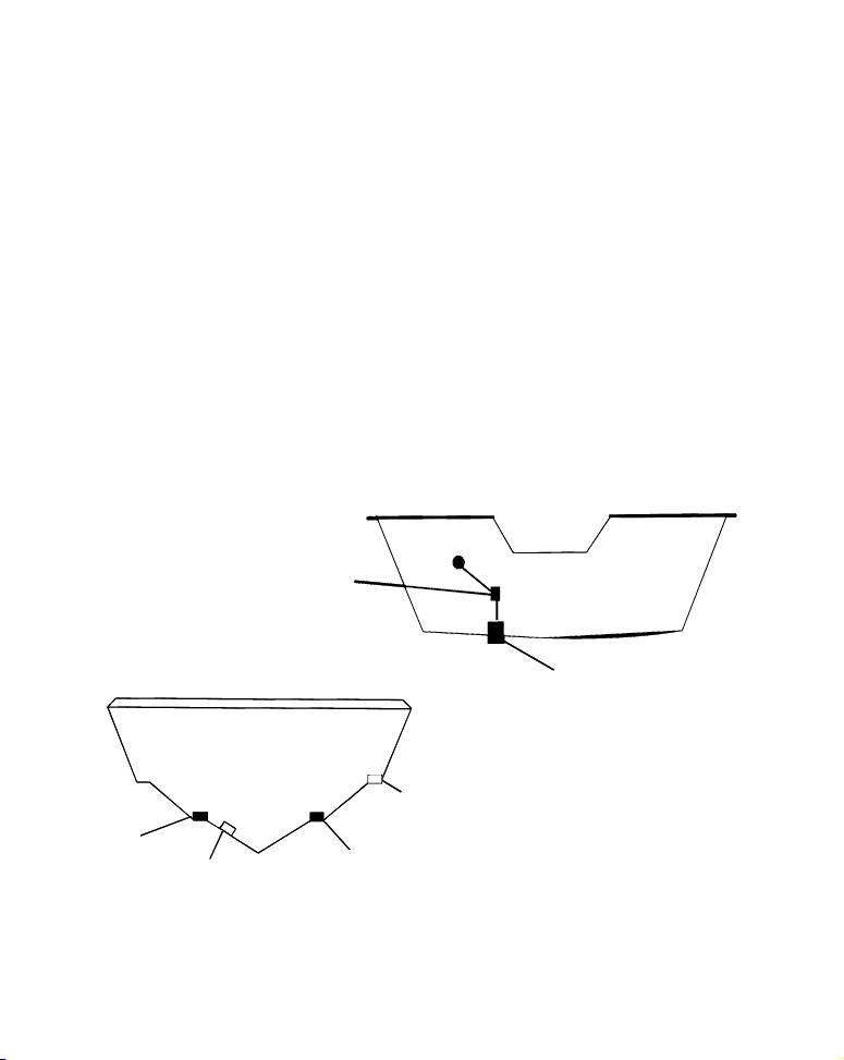
CAUTION: Clamp the transducer cable to transom near
the transducer. This will help
revent the transducer from
entering the boat if it is
knocked off at high speed.
Good location
Good
location
Poor angle
Good and poor transducer locations.
Poor location
Good location
3
Page 10
How low should you go?
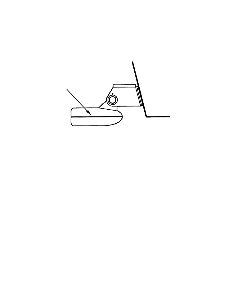
For most situations, you should install your Skimmer transducer so
that its centerline is level with the bottom of the boat hull.
This will usually give you the best combination of smooth water flow
and protection from bangs and bumps.
Transducer
centerline
Align transducer centerline with hull bottom.
Transom
Hull bottom
However, there are times when you may need to adjust the transducer
slightly higher or lower. (The slots in the mounting brackets allow you
to loosen the screws and slide the transducer up or down.) If you frequently lose bottom signal lock while running at high speed, the transducer may be coming out of the water as you cross waves or wakes.
Move the transducer a little lower to help prevent this.
If you cruise or fish around lots of structure and cover, your transducer
may be frequently kicking up from object strikes. If you wish, you may
move the transducer a little higher for more protection.
There are two extremes you should avoid. Never let the edge of the
mounting bracket extend below the bottom of the hull. Never let the
bottom – the face – of the transducer rise above the bottom of the hull.
Transom Transducer Assembly And Mounting
The best way to install these transducers is to loosely assemble all of the
parts first, place the transducer's bracket against the transom and see if
you can move the transducer so that it's parallel with the ground.
4
Page 11
The following instructions sometimes vary depending on the mounting
bracket that came with your transducer. Single-frequency Skimmers come
with a one-piece stainless steel bracket, while dual-frequency Skimmers
come with a two-piece plastic mounting bracket. Use the set of instructions that fits your model.
1. Assembling the bracket.
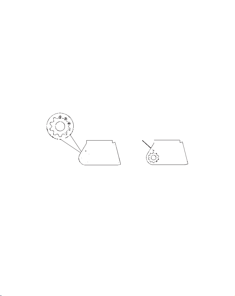
A. One-piece bracket: Press the two small plastic ratchets into the
sides of the metal bracket as shown in the following illustration. Notice
there are letters molded into each ratchet. Place each ratchet into the
bracket with the letter "A" aligned with the dot stamped into the metal
bracket. This position sets the transducer's coarse angle adjustment for a
14° transom. Most outboard and stern-drive transoms have a 14° angle.
Dot
Align plastic ratchets in bracket.
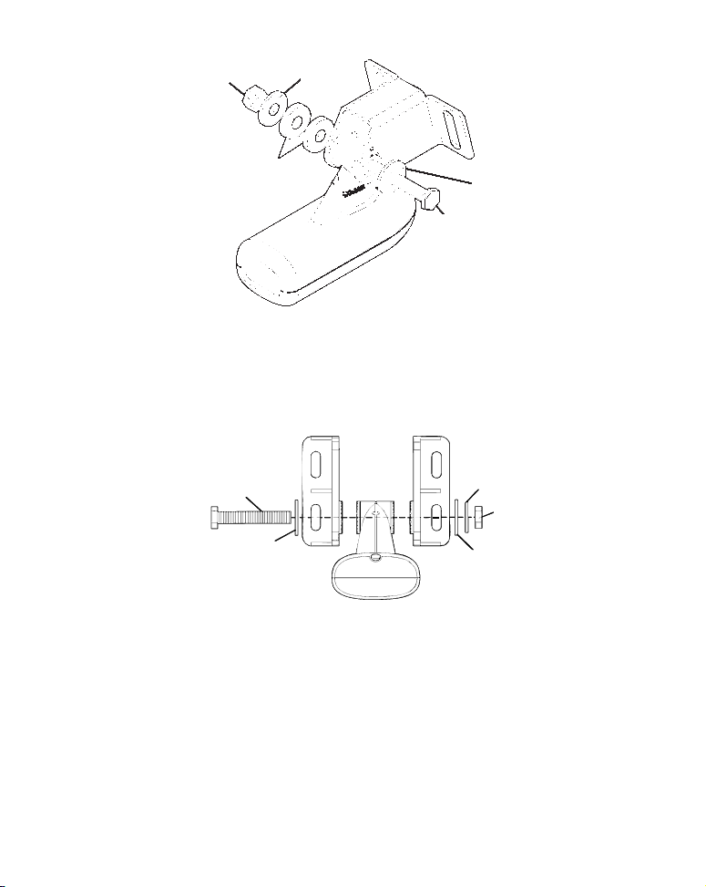
B. Two-piece bracket: Locate the four plastic ratchets in the trans-
ducer's hardware package. Press two ratchets into the sides of the plastic bracket and two on either side of the transducer as shown in the following illustrations. Notice there are letters molded into each ratchet.
Place the ratchets into the bracket with the letter "A" aligned with the
alignment mark molded into the bracket. Place the ratchets onto the
transducer with the letter "A" aligned with the 12 o'clock position on
the transducer stem. These positions set the transducer's coarse angle
adjustment for a 14° transom. Most outboard and stern-drive transoms
have a 14° angle.
5
Page 12
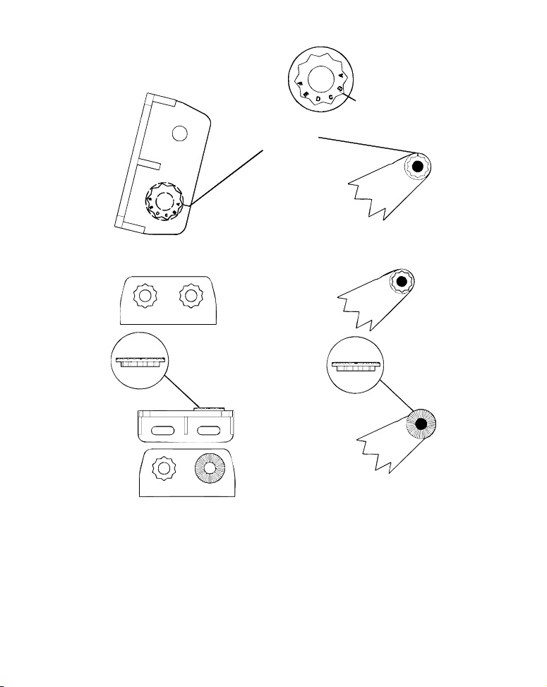
Alig
Alignment
r
positions
Transduce
nment letters
Transducer bracket
Transducer
bracket
Insert and align ratchets.
Transducer
Ratchet
Ratchet
Add ratchets to bracket and transducer.
2. Aligning the transducer on the transom.
To align the transducer to the transom, side the transducer between
the ratchets. Look at the transducer from the side and adjust it so that
its face is parallel to the ground. The alignment letters on either side of
the bracket need be the same.
6
Page 13
If the transducer's face isn't parallel with the ground, remove the
transducer and ratchets from the bracket. Place the ratchets into the
holes in the bracket with the letter "B" aligned with the dot stamped in
the bracket.
Reassemble the transducer and bracket and place them against the
transom. Again, check to see if you can move the transducer so it's parallel with the ground. If you can, then go to step 3A.
3. Assembling the transducer.
A. One-piece bracket: Once you determine the correct position for
the ratchets, assemble the transducer as shown in the following figure. Don't tighten the lock nut at this time.
Position transducer mount on transom and mark mounting holes. Side
view shown, left, and seen from above at right.
7
Page 14
Metal
r
r
Nut
Rubber
washers
washer
Metal washer
Bolt
Assemble transducer and bracket.
B. Two-piece bracket: Once you determine the correct position for
the ratchets, assemble the transducer as shown in the figure in step
2B. Don't tighten the lock nut at this time.
Bolt
Flat washer
Lock washe
Nut
Flat washe
Assemble transducer and bracket.
4. Drilling mounting holes.
Hold the transducer and bracket assembly against the transom. The
transducer should be roughly parallel to the ground. The transducer's centerline should be in line with the bottom of the hull. Don't
let the bracket extend below the hull!
8
Page 15
Mark the center of each slot for the mounting screw pilot holes. You
will drill one hole in the center of each slot.
Drill the holes. For the one-piece bracket, use the #29 bit (for the #10
screws). For the two-piece bracket, use the #20 bit (for the #12 screws).
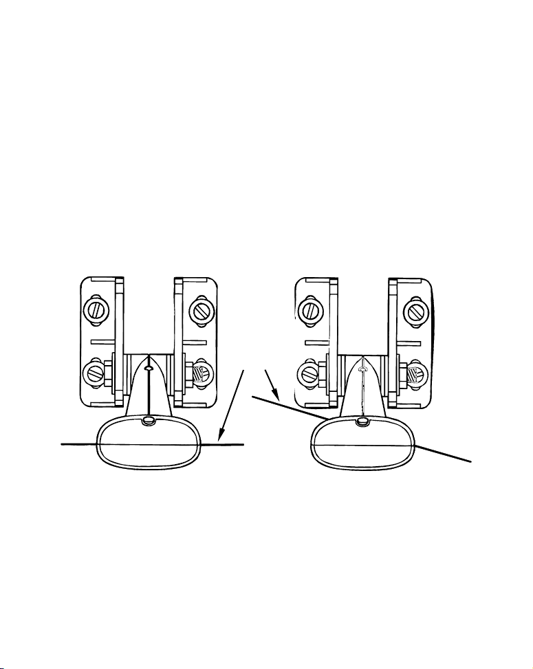
5. Attaching transducer to transom.
Both bracket types: Attach the transducer to the transom. Slide the
transducer up or down until it's aligned properly with the bottom of
the hull as shown in the preceding and following figures. Tighten the
bracket's mounting screws, sealing them with the sealant.
Adjust the transducer so that it's parallel to the ground even if you
have a Deep-"vee" hull. Tighten the nut until it touches the outer
washer, then add 1/4 turn. Don't over tighten the lock nut! If you do,
the transducer won't "kick-up" if it strikes an object in the water.
Bottom
of
hull
Flat-bottom hull Deep-"vee" hull
Align transducer centerline with hull bottom and attach transducer to
transom. Rear view of dual-frequency Skimmer shown.
6. Route the transducer cable through or over the transom to the sonar
unit. Make sure to leave some slack in the cable at the transducer.
9
Page 16

If possible, route the transducer cable away from other wiring on the
boat. Use caution when routing the transducer cable around these
wires.
WARNING:
Clamp the transducer cable to the transom close to the
transducer. This can prevent the transducer from entering the boat if it is knocked off at high speed.
Caution:
If you need to drill a hole in the transom to pass the connector
through, the required hole size be 1". If you drill the hole, make
sure it is located above the waterline. After installation, be sure
to seal the hole with the same marine grade above- or belowwaterline sealant used for the mounting screws.
7. Make a test run to determine the results. If the bottom is lost at
high speed, or if noise appears on the display, try sliding the transducer bracket down. This puts the transducer deeper into the water,
hopefully below the turbulence causing the noise. Don't allow the
transducer bracket to go below the bottom of the hull!
Trolling Motor Bracket Installation
(single-frequency only)
1. Attach the optional TMB-S bracket to the transducer as shown in the
following figure, using the hardware supplied with the transducer.
(Note: The internal tooth washer is supplied with the TMB-S.)
2. Slide the adjustable strap supplied with the TMB-S through the slot
in the transducer bracket and wrap it around the trolling motor. Position the transducer to aim straight down when the motor is in the
water. Tighten the strap securely.
10
Page 17
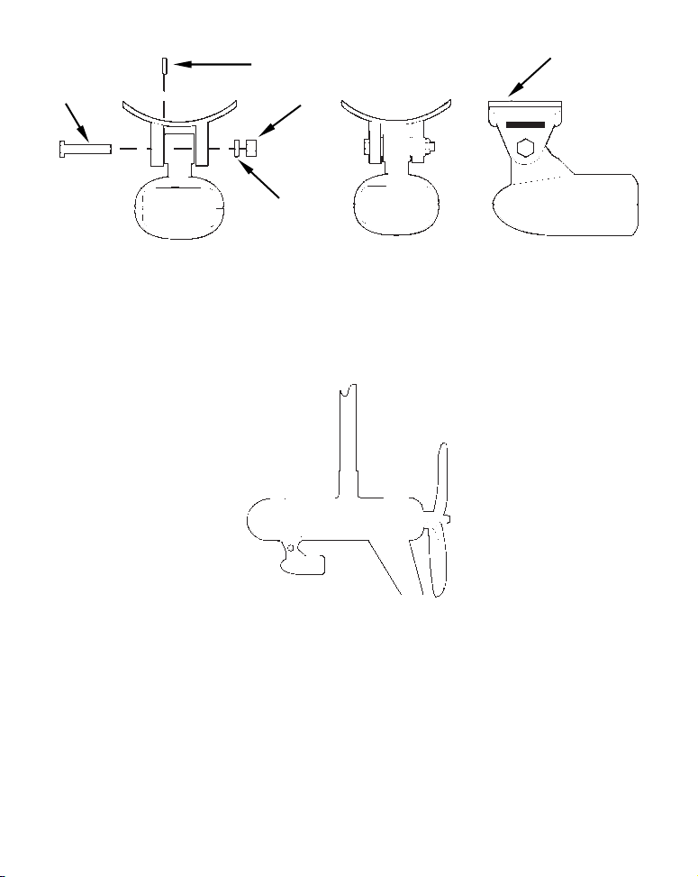
r
TMB-S bracket
Bolt
Internal tooth washer
Nut
Flat washe
Attach motor mounting bracket to transducer.
3. Route the transducer cable alongside the trolling motor shaft. Use
plastic ties (not included) to attach the transducer cable to the trolling motor shaft. Make sure there is enough slack in the cable for the
motor to turn freely. Route the cable to the sonar unit and the transducer is ready for use.
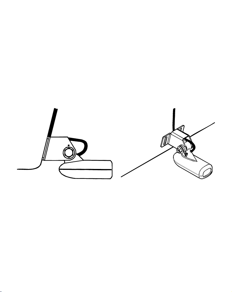
Transducer mounted on trolling motor, side view.
Transducer Orientation and Fish Arches
If you do not get good fish arches on your display, it could be because
the transducer is not parallel with the ground when the boat is at rest
in the water or at slow trolling speeds.
11
Page 18
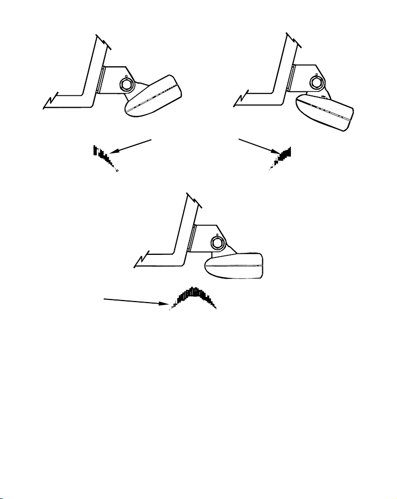
Partial fish arches
Transducer aimed
too far back
Full fish arch
Proper transducer angle
Transducer angles and their effects on fish arches.
Transducer aimed
too far forward
If the arch slopes up – but not back down – then the front of the transducer is too high and needs to be lowered. If only the back half of the
arch is printed, then the nose of the transducer is angled too far down
and needs to be raised.
NOTE:
Periodically wash the transducer's face with soap and water to remove
any oil film. Oil and dirt on the face will reduce the sensitivity or may
even prevent operation.
12
Page 19

Power Connections (permanent mount only)
The unit works from a 12-volt battery system. You can attach the
power cable to your boat's accessory or power buss (or directly to the
battery). If you use an accessory buss but have problems with electrical
interference, attach the power cable directly to the battery. If the cable
is not long enough, splice #18 gauge wire onto it.
CAUTION:
When using
ommend that you shut off the power supply to the power cable
when the unit is not in use. When the unit is turned off but still
connected to a power supply, electrolysis can occur in the power cable plug. This may result in corrosion of the plug body along with
the electrical contacts in the cable and the unit's power socket.
In saltwater environments we recommend you connect the power
cable to the auxiliary power switch included in most boat designs.
If that results in electrical interference, or if such a switch is not
available, we recommend connecting direct to the battery and installing an inline switch. This will let you shut off power to the
power cable when the unit is not in use. When you are not using
the unit, you should always shut off power to the power cable, especially when the power cable is disconnected from the unit.
If possible, keep the power cable away from other boat wiring, especially the engine's wires. This will provide the best isolation from electrical noise. The power cable has two wires, red and black. Red is the
positive lead, black is negative or ground. Make sure to attach the inline fuse holder to the red lead as close to the power source as possible.
the unit in a saltwater environment, we strongly rec-
13
Page 20
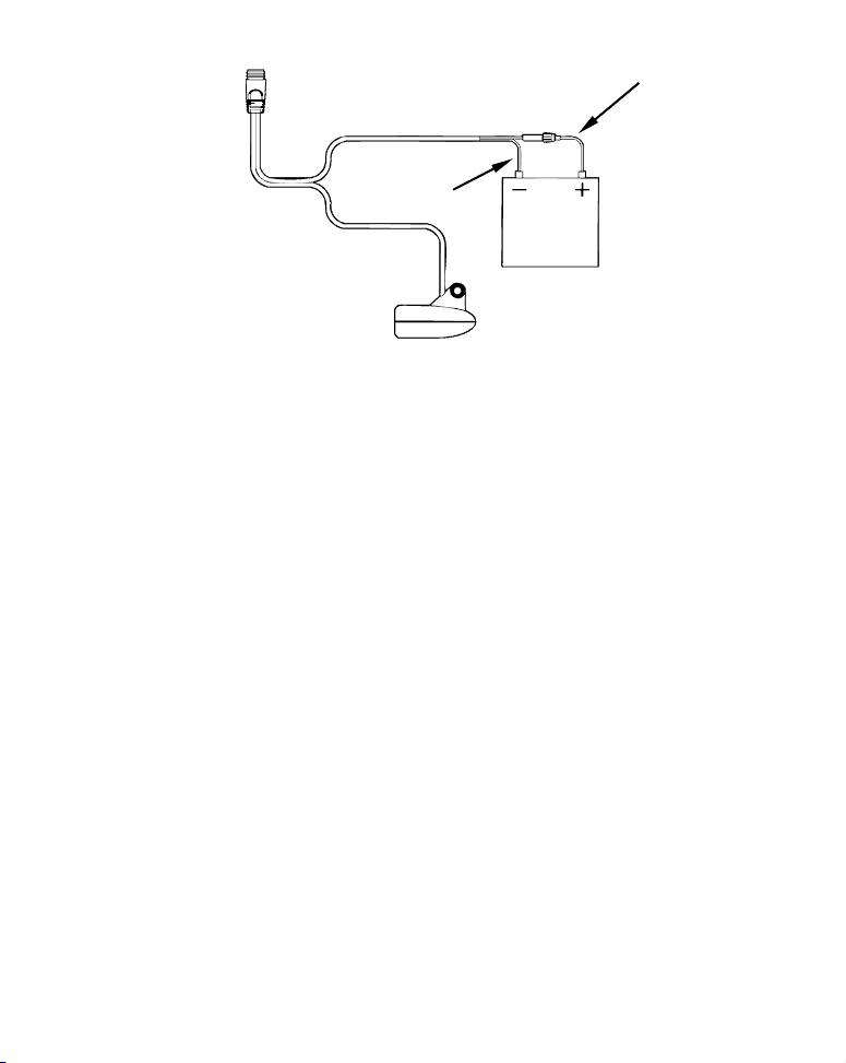
To unit
Black wire
12 volt
battery
Red wire with
3 amp fuse
Power connections for the Cuda 300 sonar unit
(direct battery connection shown).
For example, if you have to extend the power cable to the battery or
power buss, attach one end of the fuse holder directly to the battery or
power buss. This will protect both the unit and the power cable in the
event of a short. It uses a 3-amp fuse.
Caution:
Do not use this product without a 3-amp fuse wired into the
power cable! Failure to use a 3-amp fuse will void your warranty.
This unit has reverse polarity protection. No damage will occur if the
power wires are reversed. However, the unit will not work until the
wires are attached correctly.
Mounting the Sonar Unit: In-Dash, Bracket or Portable
You can install the sonar unit on the top of a dash with the supplied
bracket. This unit can be installed in a dash with the optional FM-6 indash adapter kit. The FM-6 kit includes an instruction sheet, part 9880147-631, which contains a template for cutting out the mounting hole.
This document can be downloaded free from the www.eaglesonar.com
web site.
14
Page 21
Bracket Installation
Recommended tools for this job include: drill, 1" (25.4 mm) drill bit,
screwdriver. Required supplies for this job include: high quality, ma-
rine grade above- or below-waterline caulking compound, three #10
stainless steel screws. Screw length and type should be suitable for the
material on which you intend to mount the bracket.
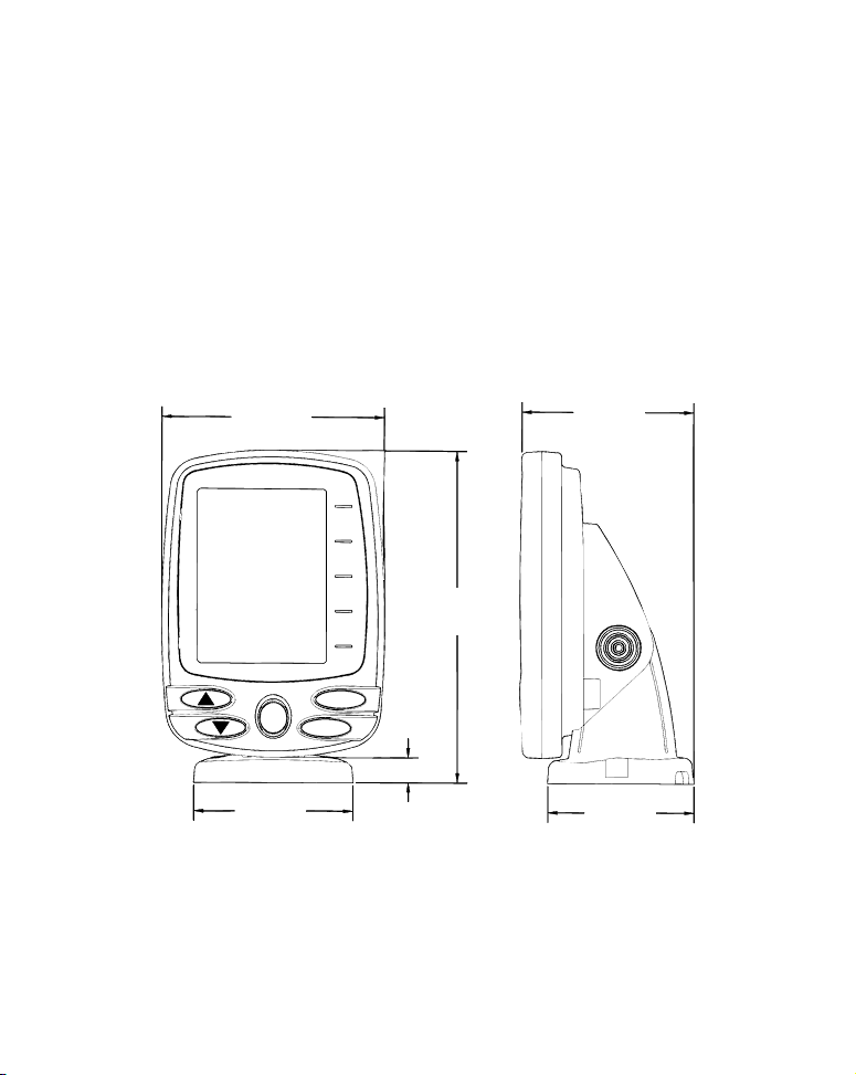
Mount the unit in any convenient location, provided there is clearance
when it’s tilted for the best viewing angle. You should also make sure
there is enough room behind the unit to attach the power/transducer
cable. (See the following drawings, which show the dimensions of a
gimbal-mounted Cuda 300 sonar unit.)
107.5
[4.23]
156
[6.26]
82.7
[3.26]
12.09 [0.48]
76.9
[3.03]
Front view (left) and side view (right) showing dimensions
of the Cuda 300 when mounted on quick release bracket.
Millimeter
[Inch]
70.3
[2.77]
15
Page 22
Holes in the bracket’s base allow wood screw or through-bolt mounting.
You may need to place a piece of plywood on the back side of thin panels to reinforce the panel and secure the mounting hardware.
Drill a 1" (25.4 mm) hole in the dash for the power/transducer and accessory cables. The best location for this hole is immediately under the
gimbal bracket location. This way, the bracket can be installed so that
it covers the hole, holds the cables in position and results in a neat installation. Some customers, however, prefer to mount the bracket to the
side of the cable hole — it's a matter of personal preference.
After drilling the hole, pass the connectors up through the hole from
under the dash. If you wish, you can fill in the hole around the cable with
a good marine caulking compound. (Some marine dealers stock cable hole
covers to conceal the opening.)
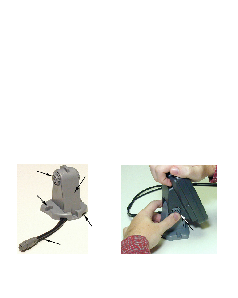
Using the Quick Release Mounting Bracket
These units use a quick release mounting bracket. When you run the
cables through the bracket's cable slots, make sure you allow enough
slack for tilting the unit and attaching the connector. (The snug fit of
the push-on waterproof connector requires some force to attach.)
Ratchet
Screw hole
Power/transducer
cable
Cuda 300 quick release mounting bracket (left). Adjusting the viewing
angle of a display unit (right).
Rear
view
Cable slot
Depress
ratchets to
release
16
Page 23

Attach the unit to the bracket by first connecting the power/transducer
and accessory cables. Then, hold the sonar unit vertically and slide it
onto the bracket from above. (The back of the unit should be touching
the front of the bracket as you lower it into position.) As you push
down, the unit will lock into place with a distinct click.
To adjust the viewing angle, pinch the ratchets with one hand, then tilt
the unit with your other hand. Release the ratchets and the unit locks
into the new position. To dismount the unit for storage, press the ratchets and lift the unit off the bracket.
Portable Sonar Installation
Like many Eagle products, the Cuda 300 sonar is capable of portable
operation. It uses the optional PPP-12 portable power pack.
The PPP-12 package includes the power pack, battery adapter and a portable transducer. The transducer can be stored inside the power pack. The
PPP-12 requires eight AA alkaline batteries. Batteries are not included.
To use a portable power pack, you install the batteries and then attach
the sonar unit to the power pack's bracket. Plug in the
power/transducer cable and you're ready to fish.
The PPP-12 has a quick-release mounting bracket built into the case.
Installing the Batteries
Open the case and lay it flat. (The latch is located below the handle.)
Insert eight "AA" size batteries into the battery adapter and place it in
the battery compartment. Slip the battery cover tabs into the slots in
the case wall, then close the battery cover with the thumb screw.
Plug the cable's power (dog bone-shaped) connector into the socket on
the battery compartment cover. Route the cable's unit connector and
about 6 inches (15.2 cm) of cable through the opening under the sonar
mount. Close the case bottom, using the slot in the case wall to avoid
pinching the cable. Turn the unit over to mount the sonar.
17
Page 24
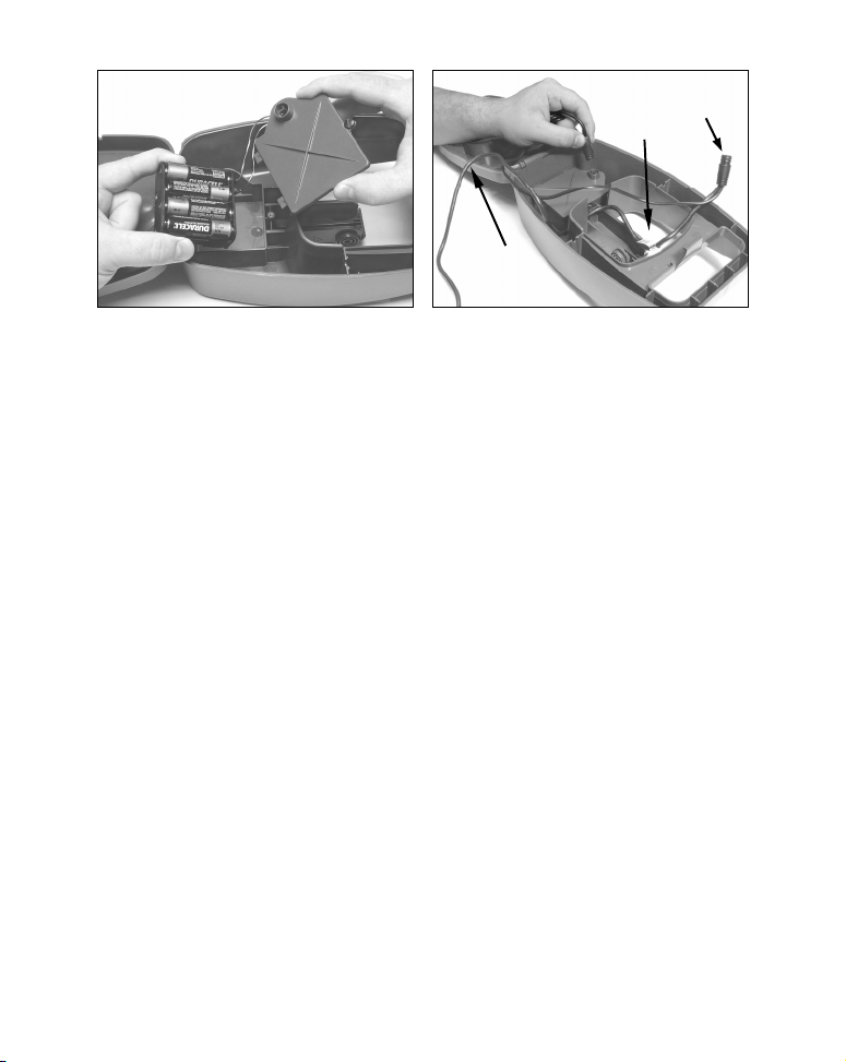
Route this
p
g
cable through
enin
o
Cable slot
in case wall
Install batteries in battery compartment (left).
Attach power cable, and route wires as shown (right).
CAUTION:
When using the sonar in a saltwater environment, we strongly
recommend that you unplug the power connector from the battery socket when the unit is not in use. When the unit is turned
off but still connected to a power supply, electrolysis can occur in
the power cable plug. This may result in corrosion of the plug
body along with the electrical contacts in the cable and the
unit's power socket.
Mounting the Unit
A quick-release mount is built into the top of the portable power pack. To
attach the unit, first plug in the cable connector. Then, hold the sonar unit
vertically and slide it onto the bracket from above. (The back of the unit
should be touching the front of the bracket as you lower it into position.)
As you push down, the unit will lock into place with a distinct click.
To adjust the viewing angle, pinch the quick-release mount's ratchets
with one hand, then tilt the unit with your other hand. Release the
ratchets and the unit locks into the new position. To remove the unit
from the PPP-12, press the ratchets and lift the unit off the bracket.
18
Page 25
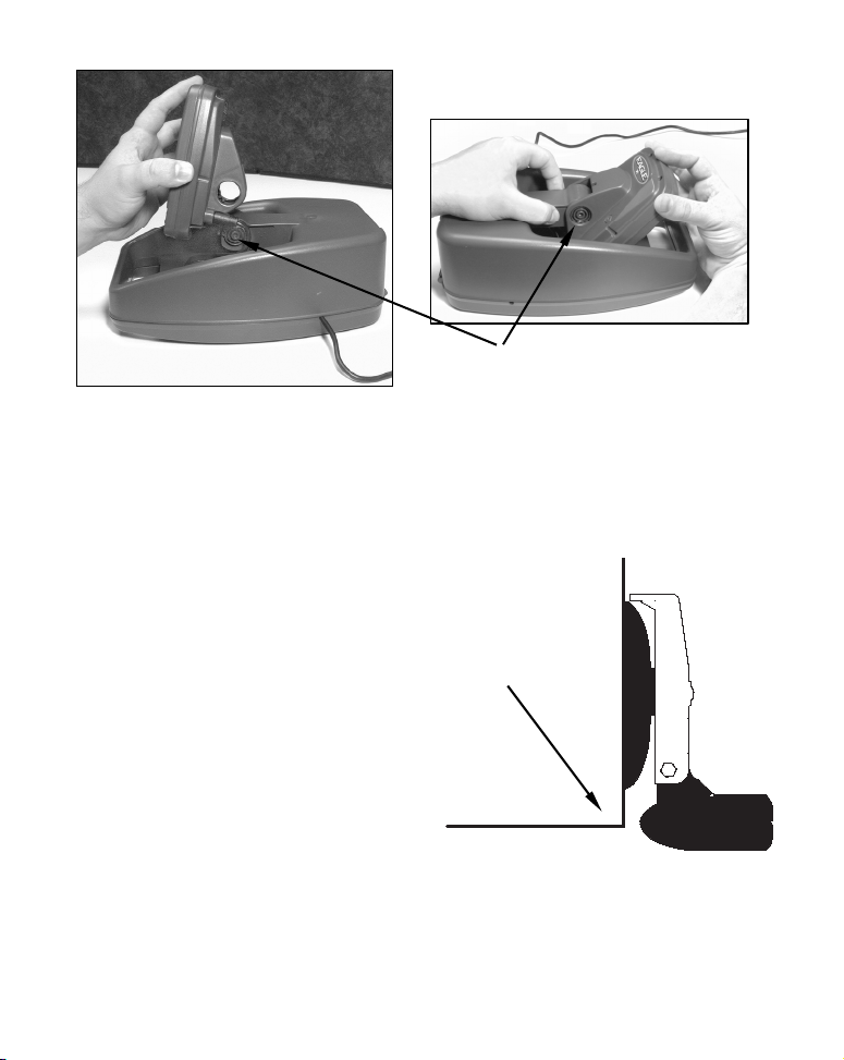
Ratchet
To mount the sonar, slide the unit onto the bracket from above (left).
To adjust the view, press and release spring-loaded ratchets while tilt-
ing the unit (right).
Portable Transducer Assembly
Make sure there is one washer on each side of the transducer, inside the
bracket. Slide the other washer over the end of the bolt and screw on the nut.
Screw the suction cup onto the bracket
using the supplied screw and flat
washer. Tie the nylon cord through the
hole in the top of the bracket. When
using the transducer, tie the other end
Hull
of the nylon cord to the boat. This will
help prevent losing the transducer if it
comes off. Clean the chosen area of
the hull before attaching the suction cup. Locate the transducer on
the hull as shown in the following
figure. Don't let the bracket extend
below the hull, because water pres-
Portable transducer installed on
boat transom.
sure against it can cause the suction
cup to come off at speed.
19
Page 26
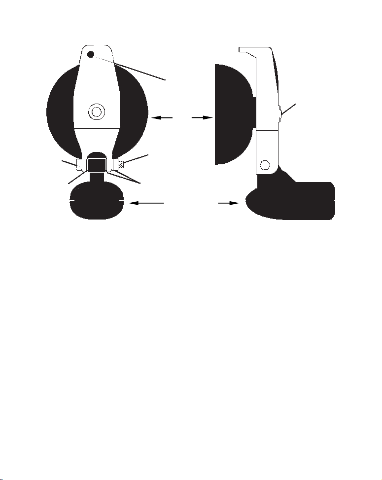
Tie
nylon
cord
here
Screw
Bolt
Washer
Suction
cup
Nut
Washer
Transducer
Portable transducer assembly: rear view (left) and side view (right).
NOTE:
For optimum operation, the portable transducer should be adjusted
so that it is parallel to the ground. For more information on this,
see the segment in the unit's operation manual on Transducer Ori-
entation and Fish Arches.
Moisten the suction cup, then press it onto the hull as firmly as possible. Tie the nylon cord to the boat and set the power pack and sonar unit in
a location for easy viewing. Your portable sonar is now ready for use.
20
Page 27
Operation
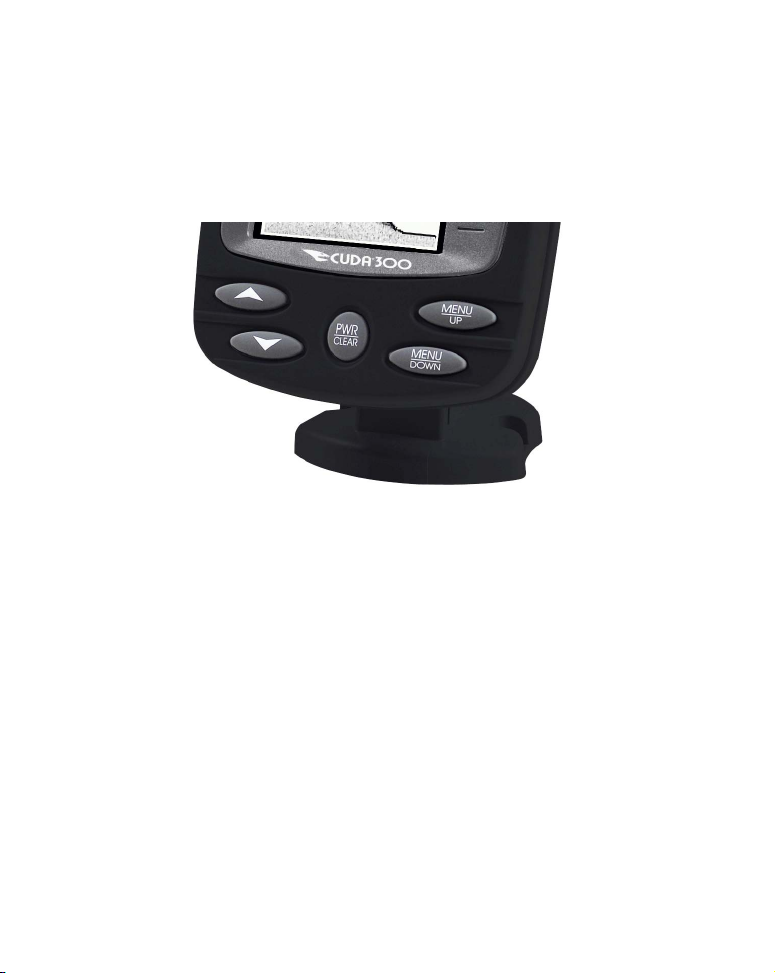
Keyboard Basics
The Cuda 300 has five buttons including, Power/Clear, Menu Up, Menu
Down and two arrow keys.
1
3
Eagle Cuda 300 keyboard.
PWR/CLEAR
Press the
menu selections from the screen.
MENU UP & MENU DOWN
The MENU UP key cycles forward through the menus. The MENU DOWN
key moves backward through the menus. To scroll through the unit's
menus, repeatedly press a
UP & DOWN ARROWS (↑ ↓)
The
PWR key to turn the unit on and off. It also clears menus and
MENU key.
UP and DOWN ARROW keys are used to adjust features and functions.
2
Memory
This unit has an internal backup battery that saves the following user
settings when power is turned off: Units of Measure, Temp Size, Depth
21
Page 28
Size, Fish I.D. mode, Noise Reject mode, Range mode, Zoom, Sensitivity,
p
r
Grayline, Chart Speed, Battery Alarm, Display Contrast, Backlight, Language, Fish Alarm, Battery Alarm and Shallow and Deep alarms.
Display
When the unit is turned, the backlight menu will appear. Use the
ARROW keys to turn the backlight on or off. Press PWR to clear the
menu from the screen.
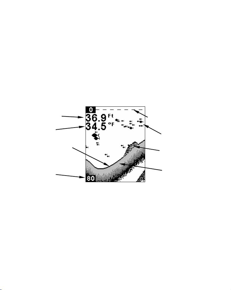
Depth range will be displayed on the left side of the screen. In the following figure, the screen shows a depth range from 0 to 80 feet and the
bottom depth is 36.9 feet, shown by the digital sonar. The water temperature is 34.5° F.
Digital depth
Water Temp
Bottom signal
Depth range
at bottom of
th scale
de
Surface signal
Fish symbols
Structure
or cove
Grayline
®
Full Chart page. Fish I.D. (fish symbols) is on by default.
Full Chart
On the Full Chart page, the bottom signal scrolls across the screen
from right to left. The line at the top of the screen represents the surface. The bottom depth is shown in the upper left-hand corner.
If the transducer with a built-in temperature sensor is connected, the
water temperature also will be shown.
22
Page 29
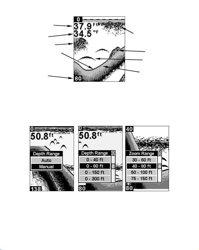
y
Digital depth
p
r
Water Temp
Bait fish
Bottom signal
Depth range
at bottom of
th scale
de
Surface clutter
Structure
or cove
Fish arches
line
®
Gra
Full Chart page with Fish I.D. turned off.
Depth Range
Depth Range has two modes: Automatic and Manual. In auto range
mode, the unit always keeps the bottom displayed in the lower portion
of the screen. If you want to manually select a depth range, you can
override automatic depth range control.
Depth Range menu with Manual setting selected (left). Range Size
menu with 0-80 ft highlighted (center). Zoom Range menu with the 40-
80 foot zoom selected.
23
Page 30

To turn off Auto Depth Range:
1. Repeatedly press MENU until the DEPTH RANGE menu appears. Press ↓
to select MANUAL, then press MENU UP to display the RANGE SIZE menu.
2. Use the arrow keys to select a desired depth range. Press
PWR to
clear the menu from the display.
Zoom
The zoom feature enlarges all images on the screen by doubling the size
of the echoes (a 2X zoom).
To turn on the Zoom feature:
1. Press the MENU key until the ZOOM menu appears. Press ↑ to select
ON, then press PWR to clear the menu.
You can tell when the display is in Zoom mode because the top depth
scale on the left of the screen will no longer show zero. If the current
range is 0 to 80 feet, turning on the zoom feature will magnify the water
column between 40 feet to 80 feet.
To turn off the zoom feature:
1. Press the MENU key until the ZOOM menu appears. Press ↓ to select
OFF, then press PWR to clear the menu. The top of the depth range scale
returns to zero.
NOTE:
You can select from these zoom size ranges: 0-10, 5-15, 10-20, 15-
30, 20-40, 30-60, 40-80, 50-100, 75-150, 100-200, 150-300, 200-400,
300-600, 400-800, 500-1000, 750-1500 and 1000-2000.
To select a zoom range:
1. Make sure Depth Range is set to manual mode. Press MENU until
ZOOM menu appears. Press ↑ to select ON, then press MENU UP to
the
display the
2. Use the arrow keys to select a desired zoom size. Press
the menu from the display.
ZOOM RANGE menu.
PWR to clear
24
Page 31

Sensitivity
Sensitivity adjusts the way echoes will be displayed on the screen. If
you want to see more detail, try increase sensitivity. If your unit is
picking up a lot of clutter, decrease the sensitivity to reduce the
amount of clutter displayed on the screen.
Sensitivity set to manual mode (left). Sensitivity control bar (right).
To adjust sensitivity in Auto Mode:
1. Press MENU until the SENSITIVITY control bar appears. Press ↑ to increase
the sensitivity,
2. Press
sensitivity level, a tone will sound.
To turn on Manual mode:
1. Repeatedly press Menu to display the Sensitivity menu. Highlight
MANUAL and press PWR to clear the menu.
↓ to decrease it.
PWR to clear the menu. If you reach the maximum or minimum
Grayline®
Grayline® helps you tell the difference between a hard and a soft bottom by coloring weaker sonar returns (soft, muddy or weedy bottom)
with a narrow gray line or no gray line at all. A strong sonar return
(hard bottom) will be displayed as a wide gray line.
25
Page 32

y
Bait
school
Fish
arches
Sensitivity at 71 percent (left). Sensitivity at 100 percent (right).
To change the Grayline level:
1. Press MENU until the GRAYLINE control bar appears.
2. Press
↑ to increase the level of Grayline or press ↓ to decrease it. If
you reach the maximum or minimum level, a tone will sound. Press
PWR to clear the menu.
Thin or no Grayline
®
A small amount of Grayline indicates a soft bottom (left), probably
sand or mud. More Grayline indicates a harder, rocky bottom (right).
Chart Speed
The rate that echoes scroll across the screen is called the chart scroll
speed. The default for this unit is the maximum, 100 percent.
26
Wider
Gra
line
®
Page 33

Chart Speed control bar.
NOTE:
When you are stationary or traveling slowly and using a higher
chart speed, a fish swimming through the sonar signal will be dis-
played as a long line instead of a fish arch. You can counteract this
by decreasing the chart speed to match the speed of your boat,
which will shorten the line, making it look more like a fish arch.
To adjust Chart Speed:
1. Press MENU until the CHART SPEED control bar appears. Press ↑ to increase the speed of the chart. Press ↓ to decrease it.
2. Press
PWR to clear the menu.
Fish I.D.™
The Fish I.D. feature displays fish symbols on the screen in place of the
actual fish echoes. There are three symbol sizes: small, medium and
large. These show the relative size between targets.
To see what's under your boat in maximum detail
turn off Fish I.D. and begin learning to interpret fish arches.
To turn Fish I.D. on/off:
1. Press MENU until the FISH ID menu appears. Press ↓ to select ON/OFF.
2. Press
PWR to clear the menu from the display.
27
, we recommend you
Page 34

Fish
arches
Fish I.D.
symbols
Underwater scene in normal fish arch mode (left). Fish I.D. menu with
the feature turned on (right).
FishTrack™
The FishTrack™ feature shows the depth of a fish symbol when it appears on the display.
To turn on/off FishTrack:
1. Press MENU until the FISH ID menu appears. Press ↑ ↓ to select TRACK
OFF.
or
2. Press
I.D. on, press
PWR. (If you want to turn off FishTrack depths but leave Fish
↓ to select ON, then press PWR.) Remember, Fish I.D.
must be on in order to use the FishTrack feature.
Fish Alarm
The Fish Alarm sounds a tone when a fish symbol appears on the
screen. The Fish I.D. feature must be turned on for fish alarms to work.
To turn on/off the fish alarm:
1. Press MENU until the FISH ALARM menu appears. Press ↑ to select
ON/OFF.
2. Press
PWR to clear the menu from the screen
28
Page 35

Fish ID menu and symbol with FishTrack on (left). Fish Alarm menu
(right).
Depth Alarms
The depth alarms consist of a shallow and a deep alarm. The shallow
alarm sounds an alarm tone when the bottom is shallower than the
alarm's setting. The deep alarm sounds a tone when the bottom is
deeper than the alarm's setting.
Shallow Alarm
To set the shallow alarm:
1. Press MENU repeatedly until SHALLOW ALARM appears.
2. Press
box, then press
↓ to SET VALUE. Use ↑ ↓ to enter the first number in the dialog
DOWN MENU to move to the next digit. Repeat those
steps until the desired depth has been entered in the dialog box. To
move the cursor back to any of the previously entered numbers, press
UP MENU.
3. Press
which will turn on the alarm, then press
PWR to return to the Shallow Alarm menu. Use ↑ to select ON,
PWR to clear the menu. When
the alarm goes off a message will appear and a tone will sound. Press
PWR to silence the alarm.
29
Page 36

To turn off the alarm:
1. Repeatedly press MENU until the SHALLOW ALARM menu appears. Press
↓ to OFF.
2. Press
PWR to clear the menu.
Shallow Alarm Value Dialog box (left). Shallow Alarm menu (right).
Deep Alarm
To set the deep alarm:
1. Press MENU repeatedly until DEEP ALARM appears.
2. Press
Use
MENU
depth has been entered in the dialog box. To move the cursor back to
any of the previously entered numbers, press
3. Press
Press
than the alarm’s setting, an alarm will sound and a message will appear on the screen.
To turn off the alarm:
1. Repeatedly press MENU until the DEEP ALARM menu appears. Press ↓
to OFF. Press PWR to clear the menu.
↓ to SET VALUE. The Deep Alarm Value dialog box will appear.
↓ to enter the first number in the dialog box, then press DOWN
to move to the next digit. Repeat those steps until the desired
UP MENU.
PWR to return to the Deep Alarm menu. Use ↑ to select ON.
PWR to clear the menu. When the bottom depth becomes deeper
30
Page 37

Battery Alarm
To set the Battery alarm:
1. Press MENU repeatedly until BATTERY ALARM appears.
2. Press the
will appear. Input a voltage value between 7 and 18 volts. Use the
keys to enter the first number in the dialog box, then press DOWN
MENU
to move to the next digit. Repeat those steps until the desired
value has been entered in the dialog box. To move the cursor back to
any of the previously entered numbers, press
Low Battery Alarm Value (left). Battery Alarm menu (right).
3. Press PWR to return to the Battery Alarm menu. Use ↑ to select ON,
which will turn on the alarm, then press
voltage value falls below the alarm’s setting, the alarm will sound and
a message will appear on the screen.
To turn off the alarm:
1. Repeatedly press MENU until the BATTERY ALARM menu appears. Press
↓ to OFF.
2. Press
↓ to SET VALUE. The Low Battery Alarm Value dialog box
↑ ↓
UP MENU.
PWR to clear the menu. If the
PWR to clear the menu.
31
Page 38

Noise Reject and ASP™
The ASP™ (Advanced Signal Processing) feature is a noise rejection
system that constantly evaluates the effects of boat speed, water conditions and electrical interference and automatically gives you the best
display possible under most conditions. The ASP feature has three settings — Off, Low and High.
To change the ASP setting:
1. Press MENU until the NOISE REJECTION menu appears. Use ↑ ↓ to select
the desired setting.
2. Press
PWR to clear the menu.
Depth Display
Depth may be displayed in a small, medium or large size, or can be
turned off completely.
To display Depth:
1. Repeatedly press MENU until the DEPTH menu appears. Use ↑ ↓ to select the size of the depth display.
2. Press
PWR to clear the menu.
Depth display set to large (left). Voltage display set to small (right).
32
Page 39

Voltage
The Voltage menu allows you to display battery voltage in a small or
medium size, or can be turned off completely.
To display battery voltage:
1. Repeatedly press MENU until the VOLTAGE menu appears. Use ↑ ↓ to
select the size of the voltage display.
2. Press
PWR to clear the menu.
Temperature Display
Temperature may be displayed in a small or medium size, or can be
turned off completely.
To display Temperature:
1. Repeatedly press MENU until the TEMPERATURE menu appears. Use ↑ ↓
to select the size of the temperature display.
2. Press
PWR to clear the menu.
Units
This unit can show the depth in feet or meters and temperature in Celsius or Fahrenheit.
The Backlight menu with backlight turned on.
33
Page 40

To change units of measure:
1. Press MENU until the UNITS menu appears. Use the arrow keys to select the desired unit of measure.
2. Press the
PWR key to clear the menu.
Backlight
Turning on your unit's backlight will allow you to use it at night.
To turn the backlight on/off:
1. Press MENU repeatedly until the BACKLIGHT menu appears. Press ↑ to
turn the light on or
2. Press
PWR to clear the menu.
↓ to turn it off.
Contrast
The unit’s display contrast is adjustable to suit different lighting conditions. It will help you see the screen from different angles or at various
times of the day.
To adjust the contrast:
1. Press MENU until the CONTRAST control bar appears. To decrease
screen contrast, press ↓. Press ↑ to increase screen contrast.
2. Press the
PWR key to clear the menu.
Contrast control bar (center). Simulator menu (center). Languages
menu with English selected (right).
34
Page 41

Simulator
This unit has a simulator that displays a simulated bottom signal with
fish signals.
To turn on/off the simulator:
1. Repeatedly press MENU until the SIMULATOR menu appears. Press ↑ ↓
to turn it on or off.
2. Press
PWR to clear the menu.
Set Language
This unit's menus are available in 11 languages: English, French, German, Spanish, Italian, Danish, Swedish, Russian, Czech, Dutch and
Finnish.
To select a language:
1. Repeatedly press MENU until the Languages menu appears.
2. Use ↑ ↓ to select the desired language. All menus now appear in the
language you selected. Press
PWR to clear the menu.
Software Information
The Software Information screen shows what version of software your
unit is using.
To show the software information:
1. Press MENU until the SOFTWARE INFORMATION menu appears.
2. Press
PWR to clear the screen.
Reset Options
This command is used to reset all features, options and settings to their
original factory defaults.
To Reset Options:
1. Turn the unit off. Press and hold ↓ and the MENU DOWN key at the
same time while pressing the
2. Release the keys as the unit powers up. The unit will turn on with
factory settings restored.
PWR key.
35
Page 42

Notes
36
Page 43

Table des Matières
Informations Techniques: Cuda™ 300 & Cuda™ 300 Portable............1
Préparations ..............................................................................................3
Outils et Matériel Recommandés ........................................................4
Installation à Travers Coque et Installation sur le Tableau ................7
Assemblage et Montage du Transducteur Sur le Tableau
Arrière....................................................................................................8
Installation Sur Un Moteur A La Traine (Trolling Motor).................15
Orientation du Transducteur et Repérage du Poisson ...................15
Branchements (pour les montages permanents uniquement) .......17
Installation du sondeur : Dans le Tableau de Bord, sur Support
ou Portable...........................................................................................19
Installation sur Support.....................................................................19
Installation Portative .........................................................................22
Installation des Piles ..........................................................................23
Installer l’Appareil..................................................................................24
Assemblage du transducteur portatif ...............................................25
Fonctionnement ................................................................................. 29
Clavier......................................................................................................29
Mémoire ...................................................................................................30
Menus.......................................................................................................30
Affichage ..................................................................................................31
Graphique Entier................................................................................32
Portée en Profondeur ..............................................................................33
Zoom .........................................................................................................34
Sensibilité ................................................................................................35
Grayline®.................................................................................................37
Fish I.D.™................................................................................................40
Fishtrack™ ..............................................................................................42
Alarmes....................................................................................................42
Alarme de Poisson ..............................................................................43
Alarmes de Profondeur.......................................................................43
Alarme de Hauts-Fonds .....................................................................44
i
Page 44

Alarme de Profondeur ............................................................................45
Alarme de l’Alimentation .......................................................................46
Rejet du Bruit et ASP™..........................................................................47
Affichage de la Profondeur.....................................................................47
Affichage de la Température .................................................................48
Tension.....................................................................................................48
Unités.......................................................................................................49
Rétro-éclairage ........................................................................................49
Contraste .................................................................................................49
Simulateur...............................................................................................50
Choisir la Langue....................................................................................51
Informations Système ............................................................................51
Ré-initialisation des Options .................................................................51
ii
Page 45

Informations Techniques: Cuda™ 300 & Cuda™ 300 Portable
Générales
Dimensions
du Boîtier:......................... 5.8" H x 4.3" L x 2.5" P (14.7 cm H x 10.8 cm L
x 6.6 cm P) hermétique, étanche; uti
Affichage:..........................
Film SuperTwist LCD Haute Dé
finition. 3.5"
(8.9 cm) en Diagonale.
Résolution: ....................... 240 pixels (vert.) x 160 pixels (horiz.); 38,400
pixels au total.
Rétro-éclairage: .............. écran rétro-éclairé à incandescence.
Alimentation:................... de 10 à 17 volts DC.
Puissance
Consommée:..................... 170 ma éclairage éteint; 240 ma éclairage al-
lumé.
Mémoire
de Sauvegarde:................ Mémoire intégrée sauvegardant les réglages
du sonar lorsque l’appareil est mis hors tension.
Sonar
Fréquence:........................ 200 kHz.
Transducteur:...................Un transducteur Skimmer
®
accompagne votre
sondeur. Son angle de 20° offre une large détection des poissons allant jusqu'à 60º avec les
réglages de haute sensibilité.
Emetteur:.......................... 800 watts crête à crête; 100 watts RMS.
Capacité de Sondage
en Profondeur:................ 600 pieds (180 mètres). La profondeur sondée
dépend de l'installation et de la configuration
du transducteur, de la composition du fond et
de la nature de l'eau.
1
Page 46

Affichage de la
profondeur: ...................... Affichage continu.
Alarmes audibles:........... Profondeur/hauts-fonds/poisson.
Portée Automatique: ..... Oui, avec des mises à jour instantannées à
l'écran.
Détection Automatique
du Fond: ............................ Oui.
Zoom suivant le Fond:... Oui.
Zoom en Ecran Divisé:.. Oui.
Température
de Surface:........................ Oui, intégrée au transducteur. Capteur de
température ou capteur combo vitesse/temp
externes en option disponibles.
Ce manuel concerne le Cuda™ 300 et le Cuda™ 300 Portable. Ces deux
appareils fonctionnent
de la même manière. La
seule différence entre les
deux est que l’appareil portable comprend un transducteur spécial ainsi
que d’autres accessoires permettant une utilisation portative.
AVERTISSEMENT!
Entreposez votre appareil à une température comprise entre -20°C et
+75°C. Un entreposage ou un fonctionnement prolongés à des températures supérieures ou inférieures à celles indiquées ci-dessus peuvent endommager l’écran de visualisation à cristaux liquides. Ce type
de dégât n’est pas couvert par la garantie. Pour plus d’informations,
veuillez contacter le Service Clientèle de l’entreprise; vous trouverez
les numéros de téléphone correspondants à la fin du manuel.
2
Page 47

Installation du Transducteur
Préparations
Voici la séquence des étapes recommandées pour l’installation de votre
transducteur :
Avertissement:
Nous vous recommandons de lire l'intégralité de cette section
avant de percer des trous dans votre bateau!
1. Déterminez l'emplacement approximatif du sondeur, de façon à pouvoir prévoir comment et où passeront les câbles du transducteur et de
l'alimentation. Cela vous permettra de vous assurez que vous disposez de
suffisamment de longueur de câble pour la configuration désirée.
2. Déterminez l'emplacement approximatif du transducteur et le parcours de son câble.
3. Déterminez l'emplacement de votre batterie ou de toute autre source
d'alimentation, ainsi que le parcours du câble d'alimentation.
4. Installez le transducteur et acheminez son câble vers le sondeur.
5. Acheminez le câble d’alimentation depuis le sondeur vers une source
d’alimentation appropriée et branchez-le.
6. Branchez le câble d’alimentation/transducteur au sondeur et installez
ce dernier sur son support.
Installation
Ces instructions vous permettront de mettre en place votre transducteur
Skimmer
motor - moteur de traîne - ou à l’intérieur d’une coque. Nous vous conseillons de lire attentivement ces instructions avant de procéder à
l’installation de votre matériel. Votre transducteur Skimmer est généralement accompagné d’un support de montage en acier inoxydable une
pièce pour un montage sur le tableau de votre bateau. Le montage pour
un trolling motor consiste en un support plastique en une seule pièce,
accompagné d'une courroie ajustable.
®
sur un travers (sonde pour tableau arrière), sur un trolling
3
Page 48

Ces supports de montage aident à éviter l'endommagement du transducteur dans le cas où ce dernier heurterait un objet pendant la marche du
bateau. Si le transducteur est effectivement touché, le support peut ainsi
facilement être repositionné sans outils.
En fonction des connecteurs de votre sondeur, il est possible que le câble
de votre transducteur soit également rattaché au câble d’alimentation. Si
c’est le cas, assurez-vous de bien installer le transducteur en premier,
avant de brancher le câble d’alimentation à une source d’alimentation.
Reportez-vous aux intructions de branchement du câble d’alimentation
plus loin dans ce manuel.
Lisez soigneusement ces instructions avant de procéder à l’installation
du transducteur. Déterminez quelle méthode d'installation convient le
mieux à votre embarcation. Soyez très prudent si vous installez le
transducteur à l'intérieur de la coque, car une fois en place avec
l'époxyde, le transducteur ne peut généralement pas être déplacé ou
retiré. Rappelez-vous que l’installation du transducteur consti-
tue la partie la plus critique de l’installation d’un sonar.
Outils et Matériel Recommandés
Si vous choisissez de faire passer le câble par le tableau arrière, vous aurez besoin d’une mèche de diamètre 25 mm. Un montage sur le tableau
nécessite l’utilisation d’un composé de calfatage de haute qualité marine
au-dessus et en-dessous de la ligne de flottaison.
REMARQUE:
Les types d’installations suivants nécessitent également les outils et
matériaux recommandés suivants (ces matériaux ne sont pas fournis):
Installation d’un transducteur à fréquence unique sur le tableau arrière
Outils recommandés: deux clefs universelles (à ouverture variable), perceuse, mèche #29 (3,5mm), tournevis à tête plate. Matériel: aucun.
Installation d’un transducteur à fréquence unique sur un trolling motor
Outils: Deux clefs universelles, tournevis à tête plate. Matériel: attaches
plastiques pour les câbles.
4
Page 49

Sélectionner l'emplacement du transducteur
1. L'emplacement choisi doit constamment se trouver dans l'eau, et cela à
n'importe quelle vitesse.
2. Le transducteur doit être installé à un endroit où le débit de l’eau sera
constamment le plus régulier possible. Si le transducteur n’est pas placé
au niveau d’une eau en mouvement uni et constant, les perturbations
causées par les bulles d’air et les turbulences se traduiront à l’écran du
sondeur par des interférences (apparition de lignes et de points) dès que
le bateau se mettra en mouvement.
REMARQUE:
Certains bateaux en aluminium, avec des virures ou des membrures
externes à la coque, créent de grandes quantités de turbulences lorsqu’ils sont lancés à grande vitesse. Ces bateaux sont généralement
équipés de puissants moteurs hors-bord capables de les propulser à
des vitesses supérieures à 35 mph (55km/h environ). Sur ce genre de
bateaux, le transducteur sera généralement le mieux installé entre
les membrures les plus proches du moteur.
3. Le transducteur doit si possible être orienté de façon à ce que son endroit pointe directement vers le bas. Pour les installations à l'intérieur de
la coque: Beaucoup de bateaux de pêche populaires possèdent une quille
plate qui constitue une bonne surface de montage. Sur les coques en V,
essayez de placer le transducteur à un endroit où l'inclinaison est égale
ou inférieure à 10°.
Inclinaison de moins de 10°
Quille plate
Coque en V à fond plat (gauche); Coque en V (droite). Un transducteur-
nacelle est illustré ici, mais le principe est le même pour les transduc-
teurs Skimmers installés dans la coque.
Lisses
5
Page 50

4. Si le transducteur est installé sur le tableau, assurez-vous qu’il
A
n’entravera pas le remorquage ou le halage du bateau. De plus, ne
l’installez pas à moins d’un pied (30 centimètres environ) du plus bas
élément du moteur. Cette précaution permettra de limiter les interférences causées par l’action des hélices (bulles d’air).
5. Si possible, évitez de faire passer le câble du transducteur à proximité
d’une autre installation électrique du bateau. Des bruits électriques parasites provenant du câblage du moteur, des pompes de drain et des aérateurs peuvent en effet être traduits à l’écran. Soyez prudent lorsque vous
faites passer le câble du transducteur à proximité de ces fils électriques.
VERTISSEMENT: Fixez le
câble du transducteur au
tableau à proximité du transducteur. Ceci empêchera le
transducteur d'entrer sur le
bateau s'il est arraché à
grande vitesse.
Mauvaise Position
Bonne
Position
Mauvais angle
Bonnes et mauvaises positions d’installation du transducteur
Bonne Position
Bonne Position
À quel niveau devez-vous installer le transducteur?
Dans la plupart des cas, nous vous conseillons d’installer votre transducteur Skimmer de façon à ce que sa ligne médiane soit au même niveau que le fond de la coque du bateau. Cela vous assurera généralement un débit régulier de l’eau et une protection contre les chocs.
6
Page 51

q
Ligne
médiane du
transducteur
Tableau
Alignez la ligne médiane du transducteur avec le fond de la coque.
Fond de la Co
ue
Néanmoins, il sera parfois nécessaire de réajuster la position du transducteur, vers le haut ou vers le bas. (Les fentes présentes sur les supports de
montage vous permettent de désserrer les vis et de faire glisser le transducteur). Si vous perdez fréquemment le signal de fond lorsque vous naviguez à grande vitesse, le transducteur sort probablement de l’eau au
contact de vagues ou lorsque vous traversez un sillage. Déplacez légèrement le transducteur vers le bas pour empêcher que cela se reproduise.
Si vous vous déplacez ou que vous pêchez dans des zones riches en édifices rocheux, abris et/ou structures, votre transducteur peut fréquemment
remonter du fait d'à-coups ou de contacts avec ces obstacles. Si vous le
souhaitez, vous pouvez le remontez légèrement pour plus de protection.
Il existe deux extrêmes que nous vous conseillons d’éviter. La première est
de ne jamais laisser le bord du support de montage descendre plus bas que
le fond de votre coque. La deuxième est de ne jamais laisser le fond –
l’endroit – du transducteur s’élever plus haut que le fond de votre coque.
Installation à Travers Coque et Installation sur le Tableau
Dans le cas d'une installation dans la coque, le transducteur est collé à
l'intérieur de la coque par de la résine époxyde. Le signal "ping" du sonar
passe à travers la coque puis se propage dans l'eau. Cela diffère d'une
installation à travers coque classique où un trou est découpé dans la co
que et un transducteur spécialement conçu est monté à l'aide d'un passe
7
Page 52

coque et d'un écrou. Dans ce cas le transducteur est en contact direct avec
l'eau.
Généralement, l’installation du transducteur à l'intérieur de la coque
donne d’excellents résultats à grande vitesse, et une bonne, voir excellente, lecture en profondeur.
Il n’existe aucun risque de choc avec des objets flottants. Le transducteur
ne peut pas être heurté ou arraché lors de la mise à quai ou du chargement sur une remorque.
L’installation à l’intérieur de la coque présente cependant quelques inconvénients. Tout d’abord, il arrive qu’il y ait perte de sensibilité, même
au travers des meilleures coques. Ce phénomène varie d’une coque à une
autre, et même entre différentes installations sur une même coque. Ce
phénomène est du aux différentes structures et constructions de la coque.
De plus, l’angle du transducteur ne peut pas être ajusté pour un repérage
optimal des poissons (visibles à l’écran sous forme d’arcs). L'impossibilité
de réglage de l'angle peut particulièrement poser problème pour les coques dont l’avant se soulève à l’arrêt ou à vitesses lentes.
Troisièmement, un transducteur NE PEUT PAS émettre à travers des
coques en bois ou en métal. Ces coques recquièrent une installation sur
tableau arrière ou une installation à travers la coque classique.
Enfin, si votre transducteur Skimmer possède un capteur de température
intégré, il n'affichera que la température du fond de cale et non pas la
température de surface de l'eau.
Suivez les procédures d'essai listées dans la section concernant l'installation à l'intérieur de la coque pour déterminer si vous pouvez émettre à
travers votre coque de manière satisfaisante.
Assemblage et Montage du Transducteur Sur le Tableau Arrière
La meilleure façon d’installer ce type de transducteur est tout d’abord
d’assembler toutes les pièces qui le composent, puis de placer le support
du transducteur sur le tableau en vous assurant que vous puissiez dépla-
8
Page 53

cer le transducteur de façon à ce qu’il reste parallèle au sol.
1. Assemblage du support. Enfoncez les deux petits rochets en plastique sur les côtés du support en métal, comme le montre l’illustration suivante. Remarquez que des lettres sont gravées sur chaque rochet. Placez
chaque rochet avec la lettre "A" alignée sur la marque (point) présente
sur le support en métal.
Cette position ajuste l’angle du transducteur pour un tableau de 14°. La
plupart des tableaux de hors-bord et de bateaux propulsés par l'arrière
possèdent un angle de 14°.
Point
Placez les rochets en plastique sur le support.
2. Aligner le transducteur sur le tableau. Glissez le transducteur entre
les deux rochets. Glissez temporairement le boulon à travers l’assemblage
et maintenez le tout contre le tableau. En regardant le transducteur de côté,
vérifiez qu’il puisse être ajusté de façon à être parallèle au sol. Si c’est le cas,
alors la position "A" est la bonne pour votre coque.
Si le transducteur n’est pas parallèle au sol, retirez le transducteur et
les rochets du support. Placez les rochets avec la lettre "B" alignée avec
la marque présente sur le support.
Assemblez à nouveau le transducteur et le support et placez-les contre le
tableau. De nouveau, vérifiez que le transducteur puisse être déplacé
afin d’être parallèle au sol. Si c’est le cas, reportez-vous à l’étape 3. Sinon, répétez l’étape 2 en utilisant une lettre d’alignement différente jus-
9
Page 54

qu'à ce que le transducteur soit correctement placé contre le tableau.
Rochets
Insérez le boulon et vérifiez la position du transducteur contre le tableau.
3. Assemblage du transducteur. Une fois que vous aurez déterminé
la position correcte des rochets, assemblez le transducteur et le support
comme le montre l’image suivante. Ne resserrez pas encore l’écrou
autobloquant.
10
Page 55

Rondelle
Écrou
Rondelles en
caoutchouc
en métal
Rondelle en
métal
Boulon
Assemblez le transducteur et le support.
4. Perçage. Maintenez l’assemblage du support et du transducteur
contre le tableau. Le transducteur doit être approximativement parallèle au sol. La ligne médiane du transducteur doit être au même niveau
que le fond de la coque. Ne faites pas dépasser le support plus bas que
le fond de la coque!
Marquez sur le tableau l’emplacement du centre de chaque fente pour
le montage des vis. Vous percerez un trou à chacune de ces positions.
Percez les trous. Utilisez pour cela la mèche #29 (pour les vis #10).
11
Page 56

Tableau
arrière
Tableau
arrière
Positionnez le transducteur contre le tableau et marquez
l’emplacement des trous. Vue de côté, à gauche, et vue du dessus, à
droite.
5. Fixation du transducteur au tableau. Retirez le transducteur du
support et ré-assemblez le tout en faisant passer le câble dans le support
et par dessus le boulon, comme l’illustrent les figures ci-dessous.
Faites passer le câble par dessus le boulon puis dans le support. Vue de
côté (gauche), et vue du dessus (droite).
12
Page 57

Fixez le transducteur au tableau. Faites glisser le transducteur vers le
haut ou vers le bas jusqu’à ce qu’il soit correctement aligné avec le fond
de la coque, comme l'illustrent les figures suivantes et précédentes. Resserrez les vis du support et enduisez-les d’un produit de calfatage.
Ajustez la position du transducteur de façon à ce qu’il soit parallèle au sol
puis resserrez l’écrou jusqu’à ce qu’il entre en contact avec la bague se
trouvant le plus à l’extérieur. Resserrez alors encore d’un quart de tour.
Ne serrez pas trop l’écrou autobloquant! En effet, le transducteur ne
pourrait alors plus "rebondir" s'il heurtait un objet dans l’eau.
Fond de
la coque
Coque à fond plat Coque en V prononcé
Alignez la ligne médiane du transducteur avec le fond de la coque puis
fixez-le au tableau.
6. Faites passer le câble du transducteur à travers ou par dessus
le tableau arrière jusqu’à votre sondeur. Assurez-vous que le câble
du transducteur ne soit pas trop tendu, donnez-lui du mou. Si possible,
évitez de faire passer le câble du transducteur à proximité d’une autre
installation électrique sur le bateau. Des bruits électriques parasites provenant du câblage du moteur, des pompes de drain, de radio VHF (hyperfréquence) et des aérateurs peuvent en effet être traduits à l’écran. Soyez
prudent lorsque vous faites passer le câble du transducteur à proximité
de ces fils électriques.
13
Page 58

AVERTISSEMENT:
Fixez le câble du transducteur au tableau à proximité du
transducteur. Ceci empêchera le transducteur d'entrer
sur le bateau s'il est arraché à grande vitesse.
Si vous devez percer un trou dans le tableau pour y faire passer le raccord du câble, la taille du trou requise est de 16 mm (5/8"). (Si vous avez
l'intention d'acheminer un câble supplémentaire pour un capteur de vitesse ou de température à travers le même trou, vous aurez besoin d'une
mèche de 25,4mm de diamètre à la place.)
Attention:
Si vous percez un trou dans le tableau pour le passage du câble,
assurez-vous qu’il se situe bien au-dessus de la ligne de flottaison.
Une fois l’installation terminée, comblez convenablement le trou
avec le même produit d'étanchéité que celui utilisé pour les vis.
7. Procédez à un essai pour tester le matériel et visualiser les
résultats. Si vous perdez le signal du fond à grande vitesse, ou si des
interférences apparaissent à l’écran, essayez de faire glisser le support
du transducteur vers le bas. Le transducteur se retrouve ainsi positionné plus profondément dans l’eau, et avec un peu de chance, il se
trouvera au-dessous des turbulences à l’origine des interférences. Ne
faites jamais descendre le support plus bas que le fond de la coque!
Boulon
Rondelle dentée
Ecrou
Support TMB-S
Rondelle
plate
Fixez le support de montage du moteur au transducteur.
14
Page 59

Installation Sur Un Moteur A La Traine (Trolling Motor)
1. Fixez le support TMB-S au transducteur, comme l’illustre la figure
suivante, en utilisant le matériel fourni avec le transducteur (Remarque:
la rondelle dentée est fournie avec le TMB-S.)
2. Glissez la courroie de serrage fournie avec le TMB-S dans la fente du
support et enroulez-la autour du moteur. Positionnez le transducteur de
façon à ce que sa face se retrouve vers le bas quand le moteur sera à
l’eau. Resserrez bien la courroie.
3. Faites passer le câble du transducteur le long de l’axe du moteur. Utilisez des cordons en plastique (non fournis) pour attacher le câble du
transducteur à l’arbre du moteur. Assurez-vous que le câble soit suffisamment détendu pour que le moteur puisse tourner librement. Acheminez le câble jusqu’au sondeur, le transducteur est alors prêt à l’emploi.
Transducteur installé sur un moteur à la traîne, vue de côté.
Orientation du Transducteur et Repérage du Poisson
Si vous ne visualisez pas de bons repérages de poissons à l’écran (arcs), il
est possible que le transducteur ne soit pas parallèle au sol lorsque le
bateau est à l’arrêt ou marche à vitesse très lente.
Si seule la deuxième partie de l’arc de repérage est visible (inclinaison
vers le bas de gauche à droite), alors l’avant du transducteur est trop
haut et doit être descendu. Si seule la première partie de l’arc de
repérage est visible (arrière du signal, inclinaison vers le haut de gau-
15
Page 60

che à droite), alors l’avant du transducteur est trop bas et doit être relevé.
Repérages partiels
de poisson
Transducteur
orienté trop en
arrière
Arc de repérage
complet
Transducteur
orienté trop en
avant
Orientation appropriée
Orientations du transducteur et leurs conséquences sur les arcs de
poissons.
REMARQUE:
Nettoyez périodiquement la surface du transducteur avec de l’eau
et du savon pour retirer toute pellicule d’huile susceptible de se
16
Page 61

déposer. L’huile et la saleté qui peuvent se déposer à la surface du
transducteur réduiront sa sensibilité et peuvent également altérer
son fonctionnement.
Branchements
(pour les montages permanents uniquement)
L’appareil est alimenté par une batterie 12 Volts. Vous pouvez relier le
câble d'alimentation à la barre accessoire ou d’alimentation de votre bateau (ou directement à la batterie). Si vous utilisez une barre accessoire
et que vous rencontrez des problèmes d’interférences électriques, reliez
directement le câble d’alimentation à la batterie. Si le câble fourni n’est
pas assez long, raccordez-y un fil isolé de calibre #18.
ATTENTION:
Lorsque vous utilisez l’appareil en milieu salé, nous vous recommandons fortement de débrancher le câble de sa source
d’alimentation lorsque l’appareil est éteint. Lorsque l’appareil est
éteint mais qu’il reste connecté à une source d’alimentation, un phénomène d’électrolyse peut survenir au niveau de la fiche du câble
d’alimentation. Ceci peut entraîner une corrosion de la fiche ainsi
que des contacts électriques du câble et de la prise du sondeur.
En milieu salé, nous vous recommandons de brancher le câble à
l’interrupteur auxiliaire présent à bord de la plupart des bateaux.
Si vous rencontrez des problèmes d’interférences électriques, ou si
un tel interrupteur n’est pas disponible, nous vous recommandons
de brancher le câble directement à la batterie et d’installer un interrupteur en ligne. Cela vous permettra de couper le courant au
niveau du câble d’alimentation lorsque vous n’utiliserez pas
l’appareil. Lorsque vous n’utilisez pas l’appareil, vous devriez toujours couper le courant au niveau du câble d’alimentation, surtout
quand celui-ci n’est pas branché au sondeur.
17
Page 62

Vers le
sondeur
Fil noir
Batterie
12 volts
Fil rouge avec
fusible
Branchements du sondeur Cuda 300 (ici, branchement direct à la batte-
rie).
Si possible, éloignez le câble d’alimentation de tout autre installation
électrique du bateau, particulièrement celle du moteur. Cette précaution
fournira une meilleure isolation aux interférences électriques. Le câble
d’alimentation est composé de deux fils, un rouge et un noir. Le fil rouge
est positif, le fil noir est négatif. Assurez-vous que le porte-fusible soit
relié au fil rouge aussi près que possible de la source d’alimentation.
Par exemple, si vous devez brancher le câble d’alimentation à la batterie ou
à la barre d’alimentation, reliez une extrémité du porte-fusible directement
à l'une de ces dernières. Ceci protégera à la fois le sondeur et le câble
d’alimentation en cas de court-circuit. Le fusible utilisé est de 3 Ampères.
Attention:
N'utilisez jamais ce produit sans qu'un fusible de 3 ampères ne
soit branché au câble d'alimentation! Le manquement à l'utilisation d'un fusible de 3 ampères annulera votre garantie!
Cet appareil est équipé d’une protection à la polarité inverse. Il ne subira
aucun dommage si les fils électriques sont branchés à l’envers. Cependant, l’appareil ne fonctionnera pas tant que les fils ne seront pas correctement branchés.
18
Page 63

Installation du sondeur : Dans le Tableau de Bord, sur Support
ou Portable
Vous pouvez installer le sondeur sur votre tableau de bord avec le support fourni. Cet appareil peut également être monté dans le tableau de
bord à l'aide du kit adaptateur FM-6 en option. Le kit FM-6 inclut une
feuille d'instructions, partie numéro 988-0147-631, qui comprend un gabarit pour le découpage du tableau. Ce document peut être téléchargé
depuis notre site internet www.eaglesonar.com.
Installation sur Support
Les outils recommandés pour ce travail incluent: perceuse, mèche de
25,4mm de diamètre (1"), tournevis. Matériel requis: composé de calfatage
de haute qualité marine eu-dessus et en-dessous de la ligne de flottaison,
trois vis en acier inoxydable #10. Le type et la longueur des vis devraient
convenir au matériau sur lequel vous comptez monter le support.
Installez l’appareil à un endroit pratique et accessible, et assurez-vous qu’il
soit possible de l’incliner de façon à obtenir le meilleur angle de visibilité.
Assurez-vous également qu'il soit possible de relier les câbles d’alimentation
et du transducteur derrière l’appareil. (Consultez les figures suivantes illustrant les dimensions d'un sondeur Cuda 300 monté sur support.)
Les orifices à la base du support permettent l’insertion de vis à bois ou
de boulons. Au besoin, posez du contre-plaqué sur l’arrière des panneaux minces pour renforcer le tableau de bord et sécuriser le matériel
de montage.
Percez un trou de 25,4 mm (1") dans le tableau de bord pour le passage
du câble d'alimentation et du transducteur, et des câbles accessoires. Le
meilleur emplacement pour ce trou se situe directement en dessous du
support de montage. De cette façon, le support peut recouvrir le trou et
retenir les câbles, pour une installation soignée. Certains clients préfèrent cependant installer le support à proximité du trou prévu pour le
passage des câbles — c’est une question de préférence.
19
Page 64

107.5
[4.23]
12.09 [0.48]
76.9
[3.03]
Vues de face (gauche) et de côté (droite) illustrant les dimensions du
Cuda 300 monté sur un support à dégagement rapide.
156
[6.26]
Millimètres
[Pouces]
82.7
[3.26]
70.3
[2.77]
Faites ensuite passer les raccords par le trou, depuis le dessous du tableau de bord, vers le haut. Si vous le souhaitez, vous pouvez combler le
trou au moyen d’un bon produit de calfatage marin (certains commerçants vendent des caches pour dissimuler l’ouverture.)
Utiliser le Support de Montage à Dégagement Rapide
Ces appareils utilisent un support de montage à dégagement rapide.
Lorsque vous faites passer les câbles dans les fentes du support, assurezvous de leur donner suffisamment de mou pour pouvoir incliner le boîtier
du sondeur librement et pour pouvoir y brancher le raccord. (L’embout du
raccord étanche à pousser est un peu dur à brancher au sondeur.)
20
Page 65

Positionnez le support de façon à recouvrir le trou et de façon à ce que les
fentes prévues pour le passage du câble se trouvent vers l’arrière, puis
faites passer le câble par l’une d'entre elles. Fixez le support au tableau
de bord à l’aide de vis en utilisant les trois orifices présents à sa base.
Rochet
Arrière
(côté opposé à
Trou pour
l’insertion de vis
l’utilisateur)
Câble d’alimentation et du
transducteur
Fente prévue
pour le passage
d'un câble
Support de montage à dégagement rapide du Cuda 300. Les fentes à la
base du support permettent le passage du câble depuis le dessous du
tableau de bord.
Fixez l’appareil au support en commençant par brancher le câble
d’alimentation et du transducteur, et les câbles accessoires. Tenez ensuite le boîtier du sondeur verticalement au-dessus du support, puis
faites-le descendre sur le support. (Le dos du sondeur devrait toucher la
partie frontale du support lorsque vous l'abaisserez pour le positionner.) Le boîtier sera en place lorsque vous entendrez un “clic” distinct.
Pour ajuster l’angle de visibilité, pincez les rochets avec une main, puis
inclinez l’appareil avec votre autre main. Relâchez les rochets et
l’appareil gardera alors sa nouvelle position. Pour démonter l’appareil
afin de l’entreposer, pressez les rochets et dégagez-le du support.
21
Page 66

Appuyez sur
les rochets
pour débloquer
le boîtier
Ajustez l’inclinaison du boîtier : utilisez une main pour appuyer sur les
rochets à ressort et déplacez le boîtier avec votre autre main.
Installation Portative
Comme beaucoup de produits Eagle, le sonar Cuda 300 peut être utilisé
de manière portative grâce au boîtier d’alimentation portable PPP-12
en option.
Le boîtier d’alimentation et les transducteurs portatifs élargissent les
possibilités d’utilisation de votre sonar. Vous pouvez ainsi utiliser votre
sonar Cuda 300 sur votre bateau, à quai, l’utiliser pour pêcher sur la
glace, ou comme second sonar sur le bateau d’un ami.
L’ensemble PPP-12 comprend un bloc d’alimentation, un adaptateur
pour piles et un transducteur portable. Le transducteur peut être entreposé à l'intérieur du bloc d'alimentation. Le PPP-12 recquiert l'utilisation de huit piles alcalines de type AA. Les piles ne sont pas fournies.
Pour utiliser un bloc d’alimentation, installez simplement les piles et
attachez le sondeur à son support. Branchez le câble d'alimentation/du
transducteur, et vous serez alors prêt à pêcher.
Le PPP-12 possède un support de montage à dégagement rapide intégré au boîtier.
22
Page 67

Installation des Piles
Ouvrez le boîtier et posez-le à plat. (Le loquet se trouve en dessous de la
poignée). Installez huit piles de type "AA" dans leur compartiment et placez ce dernier à l’emplacement prévu à cet effet. Refermez le couvercle du
compartiment puis vissez la vis à l’aide de votre pouce.
Faites passer
ce câble par
l’ouverture
Fente pour
le passage
Installez les piles dans leur compartiment (gauche). Branchez le câble
d’alimentation et acheminez les câbles comme illustré (droite).
Branchez le raccord du câble d’alimentation à la prise présente sur le
compartiment des piles. Faites passer le raccord et environ 15 cm du câble par l’ouverture présente au-dessous du boîtier. Refermez le boîtier, en
utilisant la fente sur le côté pour éviter de pincer le câble. Retournez le
tout pour installer le sondeur.
ATTENTION:
Lorsque vous utilisez l’appareil en milieu salé, nous vous recommandons fortement de débrancher le câble de sa source
d’alimentation lorsque l’appareil est éteint. Lorsque l’appareil est
éteint mais qu’il reste connecté à une source d’alimentation, un phénomène d’électrolyse peut survenir au niveau de la fiche du câble
d’alimentation. Ceci peut entraîner une corrosion de la fiche ainsi
que des contacts électriques du câble et de la prise du sondeur.
23
Page 68

Installer l’Appareil
Un montage à dégagement rapide est intégré au boîtier d’alimentation
portable. Pour y installez l’appareil, branchez tout d’abord le raccord du
câble. Tenez ensuite le boîtier du sondeur verticalement au-dessus du
support, puis faites-le descendre sur le support. (Le dos du sondeur devrait toucher la partie frontale du support lorsque vous l'abaisserez
pour le positionner.) Le boîtier sera en place lorsque vous entendrez un
“clic” distinct.
Rochet
Pour installer le sondeur, abaissez son boîtier sur le support (gauche).
Pour ajuster son inclinaison appuyez sur les rochets à ressort et dépla-
cez le boîtier (droite).
Pour ajuster l’angle de visibilité, pincez les rochets avec une main, puis
inclinez l’appareil avec votre autre main. Relâchez les rochets et
l’appareil gardera alors sa nouvelle position. Pour retirer l’appareil du
PPP-12, pressez les rochets et dégagez-le du support.
Allumez le sondeur. S’il marche, éteignez-le et finissez d’assembler le
transducteur portable. S’il ne fonctionne pas, assurez-vous que les piles
soient bien installées et en contact avec leurs bornes respectives. Assurez-vous également qu’elles soient installées dans le bon sens.
24
Page 69

Si l’appareil ne fonctionne toujours pas, vérifiez la tension des piles. La
plupart des plaintes que nous recevons à propos de l’appareil portable
résultent de l’utilisation de piles usées. Assurez-vous que les piles que
vous utilisez soient bien neuves. Retirez toujours les piles de leur compartiment lorsque vous n’utilisez pas l’appareil pour de longues périodes. Des piles usées peuvent fuire et corroder les contacts.
Par temps froid, l’efficacité des piles sèches diminue avec la température. Nous vous conseillons de conserver le sonar et ses piles dans un
endroit à température ambiante ou légèrement chaude avant leur utilisation. Si les piles se déchargent, vous pouvez parfois les rechargez en
les plaçant dans une pièce chaude ou à l’intérieur d’une voiture. Le
mieux est cependant de les remplacer par des piles qui ont été gardées
au chaud.
AVERTISSEMENT:
Ne réchauffez jamais des piles à l’aide d’une source brûlante, d’une flamme, ou d’une source directe d’air chaud. Il
pourrait en résulter un risque d’incendie ou d’explosion.
Assemblage du transducteur portatif
Assemblez le transducteur et son support comme illustré ci-dessous.
Assurez-vous qu’il y ait dans le support une rondelle de chaque côté du
transducteur. Glissez l’autre rondelle à l’extrémité du boulon et enfilez
l’écrou.
Vissez la ventouse sur le support à l’aide de la vis et de la rondelle plate
fournies. Passez la corde de nylon dans le trou situé au-dessus du support. Lors de l’utilisation du transducteur, attachez la seconde extrémité
de la corde de nylon au bateau. Ainsi vous ne perdrez pas le transducteur
si celui-ci se détache du bateau.
25
Page 70

A
ttachez la
corde de
nylon ici
Ventouse
Boulon
Rondelle
Assemblage du transducteur portatif : vue arrière (à gauche) et vue de
Ecrou
Rondelles
Transducteur
côté (à droite).
Vis
Prenez soin de nettoyer la coque à l’emplacement où vous désirez installer la ventouse. Placez le transducteur sur la coque comme le montre
la figure ci-dessous. Ne laissez pas le support descendre plus bas que le
fond de la coque, car la pression de l’eau combinée à la vitesse pourrait
arracher la ventouse.
REMARQUE:
Pour un fonctionnement optimum, le transducteur doit être ajusté de
façon à être parallèle au sol. Pour plus d’informations sur ce sujet,
reportez-vous à la section concernant l’Orientation du Transducteur
et son effet sur le Repérage du Poisson.
Humectez la ventouse, et pressez-la contre la coque aussi fermement que
possible. Attachez la corde de nylon au bateau et acheminez le câble du
transducteur jusqu’au sondeur. Votre appareil portatif est à présent prêt
à l’emploi.
26
Page 71

Coque
Transducteur portatif installé sur le tableau arrière du bateau.
27
Page 72

Notes
28
Page 73

Fonctionnement
Clavier
L’appareil émettra une tonalité lorsque vous appuyerez sur l'une de ses
touches. Cela signifiera qu'il aura accepté votre commande. Les nombres
inscrits sur l’illustration suivante correspondent aux explications relatives aux diverses touches ci-dessous:
1
3
Clavier du Eagle Cuda 300.
PWR/CLEAR
Cette touche apparaît dans le manuel comme étant la touche
puyez sur cette touche pour allumer et éteindre l’appareil. Elle permet
également de sortir des menus et d’effacer les sélections à l’écran. Pour
sortir d’un menu, appuyez sur
REMARQUE:
Appuyez sur la touche
éteindre l’appareil.
PWR.
PWR pendant environ cinq secondes pour
2
PWR. Ap-
29
Page 74

MENU UP & MENU DOWN
Ces touches apparaissent dans le manuel comme les touches
MENU DOWN. La plupart du temps, vous pouvez appuyer sur l’une ou l'au-
MENU UP et
tre de ces deux touches, auquel cas elles seront définies dans le manuel
par le simple mot
MENU, vous pouvez tout simplement appuyer sur la touche MENU UP.
MENU. Généralement, lorsque nous employons le terme
La touche
menus. La touche
MENU UP permet de défiler vers le haut ou en avant dans les
MENU DOWN permet de défiler vers le bas ou en arrière
dans les menus. Pour visionner les menus disponibles, appuyez à plusieurs reprises sur l'une des touches
MENU.
TOUCHES FLECHÉES (↑ ↓)
Ces touches apparaissent dans le manuel comme étant les touches
(DOWN)
ou ↑ (UP). Vous utiliserez ces touches de façon à régler quasiment
↓
toutes les fonctions du Cuda 300.
Mémoire
Cet appareil est équipé d’une mémoire permanente qui conserve les réglages suivants lorsque l’appareil est éteint : Unités de Mesure, Taille
d’affichage de la Température, Taille d’affichage de la Profondeur, mode
Fish I.D., Rejet du Bruit, Portée, Zoom, Sensibilité, Ligne Grise, Vitesse
de Défilement du graphique, Alarme des Piles, Contraste, Rétroéclairage, Langue, Alarme de Poisson, et Alarmes de Profondeur et de
Hauts-Fonds. La mémoire ne nécessite et n’utilise aucune alimentation
interne de secours, vous n’aurez donc jamais à vous souciez de l'usage de
piles de rechange.
Menus
Les menus vous offriront l’accès aux diverses fonctions et réglages de cet
appareil. Les noms et les réglages des menus apparaissent dans ce manuel
en petites lettres capitales tel que
de la Sensibilité.
SENSITIVITY, qui fait ici référence au menu
30
Page 75

Les touches
MENU permettent d’accéder à ces fonctions, vous offrant ainsi
la possibilité de personnaliser les réglages de l’appareil. Pour passer d’un
menu à un autre, appuyez plusieurs fois sur
MENU. Appuyez sur PWR pour
sortir des menus et revenir à l’écran principal.
Menu du Rétro-éclairage avec rétro-éclairage allumé.
Affichage
L'éclairage clignotera pendant environ 10 secondes lorsque vous allumerez votre appareil. Le menu du rétro-éclairage apparaîtra à l’écran.
Utilisez les touches
éclairage. Appuyez sur
L’appareil affichera le Graphique Plein Ecran. Le dispositif de Fish I.D.
™ sera activé. La portée en profondeur sera visible sur une échelle de
profondeur à gauche de l’écran. Dans la figure suivante, l’écran affiche
une portée en profondeur allant de 0 à 80 pieds et la profondeur du fond
est de 36,9 pieds. La température de l’eau est de 34,5°.
FLECHEES pour allumer ou éteindre le rétro-
PWR pour effacer le menu de l’écran.
31
Page 76

Profondeur
p
Numérique
Température
de l’eau
Signal de Fond
Portée en
Profondeur
Signal de surface
Symboles de
Poissons
Structure
ou abri
Grayline
®
Fenêtre principale, affichage, ou mode, Graphique Entier. La fonction de
Fish I.D (symboles des poissons) est activée par défaut.
Graphique Entier
Ce mode par défaut affiche tous les échos qui défilent à l’écran. Le signal
de fond défile à l’écran de droite à gauche. La ligne présente en haut de
l’écran représente la surface. La profondeur du fond — déterminée par le
sonar numérique — s’affiche dans le coin supérieur gauche de l’écran.
Profondeur
Numérique
Température
de l’eau
Banc d’amorces
Signal de fond
Portée en
Profondeur
Affichage du Graphique Entier, montrant la profondeur numérique (au-
dessus) et la température (juste en-dessous). La fontion de Fish I.D. est
ici désactivée.
Bruit de surface
Structure
Arcs de
oissons
Grayline
ou abri
®
32
Page 77

Si un transducteur avec capteur de température intégré est connecté à votre
sondeur, un affichage numérique de la température apparaîtra également à
l’écran. Cet affichage de la température peut être activé ou désactivé.
Portée en Profondeur
Lors de la mise sous tension initiale, l’appareil ajuste automatiquement
la portée en profondeur en fonction des conditions extérieures. En mode
de portée automatique, le signal de fond demeure constamment affiché
dans la partie inférieure de l’écran. Vous avez la possibilité de passer
en mode manuel afin de pouvoir sélectionner une nouvelle portée.
Pour cela, appuyez sur
raisse à l’écran. Appuyez sur
MENU UP pour afficher le menu intitulé RANGE SIZE. Utilisez les tou-
sur
MENU jusqu’à ce que le menu DEPTH RANGE appa-
↓ pour sélectionner MANUAL, puis appuyez
ches fléchées pour sélectionner la portée voulue. Lorsque vous aurez terminé, appuyez sur
PWR pour sortir du menu.
Les portées suivantes sont disponibles sur cet appareil:
10, 20, 40, 80, 150, 300, 600, 1000 et 2000 pieds.
Menu de la Portée en Profondeur avec réglage Manuel ici sélectionné
(gauche). Menu des Portées proposées avec 0-80 pieds ici sélectionné
(droite).
33
Page 78

Zoom
Le zoom permet d’agrandir toutes les images visualisées à l’écran en
doublant la taille des échos (zoom 2X). Par exemple, avec une portée en
profondeur fixée automatiquement entre 0 et 60 pieds, le Zoom affichera une image agrandie de la colonne d’eau comprise entre 30 pieds et
60 pieds, conservant ainsi la visualisation du signal de fond.
Pour agrandir l’image affichée à l’écran, appuyez sur la touche
jusqu’à ce que le menu
sélectionner
ON, puis appuyez sur la touche PWR pour sortir du menu.
ZOOM apparaisse à l’écran. Appuyez sur ↑ pour
MENU
Zoom activé (gauche). Menu du Zoom avec 40-80 pieds ici sélectionné
(droite).
Vous pouvez facilement reconnaître un affichage avec Zoom lorsque
l’extrémité supérieure de l’échelle de profondeur située à gauche de
l’écran n’affiche plus le chiffre zéro. Par exemple, si la portée est réglée de
0 à 80 pieds avec le mode Zoom désactivé, l’activation du zoom agrandira
la colonne d’eau comprise entre 40 et 80 pieds. Le nombre 40 (au lieu de
zéro) apparaîtra alors à l’extrémité supérieure de l’échelle de profondeur.
Pour désactiver le zoom, appuyez sur la touche
ZOOM apparaisse à l’écran. Appuyez sur ↓ pour sélectionner OFF,
menu
MENU jusqu’à ce que le
34
Page 79

puis appuyez sur la touche
PWR pour sortir du menu. L’extrémité supé-
rieure de l’échelle de profondeur affichera à nouveau zéro.
Vous pouvez choisir l’une de ces gammes de zoom: 0-10, 5-15, 10-20, 1530, 20-40, 30-60, 40-80, 50-100, 75-150, 100-200, 150-300, 200-400, 300600, 400-800, 500-1000, 750-1500 et 1000-2000.
REMARQUE:
Lorsque vous utilisez l’appareil en mode automatique, le Zoom
agrandira toujours les échos visibles à proximité du fond, car la portée fixée automatiquement permet un affichage constant du fond
dans la partie inférieure de l’écran.
Si vous utilisez le Zoom avec une portée fixée manuellement, vous
pourrez sélectionner l’une des 17 tailles de Zoom préréglées. Ceci
vous permettra d’agrandir d’autres portions de la colonne d’eau.
Pour cela, assurez-vous tout d’abord que la Portée en profondeur est
en mode manuel. Appuyez ensuite sur
ZOOM apparaisse à l’écran. Appuyez sur ↑ pour sélectionner ON, puis
appuyez sur
MENU UP pour afficher le menu ZOOM RANGE.
MENU jusqu’à ce que le menu
Utilisez les touches fléchées pour sélectionner la taille de zoom que
vous désirez. Lorsque vous avez terminé, appuyez sur
PWR pour sor-
tir du menu.
Sensibilité
La sensibilité ajuste la façon dont les échos sont affichés à l’écran. Si vous
souhaitez visualiser plus de détails, essayez d’augmenter progressivement la sensibilité. L’écran peut parfois être encombré de signaux parasites. Dans ce cas, diminuer la sensibilité peut permettre de réduire les
bruits et de visualiser les échos de poissons les plus forts, si des poissons
sont présents. Lorsque vous réglerez la sensibilité, vous pourrez observer
la différence à l’écran instantanément.
35
Page 80

Sensibilité réglée en mode Manuel (gauche). Barre de Contrôle de la
Sensibilité (droite).
Vous pouvez régler le niveau de sensibilité que vous soyez en mode Automatique ou en mode Manuel de Sensibilité. La méthode d’ajustement
sera la même pour ces deux modes, mais les résultats obtenus seront légèrement différents.
Pour régler la Sensibilité en Mode Automatique:
Appuyez sur
MENU jusqu’à ce que la barre de contrôle intitulée SENSITIVITY
apparaisse. Appuyez sur ↑ pour augmenter la sensibilité, ou sur ↓ pour la
diminuer. Lorsqu’elle est réglée au niveau voulu, appuyez sur
PWR pour
sortir du menu. Si vous ateignez les niveaux maximum ou minimum de
sensibilité, une tonalité sera émise.
Pour régler la Sensibilité en Mode Manuel:
Si vous souhaitez modifier la sensibilité en Mode Manuel, désactivez la
Sensibilité Automatique. Appuyez sur
SENSITIVITY apparaisse. ↓ pour sélectionner MANUAL, puis PWR pour sortir du
MENU jusqu’à ce que le menu
menu. Pour ajuster la sensibilité, suivez les mêmes étapes que celles utilisées en mode automatique et décrites ci-dessus.
36
Page 81

Banc
d’amorces
Arcs de
Poisson
Fig. 1
Fig. 2
Ces figures illustrent l’affichage d’une même zone avec des réglages de
sensibilité différents. Fig.1 : Sensibilité réglée à 71 pourcent. Fig.2 : Sen-
sibilité réglée à 100 pourcent.
Grayline®
La bande (ou ligne) grise Grayline® vous permet de distinguer les échos
faibles des échos prononcés. Vous pouvez ainsi différencier un fond dur
d'un fond mou. Par exemple, un fond mou, boueux ou couvert d'herbes,
renvoie un signal faible accompagné d'une bande grise étroite ou
inexistante. Un fond dur renvoie un signal puissant produisant une
bande grise plus large.
Si vous visualisez deux signaux de même intensité, l’un avec du gris et
l'autre sans, la cible accompagnée de la bande grise renvoie l’écho le
plus fort. On peut ainsi distinguer les herbes des arbres sur le fond, ou
les poissons des structures.
La Bande Grise est ajustable. Puisque la bande grise indique la différence entre des échos faibles et des échos forts, le réglage de la sensibilté peut également nécessiter un niveau de réglage de la Bande Grise
différent. Le niveau choisi par le sondeur lors de sa mise sous tension
convient habituellement à la plupart des situations. Familiarisez-vous
avec votre appareil pour déterminer le réglage de la bande grise le
mieux adapté à votre utilisation.
37
Page 82

Pour régler la Bande Grise, appuyez sur
de contrôle intitulée
GRAYLINE apparaisse.
MENU jusqu’à ce que la barre
Bande grise mince
ou inexistante
Bande grise
plus large
Une étroite bande grise indique la présence d’un fond mou (gauche),
probablement recouvert de boue ou de sable. Une bande grise plus large
indique la présence d’un fond dur, rocheux (droite).
Appuyez sur ↑ pour augmenter le niveau de la Bande Grise ou sur ↓ pour
le réduire. Les échos défilant à l’écran témoigneront des effets du réglage
de la Bande Grise. Une tonalité sera émise lorsque vous atteindrez les
niveaux maximum ou minimum de réglage. Appuyez sur
PWR pour sortir
du menu.
Vitesse de Défilement
La vitesse à laquelle les échos défilent à l’écran est appelée vitesse de
défilement du graphique. Elle est par défaut réglée à son niveau "max"
(100 pourcent) pour cet appareil; nous vous recommandons de conserver ce réglage pour quasiment toutes les conditions de pêche.
38
Page 83

Barre de contrôle de la Vitesse de Défilement.
Cependant, vous devrez peut être modifier la vitesse de défilement
lorsque vous serez à l’arrêt ou à la dérive très lente. Vous pourrez parfois obtenir de meilleures images en réduisant la vitesse de défilement
jusqu’à ce qu’elle soit égale à la vitesse à laquelle vous vous déplacez le
long du fond.
Si vous êtes au mouillage, que vous pêchez sur la glace ou depuis un
quai, réglez la vitesse de défilement à 25 pourcent. Si vous dérivez lentement, essayer une vitesse de 50 pourcent. Lorsque vous êtes à l’arrêt et
qu’un poisson entre dans le cône de détection du sonar, l’image apparaîtra à l’écran sous la forme d’une longue ligne et non pas d’un arc. En réduisant la vitesse de défilement, la ligne se raccourcira et ressemblera
davantage à un signal habituel.
Pour régler la Vitesse de Défilement, appuyez sur
barre de contrôle
CHART SPEED apparaisse. Appuyez sur ↑ pour augmenter
MENU jusqu’à ce que la
la vitesse de défilement du graphique. Appuyez sur ↓ pour la réduire.
Appuyez sur
PWR pour revenir à l’écran principal.
39
Page 84

Pour rétablir le réglage par défaut, répétez les étapes décrites ci-dessus,
mais utilisez cette fois les touches fléchées pour régler la vitesse à
100%
avant de sortir du menu.
Fish I.D.™
Le dispositif de repérage des poissons identifie — sous forme de symboles
de poisson — des cibles répondant à certains critères. Le microordinateur de l'appareil analyse tous les échos et élimine les parasites
présents en surface, les thermoclines et autres signaux indésirables.
La fonction de Fish I.D. affiche des symboles à l’écran à la place des échos
de poissons. Il existe trois tailles de symbole : petit, moyen et grand. Ces
symboles affichent la taille relative des cibles. En d'autres termes, la
fonction de Fish I.D. affiche un petit symbole lorsqu'elle repère ce qu'elle
croit être un petit poisson, un symbole de taille moyenne pour un poisson
de taille plus importante et ainsi de suite.
Arcs de
Poissons
Symboles
Fish I.D.
Visualisation de la structure sous-marine en mode normal (gauche). Af-
fichage du menu Fish I.D. avec fonction activée (droite).
Le Fish I.D. permet au novice de reconnaître plus facilement un signal
provenant d’un poisson lorsqu’il en voit un. Cependant, le repérage des
poissons uniquement à l’aide des symboles est limité.
40
Page 85

Quoique sophistiqué, le micro-ordinateur de votre sondeur peut être induit en erreur. Il ne peut pas faire la distinction entre les poissons et
d'autres objets en suspension tels que des tortues, des flotteurs submergés, des bulles d’air, etc. Les grosses branches isolées sont pour le Fish
I.D. les objets les plus difficiles à distinguer des poissons.
Pour visualiser ce qui se trouve sous votre bateau avec un maximum de
détails, nous vous recommandons de désactiver le Fish I.D. et d’apprendre
à interprétez les arcs de poissons.
Il est possible que vous visualisiez des symboles Fish I.D. à l’écran
alors qu’il n’y a en réalité aucun poisson présent. L’inverse est également possible — la fonction de Fish I.D. peut réellement manquer des
poissons qui sont présents
Cela signifie-t-il que le dispositif ne fonctionne pas ? Non – il interprète
simplement les retours de signaux de manière spécifique afin de faciliter la lecture à l’écran. Rappelez-vous : le Fish I.D. est un des outils que
nous mettons à votre disposition pour que vous puissiez analyser les
signaux que vous recevez, de façon à posséder le plus d’informations
possibles pour le repérage du poisson. Ce dispositif, ainsi que d’autres,
peut vous permettre de "voir" clairement ce qui se trouve sous votre
bateau dans de nombreuses situations différentes. Utilisez l’appareil
avec et sans le Fish I.D. pour vous familiarisez avec ce dispositif. Le
Fish I.D. est activé par défaut sur cet appareil.
Le Fish I.D. est d’autant plus pratique lorsque vous ne vous trouvez
pas à proximité de l’écran du sondeur. Vous pouvez dans ce cas activer
le Fish I.D. et son alarme (
FISH ALARM). Quand un poisson passera sous
votre bateau, vous pourrez ainsi l’entendre grâce à l’alarme!
Le Fish I.D. peut également s’avérer très pratique lorsque vous désirez
éliminez certains détails rassemblés par votre appareil. Par exemple, il
peut aider à réduire l’encombrement dû aux bulles suspendues causées
par l’action des vagues ou par le sillage des bateaux.
41
Page 86

Pour désactiver la fonction de Fish I.D., appuyez sur
le menu
puis appuyez sur
étapes, mais appuyez sur
FISH ID apparaisse à l’écran. Appuyez sur ↓ pour sélectionner OFF,
PWR. Pour réactiver cette fonction, répétez les mêmes
↑ pour sélectionner ON.
MENU jusqu’à ce que
Fishtrack™
La fonction de FishTrack™ indique la profondeur du poisson lorsqu’un
symbole apparaît à l’écran. Pour l’activer, appuyez sur
que le menu
puis appuyez sur
étapes, mais appuyez cette fois sur
FISH ID apparaisse. Appuyez sur ↑ pour sélectionner TRACK ON,
PWR. Pour désactiver cette fonction, répétez les mêmes
↓ pour sélectionner OFF. (Si vous sou-
MENU jusqu’à ce
haitez désactiver la fonction de FishTrack tout en continuant à utiliser le
Fish I.D., appuyez sur
↓ pour sélectionner ON, puis appuyez sur PWR.)
Rappelez-vous que la fonction de FishTrack fonctionne uniquement lorsque le repérage des poissons (Fish I.D.) est activé.
Symbole Fish I.D.
avec indicateur de
porfondeur
FishTrack
Menu et symbole Fish ID avec fonction FishTrack activée. Le poisson se
trouve ici à 44 pieds de profondeur.
Alarmes
L’appareil possède quatre types d’alarmes différents : poisson, hautsfonds, de profondeur et des piles.
42
Page 87

Menu de l’Alarme de Poisson.
Alarme de Poisson
L’Alarme de Poisson émet une tonalité lorsqu’un symbole de poisson apparaît à l’écran. La fonction de Fish I.D. doit être activée pour que les
alarmes de poisson fonctionnent.
Pour activer le dispositif de repérage des poissons (Fish I.D.), appuyez sur
MENU jusqu’à ce que le menu FISH ID apparaisse à l’écran. Appuyez sur ↓
pour sélectionner
ce que le menu
ON, puis appuyez sur PWR.
Pour désactiver l’alarme, appuyez sur
ALARM apparaisse. Appuyez sur ↑ pour sélectionner OFF, puis appuyez sur
PWR pour sortir du menu.
ON, puis appuyez sur PWR. Appuyez sur MENU jusqu’à
FISH ALARM apparaisse. Appuyez sur ↑ pour sélectionner
MENU jusqu’à ce que le menu FISH
Alarmes de Profondeur
Les alarmes de profondeur sont déclenchées uniquement par le signal
du fond. Aucun autre écho ne peut les activer. Elles consistent en une
alarme pour les eaux peu profondes et en une alarme pour les eaux
profondes. L’alarme pour les eaux peu profondes émet un signal sonore
lorsque la profondeur du fond devient inférieure à la valeur fixée pour
43
Page 88

le déclenchement de l’alarme. L’alarme pour les eaux profondes émet
un signal sonore lorsque la profondeur du fond devient supérieure à
celle fixée pour l’alarme. Les deux alarmes se règlent de la même manière, mais à l'aide de menus différents.
Alarme de Hauts-Fonds
Pour régler la profondeur de cette alarme, appuyez plusieurs fois sur
MENU jusqu’à ce que le menu SHALLOW ALARM apparaisse.
Fenêtre de Saisie de la Valeur de l’Alarme de Hauts-Fonds (gauche). Me-
nu de l’Alarme de Hauts-Fonds (droite).
Appuyez sur ↓ jusqu’à SET VALUE. La fenêtre de saisie de l’Alarme de
Hauts-Fonds apparaîtra. Utilisez les touches ↑ ↓ pour choisir le premier
chiffre, puis appuyez sur
pétez ces étapes jusqu’à ce que la profondeur voulue soit saisie. Pour ramener le curseur à l’un des chiffres choisis, appuyez sur
puyez sur
puyez sur
puis appuyez sur
PWR pour retourner au menu de l’Alarme de Hauts-Fonds. Ap-
↑ pour sélectionner ON, ce qui aura pour effet d’activer l’alarme,
PWR pour sortir du menu. Lorsque la profondeur du
fond sera inférieure au réglage sélectionné, une tonalité sera émise et un
message apparaîtra à l’écran.
DOWN MENU pour passer au chiffre suivant. Ré-
UP MENU. Ap-
44
Page 89

Appuyez sur
PWR pour éteindre l’alarme. Le signal sonore sera émis de
nouveau lorsque l’alarme de hauts-fonds sera réactivée.
Pour désactiver l’alarme, appuyez plusieurs fois sur
le menu
tionner
SHALLOW ALARM apparaisse à l’écran. Appuyez sur ↓ pour sélec-
OFF, puis appuyez sur PWR pour sortir du menu.
MENU jusqu’à ce que
Alarme de Profondeur
Pour régler cette alarme, appuyez plusieurs fois sur MENU jusqu’à ce
que le menu
Fenêtre de Saisie de la Valeur de l’Alarme de Profondeur (gauche). Menu
DEEP ALARM apparaisse à l’écran.
de l’Alarme de Profondeur (droite).
Appuyez sur ↓ jusqu’à SET VALUE. La fenêtre de saisie de l’Alarme de Profondeur apparaîtra. Appuyez sur ↓ pour choisir le premier chiffre, puis
appuyez sur
DOWN MENU pour passer au chiffre suivant. Répétez ces éta-
pes jusqu’à ce que la profondeur voulue soit saisie. Pour ramener le curseur à l’un des chiffres choisis, appuyez sur
pour retourner au menu de l’Alarme de Profondeur. Appuyez sur
sélectionner
ON, ce qui aura pour effet d’activer l’alarme, puis appuyez
UP MENU. Appuyez sur PWR
↑ pour
45
Page 90

sur
PWR pour sortir du menu. Lorsque la profondeur du fond sera supé-
rieure au réglage sélectionné, une tonalité sera émise et un message apparaîtra à l’écran.
Alarme de l’Alimentation
Pour régler l’alarme de l’alimentation, appuyez plusieurs fois sur MENU
jusqu’à ce que BATTERY ALARM apparaisse.
Valeur de déclenchement de l’Alarme de Faible Alimentation (gauche).
Menu de l’Alarme de l’Alimentation.
Appuyez sur ↓ jusqu’à SET VALUE. La fenêtre de saisie de la Valeur de déclenchement de l’Alarme de Faible Alimentation apparaîtra. Entrez une
tension comprise entre 7 et 18 volts. Appuyez sur
mier chiffre, puis appuyez sur
DOWN MENU pour passer au chiffre sui-
vant. Répétez ces étapes jusqu’à ce que la valeur voulue soit saisie. Pour
ramener le curseur à l’un des chiffres choisis, appuyez sur
puyez sur
Appuyez sur
l’alarme, puis appuyez sur
PWR pour retourner au menu de l’Alarme de l’Alimentation.
↑ pour sélectionner ON, ce qui aura pour effet d’activer
PWR pour sortir du menu. Lorsque la tension
deviendra inferieure à la valeur saisie, une tonalité sera émise et un
message apparaîtra à l’écran.
↑ ↓ pour choisir le pre-
UP MENU. Ap-
46
Page 91

Rejet du Bruit et ASP™
La fonction ASP™ est un système intégré au sonar d’élimination des signaux parasites, qui évalue constamment les effets de la vitesse du bateau, des conditions de l’eau et des interférences électriques. La fonction
automatique vous procure, dans la plupart des cas, la meilleure visualisation possible à l’écran.
La fonction ASP possède trois réglages différents – Eteint, Bas, et Haut. A
la mise sous tension initiale, l’antiparasitage est réglé au niveau le plus
Bas. Si vous observez des niveaux élevés de signaux parasites, réglez
l’ASP à un niveau moyen ou élevé. Cependant, si le bruit persiste, nous
vous suggérons de retrouver la source à l’origine des interférences et de
prendre les mesures nécessaires pour régler le problème, plutôt que
d’utiliser constamment la fonction ASP en mode élevé.
Vous pourrez parfois choisir de ne pas utiliser l’ASP. Ceci vous permettra de
visionner tous les échos avant qu’ils ne soient traités par la fonction ASP.
Pour modifier le réglage de l’ASP, appuyez sur
que le menu
NOISE REJECTION apparaisse à l’écran. Utilisez les touches ↑ ↓
pour sélectionnez le niveau que vous désirez, puis appuyez sur
MENU DOWN jusqu’à ce
PWR pour
sortir du menu.
Affichage de la Profondeur
La Profondeur peut être affichée à l’écran à l’aide de chiffres de petite,
moyenne ou grande taille et peut même être complètement désactivée.
Pour afficher la Profondeur:
Appuyez plusieurs fois sur
raisse. Appuyez sur
fondeur. Appuyez sur
↑ ↓ pour sélectionner la taille d’affichage de la pro-
PWR pour sortir du menu.
MENU jusqu’à ce que le menu DEPTH appa-
47
Page 92

Menu de la Profondeur avec l’affichage de la Profondeur ici désactivé
(gauche). Affichage de la Profondeur en gros caractères (droite).
Affichage de la Température
La Température peut être affichée à l’écran à l’aide de chiffres de petite,
moyenne ou grande taille et peut même être complètement désactivée.
Pour afficher la Température:
Appuyez plusieurs fois sur
paraisse. Appuyez sur
température. Appuyez sur
MENU jusqu’à ce que le menu TEMPERATURE ap-
↑ ↓ pour sélectionner la taille d’affichage de la
PWR pour sortir du menu.
Tension
Le menu de la Tension vous offre la possibilité d’afficher la tension des
piles à l’écran en petits ou en moyens caractères ou de simplement désactiver son affichage.
Pour afficher la tension des piles:
Appuyez plusieurs fois sur
raisse. Appuyez sur
↑ ↓ pour sélectionner la taille d’affichage de la ten-
sion des piles. Appuyez sur
MENU jusqu’à ce que le menu VOLTAGE appa-
PWR pour sortir du menu.
48
Page 93

Unités
Cet appareil peut afficher la profondeur en pieds ou en mètres et la température en degrés Celsius ou Fahrenheit. Lorsque vous passerez en
pieds, la température passera en degré Fahrenheit. Si vous passez les unités de mesure en mètres, la température sera affichée en degrés Celsius.
Pour changer les unités de mesure, appuyez sur
menu intitulé
UNITS apparaisse. Utilisez les touches fléchées pour sélec-
tionner l’unité de mesure désirée, puis appuyez sur
l’écran principal.
MENU jusqu’à ce que le
PWR pour revenir à
Menu des Unités de Mesure (gauche). Barre de contrôle du Contraste
(droite).
Contraste
Le contraste est réglable de façon à pouvoir s’adapter aux conditions
d’éclairage extérieur. Ceci vous permettra de visualiser confortablement
l’écran à des angles différents ou à différents moments de la journée.
Pour changer le contraste, appuyez sur
contrôle intitulée
CONTRAST apparaisse à l’écran. Pour réduire le
contraste, appuyez sur ↓. Appuyez sur ↑ pour l’augmenter. Lorsque
MENU jusqu’à ce que la barre de
49
Page 94

vous atteindrez les limites maximale ou minimale du réglage, un signal
sonore sera émis pour vous en informer. Appuyez sur
PWR pour revenir
à l'écran princippal.
Rétro-éclairage
L’écran est rétro-éclairé pour permettre une utilisation de nuit. Pour allumer ou éteindre le rétro-éclairage, appuyez plusieurs fois sur
jusqu’à ce que le menu
allumer l’éclairage ou sur
BACK LIGHT apparaisse. Appuyez ensuite sur ↑ pour
↓ pour l’éteindre.
MENU
Simulateur
Cet appareil possède un simulateur intégré qui affiche un signal de
fond et des signaux de poissons simulés. Cette fonction vous permet
d’utiliser votre appareil comme si vous étiez sur l’eau; toutes les options
et fonctions de l’appareil sont utilisables. Un message apparaîtra occasionnellement pour vous rappelez que le simulateur est activé.
Pour utiliser le simulateur, appuyez plusieurs fois sur
que le menu
fonction, puis appuyez sur
SIMULATOR apparaisse. Appuyez ensuite sur ↑ pour activer la
PWR pour sortir du menu. Répétez les mêmes
MENU jusqu’à ce
étapes pour la désactiver, ou éteignez et rallumez simplement l’appareil.
50
Page 95

Choisir la Langue
Les menus de cet appareil sont disponibles en 11 langues: Anglais,
Français, Allemand, Espagnol, Italien, Danois, Suédois, Russe, Tchèque, Hollandais et Finlandais.
Pour choisir une langue:
1. Appuyez plusieurs fois sur
MENU jusqu’à ce que le menu des Langues
apparaisse.
2. Utilisez les touches ↑ ↓ pour sélectionner la langue voulue. Tous les
menus apparaîtront alors dans la langue que vous aurez sélectionnée.
Appuyez sur
PWR pour sortir du menu.
Informations Système
Pour connaître la version du logiciel que vous possédez sur votre appareil, appuyez sur
paraisse. Appuyez sur
MENU jusqu’à ce que le menu SOFTWARE INFORMATION ap-
PWR pour sortir du menu.
Ré-initialisation des Options
Cette commande est utilisée pour redonner à toutes les fonctions, options et paramètres leur valeur par défaut. Elle est utile lorsque vous
avez modifié plusieurs paramètres et que vous souhaitez que l’appareil
retrouve un fonctionnement automatique de base.
Eteignez l’appareil. Appuyez sur
tout en appuyant sur la touche
l’appareil se rallumera. Les réglages par défaut de l’appareil seront alors
restaurés.
51
↓ et sur MENU DOWN en même temps
PWR. Relâchez toutes les touches lorsque
Page 96

52
Page 97

NAVICO
LIMITED ONE-YEAR WARRANTY
"We," "our," or "us" refers to EAGLE ELECTRONICS, a division of NAVICO, the manufacturer of
this product. "You" or "your" refers to the first person who purchases this product as a consumer item
for personal, family, or household use.
We warrant this product against defects or malfunctions in materials and workmanship, and against
failure to conform to this product's written specifications, all for one (1) year from the date of original
purchase by you. WE MAKE NO OTHER EXPRESS WARRANTY OR REPRESENTATION OF ANY
KIND WHATSOEVER CONCERNING THIS PRODUCT. Your remedies under this warranty will be
available so long as you can show in a reasonable manner that any defect or malfunction in materials
or workmanship, or any non-conformity with the product's written specifications, occurred within one
year from the date of your original purchase, which must be substantiated by a dated sales receipt or
sales slip. Any such defect, malfunction, or non-conformity which occurs within one year from your
original purchase date will either be repaired without charge or be replaced with a new product identical or reasonably equivalent to this product, at our option, within a reasonable time after our receipt
of the product. If such defect, malfunction, or non-conformity remains after a reasonable number of
attempts to repair by us, you may elect to obtain without charge a replacement of the product or a
refund for the product. THIS REPAIR, OR REPLACEMENT OR REFUND (AS JUST DESCRIBED)
IS THE EXCLUSIVE REMEDY AVAILABLE TO YOU AGAINST US FOR ANY DEFECT,
MALFUNCTION, OR NON-CONFORMITY CONCERNING THE PRODUCT OR FOR ANY LOSS OR
DAMAGE RESULTING FROM ANY OTHER CAUSE WHATSOEVER. WE WILL NOT UNDER ANY
CIRCUMSTANCES BE LIABLE TO ANYONE FOR ANY SPECIAL, CONSEQUENTIAL,
INCIDENTAL, OR OTHER INDIRECT DAMAGE OF ANY KIND.
Some states do not allow the exclusion or limitation of incidental or consequential damages, so the
above limitations or exclusions may not apply to you.
This warranty does NOT apply in the following circumstances: (1) when the product has been serviced
or repaired by anyone other than us; (2) when the product has been connected, installed, combined,
altered, adjusted, or handled in a manner other than according to the instructions furnished with the
product; (3) when any serial number has been effaced, altered, or removed; or (4) when any defect,
problem, loss, or damage has resulted from any accident, misuse, negligence, or carelessness, or from
any failure to provide reasonable and necessary maintenance in accordance with the instructions of
the owner's manual for the product.
We reserve the right to make changes or improvements in our products from time to time without
incurring the obligation to install such improvements or changes on equipment or items previously
manufactured.
This warranty gives you specific legal rights and you may also have other rights which may vary from
state to state.
REMINDER: You must retain the sales slip or sales receipt proving the date of your original purchase
in case warranty service is ever required.
EAGLE ELECTRONICS
PO BOX 669, CATOOSA, OK 74015
(800) 324-1354
Page 98

How to Obtain Service…
…in the USA:
We back your investment in quality products with quick, expert service
and genuine Eagle replacement parts. If you're in the United States
and you have technical, return or repair questions, please contact the
Factory Customer Service Department. Before any product can be returned, you must call customer service to determine if a return is necessary. Many times, customer service can resolve your problem over the
phone without sending your product to the factory. To call us, use the
following toll-free number:
800-324-1354
8 a.m. to 5 p.m. Central Standard Time, M-F
Eagle Electronics may find it necessary to change or end our shipping
policies, regulations, and special offers at any time. We reserve the right
to do so without notice.
…in Canada:
If you're in Canada and you have technical, return or repair questions,
please contact the Factory Customer Service Department. Before any
product can be returned, you must call customer service to determine if
a return is necessary. Many times, customer service can resolve your
problem over the phone without sending your product to the factory. To
call us, use the following toll-free number:
800-661-3983
905-629-1614 (not toll-free)
8 a.m. to 5 p.m. Eastern Standard Time, M-F
…outside Canada and the USA:
If you have technical, return or repair questions, contact the dealer in the country
where you purchased your unit. To locate a dealer near you, visit our web site,
www.eaglesonar.com and look for the Dealer Locator.
Page 99

Accessory Ordering Information
for all countries
To order Eagle accessories such as power cables or transducers,
please contact:
1) Your local marine dealer or consumer electronics store. Most quality dealers
that handle marine electronic equipment or other consumer electronics should
be able to assist you with these items.
To locate an Eagle dealer near you, visit our web site, www.eaglesonar.com and
look for the Dealer Locator. Or, you can consult your telephone directory for
listings.
2) U.S. customers: LEI Extras Inc., PO Box 129, Catoosa, OK 74015-0129
Call 1-800-324-0045 or visit our web site www.lei-extras.com.
3) Canadian customers can write:
Lowrance/Eagle Canada, 919 Matheson Blvd. E. Mississauga, Ontario L4W2R7
or fax 905-629-3118.
Shipping Information
If it becomes necessary to send a product for repair or replacement, you must
first receive a return authorization number from Customer Service. Products
shipped without a return authorization will not be accepted. When shipping, we
recommend you do the following:
1. Please do not ship the knobs or mounting bracket with your unit.
2. If you are sending a check for repair, please place your check in an envelope
and tape it to the unit.
3. For proper testing, include a brief note with the product describing the
problem. Be sure to include your name, return shipping address and a daytime
telephone number. An e-mail address is optional but useful.
4. Pack the unit in a suitable size box with packing material to prevent any
damage during shipping.
5. Write the Return Authorization (RA) number on the outside of the box
underneath your return address.
6. For your security, you may want to insure the package through your
shipping courier. Eagle does not assume responsibility for goods lost or
damaged in transit.
Page 100

www.eaglesonar.com
Eagle Pub. 988-0143-96A © Copyright 2008
All Rights Reserved
Printed in USA Navico
 Loading...