


Benutzerhandbuch
User Manual
Schnittstellenkarten
Interface Cards
IF-U1 / IF-C1 / IF-R1 /
IF-A1 / IF-G1
IF-U1 (USB): 33 100 212
IF-R1 (RS232): 33 100 213
IF-C1 (CAN): 33 100 214
IF-A1 (ANA): 33 100 215
IF-G1 (GPIB): 33 100 216

Allgemeines
DE
Impressum
Bedienungsanleitung Schnittstellenkarten
Elektro-Automatik GmbH & Co. KG
Helmholtzstrasse 31-33
41747 Viersen
Germany
Telefon: +(49) 02162 / 37850
Fax: +(49) 02162 / 16230
Web: www.elektroautomatik.de
Mail: ea1974@elektroautomatik.de
© 2008 Elektro-Automatik
Nachdruck, Vervielfältigung oder auszugsweise, zweckentfremdete Verwendung dieser Bedienungsanleitung sind
verboten und können bei Nichtbeachtung rechtliche Schritte
nach sich ziehen.
Wichtige Hinweise
• Bestücken Sie eine oder mehrere Schnittstellenkarten nur
in den dafür vorgesehenen Geräten! Eine Öffnung des
Gerätes ist nicht erforderlich.Welche Geräte für den Betrieb
der Schnittstellenkarten geeignet sind, erfragen Sie bitte
bei Ihrem Händler oder Sie lesen es im Benutzerhandbuch
Ihres Gerätes nach.
• Die Schnittstellenkarten sind nur im ausgeschalteten
Zustand (Netzschalter aus) zu bestücken!
• Bei Geräten mit zwei Steckplätzen können bis zu zwei
Schnittstellenkarten bestückt werden, allerdings ist die
Kombination nicht beliebig. Nähere Information im Abschnitt
„3.3. Kombination von Schnittstellenkarten“
• Entfernen Sie niemals die Abdeckbleche an den Karten!
• Wenn bei Geräten mit zwei Steckplätzen nur eine Karte
bestückt wird, so montieren Sie ggf. die Abdeckung wieder
über den freien Steckplatz!
• Um die Schnittstellenkarten in den dafür vorgesehenen
Einschüben zu bestücken, müssen die einschlägigen ESDVorschriften beachtet werden.
Stand: November 2008
© 2008, Elektro-Automatik GmbH & Co. KG
Irrtümer und Änderungen vorbehalten
2

Inhaltsverzeichnis
1. Allgemeines 5
1.1 Verwendung 5
1.2 Das Gerätekonzept 5
1.3 Garantie/Reparatur 5
1.4 Hinweise zur Beschreibung 5
1.5 Lieferumfang 5
2. Technische Daten 6
3. Installation 7
3.1 Sichtprüfung 7
3.2 Einbau der Schnittstellenkarten 7
3.3 Kombination von Schnittstellenkarten 7
4.
Einsatz in Geräten der Serie PSI 9000 7
4.1 RS232-Karte IF-R1 8
4.1.1 IF-R1kongurieren 8
4.2 USB-Karte IF-U1 8
4.2.1 IF-U1kongurieren 8
4.3 CAN-Karte IF-C1 8
4.3.1 IF-C1kongurieren 9
4.4 Analoge Schnittstelle IF-A1 10
4.4.1 Pinbelegung der analogen Schnittstelle (25 pol. Sub-D-Buchse) 10
4.4.2 Allgemeine Hinweise 11
4.4.3 IF-A1kongurieren 11
4.5 GPIB-Karte IF-G1 14
4.5.1 Hinweise zur Kommunikation 14
4.5.2 Ansteuerung des Gerätes über GPIB 14
4.5.2 Begriffserläuterung 14
4.5.4 Unterschiede zu den anderen Schnittstellenkarten 14
4.5.5 Ausführungs- und Übertragungszeiten 14
4.5.6 IF-G1kongurieren 14
4.5.7 Zubehör 14
4.5.8 SCPI-Befehle 15
4.5.9 Fehlermeldungen 23
DE
Seite
5. Einsatz in den Geräten der Serien EL3000/EL9000 24
6. Der System Link Mode (nur PSI 9000) 25
6.1 Bedienung des System Link Mode 25
6.1.1 Anzeige und Bedienung des Masters 25
6.1.2 Anzeige der Slaves 25
6.1.3 Spezielle Alarme, Warnungen und Meldungen 26
6.2 Konfiguration des System Link Mode 26
7. Übersicht zur Kommunikation 27
7.1 Begriffserklärungen 27
7.2 Vorwort 27
7.3 Allgemeine Hinweise zur Kommunikation 27
7.4 Hinweise zum USB-Treiber 27
7.5 Aufbau der Kommunikation 28
7.6 Telegrammaufbau IF-R1 und IF-U1 28
7.6.1 Sollwerte und Istwerte umrechnen 29
7.7 Telegrammaufbau IF-C1 29
7.7.1 Geteilte Telegramme 29
7.7.2 Timing von Telegrammen 30
7.8 Telegrammaufbau IF-G1 30
© 2008, Elektro-Automatik GmbH & Co. KG
Irrtümer und Änderungen vorbehalten
3

Inhaltsverzeichnis
8. Kommunikation mit LabView 30
8.1 Übersicht Labview VIs 3
8.1.1 Installation 3
8.1.2 Kurzinfo Kommunikations-VIs 31
8.1.3 Kurzinfo Standard VIs 3
8.1.4 Verwendung 3
9. Kommunikation ohne Labview 32
9.1 Grundlegendes 32
9.1.1 Hinweis zum USB-Treiber 32
9.2 Erstellen von Telegrammen 32
9.2.1 Das Zeitformat 33
9.2.2 Tipps 34
9.2.3 Hilfe bei Problemen 34
9.3 Kommunikationsobjektlisten 36
9.3.1 Spaltendenition 36
9.3.2 Objektbeispiele- und erläuterungen 3
9.3.3 Objektliste Serie PSI 9000 38
9.3.4 Objektliste Serien EL3000A und EL9000A 41
9.4 Alarme, Fehlercodes und Fehlertypen 42
10. Anschlüsse 4
DE
0
0
1
1
6
3
© 2008, Elektro-Automatik GmbH & Co. KG
Irrtümer und Änderungen vorbehalten
4

Über die Schnittstellenkarten
DE
1. Allgemeines
Die Schnittstellenkarten IF-C1, IF-R1, IF-U1 und IF-G1
erlauben eine digitale und die IF-A1 eine analoge Verbindung zu einer Steuereinheit, wie z.B. einem PC oder einer
speicherprogrammierbaren Steuerung (SPS). Hierüber können die Geräte überwacht, gesteuert und, je nach Modell,
konfiguriert werden.
In Kombination mit einer IF-C1 Einsteckkarte kann ein sogenannter Gateway von der RS232 oder USB Schnittstelle
des PCs zum CAN-Bus realisiert werden. Somit wird keine
extra Hardware für die Anbindung an einen CAN-Bus benötigt. Über den Gateway können bis zu 30 Geräte über die
RS232/USB-Karte und die CAN-Bus-Vernetzung betrieben
werden (nur PSI 9000).
Wenn das Gerät mit einer Schnittstelle bestückt wurde, wird
diese vom Gerät erkannt und das entsprechende Menü zur
Konfiguration wird zugänglich. In diesem Menü können die
Parameter für die Kommunikation eingestellt werden. Die
Einstellungen werden im Gerät abgespeichert, so daß sie
nach dem Wiedereinschalten des Geräts nicht erneut gesetzt
werden müssen.
Die Karten IF-R1 und IF-U1 unterstützen die Parallel- und/
oder Serienschaltung von mehreren Labornetzteilen der
Geräteserie PSI 9000 (System Link Mode, siehe Handbuch
PSI 9000).
Die analoge Schnittstelle IF-A1 arbeitet im direkten Zugriff
auf das Netzgerät. Hierdurch können schnelle Änderungen
der Ausgangswerte unmittelbar beobachtet werden und Sollwerte mit sehr geringer Verzögerung im Rahmen der technischen Daten des angesteuerten Gerätes gesetzt werden.
Die digitalen Ein-und Ausgänge sind parametrierbar.
1.2 Das Gerätekonzept
Die Schnittstellenkarten sind steckbar und können in verschiedenen Geräten eingesetzt werden. Durch eine Potentialtrennung von 2000V können auch Geräte mit unterschiedlichen Potentialen miteinander verbunden werden.
Die digitalen Karten IF-R1, IF-C1 und IF-U1 unterstützen ein
einheitliches Kommunikationsprofil. Die Kommunikation ist
objektorientiert. Jedes Gerät hat intern eine Objektliste. Die
Plausibilität der gesendeten Objekte wird von jedem Gerät
überprüft. Nicht plausible oder falsche Werte generieren ein
Fehlertelegramm. Die digitale Karte IF-G1 nutzt den inter-
national standardisierten Befehlssatz SCPI.
1.3 Garantie/Reparatur
Achtung: Die Schnittstellenkarten dürfen nicht vom An-
wender repariert werden!
Im Garantiefall oder bei einem Defekt kontaktieren Sie Ihren
Händler und klären mit diesem ab, welche weiteren Schritte
zu tun sind. Auf die Karten wird die gesetzliche Garantie
von zwei Jahren gewährt, die allerdings unabhängig von
der Garantie des Gerätes ist, in dem die Karten betrieben
werden.
1.4 Hinweise zur Beschreibung
In der Beschreibung werden Anzeigeelemente und Bedienelemente unterschiedlich gekennzeichnet.
Anzeige Alle Anzeigen, die einen Zustand
beschreiben, werden mit diesem
Symbol gekennzeichnet
Parameter werden hier textlich hervorgehoben
1.1 Verwendung
Die Einsteckkarte darf nur in dafür vorgesehenen Geräten
eingesetzt werden.
Im Lieferumfang sind für die digitalen Schnittstellen sind
Labview VIs enthalten, die die Integration in ihre LabViewApplikation erleichtern.
Die Einbindung in andere Applikationen und Entwicklungsumgebungen ist möglich, aber auch sehr komplex. Die
Telegrammstruktur wird weiter hinten beschrieben.
Der effektive Arbeitsbereich der analogen Eingangs- und
Ausgangssignale der IF-A1 ist im Bereich von 0..10V anpassbar. Die digitalen Eingangssignale der IF-A1 sind über
Kodierstecker zwischen zwei verschiedenen Schaltschwellen umschaltbar und die Logik im nicht beschalteten Zustand
kann vorbestimmt werden. Die digitalen Ausgänge können
mit unterschiedlichen Funktionen belegt werden und die
Logik invertiert werden.
Menüpunkte führen entweder auf die nächst tiefere
Menü-Auswahlseite oder auf die unterste Ebene, der Parameterseite.
{…} Innerhalb geschweifter Klammern
werden mögliche Alternativen oder
Bereiche der Einstellung/der Anzeige
dargestellt.
1.5 Lieferumfang
1 x Steckbare Schnittstellenkarte
1 x Software-CD mit Bedienungsanleitung
1 x Kurzanleitung
1 x Patchkabel 0,5m 1:1 (nur bei IF-R1 und IF-U1)
1 x USB Kabel A-A, 1.8m (nur bei IF-U1)
1 x RS232-Kabel 3m (nur bei IF-R1)
1 x Programmieradapterkabel für Updates (nur IF-G1)
© 2008, Elektro-Automatik GmbH & Co. KG
Irrtümer und Änderungen vorbehalten
5

Über die Schnittstellenkarten
DE
2. Technische Daten
Allgemein
Potentialtrennung 2000V
Abmaße (B x H x L) 24 x 80 x 100mm
Sicherheit EN 60950
EMV-Normen EN61000-6-4,
EN 61000-6-2,
EN 55022 Klasse B
Überspannungskategorie Klasse II
Betriebstemperatur 0...40°C
Lagertemperatur -20...70°C
Luftfeuchtigkeit rel. <80% (ohne Kondensation)
Zubehör Labview VIs
IF-R1 (RS232)
Anschlüsse 1 x 9pol. D-Sub-Buchse(weibl.)
2 x RJ45 Buchse
Baudraten 9600Bd, 19200Bd,
38400Bd, 57600Bd
Leitungslänge abhängig von der Baudrate,
bis zu 15m
System Link Mode ja
(nur Geräteserie PSI9000)
└max.AnzahlvonModulen 30
└BusabschlußSystemLinkMode überGerätemenü
einstellbar
└PatchkabelfürSystemLink 0,5m
IF-U1 (USB)
Anschlüsse 1 x USB Buchse Typ A
2x RJ45 Buchse
Standard USB 1.1
Leitungslänge max. 5m
System Link Mode ja
(nur Geräteserie PSI9000)
└max.AnzahlvonModulen 30
└BusabschlußSystemLinkMode überGerätemenü
einstellbar
└PatchkabelfürSystemLink 0,5m
IF- C1 (CAN)
Anschlüsse 9pol. D-Sub-Buchse (weibl.)
9 pol. D-Sub-Buchse (männl.)
Baudraten Stufen von 20kBd..1MBd
Busabschluß über das Gerätemenü einstellbar
CAN-Standard V2.0Teil A
IF-A1 (Analog)
Anschluss 25pol. Sub-D-Buchse
Analoge Eingänge:
Eingangsspannung
Maximalbereich -5V...+15V
Nennbereich 0V…10V
Eingangsimpedanz 25kΩ
Auösung
VSEL, CSEL, PSEL (RSEL) < 2mV
Relativer Fehler max.
VSEL, CSEL, PSEL 0,1%
RSEL (Option) 0,25%
Reaktionszeit1) < 4ms
Analoge Ausgänge:
Nennbereich
VMON, CMON, PMON 0V…10V
I
VREF 1V...10V
I
Auösung
VMON, CMON, PMON, VREF < 2mV
Relativer Fehler max.
VMON, CMON, PMON, VREF 0,1%
Stellzeit der analogen Ausgänge < 4ms
Hilfsspannung 12…15V
Strombegrenzung 50mA
Digitale Ausgänge:
Typ Pull-up-Widerstand nach +15V
Ausgangsstrom
Maximalwert I
bei U
Nennstrom 1...10mA
Ausgangsspannung
High +15V
Low < 0,3V
Reaktionszeit2) < 4ms
Digitale Eingänge:
Eingangsspannung
Maximalbereich -5V...+30V
bei Kodierung: Low Range
U
U
bei Kodierung: High Range
U
U
Eingangsstrom
bei Kodierung Low Range und Default Level = L
UE= 0V 0mA
UE= 12V +2,6mA
UE= 24V +5mA
bei Kodierung Low Range und Default Level H
UE= 0V -1,5mA
UE= 12V +2,2mA
UE= 24V +6mA
1 Zur Bestimmung der max. Reaktionszeit eines Sollwertsprungs auf den Geräteaus-
2 Zeit zwischen Auftreten eines Ereignisses, das auf den Ausgang gemeldet werden
max. bei 10V 2mA
out
max. bei 10V 10mA
out
< 1V
Low
> 4V
High
< 5V
Low
> 9V
High
gang muss die Reaktionszeit des Gerätes hinzuaddiert werden
soll, und der tatsächlichen Meldung
= - 20mA
max
= 0,5V
out
© 2008, Elektro-Automatik GmbH & Co. KG
Irrtümer und Änderungen vorbehalten
6

Über die Schnittstellenkarten
DE
bei Kodierung High Range und Default Level = L
UE= 0V 0mA
UE= 12V +1,6mA
UE= 24V +3,5mA
bei Kodierung High Range und Default Level = H
UE= 0V -1,5mA
UE= 12V +0,7mA
UE= 24V +4,5mA
Reaktionszeit1) <10ms
IF- G1 (GPIB)
Anschlüsse 24pol. Centronicsbuchse (weibl.)
Busstandard IEEE 488.1/2
Leitungslänge (GPIB) 2m pro Gerät, 20m insgesamt
Kabeltyp (GPIB) Standard GPIB-Kabel
3. Installation
3.1 Sichtprüfung
Die Einsteckkarte ist nach der Lieferung auf Beschädigungen
zu überprüfen. Sind Beschädigungen erkennbar, darf die
Einsteckkarte nicht in ein Gerät eingebaut werden.
3.2 Einbau der Schnittstellenkarten
Die Karte darf nur im ausgeschalteten Zustand herausgenommen oder eingesteckt werden. Das Gerät muss zu
diesem Zweck nicht geöffnet werden. Entfernen Sie die
Schrauben bzw. Muttern an der Blindplatte oder der bereits
bestückten Karte und entfernen Sie die Platte oder Karte.
Führen Sie dann vorsichtig die Karte in die Führung und
schieben Sie sie so weit hinein, bis das Blech der Karte auf
der Rückwand des Gerätes aufliegt. Wenn zwischen Rückwand und Kartenblech eine Lücke besteht, ist die Karte nicht
richtig eingesetzt. Dann auf keinen Fall festschrauben! Die
Busverbindungen zwischen mehreren Geräten untereinander oder zu einem PC sind vor dem Einschalten des Geräts
zu legen. Nach dem Einschalten wird die Schnittstellenkarte
automatisch vom Gerät erkannt.
Hinweis zur IF-A1: vor dem Einbau sollten die Kodierbrükken entsprechend den Bedürfnissen gesetzt werden. Siehe
auch Abschnitt „4.4.1 IF-A1 konfigurieren“, Absatz „Digitale
Eingänge“.
Hinweis: sollte die Karte nach dem Einschalten nicht erkannt
werden, so ist unter Umständen eine Firmware-Aktualisierung des Gerätes erforderlich. Wenden Sie sich hierfür bitte
an Ihren Händler.
Achtung! Auf der Karte befinden sich ESD-gefährdete
Bauteile. Es sind daher die einschlägigen ESD-Vorsichtsmaßnahmen zu beachten.
1 Zeit zwischen Auftreten eines Ereignisses, das auf den Ausgang gemeldet werden
soll, und der tatsächlichen Meldung
3.3 Kombination von Schnittstellenkarten
Unbedingt beachten!
Bei Geräten, in denen zwei Steckkarten bestückt werden
können, gelten folgende Einschränkungen:
- niemals zwei Karten gleichen Typs bestücken
- IF-R1 und IF-U1 dürfen nicht gleichzeitig im Gerät stekken
- IF-G1 darf nicht mit IF-C1 kombiniert werden
4.
Einsatz in Geräten der Serie PSI 9000
Die Schnittstellenkarten sind für den Einsatz in unterschiedlichen Geräteklassen gedacht. Bedingt durch die Eigenschaften der Geräteklassen ergeben sich auch unterschiedliche
Bedienmöglichkeiten. Hier wird die Konfiguration und Bedienung der Karten in Labornetzgeräten der Serie PSI 9000
behandelt. Wenn Sie ein anderes Gerät erworben haben, in
dem eine oder mehrere der Karten eingesetzt werden sollen,
so lesen Sie bitte in den entsprechenden Abschnitten weiter.
Informationen über die Bedienung und Navigation in den
Menüs und Parameterseiten der unterschiedlichen Geräte
finden Sie in den zugehörigen Benutzerhandbüchern.
© 2008, Elektro-Automatik GmbH & Co. KG
Irrtümer und Änderungen vorbehalten
7
Über die Schnittstellenkarten
M
M
4.1 RS232-Karte IF-R1
Die RS232 Schnittstellenkarte IF-R1 verbindet das Netzgerät mit einem Hostrechner (PC) über dessen serielle
Schnittstelle, auch COM-Port genannt. Die Baudrate für die
serielle Übertragung wird am Gerät eingestellt und muß den
gleichen Wert haben, wie die am PC eingestellte. Es ist ein
1:1 Kabel zu benutzen.
Auf der RS232-Schnittstellenkarte befindet sich eine weitere
serielle Schnittstelle, mit der bei einer Reihen- und/oder Parallelschaltung der System Link Mode hergestellt wird (siehe
auch „6. Der System Link Mode (nur PSI9000)“).
Verbinden Sie niemals einen dieser Ports mit einem
Ethernet Hub oder Switch oder einem Ethernet Port
am PC, nur weil die Buchse von gleicher Art ist!
DE
Verbinden Sie niemals einen dieser Ports mit einem
Ethernet-Hub oder -Switch oder einem Ethernet-Port
am PC, nur weil die Buchse von gleicher Art ist!
Für mehr Information zum System Link Mode lesen Sie weiter
in „6. Der System Link Mode (nur PSI9000)“.
4.2.1 IF-U1kongurieren
Die Schnittstelle wird über das Menü konfiguriert.
Es ist zwingend erforderlich die Geräteadresse „device node“
einzustellen. Das Gerät kann nur so eindeutig im System
identifiziert werden. Über die Adresse wird das Gerät angesprochen. Jedes Gerät muß eine andere Geräteadresse
bekommen, wenn mehrere gleichzeitig vom einem Steuergerät gesteuert werden.
4.1.1 IF-R1kongurieren
Die Schnittstelle wird über das Menü konfiguriert.
Es ist zwingend erforderlich die Geräteadresse „device node“
einzustellen. Das Gerät kann nur so eindeutig im System
identifiziert werden. Über die Adresse wird das Gerät angesprochen. Jedes Gerät muß eine andere Geräteadresse
bekommen, wenn mehrere gleichzeitig vom einem Steuergerät gesteuert werden.
+Communication+
device node Grundeinstellung: 1
= {1..30} Es kann eine von 30 Geräteadressen
vergeben werden.
Slot A : { IF-… } abhängig von der Einsteckkarte
Slot B : { IF-… } abhängig von der Einsteckkarte
Sie stellen hier die erforderliche Geräteadresse ein und
erhalten eine Übersicht über die bestückten Karte(n). Mit
Slot {A|B}: IF-R1 +
wählen Sie die zu konfigurierende Karte aus und können
folgende Parameter verändern:
Baudrate Grundeinstellung: 57.6 kBd
= {9.6 kBd, 19.2 kBd, 38.4 kBd, 57.6 kBd}
Die maximal einzustellende Baudrate ist abhängig von der
Leitungslänge. Bei 15m darf die Baudrate auf max. 9.6 kBd
eingestellt sein. 1kBd = 1000Bd.
4.2 USB-Karte IF-U1
Über die USB-Schnittstellenkarte IF-U1 können, in Verbindung mit einem USB-Verteiler (Hub), mehrere Geräte mit
einem PC vernetzt werden. Es können so bis zu 30 Geräte
an einem USB-Port betrieben werden.
Auf der USB-Schnittstellenkarte befindet sich eine weitere
serielle Schnittstelle, mit der bei einer Reihen- und/oder
Parallelschaltung der System Link Mode hergestellt wird.
+Communication+
device node Grundeinstellung: 1
= {1..30} Es kann eine von 30 Geräteadressen
vergeben werden.
Slot A : { IF-… } abhängig von der Einsteckkarte
Slot B : { IF-… } abhängig von der Einsteckkarte
Sie stellen hier die erforderliche Geräteadresse ein und
erhalten eine Übersicht über die bestückten Karten. Eine
weitere Konfiguration der USB-Schnittstellenkarte ist nicht
erforderlich.
4.3 CAN-Karte IF-C1
CAN Standard: V2.0 part A
Baudrate: abhängig von der Leitungslänge (10kbit...1Mbit)
Besonderheit: Gateway zu RS232 oder USB (nur PSI 9000)
Die Kommunikation über den CAN-Bus ist speziell auf
die Bedürfnisse von Testsystemen zugeschnitten, wie sie
typischerweise in der Automobilindustrie vorkommen. Ein
nachträgliches Einfügen von Geräten in eine bestehendes
System und die entsprechende Erweiterung einer Applikation
sind problemlos möglich.
Die Vernetzung der Geräte über den CAN-Bus bietet den
Vorteil einer schnelleren Kommunikation und einer störsicheren Bustopologie. Der Treiber-Baustein der CAN-Karte
kann bis zu 110 Geräteknoten (bei CAN wird bei Geräten
bzw. Geräteadressen von Knoten gesprochen) unterstützen.
Die LabView-VIs bzw. das Kommunikationsprotokoll können
pro Adreßsegment (RID) 30 Geräte bei max. 31 Adreßsegmenten verwalten. Theoretisch ist so ein Bussystem
mit bis zu 110 Geräten möglich, welches mit mindestens
vier Adreßsegmenten arbeitet. Die Adreßsegmente sind
verschiebbar, damit ein oder mehrere Geräte problemlos in
ein bestehendes CAN-Bussystem integriert werden können,
ohne daß dieses umkonfiguriert werden muß.
© 2008, Elektro-Automatik GmbH & Co. KG
Irrtümer und Änderungen vorbehalten
8
Über die Schnittstellenkarten
M
DE
4.3.1 IF-C1kongurieren
Die Schnittstelle wird über das Setup-Menü konfiguriert.
Es ist zwingend erforderlich die Geräteadresse „device node“
einzustellen. Diese ergibt, zusammen mit dem RID, einen
sogenannten Identifier. Das Gerät kann nur so eindeutig im
System identifiziert werden. Über diesen Identifier wird das
Gerät angesprochen. Jedes Gerät muß eine andere Geräteadresse bekommen, wenn mehrere gleichzeitig vom einem
Steuergerät gesteuert werden.
+Communication+
device node Grundeinstellung: 1
= {1..30} Es kann 1 von 30 Geräteadressen vergeben
werden.
Slot A : { IF-… } abhängig von der Einsteckkarte
Slot B : { IF-… } abhängig von der Einsteckkarte
Sie stellen hier die erforderliche Geräteadresse ein und
erhalten eine Übersicht über die bestückten Karte(n). Mit
Slot {A|B}: IF-C1 +
wählen Sie die zu konfigurierende Karte aus und können
folgende Parameter verändern:
relocatable ID Grundeinstellung: 0
segment = { 0..31} Verschiebt das Adreßsegment
Innerhalb jedes Adreßsegments gibt es 62 frei verteilbare
Adressen, wobei hier die bis zu 30 Geräte den unteren Bereich belegen und bei 2 physikalischen Adressen (identifier)
pro Gerät (je ein Identifier für Empfang und Senden von
Daten am CAN-Knoten) somit die Adressen 2...61 belegen.
Die Adressen 0 und 1 jedes Bereiches sind fest für Broadcast-Nachrichten an Geräte in diesem Bereich reserviert.
Somit ergeben sich 64 Broadcast-Adressen.
Grundsätzlich sind für Broadcast-Nachrichten die Adressen
festgelegt:
[RID*64 + 0] und [RID*64 + 1].
Beispiel: RID ist auf 5 gesetzt (siehe Setup-Menü der jeweiligen Geräte). Es soll ein Broadcast an die Geräte dieses
Adreßsegments gehen. Der Identifier, der sich dadurch ergibt
muß dann 5*64 = 320=0x140 bzw. 0x141 (für Lesen) sein.
Für Singlecast-Nachrichten belegt jedes Gerät mir seinem
„device node“ zwei weitere Adressen:
[RID*64 + device node * 2] und
[RID*64 + device node * 2 + 1]
Beispiel: der RID wurde auf 13, die Geräteadresse (device
node) auf 12 gesetzt. Zum Ansprechen des Zielgerätes muß
der Identifier 13*64 + 12*2 = 856 (0x358) benutzt werden.
Der Identifier 857 (0x359) wird dann für Anfragen benutzt.
Baudrate ändern
Die üblichen Baudraten werden alle unterstützt. Zu den Baudrateneinstellungen kann der sog. „Sample point“ festgelegt
werden, welcher die Datenübertragung bei unterschiedlichen
Kabellängen- und qualitäten optimieren soll. Hierbei wird der
Abtastzeitpunkt bei Empfang eines Bits verschoben.
baudrate Grundeinstellung: 100 kBd
sample point: 75%
= { 10 kBd { 60, 65, 70, 75, 80, 85}%,
20 kBd { 60, 65, 70, 75, 80, 85} %,
50 kBd { 60, 65, 70, 75, 80, 85} %,
100 kBd { 60, 65, 70, 75, 80, 85} %,
125 kBd { 58, 68, 70, 75, 81, 87} %,
250 kBd { 58, 68, 70, 75, 81, 87} %,
500 kBd { 58, 66, 75, 83} %,
1 MBd { 58, 66, 75, 83} % }
Adressbereiche verschieben
Falls in ein bestehendes CAN-Bus-System ein oder mehrere
Geräte mit einer CAN-Schnittstellenkarte integriert werden
sollen, so kann über das „relocatable identifier segment“
(kurz: RID) der Adressbereich der neuen Geräte so verschoben werden, dass die CAN-Adressen (auch identifier
genannt) der neuen Geräte mit schon definierten Adressen
nicht kollidieren.
Der CAN-Bus nach dem Standard V2.0a definiert einen 11 Bit
langen Identifier, wodurch sich 2032 zulässige Adressen für
Geräte ergeben. Diese 2032 Identifier werden durch das hier
verwendete System in 32 Adreßsegmente á 64 Adressen (je
eine für Schreiben und Lesen) unterteilt. Der Beginn dieser
Adreßsegmente wird mit dem RID festgelegt.
Busabschluss
Der CAN-Bus benötigt an beiden Enden der Leitung einen
Abschlusswiderstand von 120 Ohm. Wenn ein Gerät am
Ende einer Leitung ist und keine weitere Verbindung zu
einem anderen CAN-Knoten herstellt, muß es terminiert
werden. Über den Parameter „bus terminate“ können Sie
einfach und ohne umständliche hardwaremäßige Kodierung
den Bus abschließen.
bus terminate Grundeinstellung: NO
= YES Der Bus wird mit einem 120Ω Abschlußwi-
derstand abgeschlossen.
= NO Das Gerät hat hier keinen Abschluss.
Gateway-Funktion (nur PSI 9000)
CAN= Grundeinstellung: Client
= Client Das Gerät wird überwacht und gesteuert
über eine externe Steuereinheit (PC, SPS)
= Gateway Das Gerät dient zusätzlich als Vermittler für
die Verbindung von CAN-Karte und RS232bzw. USB-Karte
Über die RS232- oder USB-Karte im Gerät mit der GatewayFunktion (hier PSI 9000) können alle Geräte, die am CANBus angeschlossen sind, also auch Nicht-PSI-9000-Geräte,
gesteuert und überwacht werden. Sie benötigen lediglich ein
Gerät mit zusätzlich einer IF-R1- oder IF-U1-Schnittstellenkarte, um ein CAN-Bussystem ohne CAN-Masterhardware
im PC zu realisieren. Die RS232-und USB-Karten können
die Performance des CAN-Bus’ aber nur eingeschränkt
ausnutzen. Um den CAN-Bus mit hoher Datenrate und
vielen Geräten auszunutzen, empfiehlt es sich eine direkte
Ansteuerung durch eine echte CAN-Masterhardware.
© 2008, Elektro-Automatik GmbH & Co. KG
Irrtümer und Änderungen vorbehalten
9

Über die Schnittstellenkarten
4.4 Analoge Schnittstelle IF-A1
4.4.1 Pinbelegung der analogen Schnittstelle (25 pol. Sub-D-Buchse)
Pin Name Funktion Beschreibung Pegel Elektr. Eigenschaften
1 AI1 PSEL / RSEL
2 AI3 CSEL
3 AI2 VSEL
4 AO3 PMON
5 AO1 VMON
6 AO2 CMON
7 DO1 CV
8 DO2 OVP
9 DO3 OT
10 DO4 Mains
11 DO5 Standby
DO6 CC
12
13 DO7 CP
14 AGND SEL
15
16
AGND
2)
2)
Analoger Eingang:
Sollwert Leistung / Widerstand
Analoger Eingang:
Sollwert Strom
Analoger Eingang:
Sollwert Spannung
Analoger Ausgang:
Istwert Leistung
Analoger Ausgang:
Istwert Spannung
Analoger Ausgang:
Istwert Strom
Digitaler Ausgang:
Spannungsregelung aktiv
Digitaler Ausgang:
Überspannungsfehler
Digitaler Ausgang:
Übertemperaturfehler
Digitaler Ausgang:
Netzspannung OK
Digitaler Ausgang:
Ausgang aus
Digitaler Ausgang:
Stromregelung „CC“
Digitaler Ausgang:
Leistungsregelung „CP“
Bezugspotential der
analogen Eingänge
Bezugspotential der
analogen Ausgänge
0..10V entsprechen
0..100% von P
nenn
/ R
nenn
0..10V entsprechen
0..100% von I
nenn
0..10V entsprechen
0..100% von U
nenn
0..10V entsprechen
0..100% von P
nenn
0..10V entsprechen
0..100% von U
nenn
0…10V entsprechen
0..100% von I
nenn
CV aktiv= Low
CV nicht aktiv = High
OVP = High,
keine OVP = Low ,
OT = HIGH,
keine OT = Low
Netzsp. OK= Low
Netzspg. nicht OK = High
Ausgang aus = Low
Ausgang ein = High
CC aktiv = Low
CC nicht aktiv = High
CP aktiv = Low
CP nicht aktiv = High
Genauigkeit typ. < 0,1%1)
Eingangsimpedanz Ri > 25k
Genauigkeit typ. < 0,1%1) bei I
Kurzschlussfest gegen GND
Quasi-Open-Kollektor mit
Pullup-Widerstand gegen Vcc
I
= -10mA4) bei U
max
U
= 0...30V
max
Kurzschlussfest gegen GND
Empfänger: U
< 1V; U
low
Bezug für SEL-Signale
Bezug für MON-Signale und VREF
= 0,3V
low
high
max
> 4V)
DE
= +2mA4)
17 N.C.
18 AO0 VREF
19 +VCC
20
21
DGND
2)
22 DI1 SEL-enable
23 DI2
Rem-SB
Analoger Ausgang:
Referenzspannung
Hilfsspannung
(Bezug: DGnd)
10V
12V…16V
Bezugspotential digitale Ports Bezug +VCC, Steuer- und Meldesignale
Digitaler Eingang:
Umschaltung auf
externe Schnittstelle
(ansonsten lokaler Betrieb)
Wenn „Low Level“kodiert:
SEL-enable ein = Low
offen = High
Wenn „Low Level“Digitaler Eingang:
Ausgang aus
kodiert:
REM-SB ein = Low
Genauigkeit typ. < 0,1%1), I
Kurzschlussfest gegen GND
I
= +50mA4)
max
Kurzschlussfest gegen DGND
= + 8mA4)
max
Kodierbarer Eingangspegel3)
1) U
= < 1V ; U
Low
2) U
= < 5V ; U
Low
Kodierbarer Logikpegel im
= > 4V
High
= > 9V
High
unbeschalteteten Zustand:
offen = High-Pegel oder Low-Pegel
offen = High
24
25
1) Immer bezogen auf den 10V Endwert, auch bei eingegrenzten Spannungsbereichen
2) AGND und DGND werden intern an einem bestimmten Punkt verbunden. Unabhängig davon ist AGND SEL auf Pin 14 gelegt. Er wird als gemeinsamer Bezug der Differenzverstärker aller
analogen Eingangssignale verwendet. DIx, DOx, +Vcc haben Bezug auf DGND. VREF, VMON, CMON, PMON beziehen sich auf AGND. VSEL, CSEL und PSEL beziehen sich auf AGND SEL.
3) Digitaler Eingang, abhängig von Kodierung:
a) Kodierung High Range (hohe Schaltschwelle): Ue = 0V; I = -1,5mA, Ue = 12V; I = +0,7mA; Ue = 24V; I = +4,5mA, Schaltschwellen: U
b) Kodierung Low Range (niedrige Schaltschwelle): Ue=0V; I = -1,5mA, Ue = 12V; I = 2,2mA, Ue = 24V; I = +6mA, Schaltschwellen: U
4)PositiveStrömeießenausdemGerätheraus,negativeStrömeießenhinein.
Reserviert
N.C.
= < 5V; U
Low
= < 1V; U
Low
High
High
= > 9V
= > 4V
© 2008, Elektro-Automatik GmbH & Co. KG
Irrtümer und Änderungen vorbehalten
10
Über die Schnittstellenkarten
M
IF-A1
Netzgeräteseite
PSU side
Ein/Ausgänge
In/Out
DE
4.4.2 Allgemeine Hinweise
Die Schnittstellenkarte IF-A1 ist eine analoge Schnittstelle
mit galvanisch getrennten, parametrierbaren, analogen und
digitalen Ein- und Ausgängen. Verdeutlichung:
Parametrierbar bedeutet, daß man die Ein-/Ausgänge an
eigene Bedürfnisse anpassen kann, jedoch stets innerhalb
des Spannungsbereichs 0...10V. Bei Geräten mit mehr als
einem Steckkartenslot (z. B. PSI9000) ist ein Kombi-Betrieb
mit einer digitalen Schnittstelle (z. B. IF-U1 (USB)) möglich,
um das Gerät beispielsweise über USB zu steuern und über
die analoge Schnittstelle analoge Istwerte auszugeben. Oder
man steuert das Gerät mit den Sollwerten über die analoge
Schnittstelle und erfaßt die Istwerte digital über USB bzw.
RS232 oder CAN.
Generell gilt: alle Meß- und Überwachungsfunktionen
sind immer aktiv, auch bei zwei gesteckten Karten. Nur
die Steuerung des Gerätes mit Sollwerten erfordert eine
Aktivierung des externen Modus (IF-A1) bzw. des RemoteModus (digitale Schnittstellen), wobei der Remote-Modus
(Steuerung des Gerätes durch eine digitale Schnittstelle,
siehe vorherige Abschnitte) Vorrang hat. Sollte sich das
Gerät im Zustand der Steuerung durch die analoge Schnittstelle befinden (angezeigt im Display durch extern) und
die Steuerung des Gerätes durch eine digitale Schnittstelle
aktiviert werden, dann schaltet das Gerät um (Remote-Be-
trieb, angezeigt im Display mit remote).
4.4.3 IF-A1kongurieren
Die Schnittstelle wird über das Menü konfiguriert.
+Communication+
Slot A : { IF-… } abhängig von der Einsteckkarte
Slot B : { IF-… } abhängig von der Einsteckkarte
Sie erhalten hier eine Übersicht über die bestückten Karten.
Mit
Slot {A|B}: IF-A1 +
wählen Sie die zu konfigurierende Karte aus und können
folgende Parameter verändern:
Analoge Eingänge
Analoge Sollwerte werden nur vom Gerät übernommen,
wenn es sich im externen Betrieb (angezeigt im Display
durch extern) befindet.
Die Analogschnittstelle IF-A1 hat drei analoge Eingänge mit
folgenden Funktionen:
© 2008, Elektro-Automatik GmbH & Co. KG
Irrtümer und Änderungen vorbehalten
AI1: PSEL (externer Leistungssollwert) oder RSEL
(externer Ri-Sollwert, optional bei freigeschaltetem
U/I/R-Betrieb)
AI2: CSEL (externer Stromsollwert)
AI3: VSEL (externer Spannungssollwert)
Die minimale und die maximale Eingangsspannung kann
vorgegeben werden. Die analogen Eingänge können so
an das vorhandene Eingangssignal angepasst werden.
Durch die Einschränkung des Spannungsbereiches des
EingangssignalswirddieAuösungverringert.Beträgtdie
Differenz zwischen
U
max
und U
z.B.1VreduzierensichAuösungund
min
Genauigkeit um den Faktor 10.
Der erste Wert steht für U
für U
U
U
(max. Eingangsspg.). Es gilt:
max
= { 0.00V... 4.00V }
min
= { 4.00V... 10.00V }
max
(min. Eingangsspg.), der zweite
min
Der so eingestellte Bereich, z B. 2.00V...8.00V, entspricht
0...100% Sollwert. Eine niedrigere oder höhere Spannung
wird jeweils wie U
oder U
min
behandelt.
max
AI1 Grundeinstellung: Psel 0.00 10.00V
= {Psel | Rsel} externer Leistungs-/Widerstandssollwert
Rsel ist nur verfügbar, wenn der U/I/R-Betrieb freigeschaltet
wurde.
AI2 Grundeinstellung: 0.00 10.00V
= Vsel externer Spannungssollwert
AI3 Grundeinstellung: 0.00 10.00V
= Csel externer Stromsollwert
Analoge Ausgänge
Die Istwerte der Spannung, des Stromes und der Leistung
werden über analoge Ausgänge ausgegeben. Diese Ausgänge können angepasst werden. Der erste Wert steht für U
(min. Eingangsspg.), der zweite für U
(max. Eingangsspg.).
max
min
Es gilt:
U
= { 0.00V... 4.00V }
min
U
= { 4.00V... 10.00V } wobei gilt: U
max
max
> U
min
Durch die Einschränkung des Spannungsbereichs des
Eingangssignals wird die maximale Auflösung des Signals
verringert. Beträgt die Differenz zwischen U
max
und U
min
zum
Beispiel 1V, reduzieren sich Auflösung und Genauigkeit um
den Faktor 10.
Ein Sonderfall ist die Referenzspannung. Sie kann auf einen
festen Wert zwischen 1V und 10V eingestellt werden.
AO0 Grundeinstellung: 10.00V
= Vref Einstellbare Referenzspannung im Bereich
von {1V.. 10V}
AO1 Grundeinstellung: 0.00V 10.00V
= Vmon Monitor (Istwert) Ausgangsspannung
AO2 Grundeinstellung: 0.00V 10.00V
= Cmon Monitor (Istwert) Ausgangsstrom
AO3 Grundeinstellung: 0.00V 10.00V
= Pmon Monitor (Istwert) Ausgangsleistung
11
Über die Schnittstellenkarten
DE
Digitale Eingänge
Die Schnittstellenkarte IF-A1 verfügt über drei parametrierbare digitale Eingänge DI1, DI2 und DI3 (noch nicht belegt,
Reserve-Eingang).
DI1/SEL_enable Grundeinstellung: LOW
external
= LOW Externe Steuerung über die IF-A1 ist low-
aktiv. Wenn der „Default level“ von DI1 mit dem
Kodierstecker auf Low gesetzt wurde, ist der
externe Modus sofort aktiv, wenn das Gerät
eingeschaltet wird.
= HIGH Externe Steuerung über die IF-A1 ist high-
aktiv
Wurde die externe Steuerung aktiviert, kann das Netzgerät
über die Eingänge VSEL, CSEL und/oder PSEL gesteuert
werden. Dabei werden immer alle Statusmeldungen und die
analogen Istwerte ausgegeben.
extern Auf dem Display wird die externe Steuerung via
Analogschnittstelle gemeldet.
Standby
= LOW Der Eingang ist low-aktiv, Standby wird
mit einem Pegel <1V oder <5V (je nach
Kodierung) aktiviert.
= HIGH Der Eingang ist high-aktiv, Standby wird
mit einem Pegel >4V oder >9V (je nach
Kodierung) aktiviert.
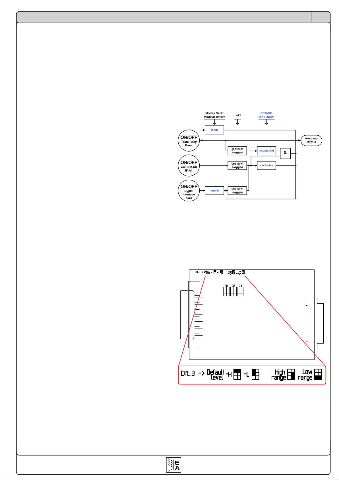
Die Grafik verdeutlicht die Verkettung der diversen
Zustände bzw. Bedingungen für Lokal-, Remote- und
Extern-Betrieb in Bezug auf das Ein/Ausschalten des
Leistungsausganges:
Grundeinstellung: LOW
DI2/Rem-SB
Sie können hiermit den Netzgeräteausgang ein- oder
ausschalten, blockieren oder freigeben. Abhängig von der
Einstellung Set output kann durch den Eingang DI2/Rem-
SB bestimmt werden, ob der Ausgang abhängig von einer
Freigabe durch die ON/OFF-Taste oder exklusiv im „Extern-Betrieb“ (analoge Schnittstelle) bzw. „Remote-Betrieb“
(digitale Schnittstellen) ein- und ausgeschaltet werden kann.
Die Freigabe wird in der Anzeige mit auto ON (Einschalt-
bereitschaft) signalisiert. Bei exklusiver On/Off-Funktion wird
der Leistungsausgang direkt über den Eingang DI2/REMSB geschaltet. Vorsicht ist geboten, da dies nicht durch die
ON/OFF-Taste an der Front bzw. ein Befehl über eine digitale
Schnittstellebeeinußtwerdenkann(Ausnahme:Gerätist
im „Lokal-Betrieb“, dann ist der Eingang wirkungslos).
DI2/Rem-SB
Set output Grundeinstellung: enable ON
= enable ON Die Freigabe der Einschaltbereitschaft
muß mit der ON/OFF-Taste erfolgen.
= exclusive Der Netzgeräteausgang kann nur
mit dem Eingang DI2/Rem-SB (oder
mit einer digitalen Schnittstelle, falls
bestückt) ein- bzw. ausgeschaltet werden.
Bei Verwendung der Einstellung enable ON muß der Ausgang wenigstens einmal freigegeben werden. Durch die
Einstellung Power ON = restore (sieheKongurationsmenü
des Gerätes) wird der Leistungsausgang nach Netzausfall
wieder freigegeben, sofern er es vor dem Netzausfall auch
war. Er kann danach ein-/ausgeschaltet werden.
Hinweis: der Netzgeräteausgang kann immer (Ausnahme:
expliziter Lokal-Betrieb), also auch bei nicht aktiver externer
Steuerung, mit DI2/Rem-SB abgeschaltet werden.
Kodierung der Eingänge DI1-3
Stecken Sie die Kurzschlußbrücken so wie in der Grafik
gezeigt, um den Eingangsspannungsbereich (siehe auch
„2. Technische Daten“) sowie den logischen Level des Einganges im nicht beschalteten Zustand festzulegen. Letzteres ist zu beachten, auch wenn die Eingänge nicht genutzt
werden, denn hiermit wird das Verhalten der Eingänge
DI1/SEL_enable und DI2/Rem-SB beeinflußt.
Default level legt den logischen Level des Einganges im
nicht beschalteten Zustand fest.
High range wählt den hohen Eingangsspannungsbereich
für den jeweiligen Eingang, bei dem „High“ einer Spannung
>9V und „Low“ einer Spannung <5V entspricht.
Low range wählt den niedrigen Eingangsspannungsbereich
für den jeweiligen Eingang, bei dem „High“ einer Spannung
>4V und „Low“ einer Spannung <1V entspricht.
© 2008, Elektro-Automatik GmbH & Co. KG
Irrtümer und Änderungen vorbehalten
12
Über die Schnittstellenkarten
DE
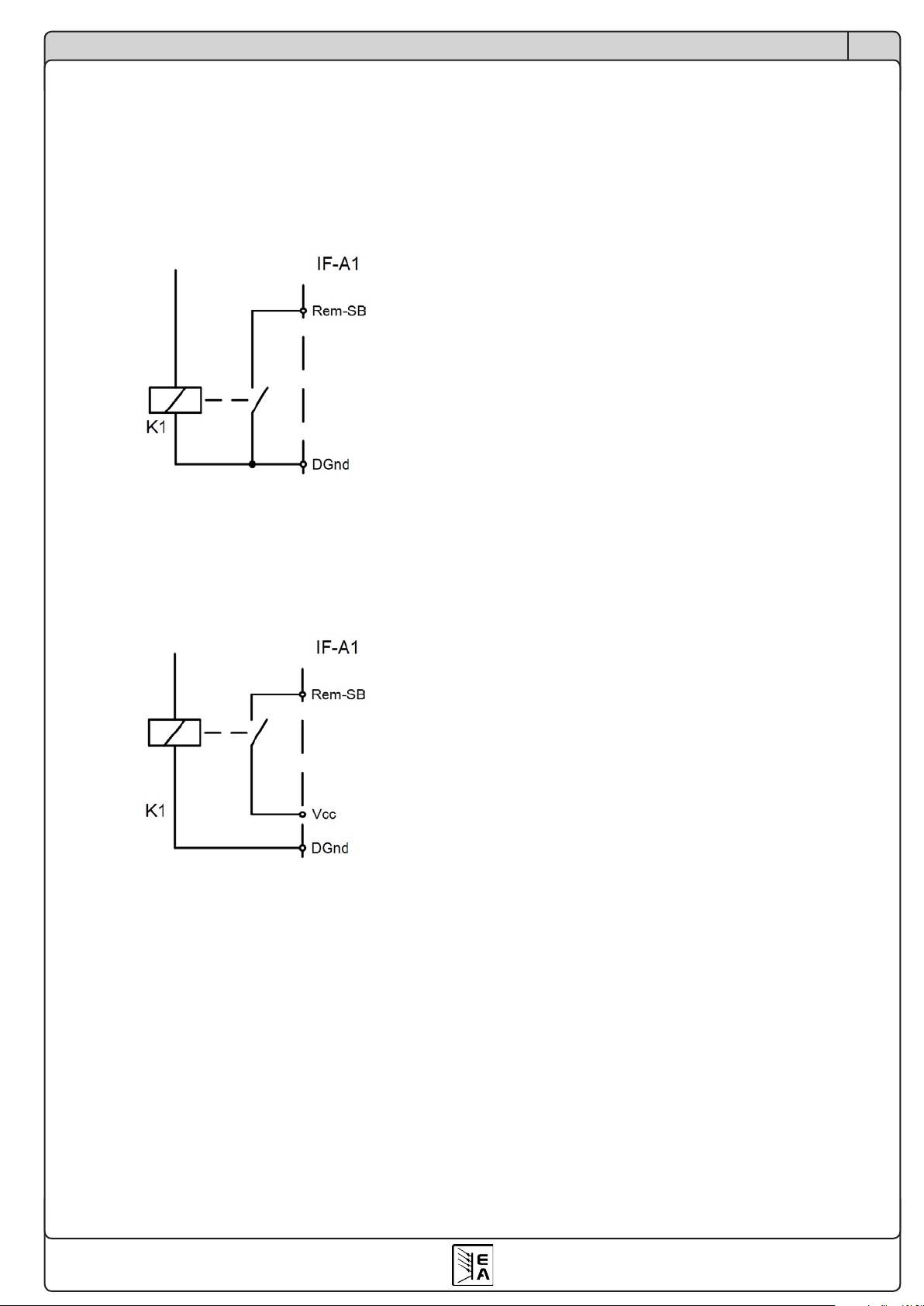
Beispiele: der Eingang DI2/Rem-SB, der das Gerät in den
Standby-Modus schaltet (Ausgang aus), kann mit Low oder
High am Eingang DI2 aktiviert werden, jenachdem, was in
der Konfiguration ausgewählt wurde.
Möglichkeit 1: der Eingang soll mit einem Relais nach GND
gezogen werden und den Geräteausgang dadurch ausschalten. Man muß also die Kodierung von DI2 auf „Default level
= H“ stecken und die Einstellung Standby = LOW, sowie Set
output = enable ON setzen.
Möglichkeit 2: der Geräteausgang soll durch eine Not-AusSchaltung abgeschaltet werden (Drahtbruchprinzip). Hierzu
muß die Kodierung von DI2 auf „Default level = L“ gesteckt,
die Einstellung im Menü auf Standby = LOW gesetzt werden.
Als Not-Aus-Schaltung dient für dieses Beispiel ein Relais
mit Schließerkontakt nach Vcc.
DO4/Mains OK Grundeinstellung: LOW
= { LOW | HIGH }
Wenn LOW gewählt wurde, wird der Ausgang gegen GND
geschaltet, solange Netzspannung vorhanden ist. Bei HIGH
wird er gegen 12...15V gezogen.
DO5/Standby Grundeinstellung: LOW
= { LOW | HIGH }
Wenn LOW gewählt wurde, wird der Ausgang gegen GND
geschaltet, sobald der Leistungsausgang ausgeschaltet wird
(Standby). Bei HIGH wird er gegen 12...15V gezogen.
DO6/CC Grundeinstellung: LOW
= { LOW | HIGH }
Wenn LOW gewählt wurde, wird der Ausgang gegen GND
geschaltet, sobald die Regelung des Netzteils über den
Sollwert des Stromes bestimmt wird (CC-Betrieb). Bei HIGH
wird er gegen 12...15V gezogen.
Digitale Ausgänge mit freier Funktionsbelegung
Die digitalen Ausgänge DO2, DO3 und DO7 können in ihrer
Funktionsbelegung wahlweise konguriert und die Logik
kann invertiert werden.
DO2 Grundeinstellung: OVP LOW
DO3 Grundeinstellung: OT LOW
DO7 Grundeinstellung: CP LOW
Es gibt natürlich noch weitere Alternativen.
Digitale Ausgänge mit fester Funktionsbelegung
Die digitalen Ausgänge DO1, DO4, DO5 und DO6 können in
ihrer Funktionsbelegung nicht geändert werden. Sie können
aber den ausgegebenen Logikpegel invertieren.
DO1/CV Grundeinstellung: LOW
= { LOW | HIGH }
Wenn LOW gewählt wurde, wird der Ausgang gegen GND
geschaltet, sobald die Regelung des Netzteils über den Sollwert der Spannung bestimmt wird (CV-Betrieb). Bei HIGH
wird er gegen 12...15V gezogen.
Jedem der Ausgänge kann eine der folgenden Funktionen
zugewiesen werden:
= remote Das Netzgerät wird über eine digitale Schnitt-
stelle ferngesteuert.
= OT Übertemperatur wird gemeldet.
= CP Das Netzgerät wird über den Sollwert
der Leistung geregelt (CP-Betrieb).
= Alarm Bei einem Alarm wird das Netzteil automatisch
abgeschaltet und dies kann über einen
digitalen Ausgang ausgegeben werden.
= trip U Auslösung durch Überschreiten der Grenzen
U> und/oder U< (siehe Handbuch PSI9000).
= trip I Auslösung durch Überschreiten der Grenzen
I> und/oder I< (siehe Handbuch PSI9000).
= trip U+I Auslösung durch Überschreiten der Grenzen
U>, U<, I> und/oder I<(siehe Handbuch
PSI9000).
Festlegen des Logikpegels bei Auslösung:
= LOW Der Ausgang wird gegen GND gezogen,
sobald die ausgewählte Funktion aktiv wird.
= HIGH Der Ausgang wird über einen hochohmigen
Widerstand gegen +15V gezogen, sobald die
ausgewählte Funktion aktiv ist.
© 2008, Elektro-Automatik GmbH & Co. KG
Irrtümer und Änderungen vorbehalten
13
, , ,
, ,
0,2
Anfrage ü GPIB P ü MC v MC
Antwort ü MC P ü GPIB
T T T T T
T T T T
= + + +
= + + • +
M
Über die Schnittstellenkarten
DE
4.5 GPIB-Karte IF-G1
Die Schnittstellenkarte IF-G1 bietet eine nach IEEE 488.1/2
standardisierte, digitale Schnittstelle (GPIB). Die Installation
der Karte ist in der der Packung beiliegenden Kurzinstallationsanleitung beschrieben.
Falls in einem Gerät der Serie PSI 9000 eine weitere Schnittstellenkarte genutzt werden soll, so ist die IF-G1 mit der
analogen Schnittstellenkarte IF-A1 oder den digitalen Karten
IF-R1 bzw. IF-U1 kombinierbar. Die CAN-Karte IF-C1 darf
nicht zusammen mit der IF-G1 betrieben werden!
4.5.1 Hinweise zur Kommunikation
Die Karte arbeitet nicht mit dem objektorientierten Kommunikationsprotokoll, sondern mit dem international standardisierten SCPI-Befehlssatz, der textbasiert ist. Das heißt,
es wird Klartext im ASCII-Format übertragen, was die Programmierung erleichtert.
4.5.2 Ansteuerung des Gerätes über GPIB
Prinzipiell gilt hier die gleiche Vorgehensweise wie bei den
anderen digitalen Schnittstellenkarten. Wenn das Gerät über
die Karte mit einem PC verbunden und vor der ersten Verwendung konfiguriert wurde, können mit den entsprechenden
Befehlen jederzeit der Status sowie Istwerte abgefragt werden. Eine Steuerung des Gerätes (Ein/Aus, Sollwerte setzen
usw.) erfordert die Umschaltung in den Fernsteuerbetrieb,
was nicht automatisch geschieht. Die benötigten Befehle
dazu sind weiter unten beschrieben.
Hinweis: mit GPIB können maximal nur 15 Geräte gleichzeitig verbunden werden!
4.5.5 Ausführungs- und Übertragungszeiten
Die Zeit zur Protokollumsetzung und die Verarbeitungszeit
des geräteinternen Mikrocontrollers sind abhängig vom Befehl und sind der Übertragungszeit hinzuzufügen. Typisch
liegen die Zeiten bei:
Zeit zur Protokollumsetzung Tp: 2ms
Übertragungszeit zum geräteinternen
Mikrocontroller T
: 0,5ms
ü,mc
Verarbeitungszeit des geräteinternen
Mikrocontrollers T
v,mc
: 2ms
Erwartet der Hostrechner eine Antwort vom Gerät, kann
sich, abhängig vom Befehl, eine Gesamtzeit von bis zu
ergeben.
Die Übertragungszeit T
des GPIB ist sehr kurz. Sie liegt
ü,GPIB
typisch bei 0,2ms. Es wird aber eine Befehlsintervallzeit
>30ms empfohlen. Kleinere Zeiten können zu Kommunikationsfehlern führen.
4.5.6 IF-G1kongurieren
Die Schnittstelle wird über das Setup-Menü konfiguriert.
Es ist zwingend erforderlich die Geräteadresse „device node“
einzustellen. Das Gerät kann nur so eindeutig im System
identifiziert werden. Über diesen Identifier wird das Gerät
angesprochen. Jedes Gerät muß eine andere Geräteadresse
bekommen, wenn mehrere gleichzeitig vom einem Steuergerät gesteuert werden. Zugriff auf das Setup-Menü:
4.5.2 Begriffserläuterung
GPIB General Purpose Interface Bus
IEEE60488.1 genormte GPIB Schnittstelle zum Host
rechner (ältere Bezeichnungen IEC-Bus,
IEC 625 Bus , ANSI Standard MC1.1)
SCPI Standard Commands for Programmable
Instruments => Standardisierte Kommandosprache zur Kommunikation mit Instrumenten, Messgeräte etc.
4.5.4 Unterschiede zu den anderen Schnittstellenkarten
Für die Kommunikationsverbindung zum Hostrechner (PC,
SPS o.ä.) wird eine GPIB-Schnittstelle benutzt. Für diese
wird die standardisierte Kommandosprache SCPI mit ihren
textbasierenden Befehlen verwendet. Das Protokoll unterscheidet sich erheblich von den anderen digitalen Schnittstellenkarten IF-xx. Diese nutzen ein objektorientiertes,
nicht standardisiertes, bei allen anderen Schnittstellenkarten
einheitliches Kommunikationsprotokoll.
+ Communication +
-
device node Grundeinstellung: 1
= {1..15} Es kann eine von 15 Geräteadressen1)
vergeben werden.
Slot A : { IF-… } abhängig von der Einsteckkarte
Slot B : { IF-… } abhängig von der Einsteckkarte
Sie stellen hier die erforderliche Geräteadresse ein und
erhalten eine Übersicht über die bestückten Karte(n). Soll-
ten Sie diese Einstellung ändern, ohne das Gerät neu
einzuschalten, muß der Befehl *RST gesendet werden,
um die Einstellungen zu übernehmen.
Achtung! Bei der Geräteserie PSI9000 bis Firmwareversion
3.04 bzw. bei den Geräteserien EL3000/9000 bis Firmwareversion 2.11 wird die Schnittstellenkarte als „IF-C1“, also
wie eine CAN-Karte, angezeigt. Sie muß auf 100kBd, kein
Busabschluß und RID = 0 eingestellt werden. Ab Firmwareversion 3.05 (PSI) bzw. 2.12 (EL) wird die Karte richtig als
IF-G1 erkannt.
4.5.7 Zubehör
Das der Karte beiliegende Kabel dient zum späteren Update
der Mikroprozessorfirmware mit einem Updatetool.
1) Auch wenn am Gerät eine Adresse bis 30 eingestellt werden kann, werden nur Adressen 1 bis 15 für GPIB unterstützt. Ab device node 16 beginnt die Zuweisung von 0 an
erneut, wodurch device node 16 nicht zulässig ist.
© 2008, Elektro-Automatik GmbH & Co. KG
Irrtümer und Änderungen vorbehalten
14

Über die Schnittstellenkarten
DE
4.5.8 SCPI-Befehle
Die SCPI-Befehle werden als Klartext gesendet. Es ist ein
Steuerzeichen zu benutzen, das das Ende der Übertragung
kennzeichnet: LF (Line Feed, 0xA, ASCII 10).
Die IF-G1 beachtet folgendes Zeichen nicht:
CR = ASCII Code 13 (0xD), falls es am Ende einer Befehls-
zeile vor dem Zeichen LF (Line feed) steht. Falls CR nach
LF kommt, entsteht ein Fehler für den nächsten Befehl.
Eine Übertragung erfordert zuerst eine Mitteilung vom Host
(PC/SPS etc). Diese muss mit LF abgeschlossen werden.
Die IF-G1 antwortet, wenn der Host eine Antwort erwartet.
Das ist immer dann der Fall, wenn am Ende des Befehls
ein „?“ steht.
Befehle, die etwas stellen/setzen sollen, bestehen immer
aus dem Befehl selbst und einem oder mehreren Werten.
Der Befehl kommt zuerst, der oder die Werte durch Kommas
getrennt danach:
<BEFEHL><Numeric value>,<Numeric value>...
Generell können Befehle in ihrer Kurz- oder Langform ge-
sendet werden. Nachfolgend wird die Kurzform der Befehle
in großgeschriebenen Buchstaben angegeben und ist stets
ein Teil der Langform.
Syntaxformat
Spezifikation nach „1999 SCPI Command reference”.
Folgende Syntaxformate können in Befehlen bzw. Antworten
auftreten:
<Numeric value>
Der Zahlenwert entspricht dem Zahlenformat
im Display des Gerätes und ist abhängig von
den Nennwerten des Gerätes. Es gilt:
- er wird vom voranstehenden Befehl immer
mit einem Leerzeichen getrennt eingeben
- Anstatt eines Zahlenwertes können alternativ:
MIN (entspricht dem Minimalwert des
Parameters )
oder
MAX (entspricht dem Maximalwert des
Parameters
übertragen werden.
Achtung! Sollwerte, die höher sind als die
Nennwerte des Gerätes, erzeugen einen
Fehler!
<NR1> Zahlenformat ohne Dezimalpunkt
<NR2> Zahlenformat mit Dezimalpunkt
<NR3> Zahlenformat mit Dezimalpunkt und Exponent
<NRf> enthält<NR1>,<NR2>,<NR3>
<NRf+> enthält<NR1>, <NR2>, <NR3> sowie MIN und MAX
Unit V Volt
A Ampere
W Watt
OHM Ohm
s Sekunden
<CHAR> 0..255: Dezimalzahl (Ausgabe)
#B0000 0000 … #B1111 1111: Binärdarstellung
#H00… #HFF: Hexadezimaldarstellung
<+INT> 0..32768: positive Integerzahl (Ausgabe)
#B0000 0000 0000 0000… #B0111 1111 1111 1111:
Binärdarstellung
#H0000… #HFFFF: Hexadezimaldarstellung
<B0> 1 oder ON: Funktion wird eingeschaltet
0 oder OFF: Funktion wird ausgeschaltet
<B1> NONE: lokaler Betrieb, eine Umschaltung auf
Fernbedienung ist möglich
LOCal: nur lokaler Betrieb möglich, Auslesen
von Daten ist zulässig
REMote: Fernbedienung des Gerätes ist akti
viert
<B2> ON oder 1: Automatische Messwerterfassung
mit x Messpunkten
ONCE oder 0: einmalige Messwerterfassung
ausgelöst über *TRG mit x Messpunkten
<ERR> Error und Eventnummer (-800 bis 399)
<SRD> String
<LF> Endezeichen (line feed, 0x0A)
<Time> [[ddd], [hh], [mm], [s]s.s[s][s][s][s][s][s]
Standardformat ist Sekunden (s.s)
; Das Semikolon wird verwendet, um innerhalb
einer Message mehrere Befehle zu senden.
: Der Doppelpunkt trennt höherwertige Schlüssel
wörter von niederwertigeren Schlüsselwörtern
[ ] Kleinbuchstaben und der Inhalt in rechteckigen
Klammern sind optional.
? Das Fragezeichen kennzeichnet eine Abfrage.
Die Abfrage kann gleichzeitig mit einer Daten-
sendung verknüpft werden. Hierbei ist darauf
zu achten daß, bevor eine neue Datensendung
erfolgt, die Antwort des Systems abgewartet
werden muss.
-> Anwort vom Gerät
GerätespezischeBefehleundParameter
Rot: gilt nur für PSI-Netzgeräte
Blau: gilt nur für elektronische Lasten
Schwarz: gilt für alle Geräte
Allgemeine IEEE488.2 Befehle
*IDN? Liest die Geräteidentifikation aus. Antwort:
Benutzerdef. Text , Hersteller, Gerätetyp,
Geräteserienummer, Gerätefirmwareversion
und Firmwareversion der Schnittstellenkarte
<LF>
*RST Gerät zurücksetzen durch folgende Prozedur:
- Umschaltung in Remote-Betrieb
- den Ausgang/Eingang auf AUS setzen
- alle Fehlermeldungen des Gerätes zurücksetzen
- Sollwerte setzen:
Usoll = 0, Isoll=0, Psoll=MAX, Rsoll= MIN
*TRG Triggert einen Messzyklus
*CLS Löscht alle Event- und Statusregister des GPIB
Controllers
*ESE <CHAR> Setzt das Event Status Enable Register
-
-
© 2008, Elektro-Automatik GmbH & Co. KG
Irrtümer und Änderungen vorbehalten
15
Über die Schnittstellenkarten
OPC = OPeration Complete bit
EXE= EXecution Error
QYE= QuerY Error
CME= CoMmand Error
DDE= Device Depend Error
Reduce Power
Questionable Status
QUES
CV
CC
CR
LOCAL
Fct. running
EXTERNAL
Input / Output on
err
oper
U = User defined
Event
OR
Operation Status
OPER
ques
data
data
data
data
OUTPUT Buffer
mav
Service
Request
Enable
SRE
STATUS
STB
0 0
0 0
1 1
1 1
0 0
1 1
1
1 1
0
1
7
6
5
4
3
2
OR
mss
rsv
Service Request
Generation
Condition
z
0
0
z
z
z
0
z
0
1
7
6
5
4
3
2
Standard Event Status
Register
ESE ESR
Power on
OPC
EXE
CME
DDE
OR
esr
CP
Output Enable
Error
Error
0
Error Queue
<>0
Function mode
REMOTE
Fct. at start
Fct. stepping
z = State of the indicated information
D = Set after power On
0
0
0
0
0
0
0
0
0
0
0
0
0
0
0
0/z
0/z
0/z
0/z
0/z
0/z
0/z
0
z
z
z
0
0/z
0
0
0
1
7
6
5
4
3
2
8
9
10
11
12
13
14
0
0
0
0
0
0
0
0
0
0
0
0
0/1
0
0
0/1
0/1
0/1
0/1
0/1
0/1
0/1
0
1
1
1
0
0/1
0
0
0/D
0/D
0/D
0/D
0/D
0/D
0/D
0
D
D
D
0
0/U
0
0
Enable
Condition
Positive transition
Negative transition
Event
OR
0
0
0
0
0
0
0
0
0
0
0
0
0
0
0
z
z
z
z
z
z
z
z
0
0
0
z
z
0
0
0
1
7
6
5
4
3
2
8
9
10
11
12
13
14
0
0
0
0
1
0
0
0
0
0
0
1
0/1
0
0
1
1
1
1
0/1
0/1
0/1
0/1
0
0
0
1
0/1
0
0
D
D
D
D
0/U
0/U
0/U
0/U
0
0
0
D
0/U
0
0
Enable
Condition
Positive transition
Negative transition
Enable
1
0
0
1
1
1
0
1
Event
0
0
0
0
0
0
0
0
MODE_A
MODE_B
MODE_AB
MODE_BAT
MODE_CR1
MODE_CR2
MODE_CV
DE
*ESE? Liest das Event Status Enable Register
*ESR? Liest das Event Status Register, das nach dem
Lesen gelöscht wird
*SRE <CHAR> Setzt das Service Request Enable Register
*SRE? Liest das Service Request Enable Register
*STB? Liest das Status Byte Register, das nach dem
Lesen gelöscht wird
Service Request (SRQ) / Bedienungsruf-Generierung
Der GPIB-Controller übernimmt automatisch die Abwicklung,
die über das Bit rsv im Statusregister STB ausgelöst wird.
Nach der Generierung und anschließender Abfrage mit
*STB? vom Host aus wird das Register gelöscht.
Der Signallauf wird im Diagramm unten verdeutlicht.
Ein SRQ (Bedienrufsignal) wird erzeugt, wenn das Bit rsv im
STATUS Register (STB) gesetzt und die zugehörigen Bits für
die Ereignisse, die ein SRQ auslösen können, im ServiceRequest-Enable Register (SRE) aktiviert sind.
Welche Ereignisse einen Bedienruf auslösen können, wird
mit dem Service Request Enable Register durch den Befehl
*SRE <CHAR> festgelegt.
Die Bits des Statusregisters STB im Einzelnen:
Bit 0: nicht verwendet
Bit 1: nicht verwendet
Bit 2:
err, Error Queue (Fehlerliste) ist gefüllt; durch Aus-
lesen der Fehlerliste wird diese gelöscht und das
Bit zurückgesetzt. Die Liste kann bis zu 4 Fehler
speichern
Bit 3: ques, Questionable Status Register ist aktiv (ein oder
mehrere Ereignisse stehen an)
Bit 4: nicht verwendet
Bit 5: esr, das Standard Event Status Register (ESR), mas-
kiert mit dem Event Status Enable Register (ESE),
meldet, daß ein oder mehrere Ereignisse anstehen
Bit 6: rsv, immer aktiv
Bit 7: oper, meldet, daß im Operation Status Register ein
oder mehrere Ereignisse anstehen
Die Ereignisbits der verschiedenen Register werden zum
STB gemeldet, wenn Ereignisse aufgetreten sind, die durch
die zugehörigen Bits in den Freigabe-Registern (*ESE, *SRE
bzw. STAT:QUES:ENAB, STAT:OPER:ENAB) zugelassen
wurden.
Die Eingangsbits der Register sind, wie im Diagramm zu
sehen, zugeordnet. Rot bedeutet, diese Signale sind nur bei
PSI 9000 Geräten verfügbar, blau nur für EL3000/9000.
© 2008, Elektro-Automatik GmbH & Co. KG
Irrtümer und Änderungen vorbehalten
Legende:
CC/CV/CP/CR = aktuelle Regelungsart
Reduce Power = Leistungsbegrenzung
Fct. at start/running/stepping = Funktionsmanagerstatus
Input / Output on = Eingang bzw. Ausgang des Gerätes ist eingeschaltet
Output enable = Einschaltbereitschaft des Ausganges ist aktiviert
MODE_A/B/AB/BAT = aktuelle Betriebsart, gewählt am Drehschalter
MODE_CR1/CR2 = aktueller Widerstandsbereich (CR1 ist der kleinere)
LOCAL = Gerät im Lokalbetrieb, Fernsteuerung ist gesperrt
REMOTE = Gerät wird durch digitale Schnittstellenkarte gesteuert
EXTERNAL = Gerät wird durch analoge Schnittstellenkarte bzw. Analogschnittstelle am Gerät gesteuert
Function mode = Funktionsmanager aktiv
16

Über die Schnittstellenkarten
Die Bits des ESR sind im Einzelnen:
Bit 0: Operation complete, bezieht sich auf die Mittelwertbildung (siehe weiter unten), gesetzt wenn erfolgreich beendet
Bit 1: nicht verwendet
Bit 2: nicht verwendet
Bit 3: Device Dependent Error (Hardware defekt etc.); Fehler von -399 bis -300 bzw. 100...399
Bit 4: Execution Error (Strombegrenzung, Grenzwerte überschritten); Fehler von -299 bis -200
Bit 5: Command Error (falscher Befehl); Fehler von -199 bis -100
Bit 6: nicht verwendet
Bit 7 Power On (Gerät wurde eingeschaltet)
Ereignis- und Statusregister können mit dem Befehl *CLS gelöscht werden.
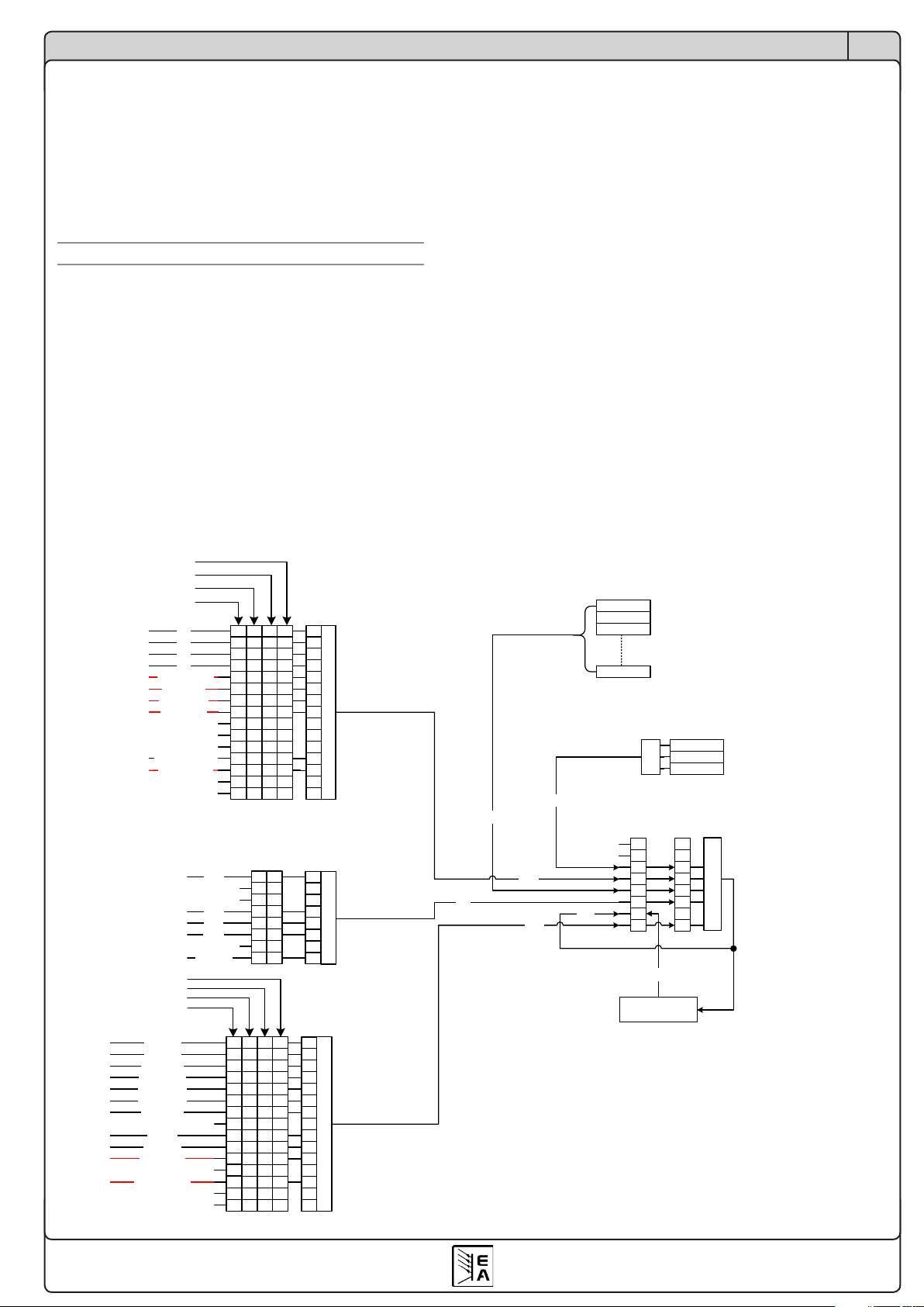
Statusbefehle
Das Operation Status Register (OPER) (siehe Grafik auf der vorherigen Seite) speichert das Auftreten von Zuständen
(remote, local usw. ) im Register Condition zwischen und gibt diese weiter an das Register Event, sofern diese durch
Enable freigegeben sind. Die Masken Positive transition und Negative transition bestimmen, ob die Ereignisse bei einer
Low-High-Flanke oder einer High-Low-Flanke ausgegeben werden. Somit kann zum Einen das Auftreten und zum Anderen
das Verschwinden eines Zustandes bemerkt werden.
Das gleiche Prinzip gilt für das Questionable Status Register (QUES). In der im Bild gezeigten Konfiguration für das OPER
würde das Signal „local“ nur bei einer pos. Flanke (Low->High) ein Ereignis ausgeben, das Signal „Function mode“ dagegen
auch bei einer neg. Flanke.
STATus
OPERation Betriebsabhängige Meldungen
:
:
:
:ENABle <+INT> Freigabe des Ereignisses(Event)
:
:
:
:
:
:
:
:
:
:
:
:
:
:
EVENT? -><+INT> Abfrage der Ereignisse im Status Operation Register
CONDition? -><+INT> Zustand der betriebsabhängigen Funktionen abfragen
ENABle? -><+INT> Abfrage
PTRtransition <+INT> Event, nur bei Übergang von 0 auf 1
PTRtransition? -><+INT> Abfrage
NTRtransition <+INT> Event, nur bei Übergang von 1 auf 0
NTRtransition? -><+INT> Abfrage
QUEStionable GeräteundfunktionsspezischeEreignisse
EVENT? -><+INT> Abfrage der Ereignisse im Questionable Status Register
CONDition? -><+INT> ZustandderGerätespezischenFunktionenabfragen
ENABle <+INT> Freigabe des Ereignisses(Event)
ENABle? -><+INT> Abfrage
PTRtransition <+INT> Event, nur bei Übergang von 0 auf 1
PTRtransition? -><+INT> Abfrage
NTRtransition <+INT> Event, nur bei Übergang von 1 auf 0
NTRtransition? -><+INT> Abfrage
DE
Beispiele:
STAT:OPER? Abfrage des OPERation Status Event Register
STAT:QUES? Abfrage des QUEStionable Status Event Register
STAT:OPER:ENAB255 Setzt alle Ereignisbits für das OPERation Status Event Register
Systembefehle
(Spezifikation nach „1999 SCPI Command reference“:19 System Subsystem)
[SYSTem:]
ERRor:ALL? -><Err>[,<Err>]… Abfrage des Fehlerbuffers, Fehlermeldungen aus Fehlerliste lesen,
die Bits
ERRor:NEXT? -><Err> Abfrage letzter Fehler, wenn die Fehlerliste leer wird, werden die Bits
err, esr sowie ESR:Condition gelöscht
© 2008, Elektro-Automatik GmbH & Co. KG
Irrtümer und Änderungen vorbehalten
err, esr sowie ESR:Condition werden gelöscht.
17

Über die Schnittstellenkarten
[SYSTem:]
LOCK
[:STATE] <B0> 1= Setzt das Gerät in Fernsteuerbetrieb, falls SYST:LOCK:OWN? mit
„NONE“ beantwortet wird.
0= verlässt den Remotebetrieb
Hinweis: die Geräte können, ohne daß sie in den Fernsteuerbetrieb versetzt wurden, nur überwacht werden. Das
bedeutet, man kann nur Istwerte und Zustände abfragen. Um Zustände und Sollwerte zu setzen, müssen sie vorher
mit LOCK:STATE 1 bzw. *RST (siehe 2.2) in den Fernsteuerbetrieb gesetzt werden. Um dies zu können, darf der
Fernsteuerbetrieb nicht gesperrt sein. Über die Bedingungen für Freigabe/Sperre des Fernsteuerbetriebes lesen Sie bitte
im Handbuch des Gerätes nach. Die Freigabe kann über den folgenden Befehl abgefragt werden.
[SYSTem:]
LOCK
:OWNer? -><B1> Abfrage des Bedienortes
NONE: Das Gerät kann in den Fernsteuerbetrieb geschaltet werden
(Bit 8,9,10 =0 in OPER Condition)
LOCal: Das Gerät ist lokal und für den Fernsteuerbetrieb gesperrt
(Bit 8=1,9=0,10=0 in OPER Condition )
Externbetrieb wird als LOCal gedeutet.
(Bit 8=0,9=0,10=1 in OPER Condition)
REMote: Das Gerät ist in Remote via IF-G1
(Bit 8=0,9=1,10=0 in OPER Register)
VERSion? -><SRD> Abfrage SCPI-Version
DE
Beispiele:
SYST:LOCK:OWN? Fragt den Bedienort ab
SYST:LOCK:STATE1 Setzt das Gerät in den zur Steuerung erforderlichen Fernsteuerbetrieb
SYST:LOCKON dito
Befehle zur Steuerung des Ausgangs/Eingangs
Leistungseingang bzw. -ausgang aktivieren/deaktivieren. Dabei ist die Zuordnung von OUTP bzw. INP zum Gerätetyp
gegeben. D.h., ein Netzgerät hat einen Ausgang und kann hier nur mit OUTP angesprochen werden. Auf INP wird beim
Netzgerät nicht reagiert. Bei der elektronischen Last ist es dementsprechend umgekehrt.
OUTPut[:STATe]? -><B0> Abfrage Zustand des Leistungsausgangs
OUTPut[:STATe] <B0> Schaltet den Leistungsausgang ein oder aus
INPut[:STATe]? ->B0 Abfrage Zustand des Leistungseingangs
INPut[:STATe] <B0> Schaltet den Leistungseingang ein oder aus
Beispiele:
OUTPON Schaltet den Leistungsausgang ein, setzt aber nicht die Alarme und Warnungen zurück oder
quittiert sie. D.h., steht ein Alarm an, kann der Befehl nicht ausgeführt werden.
INP1 Dito, aber für den Eingang (einer elektronischen Last)
© 2008, Elektro-Automatik GmbH & Co. KG
Irrtümer und Änderungen vorbehalten
18

Über die Schnittstellenkarten
Meßbefehle
Anfrage der aktuellen Istwerte. Bei der Meßwerterfassung müssen die Einstellungen für die Mittelwertbildung beachtet
werden Siehe Abschnitt „Mittelwertbildung“ weiter unten.
MEASure
[:SCALar]
:VOLTage[:DC]? -><NRf>Unit Abfrage: Spannungsistwert
:CURRent[:DC]? -><NRf>Unit Abfrage: Stromistwert
:POWer[:DC]? -><NRf>Unit Abfrage: Leistungsistwert
[:ARRay]? -><NRf>Unit, <NRf>Unit … Abfrage: Spannungistwert, Stromistwert, Leistungsistwert...
Beispiele:
MEAS:CURR? Mißt und liefert den aktuellen Strom bzw. dessen Mittelwert.
MEAS:ARR? Gibt eine geräteabhängige Anzahl von Istwerten zurück. Bei PSI/EL sind dies: U, I, P
Sollwertbefehle
Durch Anhängen eines Fragezeichens können alle Sollwerte auch ausgelesen werden. Für die Bedeutung von Level A, B
und A/B bei den elektronischen Lasten bitte auch das Handbuch des Gerätes lesen!
DE
I. Spannungssollwert / Überspannungsgrenze
(Spezifikation nach „1999 SCPI Command reference“:19 Source Subsystem)
Für elektronische Lasten gilt:
• Befehle, die speziell für elektronische Lasten sind, werden ab der Firmware 3.01 oder höher unterstützt
• der HIGH-Sollwert muß immer größer als der LOW-Sollwert sein, ansonsten wird ein Fehler zurückgegeben.
• Abfragen und Setzen von Sollwerten bezieht sich stets auf die gesetzte „Level Control“ und den vorgewählten „Mode“.
D.h., wenn Level A aktiv ist, wird mit VOLT der Spannungssollwert für Level A gesetzt usw., wenn auch Mode CV aktiv ist.
Ansonsten wird der Sollwert nicht angenommen. Die Befehle HIGH und LOW gelten nur für Level A/B-Betrieb und erzeugen in anderen Modi Fehler. Der jeweilige Modus ist vor dem Wechsel in den Remotebetrieb zu setzen. Die anderen, nicht
zum vorgewählten Modus gehörenden Sollwerte können dann nicht mehr geändert werden und sind vorher festzulegen.
Es wird daher empfohlen, für dauerhafte Fernsteuerung des Gerätes die Option „Keep set values“ im Setupmenü auf „no“
zu stellen, damit die Sollwerte beim Umschalten des „Mode“ stets zurückgesetzt werden.
[SOURce:]
VOLTage
[:LEVel]? -><NRf>Unit Abfrage letzter Spannungssollwert
Level A oder B, jenachdem was gerade aktiv ist
[:LEVel] <NRf+>[Unit] Spannungssollwert setzen
Level A oder B, jenachdem was gerade aktiv ist
:HIGH <NRf+>[Unit] Spannungssollwert für Level A im Level A/B-Betrieb setzen
:HIGH? -><NRf>Unit Spannungssollwert für Level A im Level A/B-Betrieb abfragen
:LOW <NRf+>[Unit] Spannungssollwert für Level B im Level A/B-Betrieb setzen
:LOW? -><NRf>Unit Spannungssollwert für Level B im Level A/B-Betrieb abfragen
:PROTection[:LEVel] <NRf+>[Unit] OVP-Spannung setzen (nur wenn Ausgang aus)
:PROTection[:LEVel]? -><NRf>Unit Abfrage: OVP-Spannung
Beispiele:
VOLT5.05 Setzt 5,05V Ausgangsspannung am Netzgerät bzw. Spannungsgrenze an einer E-Last
VOLT6.91V Setzt 6,91V Spannung
VOLT?
SOUR:VOLT:PROT67 Setzt die Überspannungsgrenze (OVP) auf 67V (nur PSI 9000), wenn der Ausgang aus-
geschaltet ist. Ansonsten wird nichts übernommen und ein Fehler erzeugt.
© 2008, Elektro-Automatik GmbH & Co. KG
Irrtümer und Änderungen vorbehalten
Fragt den zuletzt gesetzten Spannungssollwert ab
19

Über die Schnittstellenkarten
II. Stromsollwert
(Spezifikation nach „1999 SCPI Command reference“:19 Source Subsystem)
Für elektronische Lasten gilt:
• Befehle, die speziell für elektronische Lasten sind, werden ab der Firmware 3.01 oder höher unterstützt
• der HIGH-Sollwert muß immer größer oder gleich als der LOW-Sollwert sein, ansonsten wird ein Fehler zurückgegeben.
• Abfragen und Setzen von Sollwerten bezieht sich stets auf die gesetzte „Level Control“. D.h., wenn Level A aktiv ist, wird
mit CURR der Stromsollwert für Level A gesetzt usw. Die Befehle HIGH und LOW gelten nur für Level A/B-Betrieb und
erzeugen in anderen Modi Fehler. Der jeweilige Modus ist vor dem Wechsel in den Remotebetrieb zu setzen. Die anderen,
nicht zum vorgewählten Modus gehörenden Sollwerte können dann nicht mehr geändert werden und sind vorher festzulegen. Es wird daher empfohlen, für dauerhafte Fernsteuerung des Gerätes die Option „Keep set values“ im Setupmenü auf
„no“ zu stellen, damit die Sollwerte beim Umschalten des „Mode“ stets zurückgesetzt werden.
[SOURce:]
CURRent
[:LEVel]? -><NRf>[Unit] Abfrage letzter Stromsollwert
Level A oder B, jenachdem was gerade aktiv ist
[:LEVel] <NRf+>Unit Stromsollwert setzen
Level A oder B, jenachdem was gerade aktiv ist
:HIGH <NRf+>[Unit] Stromsollwert für Level A im Level A/B-Betrieb setzen
:HIGH? -><NRf>Unit Stromsollwert für Level A im Level A/B-Betrieb abfragen
:LOW <NRf+>[Unit] Stromsollwert für Level B im Level A/B-Betrieb setzen
:LOW? -><NRf>Unit Stromsollwert für Level B im Level A/B-Betrieb abfragen
DE
Beispiele:
CURR20.00 Setzt 20A Eingangs- oder Ausgangsstrom, je nach Gerätetyp
CURR:HIGH? Fragt den Stromsollwert von Level A im Level A/B-Betrieb ab
SOUR:CURR:LOW0.4A Setzt den Stromsollwert Level B für Level A/B-Betrieb auf 0.4A
III. Leistungssollwert
(Spezifikation nach „1999 SCPI Command reference“:19 Source Subsystem)
Für elektronische Lasten gilt:
• Befehle, die speziell für elektronische Lasten sind, werden ab der Firmware 3.01 oder höher unterstützt
• der HIGH-Sollwert muß immer größer oder gleich als der LOW-Sollwert sein, ansonsten wird ein Fehler zurückgegeben.
• Abfragen und Setzen von Sollwerten bezieht sich stets auf die gesetzte „Level Control“. D.h., wenn Level A aktiv ist, wird
mit POW der Leistungssollwert für Level A gesetzt usw. Die Befehle HIGH und LOW gelten nur für Level A/B-Betrieb und
erzeugen in anderen Modi Fehlermeldungen. Der jeweilige Modus ist vor dem Wechsel in den Remotebetrieb zu setzen.
Die anderen, nicht zum vorgewählten Modus gehörenden Sollwerte können dann nicht mehr geändert werden und sind
vorher festzulegen. Es wird daher empfohlen, für dauerhafte Fernsteuerung des Gerätes die Option „Keep set values“ im
Setupmenü auf „no“ zu stellen, damit die Sollwerte beim Umschalten des „Mode“ stets zurückgesetzt werden.
[SOURce:]
POWer
[:LEVel]? -><NRf>Unit Abfrage letzter Leistungssollwert
Level A oder B, jenachdem was gerade aktiv ist
[:LEVel] <NRf+>[Unit] Leistungssollwert setzen
Level A oder B, jenachdem was gerade aktiv ist
:HIGH <NRf+>[Unit] Leistungssollwert für Level A im Level A/B-Betrieb setzen
:HIGH? -><NRf>Unit Leistungssollwert für Level A im Level A/B-Betrieb abfragen
:LOW <NRf+>[Unit] Leistungssollwert für Level B im Level A/B-Betrieb setzen
:LOW? -><NRf>Unit Leistungssollwert für Level B im Level A/B-Betrieb abfragen
© 2008, Elektro-Automatik GmbH & Co. KG
Irrtümer und Änderungen vorbehalten
20

Über die Schnittstellenkarten
Beispiele:
POW:LEV2300 Setzt das Gerät auf 2300W Leistungsbegrenzung, sofern dieser Wert zulässig ist
POW:LOWMIN Setzt den Leistungssollwert für Level B im Level A/B-Betrieb auf 0W
IV. Innenwiderstandssollwert
(Spezifikation nach „1999 SCPI Command reference“:19 Source Subsystem)
Für elektronische Lasten gilt:
• Subsysteme, die speziell für elektronische Lasten sind, werden ab der Firmware 3.01 oder höher unterstützt
• der HIGH-Sollwert muß immer größer oder gleich als der LOW-Sollwert sein, ansonsten wird ein Fehler zurückgegeben.
• Abfragen und Setzen von Sollwerten bezieht sich stets auf die gesetzte „Level Control“ und den vorgewählten „Mode“.
D.h., wenn Level A und Mode CR aktiv sind, wird mit RES der Widerstandssollwert für Level A des kleinen Widerstandsbereiches gesetzt usw. Ansonsten wird dieser nicht angenommen und ein Fehler erzeugt. Die Befehle HIGH und LOW
gelten nur für Level A/B-Betrieb und erzeugen in anderen Modi Fehlermeldungen. Der jeweilige Modus ist vor dem Wechsel
in den Remotebetrieb zu setzen. Die anderen, nicht zum vorgewählten Modus gehörenden Sollwerte können dann nicht
mehr geändert werden und sind vorher festzulegen. Es wird daher empfohlen, für dauerhafte Fernsteuerung des Gerätes
die Option „Keep set values“ im Setupmenü auf „no“ zu stellen, damit die Sollwerte beim Umschalten des „Mode“ stets
zurückgesetzt werden.
Für elektronische Lasten gilt: Widerstandsbereich 1 ist jeweils der kleinere der zwei Widerstandsbereiche.
DE
[SOURce:]
RESistance
[:LEVel]? -><NRf>Unit Abfrage letzter Widerstandssollwert
Level A oder B, jenachdem was gerade aktiv ist
[:LEVel] <NRf+>[Unit] Widerstandssollwert setzen
Level A oder B, jenachdem was gerade aktiv ist
:HIGH <NRf+>[Unit] Leistungssollwert für Level A im Level A/B-Betrieb setzen
:HIGH? -><NRf>Unit Leistungssollwert für Level A im Level A/B-Betrieb abfragen
:LOW <NRf+>[Unit] Leistungssollwert für Level B im Level A/B-Betrieb setzen
:LOW? -><NRf>Unit Leistungssollwert für Level B im Level A/B-Betrieb abfragen
Beispiele:
RES1.300 Stellt den gewünschten Innenwiderstandssollwert auf 1,3Ω ein.
RES:HIGH? Fragt den zuletzt eingestellten Widerstandssollwert von Level A im Level A/B-Betrieb ein,
vom vorgewählten Widerstandsbereich 1 oder 2.
V. Sollwerte für Pulsbreite und Anstiegszeit (Level A/B-Betrieb, nur elektronische Lasten)
(Spezifikation nach „1999 SCPI Command reference“:19 Source Subsystem)
Unterstützt ab Firmware 3.01 oder höher.
Die Sollwerte für die Pulsbreiten von A (HIGH) und B (LOW), siehe auch Punkte I. bis IV., sowie die Anstiegszeit können
jederzeit abgefragt werden. Setzen ist jedoch nur zulässig, wenn Level A/B-Betrieb und Fernsteuerung aktiviert wurden.
Die Zeiten sind grundsätzlich in Sekunden anzugeben. Die Wertebereiche sind wie folgt festgelegt:
Pulsbreite A bzw. B: 0.0005s ... 100.0s
Anstiegszeit: 0.0003s ... 0.2s
Daraus ergeben sich, für die Gesamtperiode (Pulsbreite A + B), 100µs...200s Periodendauer, was 10kHz...0,005Hz ent-
spricht. Der Duty Cycle ist von 50µs...100s einstellbar, was 0,025%...99,975% entspricht.
Hinweis: Zeitwerte müssen immer mit Nachkommastelle angegeben werden, ansonsten wird ein Fehler zurückgegeben.
(Für Widerstandsbereich 1 oder 2, jenachdem was aktiv ist)
© 2008, Elektro-Automatik GmbH & Co. KG
Irrtümer und Änderungen vorbehalten
21

Über die Schnittstellenkarten
[SOURce:]
PULSe
:TRANsition[:LEADing] <Time>[Unit] Anstiegs-/Abfallzeit setzen
:TRANsition[:LEADing]? -><Time>Unit Anstiegs-/Abfallzeit abfragen
:WIDTh
:HIGH <Time>[Unit] Pulsbreite Level A (höherer Level) setzen
:HIGH? -><Time>Unit Pulsbreite Level A (höherer Level) abfragen
:WIDTh
:LOW <Time>[Unit] Pulsbreite Level B (niederer Level) setzen
:LOW? -><Time>Unit Pulsbreite Level B (niederer Level) abfragen
Beispiele:
PULS:TRAN0.1s Setzt 100ms Anstiegs/Abfallzeit, unabhängig von der Periodendauer
PULS:WIDT:HIGH50.0 Setzt 50s Pulsbreite für Level A
Mittelwertbildung
(Spezifikation nach „1999 SCPI Command reference“:4 Calculate Subsystem)
CALCulate
:AVERage:COUNt? -><1..100> Anzahl der Messungen abfragen
:AVERage:COUNt <1..100> Anzahl der Messungen pro Meßzyklus setzen
(Standard ist 100,
:AVERage:AUTO B2 Bei „ONCE“ wird ein Messzyklus durchgeführt
Bei „ON“ wird die Messung automatisch wiederholt
Die Messung bezieht sich immer auf U
*RST bricht die Mittelwertbildung ab
:AVERage:STATe B0 „ON“ startet, „OFF“ beendet die Mittelwertbildung
*RSThatkeinenEinuss)
, I
ist
ist
, P
ist
DE
Beispiele:
CALC:AVER:COUN8 Es wird der Mittelwert der letzten 8 Messungen geliefert, wenn mit MEAS: abgefragt
CALC:AVER:STATOFF Hält die Mittelwertbildung der Meßwerte an, es wird immer nur der letzte Meßwerte geliefert.
Achtung! Diese Einstellung wird nicht gespeichert und wird nach einem Reset bzw. Neustart des Gerätes auf den Stan-
dardwert zurückgesetzt.
Die Mittelwertbildung macht pro Meßzyklus x Messungen der Istwerte des Gerätes in einem definierten Intervall und aus
diesen Meßwerten wird ein Mittelwert gebildet. Dieser kann nach einem Meßzyklus mit dem MEAS: Befehl abgefragt
werden.
Ist die Betriebsart CALC:AVER:STAT ON gesetzt, wird bei CALC:AVER:AUTO ONCE nach einem *TRG ein Messzyklus
gestartet, der abhängig von CALC:AVER:COUNT x-mal misst, bevor er das OPC Bit im Status Event Status Register ESR
setzt. Dieses wiederum, falls das Bit freigeschaltet (enabled) ist, meldet den Zustand über das esr Bit im Status Register
STB. Das Statusregister STB generiert bei GPIB automatisch einen Bedienaufruf.
Erst dann dürfen die Messwerte ausgelesen werden. Wenn sie zu früh gelesen werden, meldet die Schnittstelle
ERR -200, Execution error.
Sind die Einstellungen CALC:AVER:STAT auf ON und CALC:AVER:AUTO auf ON gesetzt, wird fortwährend nach Ende
eines Messzyklusses eine neuer Messzyklus initiiert. Die Messwerte und der Status des Gerätes werden alle 20ms erfasst,
so daß bei der Standardeinstellung von 100 Messpunkten alle 2000ms OPC gesetzt wird. Die Messwerte können nach dem
Setzen des Bit OPC ausgelesen werden.
Achtung! Die Verwendung der Mittelwertbildung erfordert die Abfrage, ob das OPC Bit gesetzt ist, bevor Meßwerte
mit MEAS: ausgelesen werden. Sonst wird ein Fehler ausgegeben.
© 2008, Elektro-Automatik GmbH & Co. KG
Irrtümer und Änderungen vorbehalten
22

Über die Schnittstellenkarten
DE
4.5.9 Fehlermeldungen
Fehlermeldungen werden in einer Fehlerliste gesammelt. Das err Bit zeigt an, wenn eine neue Fehlermeldung vorliegt und
wird über den Bedienungsruf abgefragt. Die Fehlerliste kann separat abgefragt werden und wird durch Lesen automatisch
gelöscht.
<ERR> Meldung Beschreibung
0 “No error“ Error Queue leer, es liegt kein Fehler vor
-100 “Command error“ Falscher SCPI Befehl
-101 “Invalid character” Ungültiges Zeichen im Befehlsstring
-102
-103 “Invalid separator“ Ungültiges Trennzeichen
-108 “Parameter not allowed” Parameter nicht erlaubt
-109 “Missing parameter“ Parameter fehlt
-113 “Undefined header“ Befehl unbekannt
-120
-131 “Invalid suffix” Falsche Einheit
-141 “Invalid character data“ Nicht erlaubtes Zeichen wurde übertragen
-151 “Invalid string data“ Befehlstext nicht korrekt
-200
-201-
-203
Zugriff auf Funktionsdefinitionen verweigert
-223
-224
-225
-240
-241
-220
-221
Zugriff auf Sollwert verweigert (Gerät im Slave-Betrieb)
-222
-223
-232
-350 “Queue overflow” Fehler- und Ereignispuffer ist übergelaufen
-360 “Communication error” Zusammenfassung von Kommunikationsfehlern (siehe auch 9.2.3):
Prüfsumme nicht korrekt
Startdelimiterkennung Bit 6+7 falsch
-361 “Parity error in program message“ bei RS232: Parityfehler wurde erkannt
-362
-363 “Input buffer overrun“ Empfangsbuffer ist übergelaufen
-365 “Time out error“ Zeitüberschreitung beim Senden/Empfangen
“Syntax error“ Syntaxfehler
“Numeric data error” Fehler im Zahlenformat
“Execution error“ Ausführungsfehler
“Invalid while in local” Gerät ist in Lokalbetrieb (Remote ist gesperrt)
„Command protected“ Zugriff auf Seq.-steuerelementen verweigert
Freischaltung fehlt
“Too much data“ Zuviele Daten übermittelt
“Illegal parameter value” nicht zulässiger Parameter empfangen
“Out of memory” Speicherüberlauf
“Hardware error” max. CAN-Nodes überschritten / CAN-Node unbekannt / kein Gateway
„Hardware missing” Hardware fehlt bzw. wurde nicht erkannt
“Parameter error” Objekt nicht definiert
“Settings conflict“ Schreib-Leserechte verletzt, kein Zugriff
Zugriff auf Menüparam. nur bei OUTPUT OFF
“Data out of range” Wert überschreitet das obere Limit
Wert überschreitet das untere Limit
“Too much data“ Objektlänge nicht korrekt
“Invalid format“ Zeitformat ist falsch
Framing Fehler
Objekt nicht definiert
Zugriff auf Sendebuffer verweigert, da voll
Zugriff auf Server Sendebuffer verweigert
Shared Message abgebrochen
Messagebox übergelaufen
CAN: String Startkennzeichen nicht korrekt
CAN: Stuffing-Fehler
CAN: Checksummenfehler
CAN: Formfehler
CAN: Erwartete Datenlänge stimmt nicht
CAN: Messagebox kann nicht bearbeitet werden.
Objektzugriff nicht möglich
GPIB, unbekannter Kommunikationsfehler
“Framing error in program message“
Weitere Fehlermeldungen ergeben sich aus den geräteabhängigen Alarmen, Warnungen und Meldungen (siehe auch
das Geräte-Handbuch wegen der Definition und das Handbuch zur Schnittstellenkarte wegen der Meldung):
<ERR> Meldung Beschreibung
100 - 199 siehe Alarmtabelle im Abschnitt 9.4 nur Anzeige, die Zehner- und Einerstellen des Fehlercodes sind identisch mit
200 - 299
300 - 399 siehe Alarmtabelle im Abschnitt 9.4 Alarme, die Zehner- und Einerstellen des Fehlercodes sind identisch mit den
© 2008, Elektro-Automatik GmbH & Co. KG
Irrtümer und Änderungen vorbehalten
siehe Alarmtabelle im Abschnitt 9.4 Warnungen, die Zehner- und Einerstellen des Fehlercodes sind identisch mit
den Fehlercodes in der Alarmtabelle
den Fehlercodes in der Alarmtabelle
Fehlercodes in der Alarmtabelle
23
Über die Schnittstellenkarten
Card found: IF-C1
CAN Baudrate: 10kBd
Card found: IF-C1
CAN Relocatable ID: 13
Card found: IF-C1
CAN Bus terminate: yes
Card found: IF-R1
RS232 Baudrate: 9600Bd
DE
5. Einsatz in den Geräten der Serien EL3000/EL9000
Die elektronischen Lasten der Serien EL3000 und EL9000
unterstützen folgende Schnittstellenkarten:
IF-U1, IF-R1, IF-C1, IF-G1
Hinweis zur IEEE-Karte IF-G1: Bei Geräten mit Firmwareversion 2.11 oder niedriger wird die Karte als IF-C1 (CAN-Karte)
erkannt und muß auf folgende Einstellungen konfiguriert
werden:
- CAN Baudrate: 100kBd
- Bus termination: no
- Relocatable ID: 0
Die Karte wird in Geräten mit Firmwareversion 2.14 oder
niedriger zwar erkannt, aber nicht richtig unterstützt. Wir
empfehlen daher ein Update. Bitte kontaktieren Sie Ihren
Händler.
Bei Geräten mit Firmwareversion 3.01 oder höher sind keine
Einschränkungen vorhanden.
Die generelle Funktion der Schnittstellenkarten ist bei den
elektronischen Lasten gleich zu den Netzgeräten der Serie
PSI9000. Beziehen Sie sich daher auf die vorhergehenden
Abschnitte.
Der Unterschied besteht nur in der Menüführung und der
Tatsache, daß diese Geräte teilweise andere Funktionen
unterstützen.
Bei den Geräten der Serien EL3000 und EL9000 können Sie
die Schnittstellenkarten über das Setup-Menü konfigurieren,
sofern erforderlich. Dieses wird aktiviert, in dem der Drehschalter Level Control auf Setup gestellt wird. Das Setup
ist nur manual möglich.
Je nach bestückter Karte (die elektronischen Lasten haben
nur einen Steckplatz) erscheint eine andere Auswahl an
Parametern. Die Parameter und deren Werte sind gleich zu
denen in Abschnitt 4.1 bis 4.5, bis auf die Ausnahme, daß
bei CAN kein Sample point eingestellt wird. Dieser ist hier
auf ca. 85% festgelegt.
Für die USB- und die IEEE-Karte gibt es keine einstellbaren
Parameter.
Menü-Beispiel CAN-Karte:
Menü-Beispiel RS232-Karte:
© 2008, Elektro-Automatik GmbH & Co. KG
Irrtümer und Änderungen vorbehalten
24
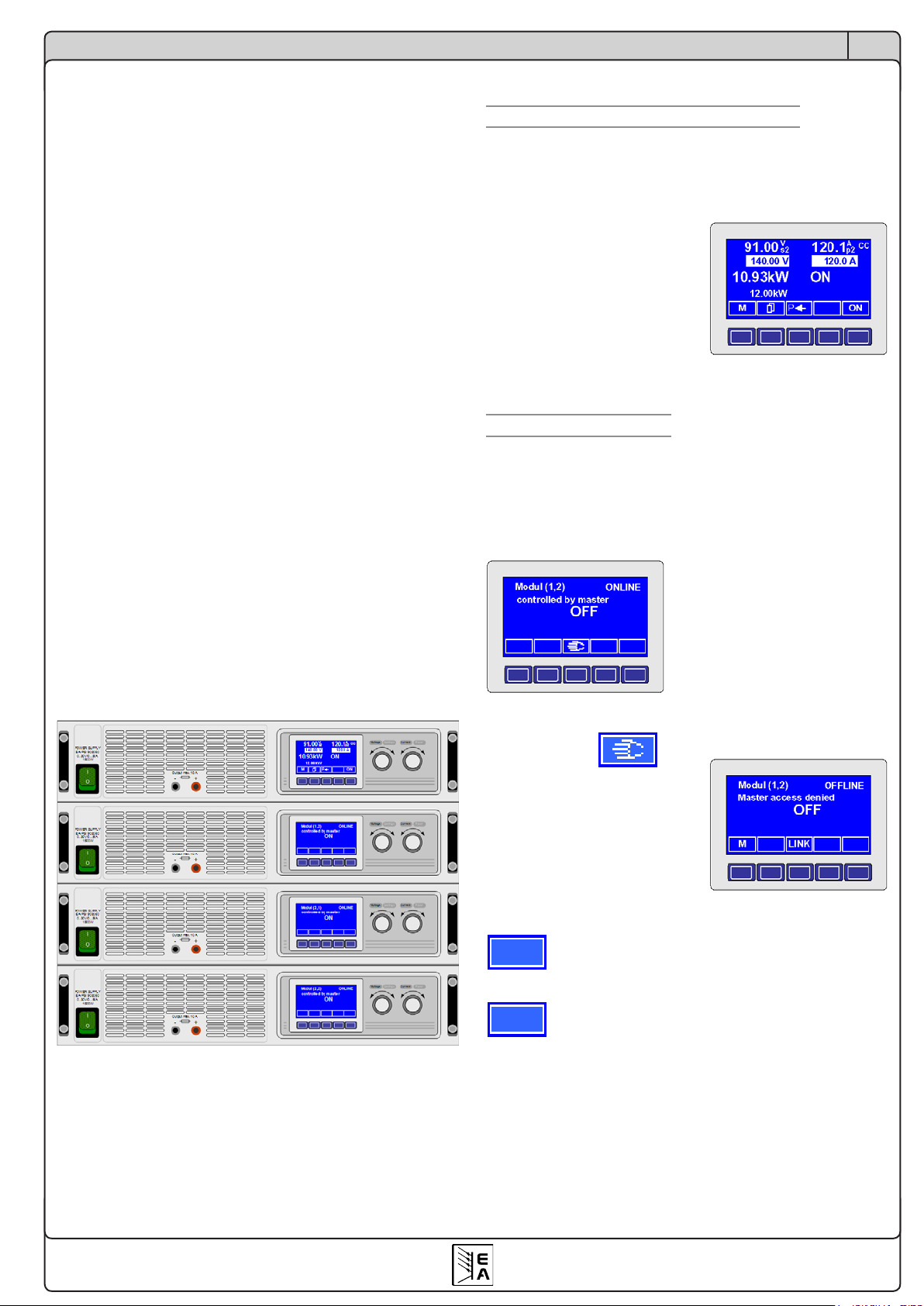
M
LINK
Über die Schnittstellenkarten
DE
6. Der System Link Mode (nur PSI 9000)
Der System Link Mode unterstützt die Reihen- und Parallelschaltung. Ohne die zusätzliche Schnittstelle (SIO2) zeigt
jedes Gerät die eigenen Istwerte an, wenn die Master-SlaveReihen- oder Parallelschaltung oder die Parallelschaltung
über den Share-Bus angewendet wird. Sollwerte und Istwerte
müssen somit bei der Reihenschaltung mit der Anzahl der
in Reihe geschalteten Geräte multipliziert werden, da nur
der Sollwert der einzelnen Gerätes einstellbar ist. Bei der
Parallelschaltung verhält sich der Stromsollwert in Analogie
zum Spannungssollwert bei der Serienschaltung.
Über den System Link Mode werden die Istwerte zur zentralen
Bedieneinheit (Master) und die Sollwerte zu den untergeordneten Modulen (Slaves) übertragen. Die einzelnen Istwerte
und Sollwerte aller miteinander verbundenen Geräte werden
vom Master angezeigt und gestellt, so daß das Stromversorgungssystem sich wie ein Einzelgerät verhält. Desweiteren
werden einfache Meldungen, Warnungen und Alarme vom
Slave zum Master weitergegeben. Über den Master können
solche Warnungen und Alarme quittiert werden.
Die Schnittstelle unterstützt bis zu 30 miteinander verbundene Geräte. Bei der Parallelschaltung sollten nicht mehr
als zehn Geräte parallel geschaltet werden.
Beispiel:
Es werden vier PSI 9080-100 zusammengeschaltet. Jedes
der vier Netzteile kann 3kW Leistung liefern. Bei einer Reihenschaltung von jeweils zwei parallel geschalteten Geräten ergibt sich eine maximale Spannung von 160V und ein
maximaler Strom von 200A bei einer Gesamtleistung von
maximal 12kW.
6.1 Bedienung des System Link Mode
6.1.1 Anzeige und Bedienung des Masters
Über das Mastergerät können die Sollwerte und alle anderen
Einstellmöglichkeiten auf das gesamte Stromversorgungssystem bezogen werden. Die Anzeige des Masters zeigt die
Istwerte des Systems an.
Die Konfiguration des Masters
bestimmt das Geräteverhalten.
Alle Einstellwerte können wie
bei einem Einzelgerät eingestellt
werden.
Der Master stellt die in Reihe
( s2) und die parallel (p2)
geschalteten Geräte dar.
6.1.2 Anzeige der Slaves
Sofern eine Onlineverbindung mit dem Master besteht, zeigt
der Slave dies an. Jedes Gerät muß konfiguriert werden;
welches der Master ist und wie die Slaves verteilt sind, damit
der Master „weiß“, wer mit wem in Reihe und wer parallel
geschaltet ist.
Beispiel: der Slave ist online
und der Leistungsausgang des
Systems ist ausgeschaltet.
Über die Taste kann
der Slave bei ausgeschaltetem
Ausgang „offline“ gesetzt werden, ist dann also nicht mehr
mit dem Master verbunden.
Jetzt ist es möglich, die Einstellungen zur Konfiguration vorzunehmen.
Über die MENU-Taste wird von der Betriebsanzeige
in die Menüebene gewechselt.
Über die LINK-Taste kann der Slave wieder mit
dem Master „online“ geschaltet werden.
© 2008, Elektro-Automatik GmbH & Co. KG
Irrtümer und Änderungen vorbehalten
25
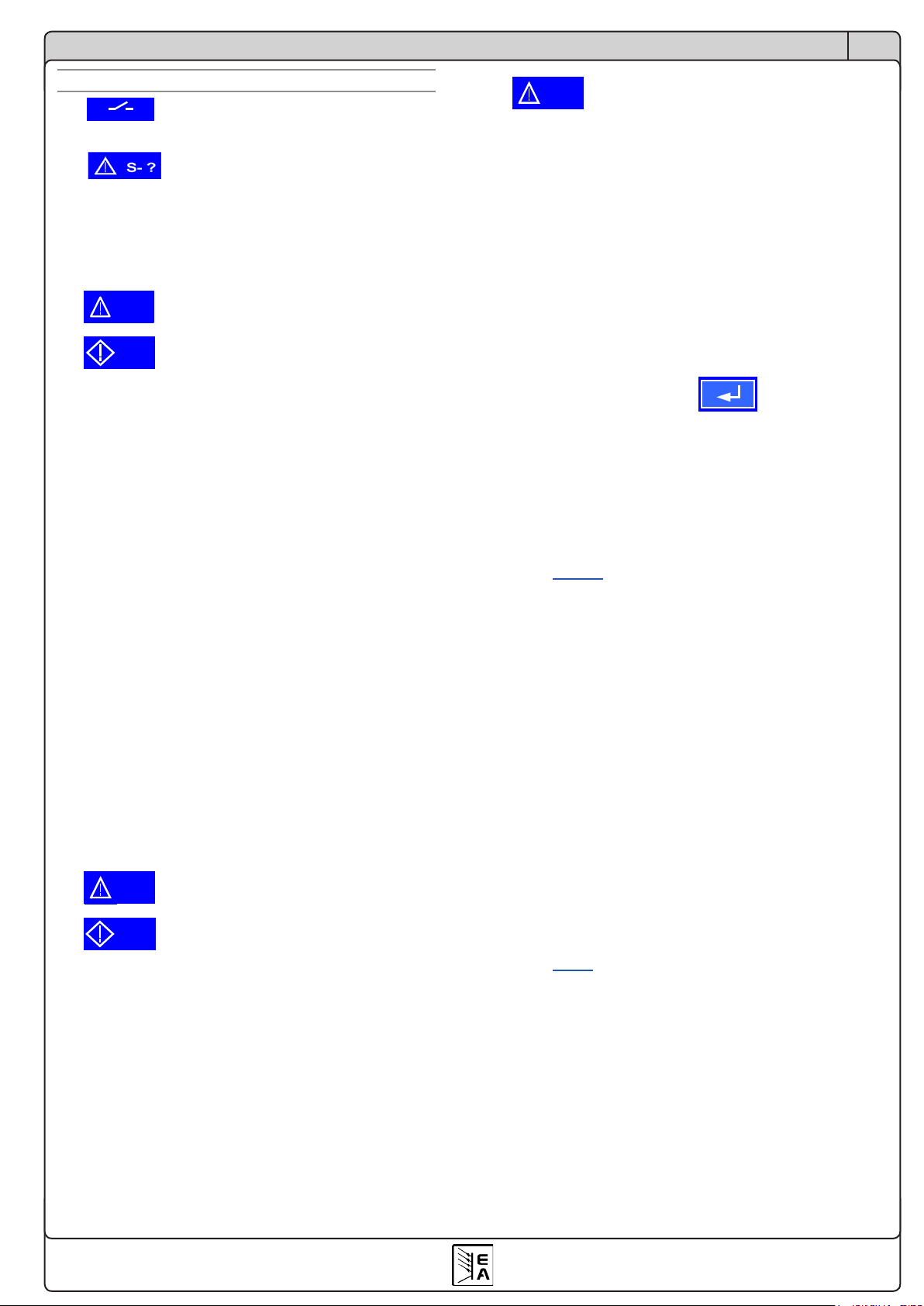
M S
S-PH
S-PH
S-OT
S-OT
Über die Schnittstellenkarten
S-OV
6.1.3 Spezielle Alarme, Warnungen und Meldungen
Slaves online sind.
Der Master meldet, dass nicht mehr alle
Alarm vom Slave
Ein Alarm wird ausgelöst, wenn ein Slave nicht mehr
adressiert werden kann während der Master den Ausgang
eingeschaltet hatte. Zum Beispiel wenn die Verbindung
unterbrochen oder der Slave über den Netzschalter ausgeschaltet wurde.
wird gemeldet, wenn die Verbindung zum Slave fehlt, falls
der Slave ausgeschaltet wurde oder seine Spannungs-versorgung weggefallen ist.
Ein Warnung mit „Auto ON“ Funktion schaltet den Ausgang
ab bis der Fehler behoben ist. Das Stromversorgungssystem
schaltet den Ausgang automatisch wieder ein. Der Fehler ist
zu quittieren und wird, falls er nach der Quittierung immer
noch besteht, in eine Meldung umgewandelt. Die Meldung
erlischt, sobald der Fehler behoben ist bzw. entfällt.
Ob nun ein Alarm oder eine Warnung mit „Auto ON“ ausgeführt wird, hängt von der Einstellung „Wiedereinschaltung bei
Power On“ ab (siehe Benutzerhandbuch PSI 9000, Abschnitt
„Betriebsparameter definieren“).
Ein Alarm oder
eine Warnung mit „Auto ON“ Funktion
Power ON Grundeinstellung: OFF
= OFF Leistungsausgang bleibt nach Netzwiederkehr
oder beim Einschalten des Gerätes ausgeschaltet.
= restore Leistungsausgang schaltet sich nach Netz-
wiederkehr oder beim Einschalten des Gerätes automatisch ein, wenn er vor Wegfall
des Netz oder vor dem letzten Ausschalten
eingeschaltet war.
wurde ausgelöst, da ein oder mehrere Slaves eine Übertemperatur ihres Leistungsteils festgestellt haben und melden.
Ob nun ein Alarm oder eine Warnung mit „Auto ON“ ausgeführt wird, hängt von der Einstellung „Wiedereinschaltung bei
Power On“ ab (siehe Benutzerhandbuch PSI 9000, Abschnitt
„Betriebsparameter definieren“).
Ein Alarm oder
eine Warnung mit „Auto ON“ Funktion
DE
Bei einem oder mehreren Slaves hat der OVP (Overvoltage
Protection) eine Alarmmeldung ausgelöst. Der Ausgang wird
abgeschaltet. Er kann erst nach Quittierung der Meldung
wieder eingeschaltet werden.
6.2 Konfiguration des System Link Mode
Um den System Link Mode nutzen zu können, müssen die
zusätzlichen Schnittstellen (SIO2) auf den IF-U1 oder IFR1-Karten miteinander, unabhängig von der Serien- oder
Parallelschaltung, über ein handelsübliches Patchkabel
CAT5 mit RJ45 Steckern verbunden werden. Die Endgeräte
erhalten einen Busabschluß, der über die Parameterseite
eingestellt werden muss.
Slot {A|B}: IF-R1 {IF-U1} +
SIO2 Grundeinstellung: not used
= not available
= not used
= {Master|Slave}
Die folgenden zwei Parameter sind nur sichtbar, wenn das
Gerät als Master deniertwurde.
Matrix of modules
Bei den nachfolgenden Einstellungen ist dem Master
bekannt zugeben, wieviele Geräte in Reihe und/oder
parallel liegen.
serial Grundeinstellung: 1
={1..x} Die Anzahl der zum Master in Reihe
Es gilt die maximal zulässige Isolationsspannung
zu beachten, wodurch nicht beliebig viele Geräte in
Reihe geschaltet werden dürfen!
parallel Grundeinstellung: 1
={1..30} Die Anzahl der zum Master parallel ge-
Die zwei folgenden Parameter erscheinen nur, wenn das
Gerät als Slave definiert wurde:
Position of module
Bei den nachfolgenden Einstellungen wird die Position
des Gerätes in der Reihen- und Parallelschaltung festgelegt. Innerhalb des Stromversorgungssystems darf
eine Position nur einmal vergeben werden.
Die SIO2 Schnittstelle ist nicht verfügbar.
Die SIO2 Schnittstelle wird nicht verwendet.
Das Gerät wird als „Master“ oder Slave
deniert.
geschalteten Geräte ist hier anzugeben.
schalteten Geräte, unabhängig davon ob
diese direkt zum Master verbunden sind,
ist hier anzugeben.
OT disappear Grundeinstellung: auto ON
= OFF Leistungsausgang bleibt auch nach Abkühlen
des Gerätes ausgeschaltet.
= Auto ON Leistungsausgang schaltet sich nach Abküh-
len des Gerätes bzw. nach Unterschreitung
der Übertemperaturschwelle automatisch
wieder ein.
© 2008, Elektro-Automatik GmbH & Co. KG
Irrtümer und Änderungen vorbehalten
serial Grundeinstellung: 1
={1..x} Die Position innerhalb der Verschaltung
der Geräte ist anzugeben.
Es gilt die maximal zulässige Isolationsspannung
zu beachten, wodurch nicht beliebig viele Geräte in
Reihe geschaltet werden dürfen!
26

Über die Schnittstellenkarten
DE
parallel Grundeinstellung: 1
={1..30} Die Position innerhalb der Verschaltung
der Geräte ist anzugeben.
Beispiel: zum Master ist ein Gerät in Reihe geschaltet und
zu diesem Gerät noch drei weitere parallel. Diese vier parallel geschalteten Geräte müssen dann für serial den Wert
2 bekommen und für parallel aufsteigende Werte von 1...4,
wobei die 4 dem entferntesten Gerät zugewiesen wird. Siehe
auch das Bild für ein anderes Beispiel:
Achtung! Die Position serial=1/parallel=1 ist fest an den
Master vergeben. Das als Slave konfigurierte Gerät wird
diese Einstellung nicht übernehmen.
7. Übersicht zur Kommunikation
Der Abschnitt 7. bezieht sich nicht auf die textbasierende
Kommunikation mit SCPI-Befehlen bei der GPIB-Karte
IF-G1!
7.1 Begriffserklärungen
Telegramm: Kette von Bytes, mit unterschiedlicher Länge.
Wird entweder zum Gerät gesendet oder vom Gerät empfangen.
Singlecast: Anfrage bzw. einfaches Senden an ein einzelnes Gerät. Bei in Reihe vernetzten Geräten, z.B. bei CAN,
geht das Telegramm an alle Geräte, wird aber nur von dem
adressierten Gerät akzeptiert. Betrifft nur CAN.
Broadcast: Anfrage bzw. einfaches Senden an alle Geräte.
Das heißt, alle am PC mittels der Schnittstellenkarten angeschlossenen Geräte bekommen nahezu gleichzeitig das
Telegramm. Betrifft CAN.
Multicast: wie Broadcast, aber nur an eine bestimmte Gruppe von Geräten, die durch das verschiebbare Adreßsegment
(RID) bestimmt wird. Betrifft nur CAN.
Objekt: beschreibt mit seinen Eigenschaften die Objektadresse und löst definierte Aktionen auf dem Zielgerät aus.
Nachricht (Message): Datenpaket bei CAN, wie ein Telegramm.
Die Schnittstelle SIO2 benötigt an den beiden Endgeräten
einen Busabschluß. Der Busabschluß kann über das Bedienmenü eingestellt werden.
bus terminate Grundeinstellung: NO
=NO Kein Busabschluß.
=YES D
ie SIO2 Schnittstelle wird abgeschlossen.
7.2 Vorwort
Das Kommunikationsprotokoll mit seiner objektorientierten
Telegrammstruktur ist sehr komplex. Es wird daher empfohlen, nach Möglichkeit die fertigen LabView-Bausteine
zu benutzen. Die Anwendung des Protokolls in anderen
Entwicklungsumgebungen, wie z.B. Visual Basic, C oder
.NET, erfordert Programmierkenntnisse über die Einrichtung
und Verwendung von Hardwareschnittstellen wie CAN oder
USB und das Ansprechen der entsprechenden Treiber. Hier
wird nur auf den Aufbau des Datenpakets (des Telegramms)
eingegangen und nicht darauf, wie es richtig an das Gerät
übertragen wird.
7.3 Allgemeine Hinweise zur Kommunikation
Die Firmware der verschiedenen Geräte, die mit den Schnittstellenkarten gesteuert werden sollen, ist so programmiert,
daß sie die Gegebenheiten und Probleme, die sich bei der
Ansteuerung von mehreren Geräten ergeben, so weit wie
möglich beachtet. Daher ist es nicht möglich, zu jeder Zeit
und bei jedem Zustand des Gerätes alle Objekte zu verwenden. So sind zum Beispiel die Daten für den Funktionsmanager der Serie PSI 9000 (siehe Benutzerhandbuch) nur im
Standby des Gerätes transferierbar, ansonsten kommt eine
Fehlermeldung zurück. Diese enthält einen Fehlercode, der
unter Anderem darauf hinweist, daß sich das Gerät möglicherweise nicht im Standby befindet.
© 2008, Elektro-Automatik GmbH & Co. KG
Irrtümer und Änderungen vorbehalten
7.4 Hinweise zum USB-Treiber
Der Hersteller des USB-Chips bietet für Windows 98/ME
zwei Treiber an, die auch auf der beliegenden CD im Ordner
software\usb_driver\ zu finden sind. Einer ist ein reiner USBTreiber und der andere erstellt auf dem PC pro USB-Karte
einen virtuellen COM-Port (VCP-Treiber). Für Windows
XP/2003/Vista sind die zwei Treiber in einem kombiniert.
27

Über die Schnittstellenkarten
DE
Die VCP-Funktion ist standardmäßig aktiviert.
Bei Programmierung eigener Anwendungen mit LabView
ist, je nach installiertem Treiber bzw. je nachdem welcher
Treiber genutzt werden soll, das USB- oder RS232-Kommunikations-VI zu verwenden. Die Einbindung des VCP-Treibers ist generell einfacher, dafür ist dieser Treiber anfälliger
für Fehler und Verbindungsprobleme. Außerdem wird für
jedes Gerät mit USB-Karte durch diesen Treiber ein neuer
COM-Port eingerichtet, was die Verwaltung erschwert. Beim
USB-Treiber ist es dagegen erforderlich, eigene Routinen
zu erstellen, die die Kommunikation mit der USB-Hardware
verwalten und den Transport der Kommunikationsdaten
unseres System sicherstellen. Diese Routinen werden von
uns nicht angeboten. Beispielcode ist aber auf der Webseite
des Herstellers FTDI unter www.ftdichip.com zu finden. Die
USB-Hardware heißt FT232BL.
7.5 Aufbau der Kommunikation
Die Kommunikation mit den zu steuernden Geräten basiert
auf diesen drei Telegrammformen:
a) einfache Sendung: es wird ein Objekt gesendet, das einen
Wert, z.B. Spannung, setzen soll. Sofern dies im momentanen Betriebszustand des Gerätes zulässig ist, wird das
Objekt akzeptiert und ausgeführt. Das Gerät sendet keine
Antwort. Falls die Ausführung momentan nicht zulässig ist,
kommt eine Fehlermeldung.
b) Anfrage: es wird mittels eines Objekts eine Anfrage an das
Gerät gesendet, worauf man eine Antwort erwartet. Ist die
Anfrage für den momentanen Betriebszustand des Gerätes
zulässig, wird sie ausgeführt und die Antwort gesendet, die
als Inhalt die angefragten Daten enthält. Falls nicht , wird
als Antwort eine Fehlermeldung gesendet.
c) Ereignis: ist eine Fehlermeldung, die unaufgefordert vom
Gerät gesendet wird, z.B. wenn der Zugriff auf ein Objekt
nicht möglich ist oder durch äußere Einflüsse eine Störung
der Datenkommunikation auftritt und das Gerät das Telegramm nicht erkennen kann bzw. falsch erkennt (Daten
verstümmelt). Enthält einen Fehlercode.
7.6 Telegrammaufbau IF-R1 und IF-U1
Die Schnittstellenkarten IF-R1 und IF-U1 arbeiten mit einer
gleichen, die Karte IF-C1 mit einer leicht abgewandelten
Telegrammstruktur. Lesen Sie im nächsten Abschnitt weiter,
wenn Sie eine IF-C1 Karte benutzen.
Bei der seriellen Übertragung eines Bytes über die RS232Karte werden folgende Bits übertragen:
Startbit + 8 Datenbits + Paritätsbit + Stoppbit
Das Parität wird auf ungerade (engl.=odd) geprüft.
Die USB-Karte arbeitet intern im Gerät mit der Übertra-
gungscharakteristik der RS232. Für beide Kartentypen sind
zur Konfiguration am jeweiligen Windowstreiber folgende
Parameter mindestens zu setzen:
Baudrate: 57600kBd
Parität: ungerade
Stoppbits: 1
Das Telegramm hat den folgenden Aufbau
SD + DN + OBJ + DATEN + CS
und setzt sich aus diesen Bytegruppen zusammen:
Byte 0: SD (start delimiter)
Der Startdelimiter zeigt den Beginn eines Telegramms an, die
Länge der Daten, den Absender und den Telegrammtyp.
Bits 0-3: Datenlänge (Bytes 3-18)
Geben die Datenlänge - 1 der Daten im Telegramm an.
Bei einer Anfrage steht hier die Länge -1 der zurücker-
warteten Daten.
Bit 4: Richtung
0 = Nachricht vom Gerät an die Steuereinheit
1 = Nachricht von der Steuereinheit an das Gerät
Bit 5:
0 =
Singlecast, Nachricht an einen bestimmten Empfänger
1 = Broadcast/Multicast, Rundnachricht an mehr als
einen Teilnehmer
Funktioniert nur bei untereinander verbundenen Geräten, z. B. im
CAN-Bus
Bits 6+7: Sendungstyp
00= reserviert
01= Anfrage von Daten
10= Antwort auf eine Anfrage
11= Daten senden (ohne vorherige Anfrage)*
* kann auch aus Richtung des Gerätes auftreten
Byte 1: DN (device node)
Über den Geräteknoten, den device node, wird das Gerät
in den Bussystemen adressiert. Ein Geräteknoten darf innerhalb eines Bussystems nur einmalig vergeben werden.
Wertebereich: 1...30, andere sind nicht gültig. Bei CAN
berechnet sich aus dem Geräteknoten die CAN-ID, mehr
dazu in Abschnitt 7.7.
Byte 2: OBJ (object)
Die Kommunikationsobjekte eines Gerätes werden über die
hier angegebene Zahl adressiert. In der Kommunikationsobjektliste (siehe Abschnitt 9.3) werden die weitere Funktion(en)
oder Eigenschaften der Objekte beschrieben.
Byte 3 - 18: Daten
Der Datenbereich kann 1-16 Bytes lang sein, die Länge des
Telegramms variiert also. Bei einer Anfrage (PC -> Gerät)
werden keine Daten übermittelt, der Datenbereich entfällt
dann und ab Byte 3 folgt direkt die Checksumme, siehe
unten. Nur bei einer Antwort (Netzgerät -> PC) oder einem
Ereignis werden Daten übermittelt.
Wort x: CS (check sum)
Die Position der Prüfsumme (check sum) ist stets am Ende
des Telegramms. Die Prüfsumme wird über die einfache
Addition aller Bytes des Telegramms gebildet. Sie ist zwei
Bytes lang. Das Highbyte wird vor dem Lowbyte gesendet
(Big Endian Order).
© 2008, Elektro-Automatik GmbH & Co. KG
Irrtümer und Änderungen vorbehalten
28

Über die Schnittstellenkarten
DE
Beispiel für ein Telegramm:
An ein Gerät mit Geräteadresse 1 soll das Objekt 71 gesendet werden (Istwerte anfragen). Das Telegramm müßte dann
so aussehen (Hexwerte):
55 01 47 00 9D
Die zu erwartende Antwort könnte so aussehen:
85 01 47 64 00 1E 00 50 00 01 9F
(das ergibt 80V, 30A und 2400W bei einem Netzgerät mit
80V, 100A und 3000W, wie z.B. PSI9080-100)
Siehe auch nächsten Abschnitt für die Umrechnung der
Werte. Weitere Beispiele in Abschnitt 9.
7.6.1 Sollwerte und Istwerte umrechnen
Die Sollwerte und Istwerte (siehe Kommunikationsobjektliste) werden, mit wenigen Ausnahmen, als Prozentwert
übertragen, wobei 0x6400 = 100% entspricht. Wenn also
ein Gerät eine Nennausgangsspannung von 80V hat, dann
würde der übertragene Spannungsistwert beim Wert 0x3200
der Spannung 40V entsprechen.
Das Highbyte ist die Prozentzahl (0x64 = dezimal 100) und
das Lowbyte die Nachkommastellen der Prozentzahl. Man
muß die eingehenden Istwerte sowie die ausgehenden
Sollwerte daher umrechnen.
Nennwert d. Gerätes * Prozent-Istwert
Istwert=
Beispiel: Nennwert des Gerätes ist 80V, der prozentuale Istwert kam als
0x2454 = 9300. Nach der Formel ergibt sich Istwert = (80 * 9300) / 25600
= 29,06V.
25600 * Sollwert
Prozent-Sollwert=
25600
Nennwert d. Gerätes
Mit einer CAN-Nachricht (Message) können maximal 8 Bytes
übertragen werden. Das erste Byte wird belegt durch die
Adresse des Kommunikationsobjekts. Danach können bis
zu 7 Datenbytes folgen (siehe Kommunikationsobjektliste).
Um ein Objekt mit einem 16 Byte großen Datenbereich zu
schicken sind also mindestens 3 Nachrichten nötig. Siehe
auch weiter unten.
Die anzugebende Datenlänge bezieht sich nur auf das aktuell
zu sendende (oder empfangende) Telegramm. Es können
in einem CAN-Telegramm grundsätzlich nur bis zu 8 Bytes
übertragen werden. Lesen Sie dazu auch den Abschnitt über
„Geteilte Telegramme“.
Zwei Beispiele:
a) das Gerät soll in den Remote-Betrieb gesetzt werden,
dieser ist erforderlich, um das Gerät zu steuern und Sollwerte
zu senden. Der device node wurde am Gerät auf 15 und die
RID auf 3 gesetzt. Da nur gesendet wird, ist der Nachrich-
tentyp Sendung. Es ergibt sich ein Identifier von 3 * 64 +
15 * 2 = 222d oder 0xDE, laut obenstehender Formel. Nach
der Objektliste im Abschnitt 9 wird das Objekt 54 (hex: 0x36)
mit den Datenbytes 0x10 (Maske) und 0x10 (set remote)
benötigt. Die sich ergebende Datenlänge ist 3. Somit sehen
die zu sendenden CAN-Daten so aus:
ID DL DATEN
DE 03 36 10 10
b) wollte man den Zustand des Gerätes nicht setzen, sondern abfragen, so wird laut der obigen Formel hier nun der
Identifier 0xDF verwendet und zwecks einer Anfrage reicht
die Objektnummer allein als Datum aus. Die sich ergebende
CAN-Nachricht für die Abfrage des Gerätezustands sieht
dann so aus:
DF 01 36
und die Antwort müßte dann so aussehen:
DF 01 36 10 10
Beispiel: der Sollwert soll 25,36V sein, der Nennwert d. Gerätes ist 80V.
Nach der Formel ergibt sich:
Prozent-Sollwert = (25600 * 25,36) / 80 = 8115 = 0x1FB3.
Das dezimale Ergebnis muß für die Hexzahl normal gerundet werden.
7.7 Telegrammaufbau IF-C1
Die Schnittstellenkarte IF-C1 unterstützt den CAN-Standard
2.0a. Das erweiterte Adreßformat wird nicht verwendet.
Der CAN-Treiberbaustein benötigt für eine Übertragung
den Identifier, bis zu 8 Datenbytes und die Datenlänge.
Der Identifier ist 11 Bit (CAN 2.0a) lang und wird durch den
device node, das verschiebbare Adreßsegment RID (Relo-
catable IDentifier) und den Typ der Nachricht gebildet. Für
jedes Gerät sind zwei Identifier vorgegeben (siehe auch
Abschnitt 4.3.1):
[RID*64 + device node * 2] und
[RID*64 + device node * 2 + 1],
wobei der erste Identifier nur für Objekte benutzt wird, die
Daten senden (Typ: Sendung) und der zweite (+1) für Objekte, die Daten anfragen (Typ: Anfrage).
7.7.1 Geteilte Telegramme
Bei einem geteilten Telegramm, d.h. einem Telegramm,
das sich aus mehreren Nachrichten zusammensetzt (nur
möglich bei Objekten im „String“-Format), wird nach der
Objektadresse eine weitere Kennung eingefügt. Die Kennung der ersten Nachricht ist 0xFF, der zweiten Nachricht ist
0xFE und die dritte Nachricht ist 0xFD. Diese Kennung hilft
dabei, diese Telegramme als aufgeteilt zu identifizieren und
deren Dateninhalt nach Empfang wieder richtig zusammen
zu setzen. Die Reihenfolge der Nachrichten ist nicht fest
vorgegeben. Bei Verwendung der Gateway-Funktion (nur
PSI9000) werden die geteilten Telegramme nicht vom Gateway zusammengesetzt. Dies muss in der übergeordneten
Steuereinheit geschehen.
© 2008, Elektro-Automatik GmbH & Co. KG
Irrtümer und Änderungen vorbehalten
29

Über die Schnittstellenkarten
DE
7.7.2 Timing von Telegrammen
Singlecast:
Nach jeder Anfrage benötigt das Gerät typisch 5ms und
maximal 50ms für eine Antwort. Grundsätzlich darf unmittelbar nach der Antwort wieder gesendet werden. Nach dem
Empfangen eines Ereignisses (Antworten ohne Anfrage)
muss mindestens 50 ms gewartet werden. Empfohlen wird
eine Zeit von 100 ms, damit das Gerät nicht zu sehr durch
die Kommunikation ausgebremst wird.
Bei der Gateway-Funktion (nur PSI9000) muß zudem die
Übermittlung der Telegramme von einem Bussystem auf das
andere Bussystem berücksichtigt werden. Hier kann sich die
Antwort bis zu 200 ms verzögern.
Nach dem Empfangen einer Fehlermeldung sollte mindestens 100ms gewartet werden.
Broadcast:
Nach jeder Rundumanfrage können die Busteilnehmer nur
nacheinander antworten. Abhängig vom Bussystem, der
Baudrate und der Anzahl der angesprochenen Busteilnehmer, sowie dem zusätzlichen anderen Datenverkehr wird
sich die Antwort mehr oder weniger verzögern. Da die Zeit
nur individuell zu spezifizieren ist, kann sie in erster Annäherung mit Busteilnehmeranzahl * Antwortzeit beim Single-
cast angenommen werden. In den meisten Fällen wird die
Antwortzeit aber wesentlich kürzer sein.
7.8 Telegrammaufbau IF-G1
Der Telegrammaufbau für die textbasierende Kommunikation
über eine IEEE-Karte ist im Abschnitt 4.5.7 beschrieben.
8. Kommunikation mit LabView
8.1 Übersicht Labview VIs
Zur Integration der Geräte in eigene Labview-Applikationen
werden mehrere Labview VIs zur Verfügung gestellt.
Mit den virtuellen Instrumenten (VI) ist eine einfache Einbindung und Programmierung einer Anwendung möglich,
ohne dass der Anwender sich in die unteren Ebenen der
Kommunikation einarbeiten muß. Sie erleichterten das
Einfügen in bestehende Anwendungen oder die Erstellung
eines anwenderspezifischen Programms.
Um die Funktionen der VIs nutzen zu können, wird die Softwareentwicklungsumgebung Labview der Firma National
Instruments benötigt. Die bereitgestellten Labview VIs sind
kompatibel mit der Version 7.0 oder höher. Auf Anfrage
können auch VIs bereitgestellt werden, die mit LabView 6.1
kompatibel sind.
Folgende minimale Systemvoraussetzungen sollten erfüllt
sein:
- Pentium 3 Prozessor mit 256 MB Hauptspeicher
- Windows Betriebssystem (Win98 oder WinXP)
Updates können über die Webseite www.elektroautomatik.
de heruntergeladen werden, sofern verfügbar.
8.1.1 Installation
Um die Labview VIs in Ihre Umgebung einzubinden lesen
Sie bitte die Installationshinweise in der Datei „installation_deutsch.pdf“ auf der beiliegenden CD.
Nach der Installation finden Sie die VIs in LabView normalerweise im Kontextmenü unter „Instrumenten-I/O -> Instrumententreiber -> IF-XX“.
Es gibt VIs, die nur für Geräte der Serie PSI9000 gedacht
sind und auch nur mit diesen funktionieren. Diese haben
das Kürzel PSI9 vor dem Namen und auch im VI-Icon. Dann
gibt es welche nur für die elektronische Lasten der Serien
EL3000 und EL9000. Diese haben das Kürzel EL vor dem
Namen und auch im VI-Icon. Weitere VIs ohne besonderes
Kürzel sind gemeinsam nutzbar. Funktion und Benutzung
sind im Handbuch zu den VIs beschrieben. Dieses rufen
Sie wie gewohnt über die LabView-Hilfe auf oder direkt aus
dem Ordner „\software\labview_7+\“ auf der CD. Je nach
Windowsversion kann es, auf Grund von Sicherheitseinstellungen des Internetexplorers, nötig sein, die Datei vor dem
Öffnen auf die Festplatte zu kopieren, damit Sie den Inhalt
sehen können.
Die VIs werden in drei Kategorien unterteilt:
1. Kommunikation-VIs
2. Standard-VIs
3. Spezial-VIs
© 2008, Elektro-Automatik GmbH & Co. KG
Irrtümer und Änderungen vorbehalten
Wichtig! Bitte verwenden Sie stets die richtigen VIs für
Ihr Gerätö.
Lesen Sie auch die LabView VIs Hilfedatei auf der beiliegenden CD, um einen Überblick über die Handhabung
der VIs zu bekommen.
30

LabView-Unterstützung
DE
8.1.2 Kurzinfo Kommunikations-VIs
Die Kommunikations-VIs dienen als Schnittstellentreiber für
die unterschiedlichen Bussysteme. Diese VIs sind die Basis
der Standard-VIs. Ohne eine im Hintergrund laufende Kommunikation können die Geräte nicht angesprochen werden.
Daher müssen diese VIs zwangsweise in der Applikation
verwendet werden und zwar vor der Benutzung eines der
anderen VIs. Für jede verwendete Schnittstelle gibt es ein
eigenes VI. Hier nur eine Übersicht der VIs, eine genauere
Beschreibung aller VIs befindet sich in der LabView-Hilfedatei zu den VIs, die sich auf der beiliegenden CD und bei
den installierten VIs befindet.
- CAN.vi
Lesen/Schreiben von Kommunikationsobjekten über das
CAN-Protokoll und IF-C1. Ist nicht ohne weiteres lauffähig,
da noch die Standard-CAN-VIs des Hardwareherstellers
eingesetzt werden müssen, von dem Sie Ihre CAN-Hardware haben.
- RS232.vi
Lesen/Schreiben von Kommunikationsobjekten über RS232
(COM-Port) und IF-R1.
- USB.vi
Lesen/Schreiben von Kommunikationsobjekten über den
USB und IF-U1
- Communication_layer.vi
Kernanwendung der Kommunikation, benötigt eins der
anderen drei VIs.
Bei den VIs „RS232“ und „USB“ können bis zu 29 weitere
Netzteile gesteuert werden, falls das angesprochene Gerät als Gateway zum CAN-Bus parametriert wurde (siehe
„4.3 CAN-Karte IF-C1“). Die Gateway-Funktion ist nur bei
geringem Datenverkehr über den CAN-Bus empfehlenswert, denn die Kommunikation direkt über den CAN-Bus
ist leistungfähiger. Dazu wird allerdings eine CAN-Karte im
PC benötigt.
8.1.3 Kurzinfo Standard VIs
Die Standard VIs bestehen aus den am häufigsten verwendeten VIs, die Werte im Gerät setzen bzw. aus dem Gerät
lesen.Sie können beliebig oft eingesetzt werden und dürfen
nur dann parallel ausgeführt werden, wenn mehrere Geräte
angesprochen werden. Diese VIs bauen auf die Kommu-nikations-VIs auf, sind also davon abhängig, daß mindestens
eines davon, je nach verwendeter Karte, im Hintergrund
richtig läuft.
Hier nur eine Übersicht der wichtigsten VIs, eine genauere
Beschreibung aller VIs befindet sich im Handbuch zu den
LabView VIs.
- init.vi
Wird nur einmal beim Start der Applikation verwendet (wenn
die Kommunikation bereits läuft) und initialisiert die angeschlossenen Geräte in dem es feststellt, welche und wieviele
Geräte angeschlossen sind. Weiterhin werden benötigte
Werte und Daten aus den Geräten gelesen und intern an
die anderen VIs weitergegeben.
- set_mode.vi
Setzt den Modus des Gerätes in Bezug auf die externe
Steuerung. Es gibt zwei Zustände, „Standby“ und „Remo-
te“. Standby schaltet den Leistungsaus- bzw. eingang des
Gerätes ein/aus. „Remote“ setzt das Gerät in den Fernsteu-
er-Modus. Nur wenn dieser aktiviert wurde, kann das Gerät
gesteuert werden. Ohne können nur Anfragen gesendet
werden, wie z.B. Istwerte auslesen.
Der Fernsteuer-Modus kann jedoch nur aktiviert werden,
wenn das Gerät im Normalmodus arbeitet, sprich nicht „lokal“ gesetzt wurde oder durch einen anderen, besonderen
Zustand blockiert wird. Zudem ist gleichzeitiges Setzen von
Remote und Eingang/Ausgang nicht möglich!
- wr_set_values.vi
Setzt die Sollwerte für U/I/P/R, je nach Art des Gerätes kann
die Anzahl der setzbaren Sollwerte variieren. Erfordert den
Fernsteuer-Modus. Es werden nicht alle Werte auf einmal
übertragen, sondern es wird pro Sollwert ein Telegramm
gesendet. Wenn ein Sollwert nicht gesendet werden soll,
muß das Senden einfach mit einem zugehören „Enable“Bit deaktiviert werden. Die Grenzen für die einzugebenden
Werte sind automatisch mit der Initialisierung (init.vi) gesetzt, zu hohe Werte werden auf den maximalen Nennwert
gesetzt. Dies ist ein einfaches Senden, das keine Antwort
generiert.
- actual_values.vi
Fragt die Istwerte des Gerätes ab. Je nach Gerätetyp er-
gibt sich eine unterschiedliche Anzahl von Istwerten, deren
Wertigkeit innerhalb der Gerätenennwerte liegen muss.
Diese Istwerte sollten stets mit denen am Gerät gezeigten
übereinstimmen.
8.1.4 Verwendung
Zur Funktion der einzelnen VIs lesen Sie bitte auch die LabView-Hilfedatei, die Sie nach der Installation der VIs im Pfad im
Unterordner \data finden oder auf der beiliegenden CD finden.
Wichtig! Es gilt folgendes:
- die Kommunikations-VIs (CAN.vi, USB.vi, RS232.vi, jeweils
nur eins dieser auf einmal nutzbar) sowie das communication_layer.vi müssen verwendet werden
- die Kommunikations-VIs dürfen nicht in einer Sequenz,
einem Case oder einer Schleife plaziert werden
- zum Ansprechen eines Gerätes ist nach dem Start der Kommunikation das Gerät zunächst mit psi9_init.vi bzw. el_init.vi
zu initialisieren, dies sollte nur einmal ausgeführt werden
- alle anderen VIs können während der Laufzeit beliebig
verwendet werden (in einer Schleife z.B.), denn die Kommunikation verwaltet den zeitlichen Ablauf selbsttätig und gibt
eventuell auftretende Fehlermeldungen zurück
- parallel plazierte VIs, die z. B. bei mehreren Geräten gleichzeitig Istwerte abfragen sollen, werden intern nacheinander
abgearbeitet, da die Kommunikation immer nur ein Gerät
ansprechen kann, auch bei Broadcast; dies gilt für USB und
RS232, bei IEEE gibt es kein Broadcast.
© 2008, Elektro-Automatik GmbH & Co. KG
Irrtümer und Änderungen vorbehalten
31

Programmierung
DE
9. Kommunikation ohne Labview
9.1 Grundlegendes
Im Folgenden wird auf den Aufbau der Telegramme, die
Abhängigkeiten der Kommunikation vom Zustand des zu
steuernden Gerätes und Probleme mit der Kommunikation
eingegangen, ohne detailliert zu erläutern, wie z. B. bei USB
der USB-Treiber anzusprechen ist bzw. wie eine komplette
CAN-Nachricht gebildet wird. Dies ist vom Anwender und
abhängig von der Einsatzsituation unserer Geräte selbst in
Erfahrung zu bringen.
9.1.1 Hinweis zum USB-Treiber
Auf der beiliegenden CD befindet sich im Ordner \manuals\
other\ftdi ein PDF, daß die Funktionen zum Ansprechen des
Treibers beschreibt. Generell gilt, daß ein Gerät (in dem Fall
die USB-Hardware) zuerst zu öffnen ist (FT_Open o.ä.), dann
zu konfigurieren (FT_SetBaudRate, FT_SetDataCharacteristics und eventuell noch andere) und dann geschrieben
(FT_Write) oder gelesen werden (FT_GetQueueStatus,
FT_Read) kann. Wird das Gerät nicht mehr benutzt, sollte es
geschlossen werden (FT_Close). Die Funktionen FT_Write
und FT_Read dienen zum Transport der Telegrammbytes der
eigentlichen Kommunikation, die in den diesen Abschnitten
beschrieben wird.
9.2 Erstellen von Telegrammen
Das Programmieren der unterschiedlichen Geräte, in denen
die Schnittstellenkarten verwendet werden, erfolgt stets nach
dem gleichen Schema, wenngleich sich Anzahl und Funktion der Kommunikationsobjekte, die durch eine bestimmte
Geräteserie unterstützt werden, unterscheiden.
Generell gilt:
- Überwachung (Monitoring), also reine Abfrage von Istwer-
ten und Status, ist immer möglich. Die Geräte benötigen
dazu keinen Remote-Modus
- Setzen von Zuständen und Sollwerten (Controlling)
erfordert die Aktivierung des Remote-Modus (remote =
ferngesteuert durch eine digitale Schnittstelle)
- der Remote-Modus kann durch bestimmte Umstände blok-
kiert werden, z. B. expliziter Lokalbetrieb (nur PSI9000)
oder wenn sich ein Gerät in einer Betriebsart befindet, die
keinen Remote-Modus zuläßt bzw. eine derartige Anfrage
ignoriert. Näheres dazu entnehmen Sie bitte der Bedienungsanleitung Ihres Gerätes.
Um ein Gerät zu steuern, sprich z. B. einen Sollwert zu
senden und zu setzen, müssen Sie
1. den Remote-Modus aktivieren (Objekt 54)
2. den Sollwert senden
3. den Eingang/Ausgang einschalten (wenn nicht bereits)
Der Remote-Modus sollte verlassen werden, wenn er nicht
mehr benötigt wird. Solange er aber aktiviert ist, kann das
Gerät nicht oder nur bedingt manuell bedient werden. Der
Modus wird in der Anzeige des Gerätes angezeigt.
Beispiel 1: Remote-Modus aktivieren über IF-R1/IF-U1
Nach der Vorgabe des Telegrammformats (siehe auch 7.5)
ist das erste Byte der Startdelimiter, der von der Richtung
des Telegramms und dem Anfragetyp abhängig ist. Für
dieses Beispiel ergibt sich ein SD von 0xD1, in Bits zerlegt
sieht das so aus:
11 01 00 01
Bits 0...3: 1 = es werden 2 Bytes gesendet
Bit 4: 1 = vom PC gesendet
Bit 5: 0 = Singlecast
Bit 6+7: 11 = Daten senden
Alternativ zum bitweisen Zusammensetzen kann man sich
das vereinfachen, indem man Hexwerte addiert. Ausgehend
von Bit 6+7 ergibt sich folgendes:
SD = Sendungstyp + Castform + Richtung + Datenlänge
wobei Sendungstyp entweder
0xC0 Daten senden oder
0x40 Anfrage
und Castform entweder
0x00 Singlecast oder
0x20 Broadcast
und Richtung entweder
0x10 vom PC ans Gerät oder
0x00 vom Gerät an den PC
und die Datenlänge - 1 von
0x00...0x0F bis zu 16 Bytes am Stück (bei CAN siehe
„7.6.1 Geteilte Telegramme“).
Die Datenlänge entspricht der Anzahl der gesendeten
Bytes -1!! Immer beachten!!
Die Geräteadresse des anzusprechenden Gerätes ist beispielsweise 5, das zu benutzende Objekt 54 (als Hexwert
0x36), die Maske für den Remote-Modus (siehe auch Tabelle
in 9.3) ist 0x10 und das Steuerbyte für Remote auch 0x10.
Somit ergibt sich dieses Telegramm:
D1 05 36 10 10 01 2C
Zum Umkehren des Ganzen, also der Deaktivierung, ist dann
D1 05 36 10 00 01 1C zu senden. Die Maske bleibt natürlich
gleich, nur das Steuerbyte ändert sich.
Beispiel 2: Istwerte abfragen über CAN
Bei CAN entfallen der Startdelimiter SD und die Checksumme CS, somit benötigen wir nur das Objekt, laut Tabelle 71
(hex = 0x47), den Identifier ID (Berechnungsbeispiel siehe
Abschnitt 7.6) und die Länge der zu sendenden Bytes. Bei
der CAN-Nachricht zählt das Objekt zur Datenlänge, daher
ergibt sich hier eine Datenlänge von 1, weil hier nur das
Objekt zur Anfrage der Istwerte gesendet wird.
Weiter nächste Seite...
© 2008, Elektro-Automatik GmbH & Co. KG
Irrtümer und Änderungen vorbehalten
32

Programmierung
DE
Geräteadresse (device node) auch hier 5, der RID sei mal
auf 8 gesetzt. Gemäß der Formel aus Abschnitt 7.6 ergibt
sich ein Identifier von 8 * 64 + 5 * 2 +1 = 523 (hex = 0x20B).
Die +1 deshalb, weil es eine Anfrage ist. Wir schicken also
an ID 0x20B ein Byte. Die CAN-Nachricht sieht dann für
den User so aus:
02 0B 01 47
Objekt 71 (0x47), Anfrage Istwert
Datenlänge = 1
Identifier
Achtung! Das ist nicht die Byte/Bitaufteilung, die über
den CAN-Bus übertragen wird. Ein CAN-Controller fügt,
je nach Betriebsart, diverse Steuerbits in die Nachricht
ein und hängt an das Ende eine Checksumme. Hier wird
nur gezeigt, was man als User an den CAN-Controller
schicken müßte.
Eine mögliche Antwort auf diese Anfrage könnte so aussehen:
02 0B 06 64 00 0A 00 42 AA
Gleicher Identifier, Datenlänge ist 6, weil immer drei 16-BitIstwerte übertragen werden. Die Istwerte werden als Prozentzahlen übertragen und müssen entsprechend des Typs
des Gerätes zurückgerechnet werden. Siehe dafür Abschnitt
„7.5.1 Werte umrechnen“. Für eine EL 9080-200 ergäben
sich hier 100% für Spannung (=80V), 10% für Strom (=20A)
und 66,7% für die Leistung (=1600W).
Die Gerätenennwerte, also Nennstrom, Nennleistung und
Nennspannung, können mit entsprechenden Objekten aus
dem Gerät gelesen werden und zur Umrechnung benutzt
werden.
9.2.1 Das Zeitformat
Dieses Zeitformat läßt mit einem 16bit-Wert Zeiten zwischen
1µs und 100h zu. Zeitwerte werden vom Gerät, an das sie
übertragen werden, auf Plausibilität geprüft. Zu hohe bzw.
zu niedrige Werte werden nicht akzeptiert und es wird mit
einer Fehlermeldung geantwortet. Die oberen 4 Bits des 16Bit-Wertes werden als Maske für den Zeitbereich genutzt,
die restlichen Bits für den Zeitwert selbst. Das Zeitformat
wird für das Lesen und Setzen von Werten gleichermaßen
benutzt.
Das Zeitformat ist gültig für alle Geräte, bei denen irgendeine
Funktion Zeitwerte benutzt, sofern diese fernsteuerbar/auslesbar. Die Auflösung der Zeitbereiche in der Tabelle unten
deckt sich nicht immer mit der Auflösung der Zeitwerte am
Gerät. Für diesen Fall werden an das Gerät gesendete Zeitwerte gerundet. Ein Beispiel: es wird der Zeitwert 0x23E7
an eine elektronische Last geschickt. Das sind laut Tabelle
999 x 1µs = 999µs. Die manual am Gerät einstellbare Zeit
in diesem Zeitbereich ist aber 0,95ms oder 1ms. Die 999µs
werden auf 950µs abgerundet. Deswegen wird auch, wenn
der Zeitwert zurückgelesen wird, nicht 0x23E7 sondern
0x23B6 (=950) geantwortet.
Es werden nicht von jedem Gerät alle Zeitschlüssel
verwendet.
Für die elektronischen Lasten und die Anstiegszeit (Objekt
92) gilt, gemäß der Tabelle unten:
Zeitbereich Schrittweite
Zeitbereichsschlüssel**
am Gerät
30µs ... 99µs 1µs 0x2000
0,10ms ... 0,99ms 10µs 0x2000
1,0ms ... 9,9ms 100µs 0x3000
10ms ... 99ms 1ms 0x6000
100ms ... 200ms
** Werte, die von der Schrittweite abweichen, werden bei Empfang vom Gerät abgerundet
1ms 0x7000
Für die elektronischen Lasten und die Pulsbreite (Objekte
90 und 91) gilt, gemäß der Tabelle unten:
Zeitbereich Schrittweite
Zeitbereichsschlüssel**
am Gerät
0,05ms ... 0,95ms 50µs 0x2000
1,00ms ... 9,95ms 50µs 0x3000
10ms ... 99,9ms 100µs 0x6000
100ms ... 999ms 1ms 0x7000
1,00s ... 9,99s 10ms 0x4000
10,0s ... 100s 100ms 0x9000
** Werte, die von der Schrittweite abweichen, werden bei Empfang vom Gerät abgerundet
Beispiel 1: Sie möchten bei einer elektronischen Last die
Anstiegszeit auf 75ms setzen. Bei 75ms ist die Auflösung an
der Last 1ms. Es ist der also Zeitbereich 0x6000 zu nehmen.
Dessen Auflösung ist 0,1ms, daher ergibt sich ein Wert von
750 (75ms : 0,1ms), das entspricht 0x2EE. Mit dem Schlüssel
müßte dann also 0x62EE als Zeitwert für die Anstiegszeit
(Objekt 92) gesendet werden. LabView-Nutzer müssen die
Zeit anders vorgeben, siehe VI-Beschreibung.
Zeitschlüssel * Zeitwert (Bits 11..0) Auösung resultierende Zeitbereich
Bits 15..13(1 oder 15..12
0x2000
0x3000
0x6000
0x7000
0x0000
0x4000
0x8000
0x9000
0xC000
Tabelle: Zeitformat
* Wenn der Schlüssel ausmaskiert werden soll, um empfangene Zeitwerte in reale Zeitwerte umzurechnen, sind entweder die Bits 15...13 oder 15..12 relevant, je nach Zeitbereich
© 2008, Elektro-Automatik GmbH & Co. KG
Irrtümer und Änderungen vorbehalten
(1
(2
(1
(2
(1
(1
(1
(2
(1
(2
min.(dez) min.(hex) max.(dez) max.(hex)
0 0x00 999 0x3E7 1us 0 ... 0,999ms
100 0x64 999 0x3E7 10us 1ms ... 9,99ms
100 0x64 999 0x3E7 100us 10ms ... 99,9ms
100 0x64 999 0x3E7 1ms 100ms ... 999ms
0 0x00 4999 0x1387 2ms 0 ... 9,998s
100 0x64 5999 0x176F 10ms 1,00s ... 59,99s
1 0x01 3599 0xE0F 1s 1s ... 59min:59s
100 0x64 1000 0x3E8 100ms 10,0s ... 100,0s
60 0x3C 5999 0x176F 1m 01:00h ... 99:59h
33

Programmierung
DE
Beispiel 2: Der Zeitwert des Batterietests (elektronische
Last) wird ausgelesen und soll umgerechnet werden. Beim
Batterietest ist die Auflösung 1s. Da die Zeitbereiche die
Auflösung von 1s nur bis zu 1 Stunde zulassen und darüber hinaus in Minuten aufgelöst wird, würde der Zeitwert
0x8743 einer Zeit von 1859s oder 30m59s entsprechen, der
Zeitwert 0xC532 dann 1330m oder 22h10m. Die Sekunden
werden im Zeitbereich 0xC000 nicht angegeben, man würde
also eine Minute lang immer den gleichen Zeitwert geliefert
bekommen.
Beispiel 3: Setzen der Pulsbreite für A (Objekt 90) auf 5s.
Laut obiger Tabelle ergibt sich der Zeitbereichsschlüssel
0x4000. Mit der für diesen Zeitbereich geltenden Auflösung
von 10ms ergibt sich der Wert 500 (5s : 0,01s), in hexadezimal 0x1F4. Der resultierende Zeitwert wäre daher 0x41F4.
9.2.2 Tipps
I. Geräteadresse eines Gerätes ermitteln (nicht bei GPIB)
Wenn Sie z. B. ein Gerät über USB steuern möchten und
dessen Geräteadresse nicht kennen, können Sie zuerst
eine Anfrage mit der Broadcastadresse 0 stellen, z. B. die
Geräteklasse abfragen. Das Gerät wird in der Antwort dann
die am Gerät eingestellte Adresse (device node) mitsenden,
die dann für zukünftige Befehle verwendet werden kann.
II. Remote und Standby
Mit dem Objekt 54 wird der Fernsteuerbetrieb (Remote)
aktiviert oder der Eingang/Ausgang des Gerätes ein- bzw.
ausgeschaltet. Die Verwendung des Objektes und der Maske
lassen es zwar zu, daß im Steuerbyte beides gleichzeitig
gesetzt/zurückgesetzt werden kann, dies ist aber nicht zu
empfehlen! Setzen des Eingangs/Ausgangs erfordert, daß
bereits Remote aktiv ist und sollte daher nach der Aktivierung von Remote durch erneutes Senden des Objektes 54
geschehen. Natürlich nur mit dem entsprechende Bit. Beim
Beenden des Fernsteuerbetriebes umgekehrt genauso.
Wenn Sie beide Bits gleichzeitig setzen, kann es vorkommen,
daß das Gerät zuerst den Ausgang/Eingang setzen will, bevor Remote aktiv ist und das wird mit einer Fehlermeldung
quittiert. Daher ist es auch sinnvoll, nach dem Setzen des
Ausgangs/Eingangs, dessen Status durch das Objekt 70
zurückzulesen.
9.2.3 Hilfe bei Problemen
Problem: Das Gerät läßt sich gar nicht ansprechen bzw.
antwortet nicht.
Mögliche Ursachen bei USB
• Für die USB-Karte wird ein Treiber benötigt, prüfen Sie ob
dieser korrekt installiert ist und ob Sie das Gerät im Windows
Gerätemanager gelistet sehen.
• Der USB-Treiber kann als reiner USB-Treiber benutzt werden oder auch für jedes Gerät einen COM-Port erzeugen,
für den man dann nicht den USB-Treiber ansprechen muß
(nicht LabView) bzw. das RS232.vi statt des USB.vi benutzen
muß (LabView).
• Es wird die falsche Geräteadresse (device node) verwendet, um das Gerät anzusprechen.
Mögliche Ursachen bei RS232
• Für die RS232-Karte wird kein 1:1 Kabel verwendet.
• Es wird die falsche Geräteadresse (device node) verwendet, um das Gerät anzusprechen.
• Für Gerät und PC unterschiedliche Baudraten o.ä. eingestellt.
• Das verwendete Kabel ist zu lang für die eingestellte Baudrate (siehe auch Abschnitt 2.).
Mögliche Ursachen bei GPIB
• Wenn sich mehrere Geräte am IEEE-Bus befinden sind
möglicherweise eine oder mehrere Adressen doppelt belegt.
• Es wird die falsche Syntax verwendet, z. B. reagiert eine
elektronische Last auf den Befehl OUTP nicht, da sie einen
Eingang hat, oder es werden Befehle verwendet, die für das
angesprochene Gerät nicht gültig sind.
Mögliche Ursachen bei CAN:
• Es wird die falsche CAN-ID verwendet. Siehe Abschnitt
4.3.1 für die Berechnung der korrekten CAN-ID.
• Falsche Baudrate eingestellt oder falschen Sample point
gewählt (nur bei PSI 9000, siehe Gerätehandbuch).
• Das Gerät ist am Ende des Busses und nicht terminiert.
Problem: Es wurden mehrere Anfragen gestellt, aber nicht
alle wurden beantwortet
Ursache: Die Anfragen wurden zu schnell nacheinander ge-
stellt. In Abhängigkeit von der verwendeten Übertragungsartund geschwindigkeit und der Verarbeitungszeit des Befehls im
Gerät ist zwischen zwei Befehlen eine gewisse Zeit zu warten.
Faustformel: Wartezeit = Übertragungszeit + Ausführungszeit
Die Ausführungszeit liegt bei typ. 5-20ms, jenachdem ob nur
angefragt wurde oder etwas gesetzt werden soll.
Problem: Sollwerte oder Status werden nicht gesetzt
Mögliche Ursachen
• Das angesprochene Geräte befindet sich nicht im Fernsteuerbetrieb oder kann nicht in diesen gesetzt werden, weil
dies für den momentanen Zustand nicht zulässig ist oder
eine andere Bedingung für das Setzen eines Status ist nicht
erfüllt (siehe auch Abschnitt 9.)
• Die gesendeten Werte sind falsch (zu groß, zu klein) oder
deren Standardwertebereich (0...0x6400 bei Spannung,
Strom usw.) ist zusätzlich durch Grenzwerte (nur bei PSI
9000) eingeschränkt. Es wird dann eine Fehlermeldung
gesendet.
© 2008, Elektro-Automatik GmbH & Co. KG
Irrtümer und Änderungen vorbehalten
34

Programmierung
Hex. Dez. Hex. Dec.
1 1 RS232: Paritätsfehler 1 1 RS232: Parity error
2 2 RS232: Frame Error (Startbit o. Stopbit nicht erkannt) 2 2 RS232: Frame Error (Startbit or Stopbit incorrect)
3 3 Prüfsumme nicht korrekt 3 3 Check sum incorrect
4 4 Startdelimiter falsch 4 4 Start delimiter incorrect
5 5 CAN: max. Nodes überschritten 5 5 CAN: max. nodes exceeded
6 6 CAN: Node unbekannt/keine Gatewayfunktion 6 6 CAN: node unknown/no gateway present
7 7 Objekt nicht definiert 7 7 Object not defined
8 8 Objektlänge nicht korrekt 8 8 Object length incorrect
9 9 Schreib-Leserechte verletzt, kein Zugriff 9 9 Read/Write permissions violated, no access
0A 10 CAN: Gateway überlastet 0A 10 CAN: Gateway overload
0B 11 CAN: Gateway-Sendepuffer voll 0B 11 CAN: Gateway send buffer full
0C 12 CAN: geteilte Message abgebrochen 0C 12 CAN: Split message aborted
0D 13 CAN: Messagebuffer überlaufen 0D 13 CAN: Message buffer overflow
0E 14 CAN: String-Startkennzeichen nicht korrekt 0E 14 CAN: String identifier incorrect
0F 15 Gerät ist in "Local" Modus 0F 15 Device is in "local" mode
10 16 CAN-Treiber-IC: Stuffing Fehler 10 16 CAN driver chip: Stuffing error
11 17 CAN-Treiber-IC: CRC-Summenfehler 11 17 CAN driver chip: CRC sum error
12 18 CAN-Treiber-IC: Übertragungsfehler 12 18 CAN driver chip: Form error
13 19 CAN: erwartete Datenlänge stimmt nicht 13 19 CAN: expected data length incorrect
14 20 CAN-Treiber-IC: Puffer voll 14 20 CAN driver chip: Buffer full
20 32 Gateway: CAN Stuffing Fehler 20 32 Gateway: CAN Stuffing error
21 33 Gateway: CAN CRC-Summenfehler 21 33 Gateway: CAN CRC check error
22 34 Gateway: CAN Übertragungsfehler 22 34 Gateway: CAN form error
30 48 Obere Grenze des Objektes überschritten 30 48 Upper limit of object exceeded
31 49 Untere Grenze des Objektes unterschritten 31 49 Lower limit of object exceeded
32 50 Zeitdefinition nicht eingehalten 32 50 Time definition not observed
33 51 Zugriff auf Menüparameter nur bei "Ausgang aus" 33 51 Access to menu parameter only in standby
34 52 Zugriff auf Sequenzsteuerelemente verweigert 34 52 Access to sequence control denied
36 54 Zugriff auf Funktionsdaten verweigert 36 54 Access to function data denied
37 55 Zugriff auf Sollwert verweigert (Gerät im Slavemodus) 37 55 Access to set value denied (device is in slave mode)
Legende Legend
Kommunikationsfehler Communication error
Userfehler User error
Interner Fehler Internal error
Description
Fehlercode
Error code
Beschreibung
Problem: Eine Fehlermeldung wurde zurückgegeben
Fehlermeldungen sollten stets darauf hinweisen, wo der
Fehler liegt. In der nachstehenden Tabelle befindet sich eine
Übersicht über mögliche Fehlermeldungen, die vom anzusprechenden Gerät an den PC geschickt werden können.
Manche Fehler sind bedingt durch eine fehlerhafte Anfrage/Sendung, andere können ohne Aufforderung vom Gerät
kommen. Sie dienen als Hinweis und zur Fehlerfindung.
Fehlermeldungen haben Telegrammformat, d.h. sie bestehen
aus Startdelimiter, Objektnummer (hier als Kennzeichnung
für einen Fehler immer 0xFF) und Datenbereich. Der Datenbereich enthält den Fehlercode.
Beispiel: wenn man z. B. mit Objekt 50 bei einem Gerät
die Spannung setzen will und das Gerät nicht im RemoteModus ist, dann würde sich bei einer Geräteadresse 7 das
Fehlertelegramm C0 07 FF 09 01 CF ergeben.
Erläuterungen zu einigen Fehlercodes:
Code 0x7: die Objektnummer im Telegramm an das Gerät
ist dem Gerät unbekannt.
Code 0x8: die Länge des Datenfeldes im Telegramm ist in
der Objektliste definiert. Dieser Fehler kommt z. B., wenn ein
Sollwert (immer 2 Bytes bei Typ „Int“) gesendet werden soll,
das Datenfeld aber nur ein Byte enthielt. Selbst wenn der
Startdelimiter die richtige Telegrammlänge enthält, dies dient
zusätzlich zum Schutz, daß falsche Werte gesetzt werden.
Code 0x9: es wurde z. B. ein Objekt zum Setzen eines
Sollwertes gesendet, das Gerät ist aber nicht im Fernsteuerbetrieb. Daher nur Leserecht, kein Schreibrecht.
Codes 0xB/0xD/0x14: Nachrichten werden erst aus dem
Nachrichtenspeicher gelöscht, wenn sie ausgeführt wurden.
Kommen sie zu schnell herein und können nicht ausgeführt
werden, ist der Speicher irgendwann voll und kann keine
neuen Nachrichten mehr aufnehmen.
Code 0xE: bei CAN werden Strings gesondert übertragen.
Wenn deren Länge größer als 8 Zeichen ist, müssen geteilte
CAN-Nachrichten verwendet werden und der Anfang des
Datenfeldes im Telegramm das String-Startkennzeichen
0xFF, 0xFE usw. enthalten. Siehe auch 7.7.1.
Codes 0x30/0x31: beziehen sich auf Sollwerte. Alle Sollwerte haben eine obere und untere Grenze, die z. B. bei
einem PSI 9000 Netzgerät einstellbar sind. Standardmäßig
ist die obere für z. B. einen Stromsollwert 0x6400 und die
untere ist 0.
Grenzen gelten auch für Zeitwerte.
Code 0x32: für einen Zeitwert wurde der falsche Zeitbereich
gewählt. Die obere und untere Grenze werden dadurch nicht
verletzt, jedoch dieser Fehler erzeugt.
Code 0x35: ist auf freischaltbare
Codes 0x36/0x37: Bedingungen für den Zugriff nicht ein-
gehalten. Siehe Objektliste und die Zugriffsbedingungen in
Spalte 4.
DE
© 2008, Elektro-Automatik GmbH & Co. KG
Irrtümer und Änderungen vorbehalten
35

Programmierung
DE
9.3 Kommunikationsobjektlisten
9.3.1 Spaltendenition
Diese Liste ist die Referenz für die Erstellung eigener Applikationen abseits von LabView, die unsere Geräte steuern
sollen.
Die 1. Spalte ist die Objektnummer (=Objektadresse, dezimal). Diese Nummer muss im Telegramm dem Byte OBJ
zugewiesen werden.
Die 3. Spalte gibt Auskunft darüber, ob das Objekt gelesen
oder auch geschrieben werden kann (=setzen). Lesen, also
reines Anfragen, ist immer zulässig. Man könnte es auch
Monitoring nennen. Das Setzen von Sollwerten oder Status
dagegen erfordert eine Freigabe, d.h. das Gerät ist momentan nicht „local“ oder anderweitig gesperrt, und die vorherige
Aktivierung der Fernsteuerung (siehe 9.2).
Die 4. Spalte beschreibt eine besondere Zugriffsbedingung
für ein Objekt. Die Ausführung des Objekts ist zusätzlich von
einer der unten genannten Voraussetzungen abhängig. Ist
diese nicht gegeben, wird das Objekt nicht ausgeführt und
das Gerät sendet als Antwort eine Fehlermeldung, die einen
Fehlercode enthält. Bedeutung der Bedingungswerte:
1 =
Der Ausgang/Eingang des Gerätes muß abgeschaltet sein
(Objekt wird nur vom Gerät akzeptiert, wenn der Leistungsausgang/eingang
auf OFF steht)
2 = Option „Innenwiderstand“ muß freigeschaltet sein*
(Objekt wird nur vom Gerät akzeptiert, wenn die Option Innenwiderstandsregelung freigeschaltet ist)
3 = Übertragung des Funktionsablaufs ist freigeschaltet*
(Objekt wird nur vom Gerät akzeptiert, wenn es vorher durch ein anderes
Objekt angewiesen wurde, daß Daten für den Funktionsmanager gesetzt
werden sollen)
4 = Funktionsmanager aktiviert*
(Objekt wird nur vom Gerät akzeptiert, wenn der Funktionsmanager aktiv
ist, sprich am Gerät über das Menü oder über ein anderes Objekt aufgerufen wurde)
5 = Funktionsmanager nicht aktiviert*
(Objekt wird nur vom Gerät akzeptiert, wenn der Funktionsmanager nicht
aktiviert ist)
* nur bei Serie PSI 9000
Die 7.Spalte wird zur Maskierung von Daten des Typs „char“
verwendet. Die Maske (immer 1. Datenbyte im Datenfeld)
gibt an, welche Bits überschrieben werden können. Die
Maske ist erforderlich, damit eben nur die Bits verändert
werden, die man verändern möchte. Das 2. Datenbyte gibt
an, welche Bits geändert werden sollen. Objekte anderen
Datentyps verwenden keine Maske.
Die 8. + 9. Spalte erläutern genauer die einzelnen Informa-
tionen im Telegrammteil Daten.
Manche Objekte verwenden ein Zeitformat. Lesen Sie im
Abschnitt9.2.1mehrüberdessenDenition.
9.3.2 Objektbeispiele- und erläuterungen
EineBeschreibungderSpaltenndenSieimAbschnitt
9.3.1.
Alle Angaben sind dezimal, sofern nicht mit 0x am Anfang
als hexadezimal gekennzeichnet.
Wichtig! Die Maske in Spalte 7 ist im Telegramm stets
hinter der Objektnummer und vor dem Steuerbyte anzugeben
(wo verwendet). Die in der Tabelle angegebene Maske ist für
entweder für alle Bits (Hauptmaske), die geändert werden
können (wenn nur eine angegeben ist) oder ist einzelnen Bits
oder Bitgruppen zugeordnet. Wenn man einzelne Bits ändern
will, muß die passende Maske benutzt werden. Beispiel: bei
Objekt 54 ist die Maske 0x51, also für die Bits 0, 4 und 6.
Möchte man Bit 0 ändern, so ist Maske 0x01 zu benutzen.
Die Maske wird auch bei einer Antwort mitgesendet, wenn
Objekte vom Typ „char“ angefragt werden, die beim Senden
eine Maske erfordern. Das erste Antwortbyte ist dann die
Maske und das zweite das Statusbyte. Die Maske kann
hierbei ignoriert werden.
I. Funktionsmanager (Objekte 54, 56, 73,74,75,78, 90-146)
Beim Funktionsmanager ist die Reihenfolge der Objekte
wichtig. Da Ansteuerung und Konfiguration hier recht
aufwendig sind, finden Sie näheres dazu in der Datei
„an001_function_manager_de_en.pdf“ im Ordner \manuals
auf der beiliegenden CD.
Achtung! Es ist generell erforderlich das Gerät vor
dem Senden von Objekten, die Werte im Gerät ändern,
in den Fernsteuerbetrieb (Remote) zu setzen.
Die 5. Spalte gibt den Typ der Daten im Telegrammteil Daten
an. Es werden allgemein bekannte Datentypen verwendet.
Die 6.Spalte gibt die Datenlänge des Telegrammteils Daten
an. Bei Objekten mit dem Datentyp „string“ bezieht sich die
Angabe auf die maximal mögliche Länge. Der String muß
entweder mit „EOL“ (end of line = 0) abgeschlossen werden
oder endet nach der Übertragung der maximal angegebenen Bytes. Strings werden bei CAN in bis zu drei geteilten
Nachrichten übertragen. Siehe auch „7.5.2 Telegrammaufbau IF-C1“.
© 2008, Elektro-Automatik GmbH & Co. KG
Irrtümer und Änderungen vorbehalten
II. Objekt 54
Schaltet das Gerät in Fernsteuerbetrieb (vorrangig) oder
schaltet den Eingang/Ausgang, je nach Gerät, ein oder
aus. Die Maske muß beim Senden als erstes Datenbyte
mitgesendet werden und die Bits maskieren, die gesetzt/
gelöscht werden soll. Beispiel: Fernsteuerung aktivieren ->
Bit 4 ->Wertigkeit Bit 4 = 0x10 -> Maske 0x10 -> Steuerbyte
auch 0x10. Das Objekt 0x32 enthält also die Daten 0x1010.
Fernsteuerung deaktivieren genauso: Maske 0x10 ->
Steuerbyte 0x00 -> Daten: 0x1000.
Generell gilt: Eingang/Ausgang und Fernsteuerbetrieb nie
gleichzeitig setzen, obwohl möglich.
Beim Auslesen wird die Hauptmaske (siehe Objektliste) auch
mitgesendet, hat aber nur informativen Charakter.
36

Programmierung
III. Objekt 56
Die Bits dürfen hier, verständlicherweise, nur einzeln gesetzt
sein. Ansonsten werden die gewünschten Aktionen nicht oder
nicht richtig ausgeführt.
IV. Objekt 73
Der Zeitstempel ist nur bei Nutzung des Funktionsmanagers
verfügbar, ansonsten 0. Er gibt einen Zählwert zurück, der
die abgelaufene Zeit der Funktion in 2ms-Schritten darstellt.
Da Integerwert, startet er nach 65536 x 2ms wieder bei 0.
Er ersetzt hier den Leistungsistwert.
V. Objekt 77
Das Auslesen des Alarmbuffers löscht diesen. Da er sehr
klein ist (3 Ereignisse), werden die ersten drei aufgetretenen
Fehler gespeichert und weitere überschreiben jeweils den
zuletzt aufgetretenen auf Index 1.
Beispiel für einen Fehler aus Index 1: 0x0120 -> bedeutet
mit Fehlertyp 0x01, daß der Fehler noch anliegt und der
Fehlercode 0x20 besagt (siehe Tabelle in Abschnitt 9.4), daß
es ein Übertemperaturfehler im oberen Leistungsteil eines
Netzgerätes PSI 9000 (mehrphasiges Modell) ist.
VI. Objekte 39-47
Beziehen sich auf Abschnitt 7.6 des PSI 9000 Handbuches.
Ereignisse, die durch die überwachten Werte ausgelöst werden, erzeugen je nach Konfiguration (Objekte 44-46) Alarme,
Warnungen oder Meldungen im Alarmbuffer, der wiederum
mit Objekt 77 (siehe oben) ausgelesen wird.
Die Zeit, die hier vorzugeben ist, ist eine Verzögerungszeit,
nach der ein Ereignis ausgelöst wird. Zeitbereich 2ms...100h.
Zeitformat siehe Abschnitt 9.2.1.
VII. Objekte 21-29
Hiermit werden Sollwertsätze geladen (preset list), wie Sie
sie auch am Gerät auswählen und konfigurieren können.
Jedoch können hier keine Sollwertsätze ausgewählt werden,
um ferngesteuert Sollwertsprünge zu erzeugen. Dazu sind
dann andere Objekte zu verwenden, die Sollwerte setzen.
VIII. Objekt 90
Dieses Objekt gehört zum Funktionsmanager, siehe auch
I. Hier können nur die Bits 0, 2 und 5 geschrieben werden,
die anderen sind nur lesbar.
DE
© 2008, Elektro-Automatik GmbH & Co. KG
Irrtümer und Änderungen vorbehalten
37

1 2 3 4 5 6 7 8 9
Objekt / Object
Beschreibung / Description
Zugriff / Access
Zugriffsbedingung /
Access condition
Datentyp / Data type
Datenlänge /
Data length in Bytes
Maske bei Typ 'char'
/ Mask for type 'char'
Beispiel oder weitere Erkärung / Example or further description
0 Gerätetyp / Device type ro --- string 16 PSI 9080-050+EOL (EOL= End of Line)
1 Geräteseriennummer / Device serial no. ro --- string 16 2006100001+EOL
2 Gerätenennspannung / Nominal voltage ro --- float 4 Unenn / Unom= 80.0 (Floating point number IEEE754 Standard)
3 Gerätenennstrom / Nominal current ro --- float 4 Inenn / Inom= 50.0 (Floating point number IEEE754 Standard)
4 Gerätenennleistung / Nominal power ro --- float 4 Pnenn / Pnom=1500.0 (Floating point number IEEE754 Standard)
5 Max. Innenwiderstand / Max. internal resistance ro --- float 4 Rnenn /Rnom=16.00 (Floating point number IEEE754 Standard)
6 Artikelnummer / Order no. ro --- string 16 15200768+EOL
7 Benutzertext / User text r/w --- string 16 Max. 15 alphanumerische Zeichen / Max. 15 characters +EOL
8 Hersteller / Manufacturer ro --- string 16 Herstellername / Manufacturer's name +EOL
9 Softwareversion / Software version ro --- string 16 V2.01 09.08.06 +EOL
10 Kartentyp / Interface type Slot A ro --- string 16 IF-R1
11 Seriennummer / Serial no. Slot A ro --- string 16 200610002+EOL
12 Artikelnummer / Order no. Slot A ro --- string 16 33100213+EOL
13 Softwareversion / Software version Slot A ro --- string 16 EOL
14 Kartentyp / Interface type Slot B ro --- string 16 IF-C1
15 Seriennummer / Serial no. Slot B ro --- string 16 200610003+EOL
16 Artikelnummer / Order no. Slot B ro --- string 16 33100214+EOL
17 Softwareversion/ Software version Slot B ro --- string 16 V2.01 09.08.06 +EOL
18 2. Softwareversion / 2nd software version ro --- string 16 EOL
19 Geräteklasse / Device class ro --- int 2 1 = PSI9000; 2 = EL3000 / 9000
20 Speichern von Profilen / Save and load of profiles r/w 1 char 2 0x37
Bit 0..4:
:
Bit 5:
Bit 6:
Bit 7:
Auswahl der Profilnummern / Select profile no.
0 = default; 1 = Profile 1; 2 = Profile 2; 3 = Profile 3; 4 = Profile 4
Lade gewähltes Profil / Load selected profile (1...4)
Speichern des akt. Profils nach Platz x / Save current profile to memory x
Vorgang noch nicht beendet / Profile load/save are busy
21 Freigabe Sollwertsatz / Enable preset list no. r/w 1 char 2 0x0F
Bit 0:
Bit 1:
Bit 2:
Bit 3:
Sollwertsatz 1 ist freigegeben / Preset list no. 1 is enabled
Sollwertsatz 2 ist freigegeben / Preset list no. 2 is enabled
Sollwertsatz 3 ist freigegeben / Preset list no. 3 is enabled
Sollwertsatz 4 ist freigegeben / Preset list no. 4 is enabled
22 Sollwertsatz [0] / Preset list [0] U+I r/w 1 int 4
23 Sollwertsatz [1] / Preset list [1] U+I r/w 1 int 4
24 Sollwertsatz [2] / Preset list [1] U+I r/w 1 int 4
25 Sollwertsatz [3] / Preset list [1] U+I r/w 1 int 4
26 Sollwertsatz [0] / Preset list [0] P+R r/w 1 int 4
27 Sollwertsatz [1] / Preset list [1] P+R r/w 1 int 4
28 Sollwertsatz [2] / Preset list [1] P+R r/w 1 int 4
29 Sollwertsatz [3] / Preset list [1] P+R r/w 1 int 4
30 Max. einstellbare Spg. / Max. adjustable voltage r/w 1 int 2 Spannungsgrenze (% von Unenn* 256) / Voltage limit (% of Unom* 256)
31 Min. einstellbare Spg. / Min. adjustable voltage r/w 1 int 2 Spannungsgrenze (% von Unenn* 256) / Voltage limit (% of Unom* 256)
32 Max. einstellbarer Strom / Max. adjustable current r/w 1 int 2 Stromgrenze (% von Inenn* 256) / Current limit (% of Inom*256)
33 Min. einstellbarer Strom / Min. adjustable current r/w 1 int 2 Stromgrenze (% von Inenn* 256) / Current limit (% of Inom*256)
34 Max. einstellbare Leistung / Max. adjustable power r/w 1 int 2 Leistungsgrenze (% von Pnenn*256) / Power limit (% of Pnom *256)
35 Max. einstellb. Widerstand/ Max. adj. resistance r/w 1+2 int 2 Innenwiderstandsgrenze(% von Rnenn *256) / Resistance limit (% of Rnom *256)
36 Profileinstellungen / Profile settings r/w 1 char 2 0xDF
Bit 0+1:
:
Bit 3 :
:
Bit 4:
:
Bit 6+7:
:
:
Betriebsart / Set operation mode
00 = U/I/P mode 01 = U/I/R
Übertemperaturabschaltung / Reaction after overtemperature
0= OT Alarm disappear: OFF; 1= OT Alarm disappear: Auto ON
Netzwiederkehr / Reaction after power-on
0= Power ON: OFF , 1= Power ON = auto ON
Einstellvarianten von Sollwerten / Mode for set values
00 = direct adjust of set value; 01 = adjust set value with return
10 = set value via preset list
38 OVP Grenze / OVP threshold r/w 1 int 2 Spannungswert (% von Unenn* 256) / Voltage value (% of Unom* 256)
39 Überspannungsgrenze +Zeit / U> threshold +time r/w 1 int 4
40 Unterspannungsgrenze + Zeit / U< threshold +time r/w 1 int 4
42 Überstromgrenze +Zeit / I> threshold +time r/w 1 int 4
43 Unterstromgrenze +Zeit / I< threshold +time r/w 1 int 4
44 Überwachung U / Supervise U settings r/w 1 char 2 0x33
Bit 1+2: U>
Bit 4+5: U<
00=keine / none; 01= nur Anzeige / indicate only
10=Warnung / Warning; 11 = Alarm
45 Überwachung I / Supervise I settings r/w 1 char 2 0x33
Bit 1+2: I>
Bit 4+5: I<
00=keine / none; 01= nur Anzeige / indicate only
10=Warnung / Warning; 11 = Alarm
46 Überwachung Soll-Istvergleich/ Supervise step resp. settings r/w 1 char 2 0x33
Bit 1+2:
:
Bit 4+5:
00=keine / none; 01= nur Anzeige / indicate only
10=Warnung / Warning; 11 = Alarm
00=dU; 01=di; 10= dP
47
Soll-Istvergleich Toleranz+Zeit / Set-act. comparison tolerance
+ time
r/w 1 int 6
Word 0:
Word 1: Tsr
Word 2: Tsf
Toleranz (% von Nennwert* 256) / Tolerance ( % of nom. value* 256)
Zeit / Time (siehe Zeitformat/ see format of time values)
Zeit / Time (siehe Zeitformat/ see format of time values)
50 Sollwert U / Set value U r/w --- int 2 Spannungswert (% von Unenn* 256) / Voltage value (% of Unom* 256)
51 Sollwert I / Set value I r/w --- int 2 Stromwert (% von Inenn* 256)/ Current value (% of Inom*256)
52 Sollwert P / Set value P r/w --- int 2 Leistungsangabe (% von Pnenn*256) / Power value (% of Pnom *256)
53 Sollwert R / Set value R r/w 2 int 2 Innenwiderstand (% von Rnenn *256) / Resistance (% of Rnom *256)
54 Steuerung des Netzteils / Power supply control r/w --- char 2 0x51
Bit 0:
Bit 3:
Bit 4:
Bit 6:
Leistungsausgang ein/aus / Power output on/off
Pmax reduziert bei Netzunterspg. / P reduced at mains undervoltage
Setzt in Fernbetriebmodus / Sets into remote state
Funktionsmanager in Betrieb/ Function manager active
56 Steuerung des Funktionsman. / Control of function manager r/w 4 char 2 0xFF
Bit 0: ESC
Bit 0: NEW
Bit 1: STEP
Bit 3: STOP
Bit 4: RUN+GO
Verlasse Funktiosmanager / Leave function manager mode
Setzt den Fkt.-gen.auf den Startpunkt zurück / Reset fct. man. to start
Führt den nächsten Seq.punkt aus / Proceed to the next seq.-point
Hält den laufenden Fkt.man. an/ Halt the function manager
Startet den Funktionsmanager / Start the function manager
Word 0:
Word 1:
Spannungswert (% von Unenn* 256) / Voltage value (% of Unom* 256)
Zeit / Time (siehe Zeitformat / see format of time values)
Stromwert (% von Inenn* 256) / Current value(% of Inom* 256)
Zeit / Time (siehe Zeitformat/ see format of time values)
Word 0:
Word 1:
Word 0:
Word 1:
Spgs.-Sollwert (% von Unenn* 256) / Set voltage ( % of Unom* 256)
Stromsollwert (% von Inenn* 256) / Set current (% of Inom*256)
Word 0:
Word 1:
Leistungssollwert (% von Pnenn*256) / Set power (% of Pnom *256)
Innenwiderstand (% von Rnenn *256) / Set resistance (% of Rnom *256)
Programmierung
9.3.3 Objektliste Serie PSI 9000
DE
© 2008, Elektro-Automatik GmbH & Co. KG
Irrtümer und Änderungen vorbehalten
38

1 2 3 4 5 6 7 8 9
Objekt / Object
Beschreibung / Description
Zugriff / Access
Zugriffsbedingung /
Access condition
Datentyp / Data type
Datenlänge /
Data length in Bytes
Maske bei Typ 'char'
/ Mask for type 'char'
Beispiel oder weitere Erkärung / Example or further description
70 Gerätezustand / Device state ro --- int 2
Bit 0+1:
Bit 2:
Bit 3:
Bit 5:
Bit 6:
Bit 7:
Bit 8:
Bit 9+10:
Bit 11:
Bit 12:
Bit 13:
Bit 15:
Gerätezustand abfragen / Query device state
00 = freier Zugriff / free access; 01= Remote; 10= External; 11=Local
1 = System Link Mode aktiv / active
System Link Mode: 0 = Master; 1 = Slave
1 = über IF-Ax gesteuert / Controlled by IF-Ax
1 = Funktionsmanager aktiv / Function manager active
1 = Menü aktiv / Menu active
1 = Ausgang eingeschaltet / Output on
Reglerstatus / controller state: 00=CV; 01=CR; 10= CC; 11= CP
1 = Leistungsreduktion / Power is reduced
1 = Alarm aktiv / Alarm active
1 = "Auto On" (Ausgang einschaltbereit) / "Auto On" state unlocked
1 = alle Slaves sind online / all slaves are online
71 Istwerte / Actual values ro --- int 6
Word 0:
Word 1:
Word 2:
Spannungswert (% von Unenn* 256) / Voltage value (% of Unom* 256) Stromwert
(% von Inenn* 256) / Current value (% of Inom*256) Leistungsangabe (% von
Pnenn*256) / Power value (% of Pnom *256)
72 Aktuelle Sollwerte / Momentary set values ro --- int 6
Word 0:
Word 1:
Word 2:
Spannungswert (% von Unenn* 256) / Voltage value (% of Unom* 256) Stromwert
(% von Inenn* 256) / Current value (% of Inom*256) Leistungsangabe (% von
Pnenn*256) / Power value (% of Pnom *256)
73 Istwerte U+I mit Zeitstempel / Actual values U+I with time stamp ro --- int 6
Word 0:
Word 1:
Word 2:
Spannungswert (% von Unenn* 256) / Voltage value (% of Unom* 256)
Stromwert (% von Inenn* 256) / Current value (% of Inom*256)
Unterer Teil der Gesamtzeit der laufenden Fkt. (2ms Schritte) / Lower part of the
total time of running fct. (2ms units)
74 Status der Funktionssteuerung / State of function control ro 4 char 2 0xFF
Bit 0: NEW
Bit 1: STEP
Bit 2: STOP
Bit 3: RUN
Funktionsablauf am Start / Function flow is at the starting point
Abarbeitung eines Sequenzpunktes / Execute until next point
Funktionsablauf wurde angehalten / Function flow stopped
Funktionsmanager läuft / Function manager is running
75 Status des Funktionsablaufs / State of the executed function ro 4 int 6
Byte 0:
Byte 1:
Byte 2:
Byte 3:
Word 2:
Enthält Wert von Objekt 74 / Contains value of object 74
Bisherige Wiederholungen der Funktion / Repetitions of current function
Bisherige Wiederholungen der Sequenz / Repetitions of current sequence
Highnibble: Seq.nr. / Seq. no.; Lownibble: Seq.-punkt / Seq. point
Unterer Teil der Gesamtzeit der laufenden Fkt. (ms) / Lower part of the
total time of running fct.(ms)
77 Meldungen des Gerätes / Device notifications ro --- int 6
Byte 0:
Byte 1:
Byte 2:
Byte 3:
Byte 4:
Byte 5:
1. Alarmkategorie / Alarm category
1. Alarmcode
2. Alarmkategorie / Alarm category
2. Alarmcode
3. Alarmkategorie / Alarm category
3. Alarmcode
(siehe Alarmcodetabelle / see alarm code table)
78 Absolute Zeit des Fkt-Ablaufs / Total time of executed fct. ro 4 int 4 Gesamtzeit der laufenden Fkt.(ms) / Total time of running fct.(ms)
80 System Link Konfiguration 1 / System Link configuration 1 ro --- char 2 0xFF Bit: 5+6
00 oder / or 01 = System Link Mode nicht eingestellt / not activated
10= System Link Mode: Gerät ist Slave / Device is slave
11= System Link Mode: Gerät ist Master / Device is master
81 System Link Konfiguration 2 / System Link configuration 2 ro --- char 2 0xFF
Bit: 0…4
Bit: 5...7
Anzahl der parallelen Geräte / Number of parallel devices
Anzahl der Reihenschaltung / Number of serial connections
90
Funktion speichern & Status abfragen /
Store function & query status
r/w 1+5 char 2 0x25
Bit: 0
Bit: 2
Bit: 4
Bit: 5
Bit: 6
Freigabe zur Übertragung / Enable transmission of function data
Speichere Daten des Funktionsablaufs / Save function data
Gerät im Funktionsmanagerbetrieb / Device in function manager mode
Wechsle in den Funktionsmanager / Switch to function manager
Funktionsmanager arbeitet / Function manager busy
91 Funktionsablauf konfigurieren / Setup of function r/w 1+3 int 6
Byte 0: Bit 0..2
Byte 0: Bit 4..6
Byte 1: Bit 0..2
Byte 1: Bit 4..6
Byte 2: Bit 0..2
Byte 2: Bit 7
Byte 3:
Word 2:
(Bytes 4+5)
1. abzuarbeitende Seq. (1 bis 5) / 1st sequence (1 to 5) to process in fct.
2. abzuarbeitende Seq. (1 bis 5) / 2nd sequence (1 to 5) to process in fct
3. abzuarbeitende Seq. (1 bis 5) / 3rd sequence (1 to 5) to process in fct.
4. abzuarbeitende Seq. (1 bis 5) / 4th sequence (1 to 5) to process in fct.
5. abzuarbeitende Seq. (1 bis 5) / 5th sequence (1 to 5) to process in fct.
0= UIP Mode; 1= UIR Mode ( nur wenn freigeschaltet / only if unlocked)
auf 0 setzen / set to 0
Wiederholungen des Funktionsablaufs / Repetitions of function
Bereich: 1..255; 255 =unendlich / Range: 1..255; 255= infinite
92 Einstellungen 1.Sequenz / Setup of 1st sequence r/w 1+3 int 6
93 Einstellungen 2.Sequenz / Setup of 2nd sequence r/w 1+3 int 6
94 Einstellungen 3.Sequenz / Setup of 3rd sequence r/w 1+3 int 6
95 Einstellungen 4.Sequenz / Setup of 4th sequence r/w 1+3 int 6
96 Einstellungen 5.Sequenz / Setup of 5th sequence r/w 1+3 int 6
97 1.Sequenzpkt. der 1.Seq. / 1st seq.point of 1st sequence r/w 1+3 int 6
98 2.Sequenzpkt. der 1.Seq. / 2nd seq.point of 1st sequence r/w 1+3 int 6
99 3.Sequenzpkt. der 1.Seq. / 3rd seq.point of 1st sequence r/w 1+3 int 6
Leistungsgrenze (% von Pnenn*256) / Power limit (% of Pnom *256)
Innenwiderstand (% von Rnenn *256) / Rresistance (% of Rnom *256)
Wiederholungen der Sequenz / Repetitions of the sequence
Bereich 1..255; 255 =unendlich / Range: 1..255; 255= endless
Zeit / Time (siehe Zeitformat / see format of time values)
Spannungswert (% von Unenn* 256) / Voltage value (% of Unom* 256)
Stromwert (% von Inenn* 256) / Current value(% of Inom* 256)
Word 0:
Word 1:
Word 2:
Word 0:
Word 1:
Word 2:
Programmierung
DE
© 2008, Elektro-Automatik GmbH & Co. KG
Irrtümer und Änderungen vorbehalten
39

1 2 3 4 5 6 7 8 9
Objekt / Object
Beschreibung / Description
Zugriff / Access
Zugriffsbedingung /
Access condition
Datentyp / Data type
Datenlänge in Bytes
/ Data length in
Bytes
Maske bei Typ 'char' /
Mask for type 'char'
Beispiel oder weitere Erkärung / Example or further description
100 4.Sequenzpkt. der 1.Seq. / 4th seq.point of 1st sequence r/w 1+3 int 6
101 5.Sequenzpkt. der 1.Seq. / 5th seq.point of 1st sequence r/w 1+3 int 6
102 6.Sequenzpkt. der 1.Seq. / 6th seq.point of 1st sequence r/w 1+3 int 6
103 7.Sequenzpkt. der 1.Seq. / 7th seq.point of 1st sequence r/w 1+3 int 6
104 8.Sequenzpkt. der 1.Seq. / 8st seq.point of 1st sequence r/w 1+3 int 6
105 9.Sequenzpkt. der 1.Seq. / 9th seq.point of 1st sequence r/w 1+3 int 6
106 10.Sequenzpkt. der 1.Seq. / 10th seq.point of 1st sequence r/w 1+3 int 6
107 1.Sequenzpkt. der 2.Seq. / 1st seq.point of 2nd sequence r/w 1+3 int 6
108 2.Sequenzpkt. der 2.Seq. / 2nd seq.point of 2nd sequence r/w 1+3 int 6
109 3.Sequenzpkt. der 2.Seq. / 3rd seq.point of 2nd sequence r/w 1+3 int 6
110 4.Sequenzpkt. der 2.Seq. / 4th seq.point of 2nd sequence r/w 1+3 int 6
111 5.Sequenzpkt. der 2.Seq. / 5th seq.point of 2nd sequence r/w 1+3 int 6
112 6.Sequenzpkt. der 2.Seq. / 6th seq.point of 2nd sequence r/w 1+3 int 6
113 7.Sequenzpkt. der 2.Seq. / 7th seq.point of 2nd sequence r/w 1+3 int 6
114 8.Sequenzpkt. der 2.Seq. / 8th seq.point of 2nd sequence r/w 1+3 int 6
115 9.Sequenzpkt. der 2.Seq. / 9th seq.point of 2nd sequence r/w 1+3 int 6
116 10.Sequenzpkt. der 2.Seq. / 10th seq.point of 2nd sequence r/w 1+3 int 6
117 1.Sequenzpkt. der 3.Seq. / 1st seq.point of 3rd sequence r/w 1+3 int 6
118 2.Sequenzpkt. der 3.Seq. / 2nd seq.point of 3rd sequence r/w 1+3 int 6
119 3.Sequenzpkt. der 3.Seq. / 3rd seq.point of 3rd sequence r/w 1+3 int 6
120 4.Sequenzpkt. der 3.Seq. / 4th seq.point of 3rd sequence r/w 1+3 int 6
121 5.Sequenzpkt. der 3.Seq. / 5th seq.point of 3rd sequence r/w 1+3 int 6
122 6.Sequenzpkt. der 3.Seq. / 6th seq.point of 3rd sequence r/w 1+3 int 6
123 7.Sequenzpkt. der 3.Seq. / 7th seq.point of 3rd sequence r/w 1+3 int 6
124 8.Sequenzpkt. der 3.Seq. / 8th seq.point of 3rd sequence r/w 1+3 int 6
125 9.Sequenzpkt. der 3.Seq. / 9th seq.point of 3rd sequence r/w 1+3 int 6
126 10.Sequenzpkt. der 3.Seq. / 10th seq.point of 3rd sequence r/w 1+3 int 6
127 1.Sequenzpkt. der 4.Seq. / 1st seq.point of 4th sequence r/w 1+3 int 6
128 2.Sequenzpkt. der 4.Seq. / 2nd seq.point of 4th sequence r/w 1+3 int 6
129 3.Sequenzpkt. der 4.Seq. / 3rd seq.point of 4th sequence r/w 1+3 int 6
130 4.Sequenzpkt. der 4.Seq. / 4th seq.point of 4th sequence r/w 1+3 int 6
131 5.Sequenzpkt. der 4.Seq. / 5th seq.point of 4th sequence r/w 1+3 int 6
132 6.Sequenzpkt. der 4.Seq. / 6th seq.point of 4th sequence r/w 1+3 int 6
133 7.Sequenzpkt. der 4.Seq. / 7th seq.point of 4th sequence r/w 1+3 int 6
134 8.Sequenzpkt. der 4.Seq. / 8th seq.point of 4th sequence r/w 1+3 int 6
135 9.Sequenzpkt. der 4.Seq. / 9th seq.point of 4th sequence r/w 1+3 int 6
136 10.Sequenzpkt. der 4.Seq. / 10th seq.point of 4th sequence r/w 1+3 int 6
137 1.Sequenzpkt. der 5.Seq. / 1st seq.point of 5th sequence r/w 1+3 int 6
138 2.Sequenzpkt. der 5.Seq. / 2nd seq.point of 5th sequence r/w 1+3 int 6
139 3.Sequenzpkt. der 5.Seq. / 3rd seq.point of 5th sequence r/w 1+3 int 6
140 4.Sequenzpkt. der 5.Seq. / 4th seq.point of 5th sequence r/w 1+3 int 6
141 5.Sequenzpkt. der 5.Seq. / 5th seq.point of 5th sequence r/w 1+3 int 6
142 6.Sequenzpkt. der 5.Seq. / 6th seq.point of 5th sequence r/w 1+3 int 6
143 7.Sequenzpkt. der 5.Seq. / 7th seq.point of 5th sequence r/w 1+3 int 6
144 8.Sequenzpkt. der 5.Seq. / 8th seq.point of 5th sequence r/w 1+3 int 6
145 9.Sequenzpkt. der 5.Seq. / 9th seq.point of 5th sequence r/w 1+3 int 6
146 10.Sequenzpkt. der 5.Seq. / 10th seq.point of 5th sequence r/w 1+3 int 6
Legende / Legend:
ro = Nur lesen / Read only
r/w = Schreiben und Lesen / Read and write
int = 16 bit Wert / value
char = 8 bit Wert / value
float = 32 bit Fließkommazahl / Floating point number
string = Zeichenkette mit 0x00 am Ende / String with 0x00 at the end
Word 0:
Word 1:
Word 2:
Zeit / Time (siehe Zeitformat / see format of time values)
Spannungswert (% von Unenn* 256) / Voltage value (% of Unom* 256)
Stromwert (% von Inenn* 256) / Current value(% of Inom* 256)
Programmierung
DE
© 2008, Elektro-Automatik GmbH & Co. KG
Irrtümer und Änderungen vorbehalten
40

1 2 3 5 6 7 8 9
Objekt / Object
Beschreibung / Description
Zugriff / Access
Datentyp / Data type
Datenlänge /
Data length in Bytes
Maske bei Typ 'char' /
Mask for type 'char'
Beispiel oder weitere Erkärung / Example or further description
0 Gerätetyp / Device type
ro string 16 EL 3160-060+EOL (EOL= End of Line)
1 Geräteseriennummer / Device serial no.
ro string 13 2006100001+EOL
2 Gerätenennspannung / Nominal voltage
ro float 4 Unenn / Unom= 160.0 (Floating point number IEEE754 Standard)
3 Gerätenennstrom / Nominal current
ro float 4 Inenn / Inom= 60.0 (Floating point number IEEE754 Standard)
4 Gerätenennleistung / Nominal power
ro float 4 Pnenn / Pnom= 400.0 (Floating point number IEEE754 Standard)
6 Artikelnummer / Order no.
ro string
9/16
2)
35320200+EOL
7 Benutzertext / User text
ro string 16
8 Hersteller / Manufacturer
ro string
11/13
2)
Herstellername / Manufacturer's name +EOL
9 Softwareversion / Software version
ro string 16 V2.01 09.08.06 +EOL
10 Kartentyp / Interface type Slot A
ro string 13 IF-R1
11 Seriennummer / Serial no. Slot A
ro string 13 200610002+EOL
12 Artikelnummer / Order no. Slot A
ro string 16 33100213+EOL
13 Softwareversion / Software version Slot A
ro string 7 EOL
19 Geräteklasse / Device class
ro int 2 1 = PSI9000; 2 = EL3000 / 9000
41
Batterietest: Entladeschlußspannung / Battery test: Discharge threshold voltage
r/w int 2 Spannungswert (% von Unenn * 256) / Voltage value (% of Unom * 256)
50
Sollwert A für U / Set value A for U
1)
r/w int 2 Spannungswert (% von Unenn * 256) / Voltage value (% of Unom * 256)
51 Level A: Sollwert für I / Set value for I
r/w int 2 Stromwert (% von Inenn * 256)/ Current value (% of Inom * 256)
52 Level A: Sollwert für P / Set value for P
r/w int 2 Leistungswert (% von Pnenn * 256) / Power value (% of Pnom * 256)
53 Level A: Sollwert für kleinen R-Bereich / Set value for small R range
r/w int 2 Innenwiderstand (% von 10R * 256) / Resistance (% of 10R * 256)
54 Steuerung der Last / Load control
r/w char 2
0x01
0x0E
0x10
0x60
Bit 0:
Bit 1-3:
Bit 4:
Bit 5+6:
1= Lasteingang einschalten / Switch input on
Regelungsart vorwählen / Choose regulation mode 2):
000 = CC, 001 = CV, 010 = CP
011 = CR1 (kleiner Widerstandsbereich / smaller resistance range)
100 = CR2 (großer Widerstandsbereich / larger resistance range)
1= Setzt in Fernsteuermodus / Sets into remote mode
Steuerungsart wählen / Choose control mode 2):
00 = Level A, 01 = Level B, 10 = Level A/B, 11 = Battery
55 Level A: Sollwert für großen R-Bereich / Set value for large R range
r/w int 2 Innenwiderstand (% von 400R * 256) / Resistance (% of 400R * 256)
59
Sollwert B für U / Set value B for U
1)
r/w int 2 Spannungswert (% von Unenn * 256) / Voltage value (% of Unom * 256)
60 Level B: Sollwert für I / Set value for I
r/w int 2 Stromwert (% von Inenn * 256) / Current value (% of Inom * 256)
61 Level B: Sollwert für P / Set value for P
r/w int 2 Leistungswert (% von Pnenn * 256) / Power value (% of Pnom * 256)
62 Level B: Sollwert für kleinen R-Bereich / Set value for small R range
r/w int 2 Innenwiderstand (% von Bereich 1 * 256) / Resistance (% of range 1 * 256)
63 Level B: Sollwert für großen R-Bereich / Set value for large R range
r/w int 2 Innenwiderstand (% von Bereich 2 * 256) / Resistance (% of range 2 * 256)
65 Batterietest: Sollwert für I / Battery test: Set value for I
r/w int 2 Stromwert (% von Inenn * 256) / Current value (% of Inom * 256)
66 Batterietest: Sollwert für P / Battery test: Set value for P
r/w int 2 Leistungswert (% von Pnenn * 256) / Power value (% of Pnom * 256)
67 Batterietest: Sollwert für kleinen R-Bereich / Battery test: Set value for small R range
r/w int 2 Innenwiderstand (% von Bereich 1 * 256) / Resistance (% of range 1 * 256)
68 Batterietest: Sollwert für großen R-Bereich / Battery test: Set value for large R range
r/w int 2 Innenwiderstand (% von Bereich 2 * 256) / Resistance (% of range 2 * 256)
70 Gerätezustand / Device state
ro char
2
Bit 0+1:
Bit 4:
Bit 5+6:
Bit 7:
Bit 8:
Bit 9+10:
Bit 11-13:
Gerätezustand abfragen / Query device state
00 = freier Zugriff / free access; 01= Remote; 10= External; 11=Local
1 = Batteriest läuft / Battery test running
00 = Level A aktiv / active
01 = Batterietestmodus aktiv / Battery test mode active
10 = Level AB aktiv / active
11 = Level B aktiv /active
1 = Setupmenü aktiv / Setup menu active
1 = Ausgang eingeschaltet / Output on
Reglerstatus / controller state: 00=CV; 01=CR; 10= CC; 11= CP
Gewählte Regelungsart / Chosen regulation mode
000 = CR1, 001 = CR2, 010 = CP, 011 = CC, 100 = CV
71 Istwerte / Actual values
ro int
6
Word 0:
Word 1:
Word 2:
Spannungsistwert (% von Unenn* 256) / Voltage value (% of Unom* 256)
Stromistwert (% von Inenn* 256) / Current value (% of Inom*256)
Leistungsistwert (% von Pnenn*256) / Power value (% of Pnom *256)
77 Fehlermeldungen / Alarm buffer
ro int
6
Byte 0:
Byte 1:
Byte 2:
Byte 3:
Byte 4:
Byte 5:
Letzer Fehlertyp / Last error type
Letzer Fehlercode / Last error code
2. Fehlertyp / Error type
2. Fehlercode / Error code
3. Fehlertyp / Error type
3. Fehlercode / Error code
(siehe Fehlertabelle / see error table)
78 Batterietest: Zeitstempel / Battery test: Elapsed time
ro int
2 Zeitwert (siehe Zeitformat) / Time value (see time format description)
79 Batterietest: Istwert Ah-Zähler / Battery test: Actual value of Ah counter
ro float
4 0,254 / 0.254
80
Level A/B: Sollwert Level A für U / Set value level A for U
1)
r/w int
2 Spannungswert (% von Unenn * 256) / Voltage value (% of Unom * 256)
81 Level A/B: Sollwert Level A für I / Set value level A for I
r/w int
2
Stromwert (% von Inenn * 256)/ Current value (% of Inom * 256)
82 Level A/B: Sollwert Level A für P / Set value level A for P
r/w int
2
Leistungswert (% von Pnenn * 256) / Power value (% of Pnom * 256)
83 Level A/B: Sollwert Level A für R1 range / Set value level A for R1 range
r/w int
2
Innenwiderstand (% von Bereich 1 * 256) / Resistance (% of range 1 * 256)
84 Level A/B: Sollwert Level A für R2 range / Set value level A for R2 range
r/w int
2
Innenwiderstand (% von Bereich 2 * 256) / Resistance (% of range 2 * 256)
85
Level A/B: Sollwert Level B für U / Set value level B for U
1)
r/w int
2 Spannungswert (% von Unenn * 256) / Voltage value (% of Unom * 256)
86 Level A/B: Sollwert Level B für I / Set value level B for I
r/w int
2
Stromwert (% von Inenn * 256) / Current value (% of Inom * 256)
87 Level A/B: Sollwert Level B für P / Set value level B for P
r/w int
2
Leistungswert (% von Pnenn * 256) / Power value (% of Pnom * 256)
88 Level A/B: Sollwert Level B für R1 / Set value level B for R1 range
r/w int
2
Innenwiderstand (% von Bereich 1 * 256) / Resistance (% of range 1 * 256)
89 Level A/B: Sollwert Level B für R2 / Set value level B for R2 range
r/w int
2
Innenwiderstand (% von Bereich 2 * 256) / Resistance (% of range 2 * 256)
90 Level A/B: Sollwert Level A Pulszeit / Set value level A pulse width
r/w int
2 Zeitwert (siehe Zeitformat) / Time value (see time format description)
91 Level A/B: Sollwert Level B Pulszeit / Set value level B pulse width
r/w int
2 Zeitwert (siehe Zeitformat) / Time value (see time format description)
92 Level A/B: Sollwert Anstiegszeit / Set value rise time
r/w int
2 Zeitwert (siehe Zeitformat) / Time value (see time format description)
Legende / Legend:
ro = Nur lesen / Read only char = 8 bit Wert / value
r/w = Schreiben und Lesen / Read and write float = 32 bit Fließkommazahl / Floating point number
int = 16 bit Wert / value string = Zeichenkette mit 0x00 am Ende / String with 0x00 at the end
1)
nur setzbar im CV-Modus / only settable in CV mode
2)
neu bzw. geändert ab Firmware 3.01 / new or changed since firmware 3.01
Es gilt / It applies:
CV erfordert Spannungssollwert / CV requires a voltage set value
Der Spannungssollwert kann nicht gesetzt werden, wenn nicht CV-Regelungsart gewählt / The voltage set value can't be set if not CV regulation mode is chosen
Im Batterietestbetrieb ist CV Modus nicht möglich / CV mode is not available for battery test mode
Programmierung
9.3.4 Objektliste Serien EL3000A und EL9000A
DE
© 2008, Elektro-Automatik GmbH & Co. KG
Irrtümer und Änderungen vorbehalten
41

Fehlercode
Error code
Anzeigetext
Display
Fehlerbeschreibung / Description
0
Kein Fehler / No error
1
OV Überspannung am Ausgang (Eingang) / Overvoltage at output (input)
2
OT Übertemperatur im Gerät / Overtemperature inside the device
3
SYS Systemfehler / System error
4
U> Obere Spannungsgrenze überschritten / Upper voltage threshold exceeded
5
U< Untere Spannungsgrenze unterschritten / Lower voltage threshold exceeded
6
I> Obere Stromgrenze überschritten / Upper current threshold exceeded
7
I< Untere Stromgrenze unterschritten / Lower current threshold exceeded
8
SIO2 System Link Mode: Kommunikation gestört / Communication disturbed
9
MS1 System Link Mode: Ein oder mehrere Gerät sind "offline" / One or more units are offline
10
S-OV System Link Mode: Slave meldet Überspannung / Slave is reporting an overvoltage
11
S-OT System Link Mode: Slave meldet Übertemperatur / Slave is reporting overtemperature
12
S-PH System Link Mode: Slave meldet Netzfehler / Slave is reporting mains voltage error
13
S-PD System Link Mode: Slave ist in Leistungsbegrenzung / Slave reduces max output power
14
S-? System Link Mode: Slave antwortet nicht / Slave does not answer
17
F01 Interner Fehler / Internal error
19
F03 Interner Fehler / Internal error
20
CAN CAN: Kommunikation gestört / Communication disturbed
21
FCT Funktionsmanager: Funktion konnte nicht gesetzt werden / Function manager: function could not be set
22
UDU Überwachung Sprungantwort: Anstieg U / Step response supervision: U rise
23
UDD Überwachung Sprungantwort: Abfall U / Step response supervision: U fall
24
IDU Überwachung Sprungantwort: Anstieg I / Step response supervision: I rise
25
IDD Überwachung Sprungantwort: Abfall I / Step response supervision: I fall
26
PDU Überwachung Sprungantwort: Anstieg P / Step response supervision: P rise
27
PDD Überwachung Sprungantwort: Abfall P / Step response supervision: P fall
28
PH1 Phasenausfall oberes Leistungsteil / Phase loss of upper power stage
29
PH2 Phasenausfall unteres bzw. mittleres Leistungsteil / Phase loss of lower resp. middle power stage
30
PH3 Phasenausfall unteres Leistungsteil / Phase loss of lower power stage
32
OT1 Übertemperatur oberes Leistungsteil / Overtemperature of upper power stage
33
OT2 Übertemperatur unteres bzw. mittleres Leistungsteil / Overtemperature of lower resp. middle power stage
34
OT3 Übertemperatur unteres Leistungsteil / Overtemperature of lower power stage
nur bei Mehrphasengeräten / only at multi-phase models
Programmierung
9.4 Alarme, Fehlercodes und Fehlertypen
DE
Was ist ein Fehlertyp?
Über die Unterscheidung bzw. die Be-
deutung von Alarmen, Warnungen und
Meldungen bei Netzgeräten der Serie
PSI 9000 lesen Sie bitte im Benutzerhandbuch nach. Die Serien EL3000/9000
benutzen nur Alarme und den Fehlertyp
0x01 bzw. 0x02.
Fehlertypen:
0x01 - Alarm ist momentan aktiv
0x02 - Alarm ist nicht mehr aktiv
0x10 - Warnung momentan aktiv
0x20 - Warnung nicht mehr aktiv
0x40 - Meldung steht an
Der Fehlertyp wird bei Anfrage, ob Fehler
aufgetreten sind (siehe Kommunikationsobjektliste), vom Gerät zusammen mit
dem Fehlercode gesendet und kann somit
ausgewertet werden. Warnungen und
Meldungen habe geringere Priorität als
Alarme, werden ggf. überschrieben und
sind daher weniger wichtig bzw. können
sogar ignoriert werden.
Siehe auch Abschnitt 9.3.2 und Objekt
77.
© 2008, Elektro-Automatik GmbH & Co. KG
Irrtümer und Änderungen vorbehalten
42

Übersichten
IF-C1
CAN1
CAN2
IF-R1
RS232 System Link Ports
IF-U1
System Link Ports
USB A
IF-A1
1
112
13
24
IF-G1
10. Anschlüsse
DE
Hinweis:
Die Anschlüsse der CAN-Karte sind parallel
geschaltet
Hinweis:
Die System Link Ports sind nur nutzbar mit Netz-
geräten der Serie PSI9000. Niemals EthernetKabel hier einstecken!
© 2008, Elektro-Automatik GmbH & Co. KG
Irrtümer und Änderungen vorbehalten
43

EN
About & Copyright
User manual for interface cards
Elektro-Automatik GmbH & Co. KG
Helmholtzstrasse 31-33
41747 Viersen
Germany
Phone: +49 (0)2162 / 37850
Fax: +49 (0)2162 / 16230
Web: www.elektroautomatik.de
Mail: ea1974@elektroautomatik.de
© 2008 Elektro-Automatik
Reprint, duplication or partly, wrong use of this user manual are prohibited and might be followed by legal consequences.
Date: November, 2008
Important!
• Only equip the interface card(s) in units which are designed
to be used with them! It is not required to open the unit.
Information about which devices are capable of running
these interface cards can be requested from your local
dealer or read in the user manual of the devices.
• Only equip the interface card(s) while the unit is switched
off by the mains switch!
• Units featuring two slots might be equipped with two cards,
but you can’t combine them arbitrarily. For detailed information see section „3.3 Combination of interface cards“
• Never remove the covers from the cards!
• If only one card is equipped in units with two slots it is
recommended to install the default slot cover to the open
slot. This protects the unit from additional dust pollution and
ensures correct air circulation with the internal fans.
• Use and follow the common ESD provisions when installing
and removing the interface cards!
© 2008, Elektro-Automatik GmbH & Co. KG
44

Index
Page
1. General 47
1.1 Usage 47
1.2 The concept 47
1.3 Warranty/Repair 47
1.4 Used symbols 47
1.5 Scope of delivery 47
2.Technicalspecications 48
3. Installation 49
3.1 After unpacking 49
3.2 Inserting a card 49
3.3 Combining interface cards 49
4. Usage in devices of series PSI 9000 49
4.1 RS232 card IF-R1 50
4.1.1 ConguringtheIF-R1 50
4.2 USB card IF-U1 50
4.2.1 ConguringtheIF-U1 50
4.3 CAN card IF-C1 50
4.3.1 ConguringtheIF-C1 51
4.4 Analogue interface IF-A1 52
4.4.1 Pin assignment of the analogue interface (25-pole D-Sub socket) 52
4.4.2 General 53
4.4.3 ConguringtheIF-A1 53
4.5 GPIB card IF-G1 56
4.5.1 Notes about the communication 56
4.5.2 Controlling a device via GPIB 56
4.5.2 Terms explained 56
4.5.4 Differences to the other interface cards 56
4.5.5 Transmission and execution times 56
4.5.6 ConguringtheIF-G1 56
4.5.7 Accessory 56
4.5.8 SCPI commands 57
4.5.9 Errors 64
EN
5. Usage in devices of the series EL3000/EL9000 66
6. The System Link Mode (only PSI9000) 67
6.1 Handling the System Link Mode 67
6.1.1 Display and handling of the master 67
6.1.2 Display of the slaves 67
6.1.3 Special alarms, warnings and signals 68
6.2 Configuration of the System Link Mode 68
7. Overview about communication 69
7.1 Terms explained 69
7.2 Prologue 69
7.3 General notes about the communication 69
7.4 About the USB driver 69
7.5 Structure of the communication 70
7.6 Telegram structure IF-R1 and IF-U1 70
7.6.1 Translating set values and actual values 71
7.7 Message structure for the IF-C1 71
7.7.1 Split messages 71
7.7.2 Timing of messages 71
7.8 Message structure IF-G1 72
© 2008, Elektro-Automatik GmbH & Co. KG
45

Index
8. Communication with LabView 72
8.1 Overview about the Labview VIs 72
8.1.1 Installation 72
8.1.2 Short info Communication VIs 73
8.1.3 Short info Standard VIs 73
8.1.4 Usage 73
9. Communication without LabView 74
9.1 General 74
9.2 Guide to create telegrams 74
9.2.1 The time format 75
9.2.2 Tips 76
9.2.3 Trouble-shooting 76
9.3 Communication object lists 78
9.3.1 Columndenition 78
9.3.2 Object examples and explanations 78
9.3.3 Object list for PSI 9000 series 80
9.3.4 Object list for EL3000A / EL9000A series 83
9.4 Alarms, error codes and error types 84
10. Connectors 85
EN
© 2008, Elektro-Automatik GmbH & Co. KG
46

About the interface cards
EN
1. General
The interface cards IF-R1, IF-C1, IF-U1 and IF-G1 provide
a digital and the IF-A1 an analogue connection to a control
unit like a PC or PLC. Devices like, for example, a power
supply can be monitored, controlled and configured using
the cards and the proper software.
Only at PSI 9000: in combination with an IF-C1 card the user
can realise a gateway from the RS232 or USB port of the PC
to a CAN bus. Thus no extra hardware is required to connect
the PC to CAN. The gateway allows to control up to 30 units
in line by the RS232/USB and CAN cards.
If a device has been equipped with an interface card, it is
automatically recognized and the corresponding setup menus are available for configuration.
Those setup menus differ from model to model and are used
to set up parameters for the communication. The settings
are stored inside the unit.
The cards IF-R1 and IF-U1 additionally support the parallel
and/or series connection of multiple laboratory power supplies of the series PSI 9000 to a true master-slave system
(System Link Mode).
The analogue interface card IF-A1 is directly accessing the
power supply. This allows fast monitoring of actual values and
fast setting (with a very short delay) of set values, within the
nominal values of the device. The digital inputs and outputs
parameterisable.
1.3 Warranty/Repair
Attention: The interface card must not be repaired by the
user!
In case of warranty or a defect please contact your local
dealer to get informed about the next steps. The cards are
conceded with a statutory warranty of two years (for Germany), which is independent from the warranty (and its duration)
of the device they are used in.
1.4 Used symbols
In the following description the display and operating elements are marked differently by symbols.
= Displayed only, all elements which are only
displayed and which represent a state are marked with
this symbol
= Parameter, changeable values, are marked with
this symbol and are emphasised
= Menu items, selectable, lead to the next sublevel or
to the bottom level with parameters
Brackets {…} mark possible options or adjustment ranges
for parameters.
1.5 Scope of delivery
1.1 Usage
The interface cards must only be equipped in units which
are designed for them.
A set of Labview VIs is included in the package, which will
simplify the use and implementation of the interface cards
in the LabView IDE.
The implementation in other applications and environments
is possible, but also very complex. The telegram structure is
explained in detail in one of the following sections.
The voltage range of the analogue input and output signals
of the IF-A1 is customisable between 0 and 10V. The digital
inputs can be switched between two different voltage ranges
for the logical level and the default logical level can be predefined for the case that these inputs are not used.
1.2 The concept
The interface cards are pluggable and can thus be used
where needed. They are compatible to various types of
devices, such as electronic loads. Due to the electrical isolation of 2000V you can also connect multiple devices with
different potentials.
The digital cards IF-R1, IF-C1 and IF-U1 support a unique
communication protocol, which is object orientated. Every
type of device has an internal object list, which differs depending on the features of the device. The transmitted objects
are checked for validity and plausibility. Non-plausible or
erroneous values and objects result in an error which is sent
as an answer telegram.
The digital card IF-G1 uses the international standard command language SCPI (Standard Commands for Programmable Intruments).
1 x Pluggable interface card
1 x Software CD with user manuals
1 x Short installation guide
1 x Patch cable 0.5m 1:1 (only at IF-R1 and IF-U1)
1 x USB cable A-A, 1.8m (only at IF-U1)
1 x RS232 cable 3m (only at IF-R1)
1 x Adapter cable for firmware updates (only at IF-G1)
© 2008, Elektro-Automatik GmbH & Co. KG
47

About the interface cards
EN
2.Technicalspecications
General
Electrical isolation 2000V
Dimensions (W x H x L) 24 x 80 x 100mm
Safety EN 60950
EMI Standards EN61000-6-4,
EN 61000-6-2,
EN 55022 Class B
Overvoltage category Class II
Operation temperature 0...40°C
Storage temperature -20...70°C
Relative humidity <80% (w/o condensation)
Accessory Labview VIs
IF-R1 (RS232)
Connectors 1 x 9-pole D-Sub socket (f.)
2 x RJ45 socket
Baud rates 9600Bd, 19200Bd,
38400Bd, 57600Bd
Cable length depending on the baud rate,
up to 15m
System Link Mode yes
(only with series PSI 9000)
└Max.numberofunits 30
└Bustermination settableintheunit’smenu
└Patchcable 0.5m
IF-U1 (USB)
Connectors 1 x USB socket type A
2x RJ45 socket
Standard USB 1.1
Cable length max. 5m
System Link Mode yes
(only with series PSI 9000)
└Max.numberofunits 30
└Bustermination settableintheunit’smenu
└Patchcable 0.5m
IF-A1 (Analogue)
Connectors 25-pol D-Sub socket(f.)
Analogue inputs:
Input voltage range
Maximum range -5V...+15V
Nominal range 0V…10V
Inputimpedance 25kΩ
Resolution
VSEL, CSEL, PSEL (RSEL) < 2mV
Relative error
VSEL, CSEL, PSEL 0.1%
RSEL (Option) 0.25%
Response time1) < 4ms
Analogue outputs:
Nominal output voltage range
VMON, CMON, PMON 0V…10V
I
VREF 1V...10V
I
Resolution
VMON, CMON, PMON, VREF < 2mV
Relative error
VMON, CMON, PMON, VREF 0.1%
Settling time of the analogue outputs < 4ms
Auxiliary voltage 12…15V
Current max. 50mA
Digital outputs:
Typ e pull-up resistor to +15V
Output current
Maximal I
at U
Nominal 1...10mA
Output voltage
High +15V
Low < 0.3V
Response time2) < 4ms
Digital outputs:
Input voltage
Maximum range -5V...+30V
if set to: Level=LOW
U
U
if set to: Level=HIGH
U
U
max. at 10V 2mA
out
max. at 10V 10mA
out
max
< 1V
Low
> 4V
High
< 5V
Low
> 9V
High
= -20mA
= 0.5V
out
IF- C1 (CAN)
Connectors 9-pole D-Sub socket (f.)
9- pole D-Sub socket (m.)
Baud rates 20kBd...1MBd in steps
Bus termination settable in the unit’s menu
CAN standard V2.0 part A
© 2008, Elektro-Automatik GmbH & Co. KG
...continued
1 In order to calculate the total response time of a step change, from an analogue
interface input to the power output you need to add the response time of the device
to this time.
2 Timebetweenoccurence oftheevent,whichis abouttobenotied,andthemo-
mentthenoticationisexecuted.
48

About the interface cards
EN
Input current
if set to Low Range and Default Level = L
Uin= 0V 0mA
Uin= 12V +2.6mA
Uin= 24V +5mA
if set to Low Range and Default Level = H
Uin= 0V -1.5mA
Uin= 12V +2.2mA
Uin= 24V +6mA
if set to High Range and Default Level = L
Uin= 0V 0mA
Uin= 12V +1.6mA
Uin= 24V +3.5mA
if set to High Range and Default Level = H
Uin= 0V -1.5mA
Uin= 12V +0.7mA
Uin= 24V +4.5mA
Response time1) < 10ms
IF- G1 (GPIB)
Terminals 24pole Centronics socket (female)
Bus standard IEEE 488.1/2
Cable length (GPIB) 2m per device, 20m total
Cable type (GPIB) Standard GPIB cable
3. Installation
3.1 After unpacking
After unpacking, check the pluggable interface card(s) for
signs of physical damage. If any damage can be found do
not use and insert the card into any device!
3.2 Inserting a card
The card(s) must only be inserted while the unit is completely
switched off. The unit does not have to be opened. Remove
the screws from the slot cover or from an already equipped
card and remove the cover/card. Insert the new card with
caution until the card plate touches the rear side of the unit.
If there is space between the rear side and the card plate, do not tighten the screws, because the card is not
placed correctly! The wiring between the PC and/or other
units has also be done before the unit is switched on again.
The card(s) will be automatically detected by the device after
powering it on and can now be configured.
Note about the IF-A1: before equipping the card, you should
set the jumpers correctly. Refer to „4.4.1 Configuring the IFA1“, subsection „Digital inputs“.
Note: in case the card is not recognized after switching the
unit on, it might be necessary to update the firmware of your
device. Please contact your dealer for further information.
Caution! There are components on the card which are
sensitive for ESD. You must follow the general ESD provisions when handling and installing a card.
3.3 Combining interface cards
At models with more than one card slot following restrictions
apply:
- never equip two cards of the same type
- the cards IF-R1 and IF-U1 must not be equipped together
- IF-G1 must not be combined with IF-C1
4. Usage in devices of series PSI 9000
The interface cards are designed to be used in various type of
devices. Depending on the typical features of a certain device
type, like an electronic load, the resulting operation variety
differs. This section handles the configuration and handling
of the cards if used in laboratory power supplies of the series
PSI 9000. If you have purchased a different type of device,
please read further in the corresponding sections
Information about the handling and navigation in the menus
and parameter pages of the various device types is available
the corresponding user manuals.
1 Time between occurance of an event, that has to be signalised to an
output, and the moment it is signalised.
© 2008, Elektro-Automatik GmbH & Co. KG
49

M
M
About the interface cards
4.1 RS232 card IF-R1
The RS232 interface card IF-R1 links the power supply with a
controlling unit (PC) via its serial port, also called COM port.
The settings of this serial connection have to be configured
on both ends to the same values. At the power supply this is
done in the setup menu. A 1:1 cable has to be used.
The IF-R1 features an additional serial interface which is
used to link multiple power supplies in order to build the
System Link Mode. More information about it in section „6.
The System Link Mode (only PSI9000)“.
Never connect any of these ports to an Ethernet hub
or switch or Ethernet port of a PC!
EN
Never connect any of these ports to an Ethernet hub
or switch or Ethernet port of a PC!
More information about it in section „4.5 System Link
Mode“.
4.2.1 ConguringtheIF-U1
The interface card is configured in the setup menu.
It is absolutely necessary to choose and set a unique device
address, also called „device node“, for every connected or
linked unit. Only then a unit can be identified and controlled
correctly. The address is used to access a unit.
Activate the menu with
4.1.1 ConguringtheIF-R1
The interface card is configured in the setup menu.
It is absolutely necessary to choose and set a unique device
address, also called „device node“, for every connected or
linked unit. Only then a unit can be identified and controlled
correctly. This address is used to access a device.
Activate the menu with
+Communication+
device node Default: 1
= {1..30} Choose one of up to 30 device nodes
Slot A : { IF-… } depends on the equipped card
Slot B : { IF-… } depends on the equipped card
Here you set the desired device node and you also get an
overview which cards are currently installed. By selecting
a card with
Slot {A|B}: IF-R1 +
you enter the configuration menu for that particular card.
Each card has to be configured individually. You can now
setup the parameters:
Baud rate Default: 57.6 kBd
= {9.6 kBd, 19.2 kBd, 38.4 kBd, 57.6 kBd}
The selected baud rate has to be determined in dependency
of the used cable length. At 15m a maximum of 9.6 kBd is
strongly recommended. 1kBd = 1000Bd.
4.2 USB card IF-U1
The USB interface IF-U1 works similiar to the RS232 card,
but it is more comfortable when connecting multiple units to
a PC via an USB hub. You can connect and control up to 30
units with only one PC and one USB port.
The IF-U1 features an additional serial interface which is
used to link multiple power supplies in order to build the
System Link Mode.
+Communication+
device node Default: 1
= {1..30} Choose one of up to 30 device nodes
Slot A : { IF-… } depending on the equipped card
Slot B : { IF-… } depending on the equipped card
Here you set the desired device node and you also get an
overview which cards are currently installed. A further configuration of the USB card is not required.
4.3 CAN card IF-C1
CAN Standard: V2.0 part A
Cable length: depending on the baud rate
Specialty: Gateway to RS232 cards or USB cards
The communication over the CAN bus is specifically desi-
gned to suit the needs of test applications and systems, like
for instance in the automotive industry. A subsequent implementation into existing systems and the modification of a
related software application is possible and unproblematic.
The networking of CAN devices provides the advantage of
a faster communication and a fail-safe bus topology. The
driver chip on the CAN card can support up to 110 device
nodes (the term device node is used for addresses of CAN
units). The LabView VIs resp. the communication protocol
can handle up to 30 units per address segment (RID). Thus
it is theoretically possible to set up a bus system of up to 110
units, which will operate with at least 4 address segments.
The address segments are relocatable, so that the one or
multiple devices can be implemented into an existing CAN
bus without the need to reconfigure the whole system.
© 2008, Elektro-Automatik GmbH & Co. KG
50

M
About the interface cards
EN
4.3.1 ConguringtheIF-C1
The interface card is configured in the setup menu.
It is absolutely necessary to choose and set a unique device
address, also called „device node“, for every connected or
linked unit. Only then a unit can be identified and controlled
correctly. This address is used to access a unit.
Activate the menu with
+Communication+
device node Default: 1
= {1..30} Choose one of up to 30 device nodes
Slot A : { IF-… } depending on the equipped card
Slot B : { IF-… } depending on the equipped card
Here you set the desired device node and you also get an
overview which cards are currently installed. By selecting
a card with
Slot {A|B}: IF-C1 +
you enter the configuration menu for that particular card.
Each card has to be configured individually. You can now
setup the parameters:
Setting the baud rate
All common baud rates are supported. For each baud rate
setting the so-called „Sample point“ can be chosen, which
is used to optimise the data transmission for various cable
lengths and qualities. It adjusts the point of time when a
transmitted bit is sampled.
relocatable ID Default: 0
segment = { 0..31} Select (relocate) the address range
Inside of every address segment are 62 freely assignable
addresses, whereas the up to 30 units are using the lower
range and with 2 physical adresses (identifiers, one each
for sending and querying data) per unit they are taking the
addresses from 2...61. The addresses 0 and 1 of every
address range are reserved for broadcast messages. This
results in 32*2 broadcast addresses.
For broadcast messages the addresses are static:
[RID*64 + 0] and [RID*64 + 1].
Example: the RID is set to 5 (also see setup menu of your
device). A broadcast shall be sent to all units of this address
range. The identifier hence calculates as 5*64 = 320 = 0x140,
or 0x141 for queries.
For singlecast messages every „device node“ is occupying another two addresses:
[RID*64 + device node * 2] and
[RID*64 + device node * 2 + 1]
Example: the RID was set to 13, the device address (node) to
12. In order to send a message to that device, the identifier has
to be: 13*64 + 12*2 = 856 (0x358). The identifier 857 (0x359)
is used for queries.
Bus termination
The CAN bus requires a termination resistor of 120 Ohms
on both ends of the line. If a unit is located at the end of the
chain/line and it is not connected to a next unit, it has to be
terminated. The parameter „bus terminate“ is used to easily
set the termination without any circumstancial hardware
termination by jumpers.
baudrate Default: 100 kBd
sample point: 75%
= { 10 kBd { 60, 65, 70, 75, 80, 85}%,
20 kBd { 60, 65, 70, 75, 80, 85} %,
50 kBd { 60, 65, 70, 75, 80, 85} %,
100 kBd { 60, 65, 70, 75, 80, 85} %,
125 kBd { 58, 68, 70, 75, 81, 87} %,
250 kBd { 58, 68, 70, 75, 81, 87} %,
500 kBd { 58, 66, 75, 83} %,
1 MBd { 58, 66, 75, 83} % }
Relocating address segments
In case that devices are retrofitted with a CAN card and
implemented into an existing CAN bus system, the „reloca-
table identifier segment“ (short: RID) is used to relocate the
address segment in order to adapt the addresses of the new
unit(s) to the address range of the already exisiting units or
to set it away from that range to not collide.
The CAN bus after the standard V2.0a defines an 11 bits long
address (=identifier). This results in a total of 2048 identifiers,
while from 2032 can be chosen. Those 2048 identifiers are
seperated into 32 address segments of 64 addresses. The
starting address is determined by the RID.
bus terminate Default: NO
=YES The bus is terminated with a 120Ω resistor.
=NO No termination is done.
Gateway function (only PSI9000)
CAN Default: Client
=Client The device is monitored and controlled by an
external unit, like a PC or a SPS
=Gateway The interface card additionally serves as a
gateway between the CAN and RS232/USB
cards
The RS232 or USB card inside the device which is assigned as the gateway (here: PSI 9000) allows the user to
control and monitor all further units, which are linked to that
particular device by CAN. All that is needed is a device with
an extra IF-R1 or IF-U1 interface card to set up a CAN bus
system. Both cards, RS232 and USB, can only utilise the
high performance of the CAN bus very poorly. In order to
use the CAN bus with full performance (high data rate) and
many devices, it is recommended to directly control the bus
with a CAN master hardware.
© 2008, Elektro-Automatik GmbH & Co. KG
51

About the interface cards
4.4 Analogue interface IF-A1
4.4.1 Pin assignment of the analogue interface (25-pole D-Sub socket)
Pin Name Function Description Level Electricalspecications
1 AI1 PSEL / RSEL
2 AI3 CSEL
3 AI2 VSEL
4 AO3 PMON
5 AO1 VMON
6 AO2 CMON
7 DO1 CV
8 DO2 OVP
9 DO3 OT
10 DO4 Mains
11 DO5 Standby
DO6 CC
12
13 DO7 CP
14 AGND SEL
15
16
AGND
2)
2)
Analogue input:
Set value power / resistance
Analogue input:
Set value current
Analogue input:
Set value voltage
Analogue output:
Actual value power
Analogue output:
Actual value voltage
Analogue output:
Actual value current
Digital output:
Constant voltage operation
Digital output:
Overvoltage protection active
Digital output:
Overtemperature error
Digital output:
Mains voltage OK
Digital output:
Output off
Digital output:
Constant current operation „CC“
Digital output:
Constant power operation „CP“
Reference potential of the
analogue inputs
Reference potential of the
analogue outputs
0..10V correspond to
0..100% von P
nom
/ R
nom
0..10V correspond to
0..100% von I
nom
0..10V correspond to
0..100% von U
nom
0..10V correspond to
0..100% von P
nom
0..10V correspond to
0..100% von U
nom
0…10V correspond to
0..100% von I
nom
CV active = Low
CV not active= High
OVP = High
No OVP = Low
OT = HIGH
No OT = Low
Mains OK = Low
Mains not OK = High
Output off = Low
Output on = High
CC active = Low
CC not active= High
CP active = Low
CP not active = High
Accuracy typ. < 0.1%1)
Input impedance Ri > 25k
Accuracy typ < 0.1%1) at I
Short-circuit-proof against GND
Quasi open collector with pull-up resistor
against VCC
I
= -10mA4) at U
max
U
= 0...30V
max
Short-circuit-proof against GND
Receiver: U
< 1V; U
low
Reference for SEL signals
Reference for MON signals and VREF
= 0.3V
low
high
= +2mA4)
max
> 4V)
EN
17 N.C.
18 AO0 VREF
19 +VCC
20
21
DGND
2)
22 DI1 SEL-enable
23 DI2
Rem-SB
Analogue output:
Reference voltage
Auxiliary voltage
(Reference: DGND)
Reference potential of the digital
ports
Digital input:
Switch-over to external interface
(else: local operation)
Digital input:
Output off
10V
12V…16V
Jumper set to „Low
Level“:
SEL-enable on = Low
SEL-enable off = High
Jumper set to „Low
Level“:
Output on = Low
Accuracy typ < 0.1%1), I
Short-circuit-proof against GND
I
= +50mA4)
max
Short-circuit-proof against DGND
Reference for +VCC, control and
noticationsignals
Presettable input level (High/Low range):3)
1) U
= < 1V ; U
Low
2) U
= < 5V ; U
Low
Presettable logic level if input is not wired:
open = High Level or Low Level
Output off = High
24
25
1) Always related to the 10V end voltage, even if the voltage range is limitted
2)AGNDandDGNDareconnectedinternally.AGNDSELatPin14isinpedendent.Itservesasreferenceforthedifferenceampliersofallanalogueinputs.
DIx, DOx, +Vcc are referenced to DGND. VREF, VMON, CMON, PMON are referenced to AGND. VSEL, CSEL und PSEL are referenced to AGND SEL.
3) Digital input, depending on the preset with the jumpers:
a) Setting High Range (high threshold): Uin = 0V; I = -1.5mA, Uin = 12V; I = +0.7mA; Uin = 24V; I = +4.5mA, Thresholds: U
b) Setting Low Range (low threshold): Uin= 0V; I = -1.5mA, Uin = 12V; I = 2.2mA, Uin = 24V; I = +6mA, Thresholds: U
4)Positivecurrentsareowingoutofthedevice,negativecurrentsareowingintoit.
Reserved
N.C.
Low
= < 1V; U
Low
= < 5V; U
High
High
= > 4V
= > 9V
max
= > 4V or
High
= > 9V
High
= + 8mA4)
© 2008, Elektro-Automatik GmbH & Co. KG
52

About the interface cards
M
IF-A1
Netzgeräteseite
PSU side
Ein/Ausgänge
In/Out
EN
4.4.2 General
The interface IF-A1 is an analogue interface with galvanically isolated, customisable, analogue and digital inputs and
outputs. Visualisation:
Customisable means, that you can customise these inputs
and outputs to your needs, but always within a voltage range of 0...10V. At devices with two extension card slots (eg.
PSI9000) it is possible to combine the IF-A1 with a digital
interface card (eg. IF-U1 (USB)), in order to control, for example, the device by USB and put out actual values via the
analogue outputs of the analogue card. Or vice versa, you
control the device by analogue set values and read out and
log the actual values to a PC via RS232, CAN or USB.
Generally applies: all monitoring and surveillance features
are permanently active, even if two card (one digital, one
analogue) are equipped. Only the control of the device with
set values requires the activation of the external mode (IFA1) resp. of the remote mode (digital interfaces), whereas
the remote mode (control by a digital interface card)
has priority. In case the device is in control by the analogue
interface (external mode, indicated in the display by ex-
tern) and the control of the device via a digital interface is
activated, the device will switch to remote mode (indicated
in the display by remote).
4.4.3 ConguringtheIF-A1
The interface is configured in the communication menu:
+Communication+
Slot A : { IF-… } Name of 1st interface card (if equipped)
Slot B : { IF-… } Name of 2nd interface card (if equipped)
Here you can see an overview of the equipped cards.
With:
Slot {A|B}: IF-A1 +
the analogue interface card is selected for configuration.
Following parameters can be set:
Analogue inputs
Analogue set values are only accepted by the device if it is
in external mode (indicated in the display by extern).
The analogue interface IF-A1 has three analogue inputs
with these features:
AI1: PSEL (external set value for power) or RSEL (external
© 2008, Elektro-Automatik GmbH & Co. KG
set value for inner resistance, optional with unlocked
U/I/R operation)
AI2: CSEL (external set value for current)
AI3: VSEL (external set value for voltage)
The minimum and maximum input voltage kan be preset.
The analogue inputs can be adapted the input signal this
way. By limitting the standard voltage range of 0...10V to
a lower value the resolution is also lowered. Example: if
the voltage range is set to 1V difference between U
U
, resolution and accuracy will be reduced by the factor
min
max
and
10.
The first value stands for U
second for U
U
= { 0.00V...4.00V }
min
U
= { 4.00V...10.00V }
max
(maximum input voltage). It applies:
max
(minimum input voltage), the
min
The adjusted voltage range, for example 2.00V...8.00V, corresponds to 0...100% set value. A higher or lower voltage is
treated as either U
min
or U
max
.
AI1 Default: Psel 0.00 10.00V
= {Psel | Rsel} external set value for power/resistance
Rsel is only available if U/I/R mode is unlocked.
AI2 Default: 0.00 10.00V
= Vsel external set value for voltage
AI3 Default: 0.00 10.00V
= Csel external set value for current
Analogue outputs
The actual values of output voltage, current and power are
led out to the analogue outputs. These outputs can be adapted to custom requirements. The first value stands for U
(minimum output voltage), the second for U
(maximum
max
min
output voltage). It applies:
U
= { 0.00V...9.00V }
min
U
= { 4.00V...10.00V } wobei gilt: U
max
max
> U
min
By limitting the standard voltage range of 0...10V to a lower
value the resolution is also lowered. Example: if the voltage
range is set to 1V difference between U
max
and U
, resolution
min
and accuracy will be reduced by the factor 10.
The reference voltage is an exception. It can be set to a
value between 1V and 10V.
AO0 Default: 10.00V
= Vref Adjustable reference voltage in a range of
{1V...10V}.
AO1 Default: 0.00V 10.00V
= Vmon Monitor (actual value) output voltage
AO2 Default: 0.00V 10.00V
= Cmon Monitor (actual value) output current
AO3 Default: 0.00V 10.00V
= Pmon Monitor (actual value) output power
53

About the interface cards
EN
Digital inputs
The interface card IF-A1 has three parameterisable digital
inputs DI1, DI2 and DI3(not used, reserved).
DI1/SEL_enable Default: LOW
external
= LOW External control of the device by IF-A1 is low
active. If the default logical level of DI1 is set to
LOW by the jumper on the PCB, the external
control will be instantly active when switching
the device on.
= HIGH External control of the device by IF-A1 is high
active.
After the external control has been actived, the power supply
can be controlled by the inputs VSEL, CSEL and/or PSEL.
The status signale and analogue actual values are always
put out.
extern The display indicates, that the device is in external
control by the analogue interface.
DI2/Rem-SB
You can switch the power supply output on and off, enable
or block it with this input. Depending on the setting Set
output, the input DI2/Rem-SB determines whether the out-
put is controlled exclusively in external mode (by analogue
interface) respectively remote mode (by digital interface) or if
it requires to be enabled by the ON/OFF key. The enabling is
indicated in the display with auto ON. Using the exclusive
On/Off setting, the power output is directly controlled by the
input DI2/Rem-SB. Attention! This can‘t be interrrupted by
the ON/OFF key on the front or by a command from a digital
interface card (exception: the device is in „local“ mode, then
the input is ignored).
Standby
= LOW The input is low active, standby is activated
with a voltage level <1V or <5V (depending
on the jumper setting)
= HIGH The input is high active, standby is activated
with a voltage level >4V or >9V (depending
on the jumper setting).
The figure shows the chaining of the various states and conditions for local, remote and external mode when switching
the power output on or off:
Jumper settings for DI1-3
The jumpers DI1-3 on the PCB are used to preset the phy-
sical behaviour of these inputs. The selector „Default level“
defines the default logical level of the corresponding input.
That means, if the default logical level is set to High, the input
has to be pulled actively to Low by an external application
(eg. relay) in order to change its logical level. The default
logical level requires attention, since it defines the behaviour
of the power supply by the control signals SEL_enable and
Rem-SB.
Default: LOW
DI2/Rem-SB
Set output Default: enable ON
= enable ON The ON/OFF key has to be used to
enable the input
= exclusive The power supply output can only be
switched on and off by the input DI2/
Rem-SB or via a digital interface card
(if equipped)
When using the setting enable ON, the output needs to be
enabled at least once. By the setting Power ON = restore
(seecongurationmenuofyourdevice)thepoweroutput
will be automatically enabled after a mains loss, if it has
been enabled before the mains loss occured. It can then be
switched on or off as normal.
Note: the power supply output can always (exception: explicit
local mode) be shut down with the input DI2/Rem-SB, even
if external mode is not active.
Default level defines the logical level of the input if not
wired.
High range selects the high input voltage range for the
input. A „high“ corresponds to a voltage of >9V and a „low“
to a voltage of <5V.
Low range selects the low input voltage range for the input.
A „high“ corresponds to a voltage of >4V and a „low“ to a
voltage of <1V.
© 2008, Elektro-Automatik GmbH & Co. KG
54

About the interface cards
EN
Examples: the input DI2/Rem-SB, which is used to switch
the power output on and off (standby), can be activated with
LOW or HIGH, depending on what has been configured in
the setup.
Example 1: the input shall be pulled to GND by a relay (maker
contact) and switch the power output off. Hence you need
to configure the jumper for DI2 to „Default level = H“ and
use the settings Standby = LOW and Set output = enable
ON. The output of the power supply can then be switched
by the relay.
DO4/Mains OK Default: LOW
= { LOW | HIGH }
If LOW has been selected, the output is pulled to GND as long
as the mains voltage is present. If HIGH has been selected,
the output is pulled to 12...15V.
DO5/Standby Default: LOW
= { LOW | HIGH }
If LOW has been selected, the output is pulled to GND if the
power output of the device is off (standby). If HIGH has been
selected, the output is pulled to 12...15V.
DO6/CC Default: LOW
= { LOW | HIGH }
If LOW has been selected, the output is pulled to GND as
soons as the regulation mode of the power supply is determined by the set value of current (CC operation). If HIGH
has been selected, the output is pulled to 12...15V.
Example 2: the output shall be shut off by an emergency
circuit. The jumper for DI2 needs to be set to „Default level
=L“ and the setting Standby = LOW. This example uses a
relay with a maker contact to Vcc.
There are, of course, many other possible combinations.
Digital outputs with determined functionality
The digital outputs DO1, DO4, DO5 and DO6 can not be
user-defined in their functionality, but they can invert the
logical output level.
DO1/CV Default: LOW
= { LOW | HIGH }
If LOW has been selected, the output is pulled to GND as
soon as the regulation mode of the power supply is determined by the set value of voltage (CV operation). If HIGH has
been selected, the output is pulled to 12...15V.
Digitaloutputswithuser-denablefunctionality
ThedigitaloutputDO2,DO3andDO7canbeconguredas
desired and the logical level can be inverted.
DO2 Default: OVP LOW
DO3 Default: OT LOW
DO7 Default: CP LOW
One of the following functions can be assigned to each of
the outputs:
= remote Indicates that the power supply is remotely-
controlled via a digital interface card.
= OT Indicates an overtemperature error.
= CP Indicates that the power supply regulated by
the set value of power (CP operation).
= Alarm Indicates that an alarm has happened. The
output of the power supply is automatically
shut down and the alarm can be indicated by
this output.
= trip U Triggered by overstepping of the limits U>
and/or U< (see user‘s guide of PSI9000).
= trip I Triggered by overstepping of the limits I>
and/or I< (see user‘s guide of PSI9000).
= trip U+I Triggered by overstepping of the limits U>, U<,
I> and/or I< (see user‘s guide of PSI9000).
Deningthelogicallevelwhentriggered/indicated:
= LOW The output is pulled against GND as soon as
the selected function becomes active. The
logical level is inverted, if the condition is not
true.
= HIGH The output is pulled against +15V by a high
resistance resistor as soon as the selected
function is active. The logical level is inverted,
if the condition is not true.
© 2008, Elektro-Automatik GmbH & Co. KG
55

About the interface cards
, , ,
, ,
0,2
Request T GPIB P T MC E MC
Response T MC P T GPIB
T T T T T
T T T T
= + + +
= + + • +
M
EN
4.5 GPIB card IF-G1
The interface card IF-G1 offers a standardised, digital interface (GPIB) according to IEEE 488.1/2. Its installation is
described on the short install guide that is included in the
package.
In case a second card is used inside a device of the series
PSI 9000, the IF-G1 can only be combined with the analogue
card IF-A1 or the digital cards IF-R1 and IF-U1. It must not
be plugged together with the CAN interface card IF-C1!
4.5.1 Notes about the communication
This card does not use the object orientated communication
protocol, it uses the internationally standardised SCPI command set. SCPI uses plain text in ASCII format, which can
simplify programming.
4.5.2 Controlling a device via GPIB
In principle, the procedure to access and control our devices
is the same as with the other digital cards. Once the GPIB
card is connected to a PC and has been configured, you
can easily query status and actual values from the device.
Controlling the device, like setting the input/output on or off
or sending set values, requires to activate the remote control
mode. This doesn‘t happen automatically. The corresponding
commands are described below.
Note: with GPIB you can link only up to 15 units on one
bus!
4.5.2 Terms explained
GPIB General Purpose Interface Bus
IEEE60488.1 standardises GPIB interface to a host
computer (older synonyms: IEC bus, IEC
625 bus , ANSI standard MC1.1)
SCPI Standard Commands for Programmable
Instruments => a standardised command
language for communication with instrumentes, measuring equipment etc.
4.5.4 Differences to the other interface cards
For the communication connection to the host computer
(PC, SPC or similiar) a GPIB interface and the text based
command set SCPI are used. The protocol differs very much
from the other interface cards IF-xx. These are all using an
object orientated, not standardised communication protocol,
which has been unified for any other digital interface card.
Execution time of the internal
microcontroller T
E,MC
: 2ms
In case the host PC is expecting a response, a total time of
can result, depending on the
command sent.
The transmission time T
of the GPIB bus is very short and
GPIB
liesattypical200μs.Therecommendedcommandinterval
time is >30ms. Smaller times can lead to execution errors.
4.5.6 ConguringtheIF-G1
The card is configured in the setup menu.
Note: it is definitely necessary to choose a unique „device
node“ (=address) for every unit that is connected to the same
PC. Only then the device can be identified and addressed
correctly. Accessing the setup menu:
+Communication+
device node Default: 1
= {1..15} One out of 15 device nodes1) can be set
Slot A : { IF-… } depends on the card type
Slot B : { IF-… } depends on the card type
Here you can set the device node and get an overview of the
installed card(s). In case the settings are changed without
restarting the device, you are required to send the *RST
command in order to submit the new settings.
Attention! At power supply series PSI 9000 up to firmware
version 3.04 resp. at electronic load series EL3000/9000
upto firmware version 2.11, the interface card is detected as
„IF-C1“, i.e. as CAN card. Then it must be set to 100kBd, no
bus termination and RID = 0, in order to work. From firmware
version 3.05 (PSI) resp. 2.12 (EL) on the card is detected
correctly as IF-G1.
4.5.7 Accessory
The cable, which is included in the package, serves to
update the firmware of the microprocessor on the card to
future versions.
4.5.5 Transmission and execution times
The SCPI protocol needs to be translated into the internal
one and thus consumes some time.
The protocol translation time and the execution time of
the device‘s internal microcontroller are dependent on the
command and have to be added to the transmission time.
Typical values are:
Time of protocol translation TP: 2ms
Transmission time to the internal
microcontroller T
© 2008, Elektro-Automatik GmbH & Co. KG
T,MC
: 0.5ms
1) Even if addresses up to 30 can be set at the device, it only supports addresses 1 to
15 for GPIB. From address 16 on the assignment starts again with 0, hence address 16
is illegal.
56

About the interface cards
EN
4.5.8 SCPI commands
SCPI commands are sent as plain text. The end has to be
marked with a token: LF (Line Feed, 0xA, ASCII 10).
The IF-G1 ignores CR = ASCII Code 13 (0xD), in case it is
sent before LF (Line feed). If CR comes after LF, it will cause
an error for the next command.
A transmission from the device requires to first sent a message from the host (PC/SPC etc). This has to terminated with
LF. The IF-G1 will reply, if the host expects a reply. This is
the case, if the end of the command is a „?“.
Commands that have to set a state or a value always consist
of the command itself and one or multiple values, seperated
by commas. Example:
<COMMAND><Numeric value>,<Numeric value>...
You can sent any command in its short or complete form. In
the following section the short form is given in capital letters
and is always a part of the complete form.
Syntax format
Specification according „1999 SCPI Command reference”.
Following syntax formats can occur in commands and/or
replies:
<Numeric value>
This numeric value corresponds to the value in
the display of the device and depends on the
nominal values of the device. It applies:
- the value must be sent after the command and
seperated by a space
- instead of a numeric value you can also use
MIN (corresponds to the minimum value
of the parameter)
or
MAX (corresponds to the maximum value
of the parameter)
Attention! Set values bigger than nominal
values will return an error!
<NR1> Numeric value without decimal place
<NR2> Numeric value with decimal place
<NR3> Numeric value with decimal place and exponent
<NRf> Contains <NR1>,<NR2>,<NR3>
<NRf+> Contains <NR1>, <NR2>, <NR3> as well as
MIN and MAX
Unit V Volt
A Ampere
W Watt
OHM Ohm
s Seconds
<CHAR> 0..255: Decimal number (output)
#B0000 0000 … #B1111 1111: Binary view
#H00… #HFF: Hexadecimal view
<+INT> 0..32768: positive integer number (output)
#B0000 0000 0000 0000… #B0111 1111 1111 1111:
binary view
#H0000… #HFFFF: Hexadecimal view
<B0> 1 or ON: Function is activated
0 or OFF: Function is deactivated.
<B1> NONE: local operation, switching to remote
control is possible
LOCal: local operation, reading of data is pos
sible
REMote: remote control of the device is allo
wed
<B2> ON or 1: automatic measurement with x rounds
ONCE or 0: one-shot measurement with x
rounds, triggered by *TRG
<ERR> Error and event number (-800 to 399)
<SRD> String
<LF> End of line token (line feed, 0x0A)
<Time> [[ddd], [hh], [mm], [s]s.s[s][s][s][s][s][s]
Standard format is in seconds (s.s)
; The semicolon is used to seperate multiple
command within a message
: The colon is used to seperate major keywords
from minor keywords
[ ] Small letters and items in rectangular brackets
are optional
? The question mark identifies a query. The query
can be combined with a data transmission. Here
you need to take care to wait for response of the
system before sending data
-> Reply from the device
Devicespeciccommandsandparameters
Red: only compatible with PSI power supplies
Blue: only compatible with electronic loads
Black: compatible to any device
Common IEEE488.2 commands
*IDN? Returns the device identification, consisting of:
User text, device vendor, device name, device
serial number, device firmware version, serial
number(s) and firmware version(s) of plugged
interface cards<LF>
*RST Resets the device by doing this:
- setting it into remote control mode (if allowed)
- setting output/input to OFF
- resetting all past alarms of the device
- setting set values:
Uset = 0, Iset=0, Pset=MAX, Rset= MIN
*TRG Triggers a measurement
*CLS Clears all event and status registers of the
GPIB controller
*ESE <CHAR> Sets the Event Status Enable Register
*ESE? Reads the Event Status Enable Register
*ESR? Reads the Event Status Register, which is cle-
ared after reading
*SRE <CHAR> Sets the Service Request Enable Register
*SRE? Reads the Service Request Enable Register
*STB? Reads the Status Byte Register, which is cle-
ared after reading
-
-
© 2008, Elektro-Automatik GmbH & Co. KG
57

About the interface cards
OPC = OPeration Complete bit
EXE= EXecution Error
QYE= QuerY Error
CME= CoMmand Error
DDE= Device Depend Error
Reduce Power
Questionable Status
QUES
CV
CC
CR
LOCAL
Fct. running
EXTERNAL
Input / Output on
err
oper
U = User defined
Event
OR
Operation Status
OPER
ques
data
data
data
data
OUTPUT Buffer
mav
Service
Request
Enable
SRE
STATUS
STB
0 0
0 0
1 1
1 1
0 0
1 1
1
1 1
0
1
7
6
5
4
3
2
OR
mss
rsv
Service Request
Generation
Condition
z
0
0
z
z
z
0
z
0
1
7
6
5
4
3
2
Standard Event Status
Register
ESE ESR
Power on
OPC
EXE
CME
DDE
OR
esr
CP
Output Enable
Error
Error
0
Error Queue
<>0
Function mode
REMOTE
Fct. at start
Fct. stepping
z = State of the indicated information
D = Set after power On
0
0
0
0
0
0
0
0
0
0
0
0
0
0
0
0/z
0/z
0/z
0/z
0/z
0/z
0/z
0
z
z
z
0
0/z
0
0
0
1
7
6
5
4
3
2
8
9
10
11
12
13
14
0
0
0
0
0
0
0
0
0
0
0
0
0/1
0
0
0/1
0/1
0/1
0/1
0/1
0/1
0/1
0
1
1
1
0
0/1
0
0
0/D
0/D
0/D
0/D
0/D
0/D
0/D
0
D
D
D
0
0/U
0
0
Enable
Condition
Positive transition
Negative transition
Event
OR
0
0
0
0
0
0
0
0
0
0
0
0
0
0
0
z
z
z
z
z
z
z
z
0
0
0
z
z
0
0
0
1
7
6
5
4
3
2
8
9
10
11
12
13
14
0
0
0
0
1
0
0
0
0
0
0
1
0/1
0
0
1
1
1
1
0/1
0/1
0/1
0/1
0
0
0
1
0/1
0
0
D
D
D
D
0/U
0/U
0/U
0/U
0
0
0
D
0/U
0
0
Enable
Condition
Positive transition
Negative transition
Enable
1
0
0
1
1
1
0
1
Event
0
0
0
0
0
0
0
0
MODE_A
MODE_B
MODE_AB
MODE_BAT
MODE_CR1
MODE_CR2
MODE_CV
EN
Service Request (SRQ) generation
The GPIB controller automatically handles the actions that
are triggered by the bit rsv in the status register STB.
After generating a service request and subsequent query
with *STB? from the host, the register is cleared.
The scheme is illustrated in the diagramm below.
A SRQ is generated as soon as the bit rsv in the Status Byte
register (STB) is set and the corresponding bits for events
that can cause a SRQ are activated in the Service Request
Enable Register (SRE).
Which events can cause a service request is selected with
the Service Request Enable Register by the command *SRE
<CHAR>.
The status register STB consists of these bits:
Bit 0: Not used
Bit 1: Not used
Bit 2: err, Error queue full; this queue is cleared by reading
it and the bit is also reset. The list can hold up to 4
of the last errors
Bit 3:
ques, Questionable status register is active (on or
more events have occured)
Bit 4: Not used
Bit 5: esr, the standard Event Status Register (ESR), mas-
ked by the Event Status Enable Register (ESE), is
signalising that one or more events have occured
Bit 6: rsv, always active
Bit 7: oper, signalises, that one or more events have
occured and are stored in the Operation Status
Register
The event bits of the various registers report to the STB, if
events have occured that are enabled to be reported, by the
corresponding bits in the enable registers (*ESE, *SRE resp.
STAT:QUES:ENAB, STAT:OPER:ENAB).
The input bits of the registers are assigned as shown in the
diagram. Red means, these signals are only available at PSI
9000 device, blue they are only available at EL3000/9000
devices.
© 2008, Elektro-Automatik GmbH & Co. KG
Legend:
CC/CV/CP/CR = currently active regulation mode
Reduce Power = power derating active
Fct. at start/running/stepping = function manager status
Input / Output on = Input resp. output of the device is on
Output enable = auto-on for the output is activated
MODE_A/B/AB/BAT = actual operation mode, chosen by the rotary switch
MODE_CR1/CR2 = currently selected resistance range (CR1 is the smaller one)
LOCAL = device is in local mode, remote control is not allowed
REMOTE = device is remotely controlled by a digital interface card
EXTERNAL = device is controlled by the analogue interface card resp. the
built-in analog interface
Function mode = function manager active
58

About the interface cards
The bits of the ESR are as follows:
Bit 0: Operation complete, relates to averaging feature (see below), is set if averaging completed successfully
Bit 1: Not used
Bit 2: Not used
Bit 3: Device Dependent Error (Hardware defective etc.); errors from -399 to -300 resp. 100...399
Bit 4: Execution Error (current limitation, other limits exceeded); errors from -299 to -200
Bit 5: Command Error; Errors from -199 to -100
Bit 6: Not used
Bit 7 Power On (device was turned on)
Event and status registers can be cleared by using the command *CLS.
Status commands
The Operation Status Register (OPER) (see diagram on previous page) stores the several status (remote, local etc. ) in
register Condition and forwards them to the register Event, as long as they are enabled by Enable. The masks Positive
transition and Negative transition determine if the events are triggered by a rising edge or a falling edge. This can be used
to sense the appearance and/or disappearance of a status.
The same applies for the Questionable Status Register (QUES). The configuration for the OPER, as shown in the diagram,
would cause an event only if the signal „local“ changes from low to high. The signal „Function mode“, on the other hand,
would cause the event also at a falling edge.
STATus
OPERation Operation depending status
:
:
:
:
:
:
:
:
:
:
:
:
:ENABle <+INT> Enable events for
:
:PTRtransition <+INT> Event will be triggered only at rising edge
:
:
:
EVENT? -><+INT> Queries the events in the Status Operation Register
CONDition? -><+INT> Query OPER event conditions
ENABle <+INT> Enable events for OPER
ENABle? -><+INT> Query
PTRtransition <+INT> Event will be triggered only at rising edge
PTRtransition? -><+INT> Query
NTRtransition <+INT> Event will be triggered only at falling edge
NTRtransition? -><+INT> Query
QUEStionable Deviceandfunctionspecicevents
EVENT? -><+INT> Query the events in the Questionable Status Register
CONDition? -><+INT> Query QUES event conditions
QUES
ENABle? -><+INT> Query
PTRtransition? -><+INT> Query
NTRtransition <+INT> Event will be triggered only at falling edge
NTRtransition? -><+INT> Query
EN
Examples:
STAT:OPER? Queries the OPERation Status Event Register
STAT:QUES? Queries the QUEStionable Status Event Register
STAT:OPER:ENAB255 Enables all events for the OPERation Status Event register
System commands
[SYSTem:]
ERRor:ALL? -><Err>[,<Err>]… Queries the error queue, used to read out error descriptions and codes;
the bits
ERRor:NEXT? -><Err> Queries only the last error from the queue; if the queue is empty, bits
err, esr and ESR:Condition are cleared
LOCK
[
beanswered with „NONE“
0= exits remote control mode, returns to normal device operation
© 2008, Elektro-Automatik GmbH & Co. KG
:STATE] <B0> 1= puts the device into remote control mode, if SYST:LOCK:OWN? would
err, esr and ESR:Condition are cleared
59

About the interface cards
Note: the device can only be monitored, if not in remote mode. This means, you can only query actual values and
status. In order to set status, modes and set values, you need to switch the device to remote mode with LOCK:
STATE 1 or *RST (see 2.2). In order to do so, the remote mode must not be blocked. More information about conditions,
blocks and modes can be found in the user manual of your device. The lock state can be queried by this command:
[SYSTem:]
LOCK
:OWNer? -><B1> Get the current lock state
NONE: if returned, the device can be put to remote mode
(Bits 8,9,10 =0 in
LOCal: device is in local mode and blocked for remote mode
(Bits 8=1,9=0,10=0 in
External mode is interpreted as LOCal.
(Bit 8=0,9=0,10=1 in
REMote: the device is in remote mode via IF-G1
(Bit 8=0,9=1,10=0 in
VERSion? -><SRD> Query SCPI-Version
Examples:
SYST:LOCK:OWN? Queries the lock state to determine if remote mode is allowed
SYST:LOCK:STAT1 Puts the device in remote control mode (setting of values allowed now)
SYST:LOCKON Ditto
OPER:Condition)
OPER:Condition )
OPER:Condition)
OPER Register)
EN
Commands to control the output/input
Activates/deactivates the power output/input. A logical assignment for OUTP resp. INP is used. It means, that using INP
with a power supply, which has an OUTPut, will be ignored. An electronic load will react the same way, but vice versa.
OUTPut[:STATe]? -><B0> Queries the state of the power supply output
OUTPut[:STATe] <B0> Switches the power supply output on/off
INPut[:STATe]? ->B0 Queries the state of the electronic load input
INPut[:STATe] <B0> Switches the electronic load input on/off
Examples:
OUTPON Switches the power output on, but does not reset alarms or warnings and also does not
quit them. It means, if an alarm is persistent the command can‘t be executed.
INP1 Ditto, but for the input (of an electronic load)
Measurement commands
Used to read the latest measured results. You are required to pay attention to the averaging settings (see „Averaging“) when
using the measurement commands.
MEASure
[:SCALar]
:VOLTage[:DC]? -><NRf>Unit Query: Actual voltage value
:CURRent[:DC]? -><NRf>Unit Query: Actual current value
:POWer[:DC]? -><NRf>Unit Query: Actual power value
[:ARRay]? -><NRf>Unit, <NRf>Unit … Query: Actual voltage value, Actual current value, Actual power value..
Examples:
MEAS:CURR? Measures the actual current resp. returns its average value.
MEAS:ARR? Returns a device depending number of actual values. For PSI/EL: U, I, P
© 2008, Elektro-Automatik GmbH & Co. KG
60

About the interface cards
Set value commands
Set values can also be read beack by attaching a question mark to the command. For the meaning of A, B and A/B mode
at the electronic loads please also read the user manual of those devices!
I. Voltage set value/ Overvoltage threshold
(Specification according to „1999 SCPI Command reference“:19 Source Subsystem)
For electronic loads applies:
• Specific commands only for electronic loads are supported since firmware 3.01 and up.
• the HIGH set value always has to be greater than the LOW set value, else an error is generated. The commands HIGH
and LOW are only valid for Level A/B operation and will generate an error in different level control modes.
• Query and setting of set values are always dedicated to the currently selected „Level Control“ and the preselected „Mode“.
That is, if Level A is active, the set value sent with VOLT is set for Level A etc., but only if mode CV is preselected. Else the
set value is ignored and an error is generated. The control mode has to be selected before the device is set into remote
operation mode. The other set values, not belonging to the preselected mode, can not be set anymore and have to be
preset. Thus, for continuous remote control of the device, we recommend to set the option „Keep set values“ in the setup
menu to „no“, hence the set values are reset to default values when switching „Mode“.
[SOURce:]
VOLTage
[:LEVel] ? -><NRf>Unit Queries the last set value for voltage
Level A or B, depending on what is currently active
[:LEVel] <NRf+>[Unit] Set voltage
Level A or B, depending on what is currently active
:HIGH <NRf+>[Unit] Set voltage set value for Level A in Level A/B operation
:HIGH? -><NRf>Unit Query voltage set value for Level A in Level A/B operation
:LOW <NRf+>[Unit] Set voltage set value for Level B in Level A/B operation
:LOW? -><NRf>Unit Query voltage set value for Level B in Level A/B operation
:PROTection[:LEVel] <NRf+>[Unit] Set overvoltage (OVP) threshold (only if output is off)
:PROTection[:LEVel]? -><NRf>Unit Query the OVP threshold
EN
Examples:
VOLT5.05 Sets 5,05V output voltage at a power supply resp. voltage limit at an e-load
VOLT6.91V Example with unit
VOLT?
SOUR:VOLT:PROT67 Sets the OVP threshold to 67V (PSI 9000 only), if the output of the device is off. Else the
command is ignored and an error is generated.
II. Current set value
(Specification according to „1999 SCPI Command reference“:19 Source Subsystem)
For electronic loads applies:
• Specific commands only for electronic loads are supported since firmware 3.01 and up.
• the HIGH set value always has to be greater than the LOW set value, else an error is generated. The commands HIGH
and LOW are only valid for Level A/B operation and will return an error in different level control modes.
• Query and setting of set values are always dedicated to the currently selected „Level Control“. That is, if Level A is active,
the set value sent with CURR is set for Level A etc. Else the set value is ignored and an error is generated. The control
mode has to be selected before the device is set into remote operation mode. The other set values, not belonging to the
preselected mode, can not be set anymore and have to be preset. Thus, for continuous remote control of the device, we
recommend to set the option „Keep set values“ in the setup menu to „no“, hence the set values are reset to default values
when switching „Mode“.
Queries the last set value
© 2008, Elektro-Automatik GmbH & Co. KG
61

About the interface cards
[SOURce:]
CURRent
[:LEVel]? -><NRf>[Unit] Queries the last set value for current
Level A or B, depending on what is currently active
[:LEVel] <NRf+>Unit Set current
Level A or B, depending on what is currently active
[SOURce:]
CURRent
:HIGH <NRf+>[Unit] Set value for current of Level A in Level A/B operation
:HIGH? -><NRf>Unit Query set value for current of Level A in Level A/B operation
:LOW <NRf+>[Unit] Set value for current of Level B in Level A/B operation
:LOW? -><NRf>Unit Query set value for current of Level B in Level A/B operation
Examples:
CURR20.00 Sets 20A output or input current, depending on the device type
CURR:HIGH? Queries the Level A set value for current in Level A/B operation
SOUR:CURR:LOW0.4A Sets the set value for current of Level B in Level A/B operation to 0.4A
III. Power set value
(Specification according to „1999 SCPI Command reference“:19 Source Subsystem)
For electronic loads applies:
• Specific commands only for electronic loads are supported since firmware 3.01 and up.
• the HIGH set value always has to be greater than the LOW set value, else an error is generated. The commands HIGH
and LOW are only valid for Level A/B operation and will generate an error in different level control modes.
• Querying and setting of set values are always dedicated to the currently selected „Level Control“. That is, if Level A is active, the set value sent with POW is set for Level A etc. Else the set value is ignored and an error is generated. The control
mode has to be selected before the device is set into remote operation mode. The other set values, not belonging to the
preselected mode, can not be set anymore and have to be preset. Thus, for continuous remote control of the device, we
recommend to set the option „Keep set values“ in the setup menu to „no“, hence the set values are reset to default values
when switching „Mode“.
EN
[SOURce:]
POWer
[:LEVel]? -><NRf>Unit Queries the last set value for power
Level A or B, depending on what is currently active
[:LEVel] <NRf+>[Unit] Set power
Level A or B, depending on what is currently active
:HIGH <NRf+>[Unit] Set value for power of Level A in Level A/B operation
:HIGH? -><NRf>Unit Query set value for power of Level A in Level A/B operation
:LOW <NRf+>[Unit] Set value for power of Level B in Level A/B operation
:LOW? -><NRf>Unit Query set value for power of Level B in Level A/B operation
Examples:
POW:LEV2300W Sets the device to 2300W power limitation, as long as this value is permitted.
POW:LOWMIN Sets the power set value of Level B in Level A/B operation to 0W.
IV. Internal resistance set value
(Specification according to „1999 SCPI Command reference“:19 Source Subsystem)
For electronic loads applies:
• Specific commands only for electronic loads are supported since firmware 3.01 and up.
• the HIGH set value always has to be greater than the LOW set value, else an error is generated. The commands HIGH
and LOW are only valid for Level A/B operation and will generate an error in different level control modes.
© 2008, Elektro-Automatik GmbH & Co. KG
62

About the interface cards
• Query and setting of set values are always dedicated to the currently selected „Level Control“. That is, if Level A is active
and mode CR is preselected, the set value sent with RES is set for Level A etc. Else the set value is ignored and an error is
generated. The control mode has to be selected before the device is set into remote operation mode. The other set values,
not belonging to the preselected mode, can not be set anymore and have to be preset. Thus, for continuous remote control
of the device, we recommend to set the option „Keep set values“ in the setup menu to „no“, hence the set values are reset
to default values when switching „Mode“.
For electronic loads applies: Resistance range 1 is the smaller one of the two resistance ranges
[SOURce:]
RESistance
[:LEVel]? -><NRf>Unit Queries the last set value for internal resistance
Level A or B, depending on what is currently active
[:LEVel] <NRf+>[Unit] Sets the internal resistance
Level A or B, depending on what is currently active
:HIGH <NRf+>[Unit] Set value for power of Level A in Level A/B operation
:HIGH? -><NRf>Unit Query set value for power of Level A in Level A/B operation
:LOW <NRf+>[Unit] Set value for power of Level B in Level A/B operation
:LOW? -><NRf>Unit Query set value for power of Level B in Level A/B operation
Examples:
RES1.300 Sets the desired internal resistance set value to 1.3Ω.
RES:HIGH? Queries the least set resistance set value of Level A in Level A/B operation, of resistange range 1 or 2.
(Resistange range 1 or 2, depending on what is currently active)
EN
V. Set values for pulse width and rise time (Level A/B operation, electronic loads only)
(Specification according „1999 SCPI Command reference“:19 Source Subsystem)
Supported since firmware 3.01 and up.
The set values for the pulse widths of A (HIGH) and B (LOW), as well as the rise time can be queried anytime. Also see
items I. to IV. Setting them is only allowed if the, if Level A/B operation and remote control are activated. The time has to
be given in seconds. The ranges are determined like this:
Pulse width A or B: 0.0005s ... 100.0s
Rise time: 0.0003s ... 0.2s
This results in a period (=pulse width A + B) of 100µs...200s period time, which corresponds to 10kHz...0,005Hz. The duty
cycle is thus adjustable from 50µs to 100s or 0,025% to 99,975%.
Note: time values must always be given with decimal place, else an error is returned.
[SOURce:]
PULSe
:TRANsition[:LEADing]
:TRANsition[:LEADing]?
:WIDTh
:HIGH
:HIGH?
:WIDTh
:LOW
:LOW?
<Time>[Unit] Set rise/fall time
-><Time>Unit Query rise/fall time
<Time>[Unit] Set pulse width Level A (higher level)
-><Time>Unit Query pulse width Level A (higher level)
<Time>[Unit] Set pulse width Level B (lower level)
-><Time>Unit Query pulse width Level B (lower level)
Examples:
PULS:TRAN0.1s Sets 100ms rise/fall time, independently from the period time
PULS:WIDT:HIGH50 .0 Sets 50s pulse width for Level A
© 2008, Elektro-Automatik GmbH & Co. KG
63

About the interface cards
EN
Averaging
(Specification according to „1999 SCPI Command reference“:4 Calculate Subsystem)
CALCulate
:AVERage:COUNt? -><1..100> Queries the number of measurements used for averaging
:AVERage:COUNt <1..100> Set the number of measurements for an averaged actual value
(Default is 100,
*RST has no effect)
:AVERage:AUTO B2 Using „ONCE“, only one measurement will be performed
Using „ON“ repeats the measurement automatically
, I
The measurements always are for U
, P
act
act
act
*RST cancels the averaging
:AVERage:STATe B0 „ON“ starts, „OFF“ stops averaging
Examples:
CALC:AVER:COUN8 If actual values are queried with MEAS:, the average value of the last 8 measurements is returned
CALC:AVER:STATOFF Stops averaging, only the last measured values is delivered.
Attention! This setting is not saved. It is reset to its default value 100 after a restart of the device.
The averaging performs x measurements of all actual values within a certain interval and these measurements are used to
form the average value. It can be queried with the MEAS: command, after the measuring cycle is finished.
If averaging has been turned on by CALC:AVER:STAT ON, a measurement cycle is started by *TRG (at setting CALC:
AVER:AUTO ONCE), which measures depending on CALC:AVER:COUNT x times before the OPC bit in the status Event
Status Register ESR is set. This is signalising, if enabled, the state via the esr bit in the status register STB. The status
register STB automatically generates a service request call.
Only after this, the measured values are allowed to be read. In case they‘re read too early, the interface will return ERR
-200, Execution error.
If averaging has been turned on with CALC:AVER:STAT ON and CALC:AVER:AUTO ON was set, the measurement cycle
does auto-repeat. The measured values and the device status are recorded every 20ms, so that at the default setting of 10
measurements the OPC is set every 2000ms. The measured values can be read out, after bit OPC has been queried.
Attention! When using averaging, it is required to query the bit OPC before the measured values are read out with
MEAS. Else an error is returned.
4.5.9 Errors
Errors are collected in an error queue. The err bit indicates, if a new error has occured. It can be queried with a service
request call. The error queue is queried seperately and is automatically cleared when read.
<ERR> Message Description
0 “No error“ Error queue empty, no error present
-100 “Command error“ Invalid command used
-101 “Invalid character” ...in the command string
-102
“Syntax error“
-103 “Invalid separator“
-108 “Parameter not allowed”
-109 “Missing parameter“
-113 “Undefined header“ Command unknown
-120
“Numeric data error”
-131 “Invalid suffix” or unit
-141 “Invalid character data“
-151 “Invalid string data“
-200
-201-
“Execution error“ General error, used for various situations
“Invalid while in local” Device is local, so remote mode is blocked
© 2008, Elektro-Automatik GmbH & Co. KG
64

About the interface cards
<ERR> Message Description
-203
Access to functions parameters denied
-223
-224
-225
-240
-241
-220
-221
Access to set values denied (device is in slave mode)
-222
-223
-232
-350 “Queue overflow” Error and event buffer overflow
-360 “Communication error” Various communication errors (also see 9.2.3):
Checksum not correct
etc.
-361 “Parity error in program message“ at RS232: Parity error
-362
-363 “Input buffer overrun“
-365 “Time out error“
„Command protected“ Access to sequence control denied or
Feature not enabled (R mode)
“Too much data“
“Illegal parameter value”
“Out of memory”
“Hardware error” max. CAN nodes exceeded / CAN node unknown/ no gateway
„Hardware missing”
“Parameter error” Object not defined
“Settings conflict“ Read-write law hurt, no access
Access to menu only when OUTPUT OFF
“Data out of range” Values exceeds upper or lower limit
“Too much data“ Object length not correct
“Invalid format“ Time format wrong
Framing error
“Framing error in program message“
EN
Further error messages result from device depending alarms, warnings and notifications (see user manual of your device
for detailed information and the user manual of the interface card too, for the message):
<ERR> Message Description
100 - 199 see alarm table in 9.4 of the
interface card user manual
200 - 299
300 - 399 see alarm table in 9.4 of the
see alarm table in 9.4 of the
interface card user manual
interface card user manual
displayed only, the ones and tens columns of the error code are identical to the error code in the table
warnings, the ones and tens columns of the error code are identical to
the error code in the table
alarms, the ones and tens columns of the error code are identical to the
error code in the table
© 2008, Elektro-Automatik GmbH & Co. KG
65

About the interface cards
Card found: IF-C1
CAN Baudrate: 10kBd
Card found: IF-C1
CAN Relocatable ID: 13
Card found: IF-C1
CAN Bus terminate: yes
Card found: IF-R1
RS232 Baudrate: 9600Bd
EN
5. Usage in devices of the series EL3000/EL9000
The electronic loads of the series EL3000 and EL9000 support the following interface cards:
IF-U1, IF-R1, IF-C1, IF-G1
Note about the GPIB card IF-G1: at devices with firmware
version 2.11 or older the card is detected as IF-C1 (CAN
card) and must be configured to following settings:
- CAN Baudrate: 100kBd
- Bus termination: no
- Relocatable ID: 0
Also, in devices with firmware version 2.14 or lower, the
card is not correctly supported. We recommend an update.
Please contact your dealer.
At firmware version 3.01 or higher there are no limitations.
Menu example of the CAN card:
The general functionality of the interface cards is the same
if used in a power supply. The amount of features is limited,
but also different.
Please refer to the previous sections for detailed information
about the interface cards.
You can configure the interface cards in the setup menu of
the devices. This is activated by turning the switch Level
Control to position Setup.
Depending on which card is equipped (the electronic loads
feature only one card slot) a different selection of parameters
is available. The parameters and their values are identical to
the ones explained in section 4.1 to 4.3, with the exception
that no Sample point can be set at CAN.
There are also no settable parameters for the USB and
IEEE cards.
Menu example RS232 card:
© 2008, Elektro-Automatik GmbH & Co. KG
66

About the interface cards
M
LINK
EN
6. The System Link Mode (only PSI9000)
The System Link Mode (only at series PSI9000) supports
the parallel and serial connection. Without an extra interface
any device will display its own actual/set values and errors,
when using the devices in master-slave configuration in
parallel or series or in parallel with the Share bus. The set
value and actual value of voltage has to be multiplied by the
number of serially connected units. The parallel connection
acts analogously to the serial connection. Here the current
set value and actual value have to be multiplied.
The System Link Mode transfers the actual values from the
slaves to a definable master and the set values vice versa.
The master displays and sums up all actual and set values,
so that the connected devices act like a single unit. There are
also signals, warnings and alarms of all slaves indicated.
The System Link Mode supports up to 30 connected units.
But it is recommended not to link more than 10 units when
using parallel connection.
Example:
Four devices PSI 9080-100 shall be linked. Each of them
can deliver 3kW power. If you serially connect two sets of
units which are connected in parallel, it results in a maximum
voltage of 160V and a maximum current of 200A while the
whole set can deliver up to 12kW power.
6.1 Handling the System Link Mode
6.1.1 Display and handling of the master
The master unit is used to adjust the set values for the whole
system and to display the summed up set values and actual
values.
The configuration of the master
defines the „behaviour“ of the
whole system. All values can be
set like at a single unit.
The master also displays the
number of units connect in serial
( s2) and parallel ( p2).
6.1.2 Display of the slaves
See below the display of a slave as long it is „online“ with
the master. Any device in the linked system has to be set up
for the System Link mode. You need to speficy which unit
will be master and how the slave units are distributed, so
that the master „knows“ which are connected in series and
which in parallel.
Example: the slave is online and
the power output of the system
is in standy (switched off). The
(1,2) shows that this slave is
directly connected to the master
in parallel (2).
If the output is switched off, a
slave can be set offline with this
key and is then not
linked to the master anymore.
Now it can be configured.
The MENU key activates the menu.
The LINK key is used to set the slave online with
the master again.
© 2008, Elektro-Automatik GmbH & Co. KG
67

About the interface cards
M S
S- ?
S-PH
S-PH
S-OT
S-OT
S-OV
6.1.3 Special alarms, warnings and signals
online.
An alarm is generated if a slave can’t be contacted anymore
while the master has set the power output to ON. It can occur
if the System Link is broken or if the slave has been switched
off by the mains switch.
is indicated if the connection to a slave is lost in case that
the slave has been switched off or a mains voltage loss has
occured.
A warning with „Auto ON“ setting switches the power output
off until the cause of the failure/error is removed or has
gone. The system will then automatically switch the output
on again. The error has to be acknowledged and will turn
into a signal if it still persists. The signal vanishes if the error
is removed or gone.
If there will be an alarm or warning with „Auto ON“ depends
on the setting „Reactivation after power ON“ (see user
manual of series PSI 9000, section „Defining operation
parameters“).
The master indicates that not all slaves are
Alarm from a slave
An alarm or
a warning with „Auto ON“ setting
Power ON Default: OFF
= OFF Power output is off (standby) after return of
the mains voltage or after the unit has been
switched ON.
= restore Power output is automatically set to the last
state it had before the unit was switched off
or before a mains voltage loss occured. This
can be ON or OFF.
EN
One or multiple slaves have notified an overvoltage protection error. The power output will be switched OFF and
can only be switched ON again after the alarm has been
acknow-ledged.
6.2 Configuration of the System Link Mode
In order to use the System Link Mode it first has to be set up
and configured. The extra ports (SIO2) on the cards IF-R1 or
IF-U1 have to be linked to a corresponding port of the next
unit. A CAT5 patch cable is included in the package. The
end units will be terminated by a setting in the parameter
setup page.
Enter the menu of any device, activate the communication
menu and select the card to configure:
Slot {A|B}: IF-R1 {IF-U1} +
SIO2 Default: not used
= not available The SIO2 ports are not available.
= not used The SIO2 ports are not used.
= {Master|Slave}
The following two parameters only appear if the device is
denedasMaster:
Matrix of modules
Here you „tell“ the master how many units are connected
in parallel or series.
serial Default: 1
= {1..x} Set the number of units connected in series
The allowed number of serially connected units also depends on the maximum acceptable isolation voltage!
Theunitisdenedasmasterorslave
to the master, no matter if directly or not (see
gurebelow).
is indicated, if one or multiple slaves experienced and notified
an overtemperature in the power stages.
If there will be an alarm or warning with „Auto ON“ depends
on the setting „Reactivation after power ON“ (see user
manual of series PSI 9000, section „Defining operation
parameters“).
An alarm or
warning with „Auto ON“ setting
OT disappear Default: auto ON
= OFF The power output will stay switched OFF after
the overtemperature has disappeared and the
power stage is cooled down.
= Auto ON The power output is automatically switched
ON again after the overtemperature has disappeared and the power stage is cooled down.
© 2008, Elektro-Automatik GmbH & Co. KG
parallel Default: 1
= {1..30} Set the number of units which are connected
in parallel, not matter if directly to the master
or not.
The following two parameters only appear, if the device is
defined as Slave:
Position of module
The parameters here define the position of a slave unit
within the system. Every position within a system of serially or parallel connected devices must be unique!
serial Default: 1
= {1..x} Set the position of the device in the system
(seegurebelow).
The allowed number of serially connected units
also depends on the maximum acceptable isolation
voltage!
68

About the interface cards
EN
parallel Default: 1
={1..30} Set the position of the device in the system.
Example: one slave device is connected in series to the
master and three additional slaves are connected in parallel
to that one slave. Those four devices in parallel have to be
set to 2 for the value serial and to 1...4 for the value parallel.
Also see the figure for another example:
Attention! The position serial=1/parallel=1 is dedicated
to the master and may not be set for a slave unit, which
won’t accept it anyway.
The SIO2 port also requires a termination if the slave unit is
at the end (one of the two ports is left blank). The termination
is set with this parameter:
bus terminate Default: NO
= NO No termination.
= YES The SIO2 is terminated
.
7. Overview about communication
Section 7. does not relate to the text based communication with SCPI commands at the GPIB card IF-G1!
7.1 Terms explained
Telegram: Chain of bytes with varying length. Is either sent
to or received from the device.
Singlecast: Query or simple message to a single unit. If
devices are linked in a chain, like for instance at CAN, this
telegram is received by all units, but only accepted by the
adressed one. Only related to CAN.
Broadcast: Query or simple message to all units. This
means any unit connected to the PC, no matter if by USB,
CAN or RS232, is receiving this message at once. Only
related to CAN.
Multicast: similiar to broadcast, but only for a certain group
of units, addressed by the relocatable identifier (RID). Only
related to CAN.
Object: with its properties it describes the object address
and initiates defined reactions at the target unit.
Message: CAN specific data packet
7.2 Prologue
The communication protocol with its object orientated telegram structure is very complex. It is thus recommended to
use the ready-made LabView components. The integration
into other environments like Visual Basic, C or .NET requires
programming knowledge about the setup and use of hardware interfaces like CAN or USB and the adressing of its
drivers. Here we only explain the structure of the data packet
(the telegram) and not how it is transmitted correctly.
7.3 General notes about the communication
The firmware of the different types of devices is programmed
to consider any circumstances, as far as possible, that may
occur when controlling multiple units at once. Thus it is not
always possible to perform any action at any time and any
state of the device. For example, the data of the function
manager of the series PSI 9000 (see user manual) are
only transmittable in standby state of the unit. Else an error
message would be returned, which is pointing the user to
the fact that the device is not in standby mode.
© 2008, Elektro-Automatik GmbH & Co. KG
7.4 About the USB driver
The manufacturer of the USB chip on the IF-U1 card offers
two seperate drivers for Windows 98/ME, which are combi-
ned in one driver for Windows XP/2003/Vista. One of them
is a genuine USB driver, the other one creates a virtual serial
COM port (VCP) for every USB card that is connected. While
using LabView to create custom applications, you need to
choose which driver you want to install on Win98/ME. If the
VCP driver is used and thus the COM port, you need to place
the RS232 communication VI for the USB card. On Windows
XP/2000/Vista systems you just need to decide, which driver to use and select the communication VIs accordingly. It
means is, either the RS232 VI or the USB VI.
By default, the VCP functionality of the combined driver is
enabled.
69

About the interface cards
EN
The implementation of the VCP driver is easier, but this
driver is more susceptible to communication problems and
errors. It also creates a new COM port for every USB card,
which complicates the port management. The USB driver
requires the user to create own routines, which handle the
USB low level communication, in order to ensure the proper
transport of the communication data of our system. These
routines are not offered by us. Sample code is available on
the web site of the manufacturer FTDI, at www.ftdichip.com.
The USB chip is named FT232B
7.5 Structure of the communication
The communication with the controlled units is based on
these telegram types:
a) Simple message: an object is sent, which shall for instance
set the output voltage. As long as this action is permitted by
the current state of the device, the object is accepted and
executed. The device won’t send any answer. If it’s not permitted it will send an answer, an error message.
b) Query: a query is sent by using a certain object, for instance „get actual values“, and an answer is expected. If
the query is permitted for the current state of the device it
is executed and answered. The answer contains the requested data. If not permitted it will send an error message as
answer.
c) Event: is an error message, which is sent by the device
without request, for example if the access to an object is not
permitted or if the previous message was not recognized by
any reason, like if it was crippled by external interferences.
Contains an error code.
7.6 Telegram structure IF-R1 and IF-U1
The interface cards IF-R1 and IF-U1 are using the same
telegram structure, the one of the CAN card IF-C1 is different. Read below if you‘re using a IF-C1 card. At the serial
transmission of one byte with the RS232 card following bits
are sent:
Start bit + 8 Data bits + Parity bit + Stop bit
The parity is checked for „odd“.
The USB card is internally working with the RS232 charac-
teristic For both card types it is required to set at least these
transmission parameters for the particular driver:
Baud rate: 57600kBd
Parity: odd
Stop bits: 1
The telegram is structured like this
SD + DN + OBJ + DATA + CS
and is built by these bytes:
Byte 0: SD (start delimiter)
The start delimiter determines how to handle the telegram
furthermore. Meaning of the bits:
Bits 0-3: Data length (Bytes 3-18)
Denethedatalength-1ofthedatainthetelegram.
At a query the data length of the expected data is given
here.
Bit 4
0= Telegram from device to control unit
1= Telegram from control unit to device
Bit 5
0= Singlecast, telegram to a certain device node
1= Broadcast/Multicast, telegram to all device nodes
Broadcast only works for units that are bus connected, like at
CAN.
Bits 6+7: Transmission type
00 = Reserved
01 = Query data
10 = Answer to a query
11 = Send data (without previous request)*
* can also occur from the device
Byte 1: DN (device node)
The device node identifies and adresses devices inside a bus
system. Each node number must only be assigned once. This
is used to address a particular device. Value range: 1...30,
others are invalid. Using CAN, the CAN ID is calculated from
the device node. See section 7.7 for details.
Byte 2: OBJ
The communication objects for a device are addressed by
this byte. In the communication object list (see section 9.3)
the objects and their function(s) are explained in detail.
Byte 3 - 18: Data field
The data field can be 1-16 bytes long, hence the length of
the telegram varies. If a query is sent (PC -> device) and no
data is sent, the data range is not used and the checksum of
the telegram (see below) follows directly after byte 2. Only if
an answer (device -> PC)is sent, even if it is an event, there
will be data of a specific length.
Word x: CS (check sum)
The check sum is always located at the end of the telegram.
It is built by the simple addition of all bytes of the telegram.
It is two bytes long. The high byte is placed before the low
byte (Big Endian Order).
Example of a telegram:
Object no. 71 (query actual values) shall be sent to a device with device node 1. The telegram has to look like this
(hexadecimal values):
55 01 47 00 9D
The expected answer could look like this:
85 01 47 64 00 1E 00 50 00 01 9F
(this results in 80V, 30A and 2400W at a 80V, 100A and
3000W power supply, like for example the PSI9080-100)
Also see next section for the conversion of set values and
actual values.
More examples in section 9.
© 2008, Elektro-Automatik GmbH & Co. KG
70

About the interface cards
EN
7.6.1 Translating set values and actual values
The set values and actual values (see communication object
list) are, with a few exceptions, transmitted as percentage
values, whereas 0x6400 corresponds to 100%. If a device
has a nominal voltage of 80V and the queried actual value
is 0x3200 (0x32 = 50 = 50%) then it corresponds to 40V
output voltage.
The high byte is the percentage number (0x64 = decimal
100) and the low byte is the decimal place of it. You need to
translate the outgoing set values and the incoming actual
values before they can be used.
Nom. value * Percentage act. value
Actual value =
Example: Nom. value of the device is 80V, the percentage actual value
came in as 0x2454 = 9300. It results in: Actual value = (80 * 9300) /
25600 = 29.06V
25600 * Set value
Percentage set value =
Example: the set value for voltage shall be 25.36V, the nom. value of the
device is 80V. With the formula it results in:
Percentage set value = (25600 * 25.36) / 80 = 8115 = 0x1FB3.
You need to, of course, round the decimal value for the hex value.
25600
Nom. value of the device
7.7 Message structure for the IF-C1
The interface card IF-C1 supports the CAN V2.0a standard.
The extended address format is not used.
The CAN driver chip requires the identifier, up to 8 data
bytes and the data length for a transmission. The identifier
is 11 bits long (CAN 2.0a) and specified by the device node,
the relocatable identifier segment (RID) and the type of the
message. For every unit we define two identifiers (see also
section 4.3.1):
[RID*64 + device node * 2] and
[RID*64 + device node * 2 + 1],
whereas the first identifier is used for „send only“ messages
and the second one (+1) for query messages.
A message can contain a maximum of 8 bytes. The first byte
is the number of the communication object. After this you can
put up to 7 data bytes (see communication object list).
In order to send an object with a 16 bytes long data field
it is thus required to send at least three message and the
data field has to be split up over those three messages. See
below for more.
The data length is only related to the telegram that is about
to be sent (or received) next. In a CAN telegram there are
basically up to 8 bytes transmittable. See also the section
about split telegrams.
Two examples:
a) the device has to be set to remote mode. This is required
to control the device by a status command or to set values.
The device node was set to 15 and the RID to 3. The message is of „send only“ type. The identifier calculates as 3
* 64 + 15 * 2 = 222D or 0xDE after to the above formula.
According to the object list in section 9 we use object 54
(hex: 0x36) with the data bytes 0x10 (mask) and 0x10 (set
remote). The resulting data length is 3. The CAN message
requires these bytes:
ID DL DATA
DE 03 36 10 10
In case you don‘t want to set the state, but query it, the
identifier 0xDF is used (query type= +1) and because it is
a query, the object alone is sufficient as data. The bytes for
the CAN message are like this:
DF 01 36
and the answer should be like this:
DF 01 36 10 10
7.7.1 Split messages
A split message is a message, which is split into multiple
messages (only possible for objects in „string“ format). After
the object number (=object address) an extra identifier is
inserted. The extra identifier of the first message is 0xFF,
for the second message it is 0xFE and 0xFD for the third
one. The order of these messages is not specified. The
telegram has to be composed again later from these messages. When using the gateway function the split telegrams
are not composed by the gateway. This has to be done by
a superior control unit.
7.7.2 Timing of messages
Singlecast :
After every query the device typically needs between 5ms
and maximum 50ms for the answer. Basically you are allowed
to send queries directly after another. But if an event was
received it is required to wait at least 50ms. A time of 100
ms is recommended in order to not slow down the device’s
operation by too heavy communication.
When using the gateway function you need to consider the
time that will be consumed by transferring the telegram from
one bus system to the other. The answer may be delayed
up to 200ms here.
After receiving an error message over this gateway you
should consider to wait at least 100ms until the next transmission.
© 2008, Elektro-Automatik GmbH & Co. KG
71

LabView support
EN
Broadcast:
After every broadcast query all bus sharing units can only
answer consecutively. Depending on the bys system, the
baud rate and the number of units, as well as the extra bus
traffic the answers can be delayed more or less. The time is
not specifiable and can only be estimated by the formula bus
sharing units * response time at singlecast. In most cases
the response time will be shorter.
7.8 Message structure IF-G1
The message structure for the text based communication
via a GPIB card is described in section 4.5.7
8. Communication with LabView
8.1 Overview about the Labview VIs
For an easy integration of multiple and even different devices into existing LabView applications we provide a set of
Labview VIs.
Those virtual instruments (VI) enable a simple implementation into and the programming of an application without
the need for the user to learn about the lower levels of
communication.
In order to use the functionality of these VIs it is required to
use and run the software development tool LabView from
the company National Instruments. The LabView VIs support
the use in version 7.0 or higher. VIs compatible to LabView
6.1 can be obtained by request.
Following minimum system requirements have to be
considered:
- Pentium 3 CPU with 256 MB memory
- Windows operating system (Win98 and WinXP)
Updates of these VIs can be downloaded from our website
www.elektroautomatik.de, if available.
8.1.1 Installation
To install and use the VIs in LabView in your environment,
please read the file „installation_english.pdf“ on the included
CD for instructions.
After the installation you can find the VIs in the context menu
of the LabView IDE in „Instrument I/O -> Instrument drivers
-> IF-XX“.
Some VIs are only for devices of series PSI9000 and will only
work with these. They got the abbreviation PSI9 in front of
their file name and also in their VI icons. Other VIs are only
for the electronic loads of the series EL3000 and EL9000.
These use the abbreviation EL in front of their names and
in their icons. Usage and functionality are described in the
user manual for the VIs. You can access it the usual way
via the LabView context help or directly from the CD in the
folder „\software\labview_7+\“. Depending on the Windows
version it can be necessary to copy the help file to a local
hard drive in order to read it correctly.
We distinguish three categories of VIs:
1. Communication VIs
2. Standard VIs
3. Special VIs
© 2008, Elektro-Automatik GmbH & Co. KG
Important! Always use the proper VIs for your device.
Pleasereadthe LabView VIs helple ontheincluded
CD in order to get an overview and a clue about the
handling.
72

LabView support
EN
8.1.2 Short info Communication VIs
The communication VIs serve as a sort of drivers for the
various bus systems, respectively interface types. These VIs
are the basis of the standard VIs. Without the communication running in the background no device can be addressed.
Hence you must use the communication VIs and start them
before any standard VI is used. Every type of interface uses
its own VI. This is just an overview about the communication
VIs, detailed information about every VI can be found in the
user manual of the VI set.
- CAN.vi
Read/write communication objects with the CAN protocol
with card IF-C1. Will not run by default, because the user has
to insert the standard CAN VIs of his CAN hardware, which
are delivered by the manufacturer of the hardware.
- RS232.vi
Read/write communication objects over RS232 (serial COM
port) with card IF-R1.
- USB.vi
Read/write communication objects over USB with card IFU1.
- Communication_layer.vi
Core VI of the communication, uses one of the other three
VIs.
With the VIs „RS232“ and „USB“ you can control up to 29
further devices, if the device which is connected to the PC
is configured as gateway (only PSI 9000 series) to the CAN
bus (see „4.3 CAN card IF-C1“). The gateway feature is only
recommended for low bus traffic. The direct communication
with the CAN bus from a master device (PC) is much more
efficient and faster. But this requires an extra CAN master
card in the PC.
- set_mode.vi
Sets the device mode regarding external control and standby
of the device’s output/input. There are two bits for activating
the remote mode or switch the power input/output of the device on or off. „Remote“ sets the device into remote mode.
The remote mode is required to control the device, i.e. to
set values or transfer data. Without the remote mode activated the device can only be queried to send actual values
or status data.
The remote mode can only be activated if the device „allows“
it. This depends on the current mode it is in. The local mode
or a different, special state or operation mode the device may
inhibit the activation.
Setting remote and input/output state simultaneously is not
possible!
- wr_set_values.vi
Writes the set values for U/I/P/R, according to the device type
and if remote mode is enabled. It does not send and set all
four values at once, it sends every value with its own object. If
a set value isn’t given or does not change, the corresponding
object is not sent. The input values are automatically limited
to the device properties. Too high values are set down to the
nominal value of the device. This VI sends simple message
and thus no answer is generated.
- actual_values.vi
Queries the actual values for U, I and P. They are returned
all at once, so it’s very fast. Those values always lie within
the limits of the device and should be identical to the values
displayed on the device itself.
8.1.3 Short info Standard VIs
The standard VIs are the most used VIs and are adapted to
every different type of device to suit all of its features. You
can control and configure nearly any feature of the particular
device. You can use (place) them as often as you want, but it
is only allowed to run several VIs at once if they all address
a different device.
These VIs require the communication VIs to be set up and
running.
This is just an overview about the communication VIs, detailed information about every VI can be found in the user
manual of the VI set.
- init.vi
It is run once at the start of the whole application, but after the
communication VIs (which it requires to run), and initialises
the device which can be „found“. It reads out all necessary
data that is required for the whole system to work correctly
and handles them over to the other VIs.
8.1.4 Usage
For the functionality of the single VIs please also read the
LabView help file which can be found in the subfolder \data
after you have installed the VIs, or on the included CD.
Important! Following applies:
- the communication VIs (CAN.vi, USB.vi, RS232.vi, only
one usable at once), as well as the communication_layer.
vi must be used
- the communication VIs must not be placed inside a sequence, case or loop
- in order to contact and control a device after the communication has started, it first requires to be initialised with psi9_init.
vi resp. el_init.vi; this should only be done one time
- all other VIs can be arbitrarily used at runtime (in a loop, for
example), because the communication manages the data
flow and returns error messages, in case of problems
- parallelly placed VIs which are used to query actual values
of several devices at once are still processed subsequently,
because the communication can only contact one device at
once, even at broadcast messages; this applies for USB and
RS232, since there is no broadcast at IEEE
© 2008, Elektro-Automatik GmbH & Co. KG
73

Programming
EN
9. Communication without LabView
9.1 General
The following sections deal about the composition of the
communication telegrams, the dependency of the communication from the state of a device and the problems related
to that topic, without explaining how to use the USB driver
when using the USB card or how to build a complete CAN
message when using the CAN card. This has to be learned
and done by the user.
Note about the USB driver
On the included CD, in the folder \manuals\other\ftdi, there
is a PDF, that describes the functions of the USB driver in
detail. In general it applies that a device, in this case the USB
hardware, has to be opened first (FT_Open or similiar), then
configured (FT_SetBaudRate, FT_SetDataCharacteristics
etc.) and then written (FT_Write) or read (FT_GetQueueStatus, FT_Read). As soon as the device is not used anymore
it is advised to close it (FT_Close). Opening and closing a
device can be as often as desired, configuration needs to
be done only once as long as the device is powered. The
functions FT_Write and FT_Read serve to transport the actual telegram bytes of the object orientated communication
described in the next sections.
9.2 Guide to create telegrams
The programming of the various devices, in which the interface cards are used, always follows the same scheme. It
only differs in number and functionality of the communication
objects that are supported by a specific device series.
Generally applies:
- Monitoring, i.e. only querying actual values and status,
is always possible. The devices don‘t require the remote
mode.
- Setting of status and set values (controlling) requires the
activation of the remote mode (remote in this case means
that the device is remotely controlled via a digital interface
card)
- The remote mode can be blocked by certain circum-
stances. For instance, the explicit local operation (only
PSI 9000) or a different mode the device is in and which
does not allow remote control. For further details refer to
the user manual of your device.
In order to start controlling a device, for example by sending
a set value, you need to
1. activate the remote mode (object 54)
2. send the set value
3. set the output/input to on (if not already)
The remote mode should be left again, if not used any further.
As long as it is active, the device can not operated manually
or only restrictedly. The mode is indicated in the display.
Example 1: Activating the remote via IF-R1/IF-U1
According to the telegram format (also see 7.5), the first byte
is the start delimiter, which depends on the type and direction
of the telegram. For this example the SD will be 0xD1, and
look like this in single bits :
11 01 00 01
Bits 0...3: 1 = two bytes are sent
Bit 4: 1 = direction from PC
Bit 5: 0 = Singlecast
Bits 6+7: 11 = Send data
Alternatively to the bitwise assembly, this can be simplified
by using hex values. Starting from bits 6 + 7 we get:
SD = Message type + Cast type + Direction + Length
whereas the message type is either
0xC0 Send data or
0x40 Query data
and the cast type is either
0x00 Singlecast or
0x20 Broadcast
and the direction is either
0x10 from PC to the device or
0x00 from device to the PC
and the data length - 1 can be
0x00...0x0F up to 16 bytes of data (at CAN see „7.6.1
Splitted messages“)
Always note, that the data length is defined as number
of bytes to send -1!!!
The address (node) of the contacted device is 5, the object
to use is 54 (in hexadecimal 0x36), the mask for the remote
mode (also see table in section 9.3) is 0x10 and the control
byte for remote mode is also 0x10. Then we get this telegram:
D1 05 36 10 10 01 2C
In order to reverse this command, means deactivation of the
remote mode, you need to send D1 05 36 10 00 01 1C. The
mask stays the same, only the control byte changes.
Example 2: Querying actual values via CAN card
Using CAN, the start delimiter SD and the check sum CS,
are not used. So we only need the object, according to the
table it is 71 (hex = 0x47), the identifier ID (for calculation
example see section 7.6) and the length of the bytes to send.
In a CAN message, the object is included in the data length,
so this message would have a data length of 1, because
we only send the object that queries the actual values. The
device address (node) is 5, the RID is 8. According to the
formula from section 7.6 the identifier calculates as 8 * 64
+ 5 * 2 +1 = 523 (hex = 0x20B). The +1 is because it is a
message of type „query“.
© 2008, Elektro-Automatik GmbH & Co. KG
74

Programming
EN
We now send one byte to ID 0x20B. The CAN message has
to look like this:
02 0B 01 47
Object 71 (0x47), queries actual values
Data length = 1
Identifier
Attention! This is NOT the bit combination of the CAN
message which is truely sent over the CAN bus. A
CAN controller merges various bits into it and adds a
checksum to it. These are only the bytes that are sent
to the CAN controller unit.
An answer to this query could look like this:
02 0B 06 64 00 0A 00 42 AA
Same identifier, data length is 6, because three actual value
of 16 bits size each are sent. The actual values are transmitted as percentage values and need to be translated to real
values. See section „7.5.1 Translating values“ for details. For
an EL 9080-200 the actual values would translate to 100%
for voltage (=80V), 10% for current (=20A) and 66,7% for
power (=1600W).
The nominal values for power, current and voltage can be
read out from the device with the proper objects and used
to translate the actual values to real values.
9.2.1 The time format
The time format represents times from 1µs to 100h by a 16
bit value. Such time stamps are checked by the device they
are sent to for being correct. Values that are too high or too
low are not accepted and will return an error message. The
upper 4 bits are used as a mask to determine the time range,
the rest of the bits represent the time value. This time format
is used to write (i.e. set) or read time values.
It applies for any device that feature a function related to
time, as long as this time values is settable/readable. The
resolution of the time ranges in the table below does not
necessarily match the resolution of the device they‘re sent
to. In this case, the values are rounded down. An example:
a time value of 0x23E7 is sent. This represents 999 x 1µs =
999µs. The manually adjustable time value of the device in
this time range is but 0.95ms or 1ms. The 999µs are rounded
down to 950µs. Hence there will be 0x23B6 returned (=950)
when read back, instead of the sent 0x23E7.
Not all devices use all of the masks in the table below.
For electronic loads and the rise time (object 92) applies,
according to the big table below:
Time range Step width
Mask for time range**
of device
30µs ... 99µs 1µs 0x2000
0,10ms ... 0,99ms 10µs 0x2000
1,0ms ... 9,9ms 100µs 0x3000
10ms ... 99ms 1ms 0x6000
100ms ... 200ms
** Values differing from the step width are rounded
1ms 0x7000
For electronic loads and the pulse width (objects 90 and
91) applies, according to the big table below:
Time range Step width
Mask for time range**
of device
0,05ms ... 0,95ms 50µs 0x2000
1,00ms ... 9,95ms 50µs 0x3000
10ms ... 99,9ms 100µs 0x6000
100ms ... 999ms 1ms 0x7000
1,00s ... 9,99s 10ms 0x4000
10,0s ... 100s 100ms 0x9000
** Values differing from the step width are rounded
Example 1: the rise time for an electronic load shall be
set to 75ms. The step width of the time range on the load,
where the 75ms belong to, is 1ms. So we need to use the
0x6000 time range. Its resolution is 0.1ms, so it results in a
time value of 750 (75ms : 0.1ms). This translates to 0x2EE.
Together with the mask you get a value of 0x62EE as time
value for the rise time (object 92).
LabView users need to provide the time in a different way,
see VI documentation.
Example 2: the time value of the battery test (only with electronic loads) has been read and shall now be translated to the
normal time format. The overall resolution of the battery test
time is 1s. Since the time ranges allow 1s resolution only up
to 1h, the time above 1h is given in minutes and hours.
A value of, for example, 0x8743 would translate into 1859s
or 30m59s, whereas a value of 0xC532 would translate to
1330m or 22h10m. The seconds are omitted in this time
range, so you would always read out the same time value
during 1 minute.
Mask * Time value (bits 11..0) Resolution Resulting time range
Bits 15..13(1 or 15..12
0x2000
0x3000
0x6000
0x7000
0x0000
0x4000
0x8000
0x9000
0xC000
Table: Time format
* If the mask is used to translate time values into real time, either bits 15...13 or 15..12 are relevant, depending on the used time range
© 2008, Elektro-Automatik GmbH & Co. KG
(1
(2
(1
(2
(1
(1
(1
(2
(1
(2
min.(dec) min.(hex) max.(dec) max.(hex)
0 0x00 999 0x3E7 1us 0 ... 0,999ms
100 0x64 999 0x3E7 10us 1ms ... 9,99ms
100 0x64 999 0x3E7 100us 10ms ... 99,9ms
100 0x64 999 0x3E7 1ms 100ms ... 999ms
0 0x00 4999 0x1387 2ms 0 ... 9,998s
100 0x64 5999 0x176F 10ms 1,00s ... 59,99s
1 0x01 3599 0xE0F 1s 1s ... 59min:59s
100 0x64 1000 0x3E8 100ms 10,0s ... 100,0s
60 0x3C 5999 0x176F 1m 01:00h ... 99:59h
75

Programming
EN
Example 3: Setting the pulse witdh for A (object 90) to 5s.
According to the table above the time range mask is 0x4000.
In combination with the resolution of 10ms for this time range,
a value of 500 (5s : 0.01s), in hex 0x1F4, results. The total
resulting time value then would be 0x41F4.
9.2.2 Tips
I. Detecting a device node (not with GPIB)
If you want to, for example, control a device via USB and
you don‘t know the device‘s node, you could for example
use the broadcast node 0 and query the device class. The
device or the devices will answer with its/their own device
node, that has/have been set at the device(s). The device
node(s) can be furthermore used to control and distinguish
the devices.
II. Remote and standby
The object 54 is used to either activate/deactive the remote
control operation or the input/output of a device. The object
can be used to activate both at once, but it is strongly not
recommended to do so, because setting the input/output requires the remote control operation already being active and
thus would generate an error message. You should rather
activate remote control first with the corresponding bit set in
the control byte and then control the input/output by sending
object 54 a second time with a different control byte. When
deactivating remote control it simply goes vice versa.
It is also useful to read back the state of the device with object
70, in order to check if object 54 has been set correctly
9.2.3 Trouble-shooting
Problem: The device does not react or respond to com-
mands
Possible causes with USB
• The USB card requires a driver. Check if the driver is installed correctly and if you can find the card in the Windows
device manager in the section of „USB controllers“.
• The USB driver can be used as genuine USB driver or it
can additionally create a virtual COM port for every USB
card that is connected to the PC, depending on the driver
config. So the USB device can also be used as a RS232
hardware. Using LabView, this only requires to replace the
USB.vi with the RS232.vi.
• The wrong device node (=address) is used to communicate
with the device.
Possible causes with RS232
• You are not using a 1:1 cable for the RS232 card.
• The wrong device node (=address) is used to communicate
with the device.
• Device and PC are configured to different baudrates etc.
• The communication cable is too long for the configured
baudrate (also see section 2.).
Possible causes with GPIB
• If multiple device are connected to a IEEE bus, one or more
device addresses might be double.
• A wrong syntax is used. For example, an electronic load
does not react to the command OUTP, because it features an
input. Or the command was not valid for the type of device
you tried to contact.
Possible causes with CAN:
• The wrong CAN ID is used. See section 4.3.1 for the calculation of the correct CAN ID.
• Wrong baudrate set or wrong sample point selected (only
at PSI 9000, see user manual)
• The device is located at the end of the bus and is not
terminated
Problem: Multiple queries were sent, but not all of them
were answered
Cause: The queries have been sent subsequently too fast.
Depending on the communication type and speed and the
execution time of the device, you need to include a certain
latency between two queries.
Rule of thumb: Latency = Transmission time + Execution time
The execution time lies at typ. 5-20ms, depending if there only
was a query or if something has to be set. The transmission
time can be calculated from the baudrate and number of bits
that are sent.
Problem: Set values and status are not set
Possible causes
• The contacted device is not in remote control mode or
can‘t currently be set to this mode, because it might not
be allowed in this very moment or any other condition for
setting the device into remote control is not fulfilled (also
see section 9.)
• the sent values are wrong (too high, too low) or the standard value range (0...0x6400 for voltage, current etc.) is
additionally limited by limit values (only at PSI 9000). An
error message is sent in this case.
Problem: An error message has been returned
Error messages are there to point to where the cause of the
error lies. The table below gives an overview about possible
error codes and their meanings, which can be returned from
the device to the PC. Some errors are caused by erroneous
queries/sendings, others might come unrequestedly from
the device. They serve as hint and for trouble-shooting
purposes.
Error messages are in telegram format, i.e. they are composed of a start delimiter, object number (to identify an error,
0xFF is used as object number) and data field. The data field
contains the error code.
Example: in case you want to set the voltage with object
50 and the device is not in remote control mode, you would
receive the error message C0 07 FF 09 01 CF from a device
with device node 7.
© 2008, Elektro-Automatik GmbH & Co. KG
76

Programming
Description
Error code
Explanation of some error codes:
Code 0x7: the object number used in the telegram is
unknown to the device. This is because not all device types
use all object numbers.
Code 0x8: the length of the data field in the telegram is
defined in the object list. This error code will be returned if
a set value, which is always 2 bytes because of type „int“,
should have been sent but the data field only contained one
byte. Even if the start delimiter contained the correct telegram
length. This is a protection against setting wrong values.
Code 0x9: an object to set a set value has been sent, but the
device is not in remote control mode. In this state you only
have read permission, but no write permission. You need to
set the device to remote control mode first.
Codes 0xB/0xD/0x14: Messages are deleted from the
message buffer, if correctly executed. In case they come
in too fast, this buffer will overflow and can not receive any
more messages.
Code 0xE: Strings have to be transferred differently when
using CAN. If the string length is greater than 8 characters,
you have to use split messages that are designated with the
string start tokens 0xFF, 0xFE etc. Also see 7.7.1.
Codes 0x30/0x31: these are related to set values. All set
values have an upper and a lower limit, which are defineable
at the PSI 9000 power supplies. The default upper limit for
set values is 0x6400 and the lower limit is 0.
Limits also apply to time values.
Code 0x32: a time value using the wrong time range has
been sent. The upper or lower limits are not exceeded by
the value, but it still causes this error.
Codes 0x36/0x37: Conditions for the access to these data
are not fulfilled. See object list about the access conditions
in column 4.
EN
© 2008, Elektro-Automatik GmbH & Co. KG
77

Programming
EN
9.3 Communication object lists
9.3.1 Columndenition
This list is the reference when creating user-defined applications apart from LabView, which are intended to control
our various devices.
The 1st column contains the object number (=object
address). This number has to be assigned to the byte OBJ
in the telegram.
The 3rd column defines if the object is read only, i.e. it can
only be queried from the device or if it can also be written.
Reading is always possible, also called monitoring. Setting
values or status requires enabling of the remote control mode
(if device is not in „local mode“ or similiar). Also see 9.2.
The 4th column defines a special access condition of an
object. The execution of these objects additionally depends
on one of the below conditions. If the condition is not given,
the object is not executed and the device will return an error message which contains an error code. Meaning of the
numbers:
1 = The output/input of the device has to be switched off
(The object is only accepted and executed by the device if the power output/input is in standby mode)
2 = Option „Internal resistance“ has to be unlocked*
(The object is only accepted and executed by the device if the option „Internal
resistance“ is unlocked)
3 = Transfer of the function data has to be enabled*
(The object is only accepted and executed by the device if it has been
instructed before by a different object to receive and set function data)
4 = Function manager activated*
(The object is only accepted and executed by the device if the function
manager has already been activated manually in the device menu or by
a different object)
5 = Function manager not activated*
(The object is only accepted and executed by the device if the function
manager is not active)
* only at series PSI 9000
Attention! It is generally required to set the device into
remote control mode before sending objects that will
change any value on the device.
The 5th column defines the type of the data in the data field
of the telegram. Commonly known data types are used.
The 6th column defines the data length of the data field. At
objects with data type „string“ this byte defines the maximum
length of the string. The string has to be terminated with an
EOL (end of line, =0 ) or it ends after the given number of
bytes. Strings are transmitted in up to three split telegrams
when using CAN. See also „7.5.2 Telegram structure IFC1“.
The 7th column is used to mask out data of type „char“.
The mask defines which bits may be set or unset. In the
telegram, the first byte of the data field is the mask and the
second byte is the control byte, which will be masked by the
first byte. It defines the bits that will be changed. Objects of
other data types do not use a mask.
Columns 8 & 9 explain details about the data field content.
Some objects use a two-byte time format, which is explained in section 9.2.1.
9.3.2 Object examples and explanations
A description of the object list columns can be found in
section 9.3.1.
All numbers are in decimal, if not marked as hexadecimal
by a leading 0x.
Important! The mask in column 7 has to be placed at
the first byte position in the data field of a telegram, directly
behind the object number and before the control byte (at
certain objects). The mask given in the table is either a main
mask which stands for all bits that can be changed (if only
one mask is given) or dedicated to a certain bit or group
of bits. In order to change single bits or groups of bits, the
correct mask has to be used. Example: the mask of object
54 is 0x51, means for the bits 0, 4 and 6. If bit 0 shall be
changed, you need to use mask 0x01. The mask is also
returned when querying objects that use a mask. Then the
first byte of the answer is always the mask the second one
the status byte, while the mask can be ignored.
I. Function manager (objects 54, 56, 73, 74, 75, 78, 90-146)
When using the function manager, the order of using the
objects becomes very important. Since setup and control of
the function manager is complex it is not handled here, but
in an external PDF file named „an001_function_manager_
de_en.pdf“, which you can also find on the included CD in
the folder \manuals.
II. Object 54
Switches the device into remote control operation (primarily)
or switches the power input/output, depending on the device
type, on or off. The mask has to be defined and sent always,
describing the bit(s) to set or unset.
Example: Activate remote control -> Bit 4 ->Value of bit 4
= 0x10 -> Mask 0x10 -> control byte also 0x10. The object
0x32 will then contain the data 0x1010. Deactivate remote
control, the same way: Mask 0x10 -> Control byte 0x00 ->
data 0x1000.
Generally applies: Never set input/output and remote control
simultaneously, though it‘s possible by the bits.
When reading objects that require a mask, the main mask
is also returned, but is only of informative value.
© 2008, Elektro-Automatik GmbH & Co. KG
78

Programming
III. Object 56
The bits are here, understandably, only allowed to be set
individually. Else the actions are not executed properly.
IV. Object 73
The time stamp ist only available when using the function
manager, else it will be 0. It represents a counter‘s value
of the elapsed time in 2ms steps. Because it is an integer
value, the counter will restart at 0 after 65536 x 2ms. The
time stamp replaces the actual value of power.
V. Object 77
Reading the alarm buffer will clear it. Because it only stores
3 events, means errors/alarms, the first three events are
held and the subsequent events will always overwrite the
most recent one.
Example: the object returned 0x0120 in the first two bytes in
the data field (index 1 of the buffer) -> error type 0x01 means,
that the error still persists and error code 0x20 says (see table
section 9.4), that is is an overtemperature error in the upper
power stage of a multi-phase PSI 9000 power supply.
VI. Objects 39-47
These objects are related to the section 7.6 of the PSI 9000
user manual. Events that are triggered by the supervised
values will generate an error of type alarm, warning or notification (see PSI 9000 user manual for definition) in the alarm
buffer, depending on the configuration with objects 44-46.
The time to give here is a latency for the event trigger. Valid
time range: 2ms...100h. For time format see section 9.2.1.
VII. Objects 21-29
These objects are used to load preset lists into the device,
just like you can enter and modify directly at the device. But
there is no further control possible, like selecting a preset
or switching between presets in order to generate voltage
jumps. In order to perform such actions, other objects have
to be used.
VIII. Object 90
This object belongs to the function manager, also see I. Only
bits 0, 2 and 5 can be written (because of the given main
mask), the other bits are only readable.
EN
© 2008, Elektro-Automatik GmbH & Co. KG
79

1 2 3 4 5 6 7 8 9
Objekt / Object
Beschreibung / Description
Zugriff / Access
Zugriffsbedingung /
Access condition
Datentyp / Data type
Datenlänge /
Data length in Bytes
Maske bei Typ 'char'
/ Mask for type 'char'
Beispiel oder weitere Erkärung / Example or further description
0 Gerätetyp / Device type ro --- string 16 PSI 9080-050+EOL (EOL= End of Line)
1 Geräteseriennummer / Device serial no. ro --- string 16 2006100001+EOL
2 Gerätenennspannung / Nominal voltage ro --- float 4 Unenn / Unom= 80.0 (Floating point number IEEE754 Standard)
3 Gerätenennstrom / Nominal current ro --- float 4 Inenn / Inom= 50.0 (Floating point number IEEE754 Standard)
4 Gerätenennleistung / Nominal power ro --- float 4 Pnenn / Pnom=1500.0 (Floating point number IEEE754 Standard)
5 Max. Innenwiderstand / Max. internal resistance ro --- float 4 Rnenn /Rnom=16.00 (Floating point number IEEE754 Standard)
6 Artikelnummer / Order no. ro --- string 16 15200768+EOL
7 Benutzertext / User text r/w --- string 16 Max. 15 alphanumerische Zeichen / Max. 15 characters +EOL
8 Hersteller / Manufacturer ro --- string 16 Herstellername / Manufacturer's name +EOL
9 Softwareversion / Software version ro --- string 16 V2.01 09.08.06 +EOL
10 Kartentyp / Interface type Slot A ro --- string 16 IF-R1
11 Seriennummer / Serial no. Slot A ro --- string 16 200610002+EOL
12 Artikelnummer / Order no. Slot A ro --- string 16 33100213+EOL
13 Softwareversion / Software version Slot A ro --- string 16 EOL
14 Kartentyp / Interface type Slot B ro --- string 16 IF-C1
15 Seriennummer / Serial no. Slot B ro --- string 16 200610003+EOL
16 Artikelnummer / Order no. Slot B ro --- string 16 33100214+EOL
17 Softwareversion/ Software version Slot B ro --- string 16 V2.01 09.08.06 +EOL
18 2. Softwareversion / 2nd software version ro --- string 16 EOL
19 Geräteklasse / Device class ro --- int 2 1 = PSI9000; 2 = EL3000 / 9000
20 Speichern von Profilen / Save and load of profiles r/w 1 char 2 0x37
Bit 0..4:
:
Bit 5:
Bit 6:
Bit 7:
Auswahl der Profilnummern / Select profile no.
0 = default; 1 = Profile 1; 2 = Profile 2; 3 = Profile 3; 4 = Profile 4
Lade gewähltes Profil / Load selected profile (1...4)
Speichern des akt. Profils nach Platz x / Save current profile to memory x
Vorgang noch nicht beendet / Profile load/save are busy
21 Freigabe Sollwertsatz / Enable preset list no. r/w 1 char 2 0x0F
Bit 0:
Bit 1:
Bit 2:
Bit 3:
Sollwertsatz 1 ist freigegeben / Preset list no. 1 is enabled
Sollwertsatz 2 ist freigegeben / Preset list no. 2 is enabled
Sollwertsatz 3 ist freigegeben / Preset list no. 3 is enabled
Sollwertsatz 4 ist freigegeben / Preset list no. 4 is enabled
22 Sollwertsatz [0] / Preset list [0] U+I r/w 1 int 4
23 Sollwertsatz [1] / Preset list [1] U+I r/w 1 int 4
24 Sollwertsatz [2] / Preset list [1] U+I r/w 1 int 4
25 Sollwertsatz [3] / Preset list [1] U+I r/w 1 int 4
26 Sollwertsatz [0] / Preset list [0] P+R r/w 1 int 4
27 Sollwertsatz [1] / Preset list [1] P+R r/w 1 int 4
28 Sollwertsatz [2] / Preset list [1] P+R r/w 1 int 4
29 Sollwertsatz [3] / Preset list [1] P+R r/w 1 int 4
30 Max. einstellbare Spg. / Max. adjustable voltage r/w 1 int 2 Spannungsgrenze (% von Unenn* 256) / Voltage limit (% of Unom* 256)
31 Min. einstellbare Spg. / Min. adjustable voltage r/w 1 int 2 Spannungsgrenze (% von Unenn* 256) / Voltage limit (% of Unom* 256)
32 Max. einstellbarer Strom / Max. adjustable current r/w 1 int 2 Stromgrenze (% von Inenn* 256) / Current limit (% of Inom*256)
33 Min. einstellbarer Strom / Min. adjustable current r/w 1 int 2 Stromgrenze (% von Inenn* 256) / Current limit (% of Inom*256)
34 Max. einstellbare Leistung / Max. adjustable power r/w 1 int 2 Leistungsgrenze (% von Pnenn*256) / Power limit (% of Pnom *256)
35 Max. einstellb. Widerstand/ Max. adj. resistance r/w 1+2 int 2 Innenwiderstandsgrenze(% von Rnenn *256) / Resistance limit (% of Rnom *256)
36 Profileinstellungen / Profile settings r/w 1 char 2 0xDF
Bit 0+1:
:
Bit 3 :
:
Bit 4:
:
Bit 6+7:
:
:
Betriebsart / Set operation mode
00 = U/I/P mode 01 = U/I/R
Übertemperaturabschaltung / Reaction after overtemperature
0= OT Alarm disappear: OFF; 1= OT Alarm disappear: Auto ON
Netzwiederkehr / Reaction after power-on
0= Power ON: OFF , 1= Power ON = auto ON
Einstellvarianten von Sollwerten / Mode for set values
00 = direct adjust of set value; 01 = adjust set value with return
10 = set value via preset list
38 OVP Grenze / OVP threshold r/w 1 int 2 Spannungswert (% von Unenn* 256) / Voltage value (% of Unom* 256)
39 Überspannungsgrenze +Zeit / U> threshold +time r/w 1 int 4
40 Unterspannungsgrenze + Zeit / U< threshold +time r/w 1 int 4
42 Überstromgrenze +Zeit / I> threshold +time r/w 1 int 4
43 Unterstromgrenze +Zeit / I< threshold +time r/w 1 int 4
44 Überwachung U / Supervise U settings r/w 1 char 2 0x33
Bit 1+2: U>
Bit 4+5: U<
00=keine / none; 01= nur Anzeige / indicate only
10=Warnung / Warning; 11 = Alarm
45 Überwachung I / Supervise I settings r/w 1 char 2 0x33
Bit 1+2: I>
Bit 4+5: I<
00=keine / none; 01= nur Anzeige / indicate only
10=Warnung / Warning; 11 = Alarm
46 Überwachung Soll-Istvergleich/ Supervise step resp. settings r/w 1 char 2 0x33
Bit 1+2:
:
Bit 4+5:
00=keine / none; 01= nur Anzeige / indicate only
10=Warnung / Warning; 11 = Alarm
00=dU; 01=di; 10= dP
47
Soll-Istvergleich Toleranz+Zeit / Set-act. comparison tolerance
+ time
r/w 1 int 6
Word 0:
Word 1: Tsr
Word 2: Tsf
Toleranz (% von Nennwert* 256) / Tolerance ( % of nom. value* 256)
Zeit / Time (siehe Zeitformat/ see format of time values)
Zeit / Time (siehe Zeitformat/ see format of time values)
50 Sollwert U / Set value U r/w --- int 2 Spannungswert (% von Unenn* 256) / Voltage value (% of Unom* 256)
51 Sollwert I / Set value I r/w --- int 2 Stromwert (% von Inenn* 256)/ Current value (% of Inom*256)
52 Sollwert P / Set value P r/w --- int 2 Leistungsangabe (% von Pnenn*256) / Power value (% of Pnom *256)
53 Sollwert R / Set value R r/w 2 int 2 Innenwiderstand (% von Rnenn *256) / Resistance (% of Rnom *256)
54 Steuerung des Netzteils / Power supply control r/w --- char 2 0x51
Bit 0:
Bit 3:
Bit 4:
Bit 6:
Leistungsausgang ein/aus / Power output on/off
Pmax reduziert bei Netzunterspg. / P reduced at mains undervoltage
Setzt in Fernbetriebmodus / Sets into remote state
Funktionsmanager in Betrieb/ Function manager active
56 Steuerung des Funktionsman. / Control of function manager r/w 4 char 2 0xFF
Bit 0: ESC
Bit 0: NEW
Bit 1: STEP
Bit 3: STOP
Bit 4: RUN+GO
Verlasse Funktiosmanager / Leave function manager mode
Setzt den Fkt.-gen.auf den Startpunkt zurück / Reset fct. man. to start
Führt den nächsten Seq.punkt aus / Proceed to the next seq.-point
Hält den laufenden Fkt.man. an/ Halt the function manager
Startet den Funktionsmanager / Start the function manager
Word 0:
Word 1:
Spannungswert (% von Unenn* 256) / Voltage value (% of Unom* 256)
Zeit / Time (siehe Zeitformat / see format of time values)
Stromwert (% von Inenn* 256) / Current value(% of Inom* 256)
Zeit / Time (siehe Zeitformat/ see format of time values)
Word 0:
Word 1:
Word 0:
Word 1:
Spgs.-Sollwert (% von Unenn* 256) / Set voltage ( % of Unom* 256)
Stromsollwert (% von Inenn* 256) / Set current (% of Inom*256)
Word 0:
Word 1:
Leistungssollwert (% von Pnenn*256) / Set power (% of Pnom *256)
Innenwiderstand (% von Rnenn *256) / Set resistance (% of Rnom *256)
Programming
9.3.3 Object list for PSI 9000 series
EN
© 2008, Elektro-Automatik GmbH & Co. KG
80

1 2 3 4 5 6 7 8 9
Objekt / Object
Beschreibung / Description
Zugriff / Access
Zugriffsbedingung /
Access condition
Datentyp / Data type
Datenlänge /
Data length in Bytes
Maske bei Typ 'char'
/ Mask for type 'char'
Beispiel oder weitere Erkärung / Example or further description
70 Gerätezustand / Device state ro --- int 2
Bit 0+1:
Bit 2:
Bit 3:
Bit 5:
Bit 6:
Bit 7:
Bit 8:
Bit 9+10:
Bit 11:
Bit 12:
Bit 13:
Bit 15:
Gerätezustand abfragen / Query device state
00 = freier Zugriff / free access; 01= Remote; 10= External; 11=Local
1 = System Link Mode aktiv / active
System Link Mode: 0 = Master; 1 = Slave
1 = über IF-Ax gesteuert / Controlled by IF-Ax
1 = Funktionsmanager aktiv / Function manager active
1 = Menü aktiv / Menu active
1 = Ausgang eingeschaltet / Output on
Reglerstatus / controller state: 00=CV; 01=CR; 10= CC; 11= CP
1 = Leistungsreduktion / Power is reduced
1 = Alarm aktiv / Alarm active
1 = "Auto On" (Ausgang einschaltbereit) / "Auto On" state unlocked
1 = alle Slaves sind online / all slaves are online
71 Istwerte / Actual values ro --- int 6
Word 0:
Word 1:
Word 2:
Spannungswert (% von Unenn* 256) / Voltage value (% of Unom* 256) Stromwert
(% von Inenn* 256) / Current value (% of Inom*256) Leistungsangabe (% von
Pnenn*256) / Power value (% of Pnom *256)
72 Aktuelle Sollwerte / Momentary set values ro --- int 6
Word 0:
Word 1:
Word 2:
Spannungswert (% von Unenn* 256) / Voltage value (% of Unom* 256) Stromwert
(% von Inenn* 256) / Current value (% of Inom*256) Leistungsangabe (% von
Pnenn*256) / Power value (% of Pnom *256)
73 Istwerte U+I mit Zeitstempel / Actual values U+I with time stamp ro --- int 6
Word 0:
Word 1:
Word 2:
Spannungswert (% von Unenn* 256) / Voltage value (% of Unom* 256)
Stromwert (% von Inenn* 256) / Current value (% of Inom*256)
Unterer Teil der Gesamtzeit der laufenden Fkt. (2ms Schritte) / Lower part of the
total time of running fct. (2ms units)
74 Status der Funktionssteuerung / State of function control ro 4 char 2 0xFF
Bit 0: NEW
Bit 1: STEP
Bit 2: STOP
Bit 3: RUN
Funktionsablauf am Start / Function flow is at the starting point
Abarbeitung eines Sequenzpunktes / Execute until next point
Funktionsablauf wurde angehalten / Function flow stopped
Funktionsmanager läuft / Function manager is running
75 Status des Funktionsablaufs / State of the executed function ro 4 int 6
Byte 0:
Byte 1:
Byte 2:
Byte 3:
Word 2:
Enthält Wert von Objekt 74 / Contains value of object 74
Bisherige Wiederholungen der Funktion / Repetitions of current function
Bisherige Wiederholungen der Sequenz / Repetitions of current sequence
Highnibble: Seq.nr. / Seq. no.; Lownibble: Seq.-punkt / Seq. point
Unterer Teil der Gesamtzeit der laufenden Fkt. (ms) / Lower part of the
total time of running fct.(ms)
77 Meldungen des Gerätes / Device notifications ro --- int 6
Byte 0:
Byte 1:
Byte 2:
Byte 3:
Byte 4:
Byte 5:
1. Alarmkategorie / Alarm category
1. Alarmcode
2. Alarmkategorie / Alarm category
2. Alarmcode
3. Alarmkategorie / Alarm category
3. Alarmcode
(siehe Alarmcodetabelle / see alarm code table)
78 Absolute Zeit des Fkt-Ablaufs / Total time of executed fct. ro 4 int 4 Gesamtzeit der laufenden Fkt.(ms) / Total time of running fct.(ms)
80 System Link Konfiguration 1 / System Link configuration 1 ro --- char 2 0xFF Bit: 5+6
00 oder / or 01 = System Link Mode nicht eingestellt / not activated
10= System Link Mode: Gerät ist Slave / Device is slave
11= System Link Mode: Gerät ist Master / Device is master
81 System Link Konfiguration 2 / System Link configuration 2 ro --- char 2 0xFF
Bit: 0…4
Bit: 5...7
Anzahl der parallelen Geräte / Number of parallel devices
Anzahl der Reihenschaltung / Number of serial connections
90
Funktion speichern & Status abfragen /
Store function & query status
r/w 1+5 char 2 0x25
Bit: 0
Bit: 2
Bit: 4
Bit: 5
Bit: 6
Freigabe zur Übertragung / Enable transmission of function data
Speichere Daten des Funktionsablaufs / Save function data
Gerät im Funktionsmanagerbetrieb / Device in function manager mode
Wechsle in den Funktionsmanager / Switch to function manager
Funktionsmanager arbeitet / Function manager busy
91 Funktionsablauf konfigurieren / Setup of function r/w 1+3 int 6
Byte 0: Bit 0..2
Byte 0: Bit 4..6
Byte 1: Bit 0..2
Byte 1: Bit 4..6
Byte 2: Bit 0..2
Byte 2: Bit 7
Byte 3:
Word 2:
(Bytes 4+5)
1. abzuarbeitende Seq. (1 bis 5) / 1st sequence (1 to 5) to process in fct.
2. abzuarbeitende Seq. (1 bis 5) / 2nd sequence (1 to 5) to process in fct
3. abzuarbeitende Seq. (1 bis 5) / 3rd sequence (1 to 5) to process in fct.
4. abzuarbeitende Seq. (1 bis 5) / 4th sequence (1 to 5) to process in fct.
5. abzuarbeitende Seq. (1 bis 5) / 5th sequence (1 to 5) to process in fct.
0= UIP Mode; 1= UIR Mode ( nur wenn freigeschaltet / only if unlocked)
auf 0 setzen / set to 0
Wiederholungen des Funktionsablaufs / Repetitions of function
Bereich: 1..255; 255 =unendlich / Range: 1..255; 255= infinite
92 Einstellungen 1.Sequenz / Setup of 1st sequence r/w 1+3 int 6
93 Einstellungen 2.Sequenz / Setup of 2nd sequence r/w 1+3 int 6
94 Einstellungen 3.Sequenz / Setup of 3rd sequence r/w 1+3 int 6
95 Einstellungen 4.Sequenz / Setup of 4th sequence r/w 1+3 int 6
96 Einstellungen 5.Sequenz / Setup of 5th sequence r/w 1+3 int 6
97 1.Sequenzpkt. der 1.Seq. / 1st seq.point of 1st sequence r/w 1+3 int 6
98 2.Sequenzpkt. der 1.Seq. / 2nd seq.point of 1st sequence r/w 1+3 int 6
99 3.Sequenzpkt. der 1.Seq. / 3rd seq.point of 1st sequence r/w 1+3 int 6
Leistungsgrenze (% von Pnenn*256) / Power limit (% of Pnom *256)
Innenwiderstand (% von Rnenn *256) / Rresistance (% of Rnom *256)
Wiederholungen der Sequenz / Repetitions of the sequence
Bereich 1..255; 255 =unendlich / Range: 1..255; 255= endless
Zeit / Time (siehe Zeitformat / see format of time values)
Spannungswert (% von Unenn* 256) / Voltage value (% of Unom* 256)
Stromwert (% von Inenn* 256) / Current value(% of Inom* 256)
Word 0:
Word 1:
Word 2:
Word 0:
Word 1:
Word 2:
Programming
EN
© 2008, Elektro-Automatik GmbH & Co. KG
81

1 2 3 4 5 6 7 8 9
Objekt / Object
Beschreibung / Description
Zugriff / Access
Zugriffsbedingung /
Access condition
Datentyp / Data type
Datenlänge in Bytes
/ Data length in
Bytes
Maske bei Typ 'char' /
Mask for type 'char'
Beispiel oder weitere Erkärung / Example or further description
100 4.Sequenzpkt. der 1.Seq. / 4th seq.point of 1st sequence r/w 1+3 int 6
101 5.Sequenzpkt. der 1.Seq. / 5th seq.point of 1st sequence r/w 1+3 int 6
102 6.Sequenzpkt. der 1.Seq. / 6th seq.point of 1st sequence r/w 1+3 int 6
103 7.Sequenzpkt. der 1.Seq. / 7th seq.point of 1st sequence r/w 1+3 int 6
104 8.Sequenzpkt. der 1.Seq. / 8st seq.point of 1st sequence r/w 1+3 int 6
105 9.Sequenzpkt. der 1.Seq. / 9th seq.point of 1st sequence r/w 1+3 int 6
106 10.Sequenzpkt. der 1.Seq. / 10th seq.point of 1st sequence r/w 1+3 int 6
107 1.Sequenzpkt. der 2.Seq. / 1st seq.point of 2nd sequence r/w 1+3 int 6
108 2.Sequenzpkt. der 2.Seq. / 2nd seq.point of 2nd sequence r/w 1+3 int 6
109 3.Sequenzpkt. der 2.Seq. / 3rd seq.point of 2nd sequence r/w 1+3 int 6
110 4.Sequenzpkt. der 2.Seq. / 4th seq.point of 2nd sequence r/w 1+3 int 6
111 5.Sequenzpkt. der 2.Seq. / 5th seq.point of 2nd sequence r/w 1+3 int 6
112 6.Sequenzpkt. der 2.Seq. / 6th seq.point of 2nd sequence r/w 1+3 int 6
113 7.Sequenzpkt. der 2.Seq. / 7th seq.point of 2nd sequence r/w 1+3 int 6
114 8.Sequenzpkt. der 2.Seq. / 8th seq.point of 2nd sequence r/w 1+3 int 6
115 9.Sequenzpkt. der 2.Seq. / 9th seq.point of 2nd sequence r/w 1+3 int 6
116 10.Sequenzpkt. der 2.Seq. / 10th seq.point of 2nd sequence r/w 1+3 int 6
117 1.Sequenzpkt. der 3.Seq. / 1st seq.point of 3rd sequence r/w 1+3 int 6
118 2.Sequenzpkt. der 3.Seq. / 2nd seq.point of 3rd sequence r/w 1+3 int 6
119 3.Sequenzpkt. der 3.Seq. / 3rd seq.point of 3rd sequence r/w 1+3 int 6
120 4.Sequenzpkt. der 3.Seq. / 4th seq.point of 3rd sequence r/w 1+3 int 6
121 5.Sequenzpkt. der 3.Seq. / 5th seq.point of 3rd sequence r/w 1+3 int 6
122 6.Sequenzpkt. der 3.Seq. / 6th seq.point of 3rd sequence r/w 1+3 int 6
123 7.Sequenzpkt. der 3.Seq. / 7th seq.point of 3rd sequence r/w 1+3 int 6
124 8.Sequenzpkt. der 3.Seq. / 8th seq.point of 3rd sequence r/w 1+3 int 6
125 9.Sequenzpkt. der 3.Seq. / 9th seq.point of 3rd sequence r/w 1+3 int 6
126 10.Sequenzpkt. der 3.Seq. / 10th seq.point of 3rd sequence r/w 1+3 int 6
127 1.Sequenzpkt. der 4.Seq. / 1st seq.point of 4th sequence r/w 1+3 int 6
128 2.Sequenzpkt. der 4.Seq. / 2nd seq.point of 4th sequence r/w 1+3 int 6
129 3.Sequenzpkt. der 4.Seq. / 3rd seq.point of 4th sequence r/w 1+3 int 6
130 4.Sequenzpkt. der 4.Seq. / 4th seq.point of 4th sequence r/w 1+3 int 6
131 5.Sequenzpkt. der 4.Seq. / 5th seq.point of 4th sequence r/w 1+3 int 6
132 6.Sequenzpkt. der 4.Seq. / 6th seq.point of 4th sequence r/w 1+3 int 6
133 7.Sequenzpkt. der 4.Seq. / 7th seq.point of 4th sequence r/w 1+3 int 6
134 8.Sequenzpkt. der 4.Seq. / 8th seq.point of 4th sequence r/w 1+3 int 6
135 9.Sequenzpkt. der 4.Seq. / 9th seq.point of 4th sequence r/w 1+3 int 6
136 10.Sequenzpkt. der 4.Seq. / 10th seq.point of 4th sequence r/w 1+3 int 6
137 1.Sequenzpkt. der 5.Seq. / 1st seq.point of 5th sequence r/w 1+3 int 6
138 2.Sequenzpkt. der 5.Seq. / 2nd seq.point of 5th sequence r/w 1+3 int 6
139 3.Sequenzpkt. der 5.Seq. / 3rd seq.point of 5th sequence r/w 1+3 int 6
140 4.Sequenzpkt. der 5.Seq. / 4th seq.point of 5th sequence r/w 1+3 int 6
141 5.Sequenzpkt. der 5.Seq. / 5th seq.point of 5th sequence r/w 1+3 int 6
142 6.Sequenzpkt. der 5.Seq. / 6th seq.point of 5th sequence r/w 1+3 int 6
143 7.Sequenzpkt. der 5.Seq. / 7th seq.point of 5th sequence r/w 1+3 int 6
144 8.Sequenzpkt. der 5.Seq. / 8th seq.point of 5th sequence r/w 1+3 int 6
145 9.Sequenzpkt. der 5.Seq. / 9th seq.point of 5th sequence r/w 1+3 int 6
146 10.Sequenzpkt. der 5.Seq. / 10th seq.point of 5th sequence r/w 1+3 int 6
Legende / Legend:
ro = Nur lesen / Read only
r/w = Schreiben und Lesen / Read and write
int = 16 bit Wert / value
char = 8 bit Wert / value
float = 32 bit Fließkommazahl / Floating point number
string = Zeichenkette mit 0x00 am Ende / String with 0x00 at the end
Word 0:
Word 1:
Word 2:
Zeit / Time (siehe Zeitformat / see format of time values)
Spannungswert (% von Unenn* 256) / Voltage value (% of Unom* 256)
Stromwert (% von Inenn* 256) / Current value(% of Inom* 256)
Programming
EN
© 2008, Elektro-Automatik GmbH & Co. KG
82

Programming
1 2 3 5 6 7 8 9
Objekt / Object
Beschreibung / Description
Zugriff / Access
Datentyp / Data type
Datenlänge /
Data length in Bytes
Maske bei Typ 'char' /
Mask for type 'char'
Beispiel oder weitere Erkärung / Example or further description
0 Gerätetyp / Device type
ro string 16 EL 3160-060+EOL (EOL= End of Line)
1 Geräteseriennummer / Device serial no.
ro string 13 2006100001+EOL
2 Gerätenennspannung / Nominal voltage
ro float 4 Unenn / Unom= 160.0 (Floating point number IEEE754 Standard)
3 Gerätenennstrom / Nominal current
ro float 4 Inenn / Inom= 60.0 (Floating point number IEEE754 Standard)
4 Gerätenennleistung / Nominal power
ro float 4 Pnenn / Pnom= 400.0 (Floating point number IEEE754 Standard)
6 Artikelnummer / Order no.
ro string
9/16
2)
35320200+EOL
7 Benutzertext / User text
ro string 16
8 Hersteller / Manufacturer
ro string
11/13
2)
Herstellername / Manufacturer's name +EOL
9 Softwareversion / Software version
ro string 16 V2.01 09.08.06 +EOL
10 Kartentyp / Interface type Slot A
ro string 13 IF-R1
11 Seriennummer / Serial no. Slot A
ro string 13 200610002+EOL
12 Artikelnummer / Order no. Slot A
ro string 16 33100213+EOL
13 Softwareversion / Software version Slot A
ro string 7 EOL
19 Geräteklasse / Device class
ro int 2 1 = PSI9000; 2 = EL3000 / 9000
41
Batterietest: Entladeschlußspannung / Battery test: Discharge threshold voltage
r/w int 2 Spannungswert (% von Unenn * 256) / Voltage value (% of Unom * 256)
50
Sollwert A für U / Set value A for U
1)
r/w int 2 Spannungswert (% von Unenn * 256) / Voltage value (% of Unom * 256)
51 Level A: Sollwert für I / Set value for I
r/w int 2 Stromwert (% von Inenn * 256)/ Current value (% of Inom * 256)
52 Level A: Sollwert für P / Set value for P
r/w int 2 Leistungswert (% von Pnenn * 256) / Power value (% of Pnom * 256)
53 Level A: Sollwert für kleinen R-Bereich / Set value for small R range
r/w int 2 Innenwiderstand (% von 10R * 256) / Resistance (% of 10R * 256)
54 Steuerung der Last / Load control
r/w char 2
0x01
0x0E
0x10
0x60
Bit 0:
Bit 1-3:
Bit 4:
Bit 5+6:
1= Lasteingang einschalten / Switch input on
Regelungsart vorwählen / Choose regulation mode 2):
000 = CC, 001 = CV, 010 = CP
011 = CR1 (kleiner Widerstandsbereich / smaller resistance range)
100 = CR2 (großer Widerstandsbereich / larger resistance range)
1= Setzt in Fernsteuermodus / Sets into remote mode
Steuerungsart wählen / Choose control mode 2):
00 = Level A, 01 = Level B, 10 = Level A/B, 11 = Battery
55 Level A: Sollwert für großen R-Bereich / Set value for large R range
r/w int 2 Innenwiderstand (% von 400R * 256) / Resistance (% of 400R * 256)
59
Sollwert B für U / Set value B for U
1)
r/w int 2 Spannungswert (% von Unenn * 256) / Voltage value (% of Unom * 256)
60 Level B: Sollwert für I / Set value for I
r/w int 2 Stromwert (% von Inenn * 256) / Current value (% of Inom * 256)
61 Level B: Sollwert für P / Set value for P
r/w int 2 Leistungswert (% von Pnenn * 256) / Power value (% of Pnom * 256)
62 Level B: Sollwert für kleinen R-Bereich / Set value for small R range
r/w int 2 Innenwiderstand (% von Bereich 1 * 256) / Resistance (% of range 1 * 256)
63 Level B: Sollwert für großen R-Bereich / Set value for large R range
r/w int 2 Innenwiderstand (% von Bereich 2 * 256) / Resistance (% of range 2 * 256)
65 Batterietest: Sollwert für I / Battery test: Set value for I
r/w int 2 Stromwert (% von Inenn * 256) / Current value (% of Inom * 256)
66 Batterietest: Sollwert für P / Battery test: Set value for P
r/w int 2 Leistungswert (% von Pnenn * 256) / Power value (% of Pnom * 256)
67 Batterietest: Sollwert für kleinen R-Bereich / Battery test: Set value for small R range
r/w int 2 Innenwiderstand (% von Bereich 1 * 256) / Resistance (% of range 1 * 256)
68 Batterietest: Sollwert für großen R-Bereich / Battery test: Set value for large R range
r/w int 2 Innenwiderstand (% von Bereich 2 * 256) / Resistance (% of range 2 * 256)
70 Gerätezustand / Device state
ro char
2
Bit 0+1:
Bit 4:
Bit 5+6:
Bit 7:
Bit 8:
Bit 9+10:
Bit 11-13:
Gerätezustand abfragen / Query device state
00 = freier Zugriff / free access; 01= Remote; 10= External; 11=Local
1 = Batteriest läuft / Battery test running
00 = Level A aktiv / active
01 = Batterietestmodus aktiv / Battery test mode active
10 = Level AB aktiv / active
11 = Level B aktiv /active
1 = Setupmenü aktiv / Setup menu active
1 = Ausgang eingeschaltet / Output on
Reglerstatus / controller state: 00=CV; 01=CR; 10= CC; 11= CP
Gewählte Regelungsart / Chosen regulation mode
000 = CR1, 001 = CR2, 010 = CP, 011 = CC, 100 = CV
71 Istwerte / Actual values
ro int
6
Word 0:
Word 1:
Word 2:
Spannungsistwert (% von Unenn* 256) / Voltage value (% of Unom* 256)
Stromistwert (% von Inenn* 256) / Current value (% of Inom*256)
Leistungsistwert (% von Pnenn*256) / Power value (% of Pnom *256)
77 Fehlermeldungen / Alarm buffer
ro int
6
Byte 0:
Byte 1:
Byte 2:
Byte 3:
Byte 4:
Byte 5:
Letzer Fehlertyp / Last error type
Letzer Fehlercode / Last error code
2. Fehlertyp / Error type
2. Fehlercode / Error code
3. Fehlertyp / Error type
3. Fehlercode / Error code
(siehe Fehlertabelle / see error table)
78 Batterietest: Zeitstempel / Battery test: Elapsed time
ro int
2 Zeitwert (siehe Zeitformat) / Time value (see time format description)
79 Batterietest: Istwert Ah-Zähler / Battery test: Actual value of Ah counter
ro float
4 0,254 / 0.254
80
Level A/B: Sollwert Level A für U / Set value level A for U
1)
r/w int
2 Spannungswert (% von Unenn * 256) / Voltage value (% of Unom * 256)
81 Level A/B: Sollwert Level A für I / Set value level A for I
r/w int
2
Stromwert (% von Inenn * 256)/ Current value (% of Inom * 256)
82 Level A/B: Sollwert Level A für P / Set value level A for P
r/w int
2
Leistungswert (% von Pnenn * 256) / Power value (% of Pnom * 256)
83 Level A/B: Sollwert Level A für R1 range / Set value level A for R1 range
r/w int
2
Innenwiderstand (% von Bereich 1 * 256) / Resistance (% of range 1 * 256)
84 Level A/B: Sollwert Level A für R2 range / Set value level A for R2 range
r/w int
2
Innenwiderstand (% von Bereich 2 * 256) / Resistance (% of range 2 * 256)
85
Level A/B: Sollwert Level B für U / Set value level B for U
1)
r/w int
2 Spannungswert (% von Unenn * 256) / Voltage value (% of Unom * 256)
86 Level A/B: Sollwert Level B für I / Set value level B for I
r/w int
2
Stromwert (% von Inenn * 256) / Current value (% of Inom * 256)
87 Level A/B: Sollwert Level B für P / Set value level B for P
r/w int
2
Leistungswert (% von Pnenn * 256) / Power value (% of Pnom * 256)
88 Level A/B: Sollwert Level B für R1 / Set value level B for R1 range
r/w int
2
Innenwiderstand (% von Bereich 1 * 256) / Resistance (% of range 1 * 256)
89 Level A/B: Sollwert Level B für R2 / Set value level B for R2 range
r/w int
2
Innenwiderstand (% von Bereich 2 * 256) / Resistance (% of range 2 * 256)
90 Level A/B: Sollwert Level A Pulszeit / Set value level A pulse width
r/w int
2 Zeitwert (siehe Zeitformat) / Time value (see time format description)
91 Level A/B: Sollwert Level B Pulszeit / Set value level B pulse width
r/w int
2 Zeitwert (siehe Zeitformat) / Time value (see time format description)
92 Level A/B: Sollwert Anstiegszeit / Set value rise time
r/w int
2 Zeitwert (siehe Zeitformat) / Time value (see time format description)
Legende / Legend:
ro = Nur lesen / Read only char = 8 bit Wert / value
r/w = Schreiben und Lesen / Read and write float = 32 bit Fließkommazahl / Floating point number
int = 16 bit Wert / value string = Zeichenkette mit 0x00 am Ende / String with 0x00 at the end
1)
nur setzbar im CV-Modus / only settable in CV mode
2)
neu bzw. geändert ab Firmware 3.01 / new or changed since firmware 3.01
Es gilt / It applies:
CV erfordert Spannungssollwert / CV requires a voltage set value
Der Spannungssollwert kann nicht gesetzt werden, wenn nicht CV-Regelungsart gewählt / The voltage set value can't be set if not CV regulation mode is chosen
Im Batterietestbetrieb ist CV Modus nicht möglich / CV mode is not available for battery test mode
9.3.4 Object list for EL3000A / EL9000A series
EN
© 2008, Elektro-Automatik GmbH & Co. KG
83

Fehlercode
Error code
Anzeigetext
Display
Fehlerbeschreibung / Description
0
Kein Fehler / No error
1
OV Überspannung am Ausgang (Eingang) / Overvoltage at output (input)
2
OT Übertemperatur im Gerät / Overtemperature inside the device
3
SYS Systemfehler / System error
4
U> Obere Spannungsgrenze überschritten / Upper voltage threshold exceeded
5
U< Untere Spannungsgrenze unterschritten / Lower voltage threshold exceeded
6
I> Obere Stromgrenze überschritten / Upper current threshold exceeded
7
I< Untere Stromgrenze unterschritten / Lower current threshold exceeded
8
SIO2 System Link Mode: Kommunikation gestört / Communication disturbed
9
MS1 System Link Mode: Ein oder mehrere Gerät sind "offline" / One or more units are offline
10
S-OV System Link Mode: Slave meldet Überspannung / Slave is reporting an overvoltage
11
S-OT System Link Mode: Slave meldet Übertemperatur / Slave is reporting overtemperature
12
S-PH System Link Mode: Slave meldet Netzfehler / Slave is reporting mains voltage error
13
S-PD System Link Mode: Slave ist in Leistungsbegrenzung / Slave reduces max output power
14
S-? System Link Mode: Slave antwortet nicht / Slave does not answer
17
F01 Interner Fehler / Internal error
19
F03 Interner Fehler / Internal error
20
CAN CAN: Kommunikation gestört / Communication disturbed
21
FCT Funktionsmanager: Funktion konnte nicht gesetzt werden / Function manager: function could not be set
22
UDU Überwachung Sprungantwort: Anstieg U / Step response supervision: U rise
23
UDD Überwachung Sprungantwort: Abfall U / Step response supervision: U fall
24
IDU Überwachung Sprungantwort: Anstieg I / Step response supervision: I rise
25
IDD Überwachung Sprungantwort: Abfall I / Step response supervision: I fall
26
PDU Überwachung Sprungantwort: Anstieg P / Step response supervision: P rise
27
PDD Überwachung Sprungantwort: Abfall P / Step response supervision: P fall
28
PH1 Phasenausfall oberes Leistungsteil / Phase loss of upper power stage
29
PH2 Phasenausfall unteres bzw. mittleres Leistungsteil / Phase loss of lower resp. middle power stage
30
PH3 Phasenausfall unteres Leistungsteil / Phase loss of lower power stage
32
OT1 Übertemperatur oberes Leistungsteil / Overtemperature of upper power stage
33
OT2 Übertemperatur unteres bzw. mittleres Leistungsteil / Overtemperature of lower resp. middle power stage
34
OT3 Übertemperatur unteres Leistungsteil / Overtemperature of lower power stage
nur bei Mehrphasengeräten / only at multi-phase models
Programming
9.4 Alarms, error codes and error types
EN
What is an error type?
About the meaning and the differences
of alarms, warnings and notifications at
power supplies of the series PSI 9000
please refer to the user manual. Other
device types like the electronic loads only
use error type 0x01 or 0x02.
Error types:
0x01 - Alarm is currently active
0x02 0x10 - Warning currently active
0x20 0x40 - Notification only
The error type wil be returned, together
with an error code, if the alarm buffer
is queried from the device and can be
analysed. Warnings and notifications
have lower priority than alarms, are particularly overwritten and thus have to be
considered as either less important or not
important at all.
Also see section 9.3.2 and object 77.
Alarm is not active anymore
Warning not active anymore
© 2008, Elektro-Automatik GmbH & Co. KG
84

Overviews
IF-C1
CAN1
CAN2
IF-R1
RS232 System Link Ports
IF-U1
System Link Ports
USB A
IF-A1
1
112
13
24
IF-G1
10. Connectors
EN
Note:
The connectors of the CAN card connected in
parallel
Note:
The System Link ports are only usable with
power supplies of the series PSI9000. Never
connect Ethernet cables here!
© 2008, Elektro-Automatik GmbH & Co. KG
85

EA-Elektro-Automatik GmbH & Co. KG
Entwicklung - Produktion - Vertrieb
Helmholtzstraße 31-33
41747 Viersen
Telefon: 02162 / 37 85-0
Telefax: 02162 / 16 230
ea1974@elektroautomatik.de
www.elektroautomatik.de
 Loading...