

Benutzerhandbuch
User Instruction Guide
Schnittstellenkarten
Interface Cards
IF-U1 / IF-C1 / IF-R1 / IF-A1
IF-U1 (USB): 33 100 212
IF-R1 (RS232): 33 100 213
IF-C1 (CAN): 33 100 214
IF-A1 (ANA): 33 100 215

2
© 2007, Elektro-Automatik GmbH & Co. KG
Irrtümer und Änderungen vorbehalten
DE
Wichtige Hinweise
• Bestücken Sie eine oder mehrere Schnittstellenkarten nur
in den dafür vorgesehenen Geräten! Eine Öffnung des
Gerätes ist nicht erforderlich.Welche Geräte für den Betrieb
der Schnittstellenkarten geeignet sind, erfragen Sie bitte
bei Ihrem Händler oder Sie lesen es im Benutzerhandbuch
Ihres Gerätes nach.
• Die Schnittstellenkarten sind nur im ausgeschalteten
Zustand (Netzschalter aus) zu bestücken!
• Bei Geräten mit zwei Steckplätzen können bis zu zwei
Schnittstellenkarten bestückt werden, allerdings ist die
Kombination nicht beliebig. Nähere Information im Abschnitt
„3.3. Kombination von Schnittstellenkarten“
• Entfernen Sie niemals die Abdeckbleche an den Karten!
• Wenn bei Geräten mit zwei Steckplätzen nur eine Karte
bestückt wird, so montieren Sie ggf. die Abdeckung wieder
über den freien Steckplatz!
• Um die Schnittstellenkarten in den dafür vorgesehenen
Einschüben zu bestücken, müssen die einschlägigen ESDVorschriften beachtet werden.
Allgemeines
Impressum
Bedienungsanleitung Schnittstellenkarten
Elektro-Automatik GmbH & Co. KG
Helmholtzstrasse 31-33
41747 Viersen
Germany
Telefon: +(49) 02162 / 37850
Fax: +(49) 02162 / 16230
Web: www.elektroautomatik.de
Mail: info@elektroautomatik.de
© 2007 Elektro-Automatik
Nachdruck, Vervielfältigung oder auszugsweise, zweckentfremdete Verwendung dieser Bedienungsanleitung sind
verboten und können bei Nichtbeachtung rechtliche Schritte
nach sich ziehen.
Stand: Mai 2007

3
© 2007, Elektro-Automatik GmbH & Co. KG
Irrtümer und Änderungen vorbehalten
DE
Inhaltsverzeichnis
Seite
1. Allgemeines 4
1.1 Verwendung 4
1.2 Das Gerätekonzept 4
1.3 Garantie/Reparatur 4
1.4 Hinweise zur Beschreibung 4
1.5 Lieferumfang 4
2. Technische Daten 5
3. Installation 6
3.1 Sichtprüfung 6
3.2 Einbau der Schnittstellenkarten 6
3.3 Kombination von Schnittstellenkarten 6
4.
Einsatz in Geräten der Serie PSI 9000 6
4.1 RS232-Karte IF-R1 7
4.1.1 IF-R1kongurieren 7
4.2 USB-Karte IF-U1 7
4.2.1 IF-U1kongurieren 7
4.3 CAN-Karte IF-C1 7
4.3.1 IF-C1kongurieren 8
4.4 Analoge Schnittstelle IF-A1 9
4.4.1 Pinbelegung der analogen Schnittstelle (25 pol. Sub-D-Buchse) 9
4.4.2 Allgemeine Hinweise 10
4.4.3 IF-A1kongurieren 10
5. Einsatz in den Geräten der Serien EL3000/EL9000 13
6. Der System Link Mode (nur PSI9000) 14
6.1 Bedienung des System Link Mode 14
6.1.1 Anzeige und Bedienung des Masters 14
6.1.2 Anzeige der Slaves 14
6.1.3 Spezielle Alarme, Warnungen und Meldungen 15
6.2 Konfiguration des System Link Mode 15
7. Die Kommunikation im Detail 16
7.1 Begriffserklärungen 16
7.2 Vorwort 16
7.3 Allgemeine Hinweise zur Kommunikation 16
7.4 Hinweise zum USB-Treiber 16
7.5 Aufbau der Kommunikation 17
7.6 Telegrammaufbau IF-R1 und IF-U1 17
7.6.1 Sollwerte und Istwerte umrechnen 18
7.7 Telegrammaufbau IF-C1 18
7.7.1 Geteilte Telegramme 18
7.7.2 Timing von Telegrammen 18
8. Hilfsmittel für die Kommunikation 19
8.1 Übersicht Labview VIs 19
8.1.1 Kurzinfo Kommunikations-VIs 20
8.1.2 Kurzinfo Standard VIs 20
9. Anleitung zur Programmierung der Schnittstellenkarten 21
9.1 Erläuterungen zur Kommunikationsobjektliste 21
9.2 Vorgehensweise 21
9.3 Kommunikationsobjektliste 23
9.3.1 Für Geräte der Serie PSI9000 23
9.3.2 Für Geräte der Serien EL3000A/EL9000A 26
9.4 Fehlermeldungen der Kommunikation 27
9.5 Alarmcodes und Alarmkategorien 27
10. Anschlüsse 28

4
© 2007, Elektro-Automatik GmbH & Co. KG
Irrtümer und Änderungen vorbehalten
DE
Über die Schnittstellenkarten
1. Allgemeines
Die Schnittstellenkarten IF-C1, IF-R1 und IF-U1 erlauben
eine digitale und die IF-A1 eine analoge Verbindung zu
einer Steuereinheit, wie z.B. einem PC oder einer speicherprogrammierbaren Steuerung (SPS). Hierüber können die
Geräte überwacht, gesteuert und konfiguriert werden.
In Kombination mit einer IF-C1 Einsteckkarte kann ein Gateway von der RS232 oder USB Schnittstelle des PCs zum
CAN-Bus realisiert werden, somit wird keine extra Hardware
für die Anbindung an einen CAN-Bus benötigt. Über das
Gateway können bis zu 30 Geräte über die RS232/USB und
den CAN-Bus betrieben werden.
Wenn das Gerät mit einer Schnittstelle bestückt wurde,
wird diese vom Gerät erkannt. Das entsprechende Menü
zur Konfiguration wird zugänglich. In diesem Menü können
die Parameter für die Kommunikation eingestellt werden.
Die Einstellungen werden im Gerät abgespeichert, so dass
sie nach dem Wiedereinschalten des Geräts nicht erneut
gesetzt werden müssen.
Die Karten IF-R1 und IF-U1 unterstützen die Parallel- und/
oder Serienschaltung von mehreren Labornetzteilen der
Geräteserie PSI 9000 (System Link Mode).
Die analoge Schnittstelle IF-A1 arbeitet im direkten Zugriff
auf das Netzgerät. Hierdurch können schnelle Vorgänge der
Ausgangswerte unmittelbar beobachtet werden und Sollwerte mit sehr geringer Verzögerung im Rahmen der technischen
Daten des angesteuerten Gerätes gesetzt werden. Die digitalen Ein-und Ausgänge sind parametrierbar.
1.1 Verwendung
Die Einsteckkarte darf nur in dafür vorgesehenen Geräten
eingesetzt werden.
Im Lieferumfang sind für die digitalen Schnittstellen sind
Labview VIs enthalten, die die Integration in ihre LabViewApplikation erleichtern.
Die Einbindung in andere Applikationen und Entwicklungsumgebungen ist möglich, aber auch sehr komplex. Die
Telegrammstruktur wird weiter hinten beschrieben.
Der effektive Arbeitsbereich der analogen Eingangs- und
Ausgangssignale der IF-A1 ist im Bereich von 0..10V anpassbar. Die digitalen Eingangssignale der IF-A1 sind über
Kodierstecker zwischen zwei verschiedenen Schaltschwellen umschaltbar und die Logik im nicht beschalteten Zustand
kann vorbestimmt werden. Die digitalen Ausgänge können
mit unterschiedlichen Funktionen belegt werden und die
Logik invertiert werden.
1.2 Das Gerätekonzept
Die Schnittstellenkarten sind steckbar und können in verschiedenen Geräten eingesetzt werden. Durch eine Potentialtrennung von 2000V können auch Geräte mit unterschiedlichen Potentialen miteinander verbunden werden.
Die digitalen Karten IF-R1, IF-C1 und IF-U1 unterstützen ein
einheitliches Kommunikationsprofil. Die Kommunikation ist
objektorientiert. Jedes Gerät hat intern eine Objektliste. Die
Plausibilität der gesendeten Objekte wird von jedem Gerät
überprüft. Nicht plausible oder falsche Werte generieren ein
Fehlertelegramm.
1.3 Garantie/Reparatur
Achtung: Die Schnittstellenkarten dürfen nicht vom An-
wender repariert werden!
Im Garantiefall oder bei einem Defekt kontaktieren Sie Ihren
Händler und klären mit diesem ab, welche weiteren Schritte
zu tun sind. Auf die Karten wird die gesetzliche Garantie
von zwei Jahren gewährt, die allerdings unabhängig von
der Garantie des Gerätes ist, in dem die Karten betrieben
werden.
1.4 Hinweise zur Beschreibung
In der Beschreibung werden Anzeigeelemente und Bedienelemente unterschiedlich gekennzeichnet.
Anzeige Alle Anzeigen, die einen Zustand
beschreiben, werden mit diesem
Symbol gekennzeichnet
Parameter werden hier textlich hervorgehoben
Menüpunkte führen entweder auf die nächst tiefere
Menü-Auswahlseite oder auf die unterste Ebene, der Parameterseite.
{…} Innerhalb geschweifter Klammern
werden mögliche Alternativen oder
Bereiche der Einstellung/der Anzeige
dargestellt.
1.5 Lieferumfang
1 x steckbare Schnittstellenkarte
1 x Software-CD mit Bedienungsanleitung
1 x Kurzanleitung
1 x Patchkabel 0,5m 1:1 (nur bei IF-R1 und IF-U1)

5
© 2007, Elektro-Automatik GmbH & Co. KG
Irrtümer und Änderungen vorbehalten
DE
Über die Schnittstellenkarten
2. Technische Daten
Allgemein
Potentialtrennung 2000V
Abmaße (B x H x L) 24 x 80 x 100mm
Sicherheit EN 60950
EMV-Normen EN61000-6-4,
EN 61000-6-2,
EN 55022 Klasse B
Überspannungskategorie Klasse II
Betriebstemperatur 0...40°C
Lagertemperatur -20...70°C
Luftfeuchtigkeit rel. <80% (ohne Kondensation)
Zubehör Labview VIs
IF-R1 (RS232)
Anschlüsse 1 x 9pol. D-Sub-Buchse(weibl.)
2 x RJ45 Buchse
Baudraten 9600Bd, 19200Bd,
38400Bd, 57600Bd
Leitungslänge abhängig von der Baudrate,
bis zu 15m
System Link Mode ja
(nur Geräteserie PSI9000)
└max.AnzahlvonModulen 30
└BusabschlußSystemLinkMode überGerätemenü
einstellbar
└PatchkabelfürSystemLink 0,5m
IF-U1 (USB)
Anschlüsse 1 x USB Buchse Typ A
2x RJ45 Buchse
Standard USB 1.1
Leitungslänge max. 5m
System Link Mode ja
(nur Geräteserie PSI9000)
└max.AnzahlvonModulen 30
└BusabschlußSystemLinkMode überGerätemenü
einstellbar
└PatchkabelfürSystemLink 0,5m
IF- C1 (CAN)
Anschlüsse 9pol. D-Sub-Buchse (weibl.)
9 pol. D-Sub-Buchse (männl.)
Baudraten Stufen von 20kBd..1MBd
Busabschluß über das Gerätemenü einstellbar
CAN-Standard V2.0Teil A
IF-A1 (Analog)
Anschluss 25pol. Sub-D-Buchse
Analoge Eingänge:
Eingangsspannung
Maximalbereich -5V...+15V
Nennbereich 0V…10V
Eingangsimpedanz 25kΩ
Auösung
VSEL, CSEL, PSEL (RSEL) < 2mV
Relativer Fehler max.
VSEL, CSEL, PSEL 0,1%
RSEL (Option) 0,25%
Reaktionszeit1) < 4ms
Analoge Ausgänge:
Nennbereich
VMON, CMON, PMON 0V…10V
I
out
max. bei 10V 2mA
VREF 1V...10V
I
out
max. bei 10V 10mA
Auösung
VMON, CMON, PMON, VREF < 2mV
Relativer Fehler max.
VMON, CMON, PMON, VREF 0,1%
Stellzeit der analogen Ausgänge < 4ms
Hilfsspannung 12…15V
Strombegrenzung 50mA
Digitale Ausgänge:
Typ Pull-up-Widerstand nach +15V
Ausgangsstrom
Maximalwert I
max
= - 20mA
bei U
out
= 0,5V
Nennstrom 1...10mA
Ausgangsspannung
High +15V
Low < 0,3V
Reaktionszeit2) < 4ms
...weiter nächste Seite
1 Zur Bestimmung der max. Reaktionszeit eines Sollwertsprungs auf den Geräteaus-
gang muss die Reaktionszeit des Gerätes hinzuaddiert werden
2 Zeit zwischen Auftreten eines Ereignisses, das auf den Ausgang gemeldet werden
soll, und der tatsächlichen Meldung

6
© 2007, Elektro-Automatik GmbH & Co. KG
Irrtümer und Änderungen vorbehalten
DE
Digitale Eingänge:
Eingangsspannung
Maximalbereich -5V...+30V
bei Kodierung: Low Range
U
Low
< 1V
U
High
> 4V
bei Kodierung: High Range
U
Low
< 5V
U
High
> 9V
Eingangsstrom
bei Kodierung Low Range und Default Level = L
UE= 0V 0mA
UE= 12V +2,6mA
UE= 24V +5mA
bei Kodierung Low Range und Default Level H
UE= 0V -1,5mA
UE= 12V +2,2mA
UE= 24V +6mA
bei Kodierung High Range und Default Level = L
UE= 0V 0mA
UE= 12V +1,6mA
UE= 24V +3,5mA
bei Kodierung High Range und Default Level = H
UE= 0V -1,5mA
UE= 12V +0,7mA
UE= 24V +4,5mA
Reaktionszeit1) < 10ms
1 Zeit zwischen Auftreten eines Ereignisses, das auf den Ausgang gemel-
det werden soll, und der tatsächlichen Meldung
Über die Schnittstellenkarten
3. Installation
3.1 Sichtprüfung
Die Einsteckkarte ist nach der Lieferung auf Beschädigungen
zu überprüfen. Sind Beschädigungen erkennbar, darf die
Einsteckkarte nicht in ein Gerät eingebaut werden.
3.2 Einbau der Schnittstellenkarten
Die Karten dürfen nur im ausgeschalteten Zustand herausgenommen oder bestückt werden. Das Gerät muss zu diesem
Zweck nicht geöffnet werden. Entfernen Sie die Schrauben
an der Blindplatte oder der bereits bestückten Karte und
entfernen Sie die Platte/Karte. Führen Sie dann vorsichtig
die (andere) Karte in die Führung und schieben Sie sie so
weit hinein, bis das Blech der Karte auf der Rückwand des
Gerätes aufliegt. Wenn zwischen Rückwand und Kartenblech
eine Lücke besteht, ist die Karte nicht richtig eingesetzt.
Dann auf keinen Fall festschrauben! Die Busverbindungen
zwischen mehreren Geräten untereinander oder zu einem
PC sind vor dem Einschalten des Geräts zu legen. Nach
dem Einschalten wird die Schnittstellenkarte automatisch
vom Gerät erkannt.
Hinweis zu IF-A1: vor dem Einbau sollten die Kodierbrükken entsprechend den Bedürfnissen gesetzt werden. Siehe
auch Abschnitt „4.4.1 IF-A1 konfigurieren“, Absatz „Digitale
Eingänge“.
Hinweis: sollte die Karte nach dem Einschalten nicht erkannt
werden, so ist unter Umständen eine Software-Aktualisierung
des Gerätes erforderlich. Wenden Sie sich hierfür bitte an
Ihren Händler.
Achtung! Auf der Karte befinden sich ESD-gefährdete
Bauteile. Es sind daher die einschlägigen ESD-Vorsichtsmaßnahmen zu beachten.
3.3 Kombination von Schnittstellenkarten
Unbedingt beachten!
Bei Geräten, in denen zwei Steckkarten bestückt werden
können, gelten folgende Einschränkungen:
- niemals zwei Karten gleichen Typs bestücken
- IF-R1 und IF-U1 dürfen nicht gleichzeitig im Gerät stekken
4.
Einsatz in Geräten der Serie PSI 9000
Die Schnittstellenkarten sind für den Einsatz in unter-schiedlichen Geräteklassen gedacht. Bedingt durch die Eigenschaften der Geräteklassen ergeben sich auch unterschiedliche
Bedienmöglichkeiten. Hier wird die Konfigu-ration und Bedienung der Karten in Labornetzgeräten der Serie PSI 9000
behandelt. Wenn Sie ein anderes Gerät erworben haben, in
dem eine oder mehrere der Karten eingesetzt werden sollen,
so lesen Sie bitte in den ent-sprechenden Abschnitten weiter.
Informationen über die Bedienung und Navigation in den
Menüs und Parameterseiten der unterschiedlichen Geräte
finden Sie in den zugehörigen Benutzerhandbüchern.
7
© 2007, Elektro-Automatik GmbH & Co. KG
Irrtümer und Änderungen vorbehalten
DE
Über die Schnittstellenkarten
Verbinden Sie niemals einen dieser Ports mit einem
Ethernet Hub oder Switch oder einem Ethernet Port
am PC, nur weil die Buchse von gleicher Art ist!
Für mehr Information zum System Link Mode lesen sie weiter
in „6. Der System Link Mode (nur PSI9000)“.
4.2.1 IF-U1kongurieren
Die Schnittstelle wird über das Menü konfiguriert.
Es ist zwingend erforderlich die Geräteadresse „device node“
einzustellen. Das Gerät kann nur so eindeutig im System
identifiziert werden. Über die Adresse wird das Gerät angesprochen. Jedes Gerät muß eine andere Geräteadresse
bekommen, wenn mehrere gleichzeitig vom einem Steuergerät gesteuert werden.
M
+Communication+
device node Grundeinstellung: 1
= {1..30} Es können 30 Knotenadressen vergeben
werden.
Slot A : { IF-… } abhängig von der Einsteckkarte
Slot B : { IF-… } abhängig von der Einsteckkarte
Sie stellen hier die erforderliche Geräteadresse ein und
erhalten eine Übersicht über die bestückten Karten. Eine
weitere Konfiguration der USB-Schnittstellenkarte ist nicht
erforderlich.
4.3 CAN-Karte IF-C1
CAN Standard: V2.0 part A (auf Anfrage: V2.0 part B)
Übertragungslänge: abhängig von der Baudrate
Besonderheit: Gateway zu RS232 oder USB
Die Kommunikation über den CAN-Bus ist speziell auf
die Bedürfnisse von Testsystemen zugeschnitten, wie sie
typischerweise in der Automobilindustrie vorkommen. Ein
nachträgliches Einfügen von Geräten in eine bestehendes
System und die entsprechende Erweiterung einer Applikation
sind problemlos möglich.
Die Vernetzung der Geräte über den CAN-Bus bietet den
Vorteil einer schnelleren Kommunikation und einer stör-sicheren Bustopologie. Der Treiber-Baustein der CAN-Karte
kann bis zu 110 Geräteknoten (bei CAN wird bei Geräten
bzw. Geräteadressen von Knoten gesprochen) unterstützen.
Die LabView-Software bzw. das Kommunikationsprotokoll
kann pro Adreßsegment 30 Geräte verwalten. Theoretisch
ist so ein Bussystem mit bis zu 110 Geräten möglich, welches mit mindestens vier Adreßsegmenten arbeiten. Die
Adreßsegmente sind verschiebbar, damit ein oder mehrere
Geräte problemlos in ein bestehendes CAN-Bussystem
integriert werden können, ohne daß dieses umkonfiguriert
werden muß.
4.1 RS232-Karte IF-R1
Die RS232 Schnittstellenkarte IF-R1 verbindet das Netzgerät
mit einem Hostrechner (PC) über dessen serielle Schnittstelle, auch COM genannt. Die Baudrate kann am Netzgerät
eingestellt werden. Sie muß den gleichen Wert haben, wie
die am PC eingestellte. Es muß ein 1:1 Kabel benutzt wer-
den.
Auf der RS232-Schnittstellenkarte befindet sich eine weitere
serielle Schnittstelle, mit der bei einer Reihen- und/oder Parallelschaltung der System Link Mode hergestellt wird (siehe
auch „6. Der System Link Mode (nur PSI9000)“).
Verbinden Sie niemals einen dieser Ports mit einem
Ethernet Hub oder Switch oder einem Ethernet Port
am PC, nur weil die Buchse von gleicher Art ist!
4.1.1 IF-R1kongurieren
Die Schnittstelle wird über das Menü konfiguriert.
Es ist zwingend erforderlich die Geräteadresse „device node“
einzustellen. Das Gerät kann nur so eindeutig im System
identifiziert werden. Über die Adresse wird das Gerät angesprochen. Jedes Gerät muß eine andere Geräteadresse
bekommen, wenn mehrere gleichzeitig vom einem Steuergerät gesteuert werden.
M
+Communication+
device node Grundeinstellung: 1
= {1..30} Es kann eine von 30 Geräteadressen
vergeben werden.
Slot A : { IF-… } abhängig von der Einsteckkarte
Slot B : { IF-… } abhängig von der Einsteckkarte
Sie stellen hier die erforderliche Geräteadresse ein und
erhalten eine Übersicht über die bestückten Karte(n). Mit
Slot {A|B}: IF-R1 +
wählen Sie die zu konfigurierende Karte aus und können
folgende Parameter verändern:
Baudrate Grundeinstellung: 57.6 kBd
= {9.6 kBd, 19.2 kBd, 38.4 kBd, 57.6 kBd}
Die maximal einzustellende Baudrate ist abhängig von der
Leitungslänge. Bei 15m darf die Baudrate auf max. 9.6 kBd
eingestellt sein. 1kBd = 1000Bd.
4.2 USB-Karte IF-U1
Über die USB-Schnittstellenkarte IF-U1 können, in Verbindung mit einem USB-Verteiler (Hub), mehrere Geräte mit
einem PC vernetzt werden. Es können so bis zu 30 Geräte
an einem USB-Port betrieben werden.
Auf der RS232-Schnittstellenkarte befindet sich eine weitere
serielle Schnittstelle, mit der bei einer Reihen- und/oder Parallelschaltung der System Link Mode hergestellt wird.
8
© 2007, Elektro-Automatik GmbH & Co. KG
Irrtümer und Änderungen vorbehalten
DE
Über die Schnittstellenkarten
4.3.1 IF-C1kongurieren
Die Schnittstelle wird über das Setup-Menü konfiguriert.
Es ist zwingend erforderlich die Geräteadresse „device node“
einzustellen. Diese ergibt, zusammen mit dem RID, einen
sogenannten Identifier. Das Gerät kann nur so eindeutig im
System identifiziert werden. Über diesen Identifier wird das
Gerät angesprochen. Jedes Gerät muß eine andere Geräteadresse bekommen, wenn mehrere gleichzeitig vom einem
Steuergerät gesteuert werden.
M
+Communication+
device node Grundeinstellung: 1
= {1..30} Es kann 1 von 30 Geräteadressen vergeben
werden.
Slot A : { IF-… } abhängig von der Einsteckkarte
Slot B : { IF-… } abhängig von der Einsteckkarte
Sie stellen hier die erforderliche Geräteadresse ein und
erhalten eine Übersicht über die bestückten Karte(n). Mit
Slot {A|B}: IF-C1 +
wählen Sie die zu konfigurierende Karte aus und können
folgende Parameter verändern:
Baudrate ändern
Die üblichen Baudraten werden alle unterstützt. Zu den Baudrateneinstellungen kann der sog. „Sample point“ festgelegt
werden, welcher die Datenübertragung bei unterschiedlichen
Kabellängen- und qualitäten optimieren soll. Hierbei wird der
Abtastzeitpunkt bei Empfang eines Bits verschoben.
baudrate Grundeinstellung: 100 kBd
sample point: 75%
= { 10 kBd { 60, 65, 70, 75, 80, 85}%,
20 kBd { 60, 65, 70, 75, 80, 85} %,
50 kBd { 60, 65, 70, 75, 80, 85} %,
100 kBd { 60, 65, 70, 75, 80, 85} %,
125 kBd { 58, 68, 70, 75, 81, 87} %,
250 kBd { 58, 68, 70, 75, 81, 87} %,
500 kBd { 58, 66, 75, 83} %,
1 MBd { 58, 66, 75, 83} % }
Adressbereiche verschieben
Falls in einem bestehendes CAN-Bus-System ein oder
mehrere Geräte mit einer CAN-Schnittstellenkarte integriert
werden sollen, so kann über das „relocatable identifier
segment“ (kurz: RID) der Adressbereich der Geräte so ver-
schoben werden, dass die CAN-Adressen (auch identifier
genannt) der neuen Geräte mit schon definierten Adressen
nicht kollidieren.
Der CAN-Bus nach dem Standard V2.0a definiert einen 11
Bit langen Identifier, wodurch sich 2032 zulässige Adressen
für Geräte ergeben. Diese 2032 Identifier werden durch das
hier verwendete System in 32 Adreßsegmente á 64 Adressen
unterteilt. Der Beginn dieser Adreßsegmente wird mit dem
RID festgelegt.
relocatable ID Grundeinstellung: 0
segment = { 0..31} Verschiebt das Adreßsegment
Innerhalb jedes Adreßsegments gibt es 62 frei verteilbare
Adressen, wobei hier die bis zu 30 Geräte den unteren Bereich belegen und bei 2 physikalischen Adressen (identifier)
pro Gerät (je ein Identifier für Empfang und Senden von
Daten am CAN-Knoten) somit die Adressen 2...61 belegen.
Die Adressen 0 und 1 jedes Bereiches sind für BroadcastNachrichten an Geräte in diesem Bereich reserviert. Somit
ergeben sich auch 32 Broadcast-Adressen.
Grundsätzlich sind für Broadcast-Nachrichten die Adressen
festgelegt:
[RID*64 + 0] und [RID*64 + 1].
Beispiel: RID ist auf 5 gesetzt (siehe Setup-Menü der jeweiligen Geräte). Es soll ein Broadcast an die Geräte dieses
Adreßsegments gehen. Der Identifier, der sich dadurch ergibt
muß dann 5*64 = 320 (0x140) sein.
Für Singlecast-Nachrichten belegt jedes Gerät mir seinem
„device node“ zwei weitere Adressen:
[RID*64 + device node * 2] und
[RID*64 + device node * 2 + 1]
Beispiel: der RID wurde auf 13, die Geräteadresse (device
node) auf 12 gesetzt. Zum Ansprechen des Zielgerätes muß
der Identifier 13*64 + 12*2 = 856 (0x358) benutzt werden.
Der Identifier 857 (0x359) wird für Antworten bzw. Anfragen
benutzt.
Busabschluss
Der CAN-Bus benötigt an beiden Enden der Leitungen
einen Abschlusswiderstand von 120 Ohm. Wenn ein Gerät
am Ende einer Leitung ist und keine weitere Verbindung
zu einem anderen CAN-Knoten herstellt, muß es terminiert
werden. Über den Parameter „bus terminate“ können Sie
einfach und ohne umständliche hardwaremäßige Kodierung
den Bus abschließen.
bus terminate Grundeinstellung: NO
= YES Der Bus wird mit einem 120Ω Abschlußwi-
derstand abgeschlossen.
= NO Das Gerät hat hier keinen Abschluss.
Gateway-Funktion (nur PSI 9000)
CAN= Grundeinstellung: Client
= Client Das Gerät wird überwacht und gesteuert
über eine externe Steuereinheit (PC, SPS)
= Gateway Das Netzteil dient als Vermittler für die Ver-
bindung von CAN-Karte und RS232- bzw.
USB-Karte
Über die RS232- oder USB-Karte im Gerät mit der GatewayFunktion (nur PSI9000) können alle Geräte, die am CAN-Bus
angeschlossen sind, gesteuert und überwacht werden. Sie
benötigen lediglich ein Gerät mit zusätzlich einer IF-R1- oder
IF-U1-Schnittstellenkarte, um ein CAN-Bussystem zu realisieren. Die RS232-und USB-Karten können die Performance
des CAN-Bus’ aber nur eingeschränkt ausnutzen. Um den
CAN-Bus mit hoher Datenrate und vielen Geräten auszunutzen, empfiehlt es sich eine direkte Ansteuerung durch eine
CAN Steuerhardware.

9
© 2007, Elektro-Automatik GmbH & Co. KG
Irrtümer und Änderungen vorbehalten
DE
Über die Schnittstellenkarten
4.4 Analoge Schnittstelle IF-A1
4.4.1 Pinbelegung der analogen Schnittstelle (25 pol. Sub-D-Buchse)
Pin Name Funktion Beschreibung Pegel Elektr. Eigenschaften
1 AI1 PSEL / RSEL
Analoger Eingang:
Sollwert Leistung / Widerstand
0..10V entsprechen
0..100% von P
nenn
/ R
nenn
Fr < 0,1%1)
Eingangsimpedanz Ri > 25k
2 AI2 VSEL
Analoger Eingang:
Sollwert Spannung
0..10V entsprechen
0..100% von U
nenn
3 AI3 CSEL
Analoger Eingang:
Sollwert Strom
0..10V entsprechen
0..100% von I
nenn
4 AO1 PMON
Analoger Ausgang:
Istwert Leistung
0..10V entsprechen
0..100% von P
nenn
Fr < 0,1%1) bei I
max
= +2mA4)
Kurzschlussfest gegen GND
5 AO2 VMON
Analoger Ausgang:
Istwert Spannung
0..10V entsprechen
0..100% von U
nenn
6 AO3 CMON
Analoger Ausgang:
Istwert Strom
0…10V entsprechen
0..100% von I
nenn
7 DO1 CV
Digitaler Ausgang:
Spannungsregelung „CV“
CV = Low
kein CV = High
Quasi-Open-Kollektor mit
Pull-up-Widerstand gegen Vcc
I
max
= -10mA4) bei U
low
= 0,3V
U
max
= 0...30V
Kurzschlussfest gegen GND
Empfänger: U
low
< 1V; U
high
> 4V)
8 DO2 OVP
Digitaler Ausgang:
Überspannung
OVP = High,
keine OVP = Low ,
9 DO3 OT
Digitaler Ausgang:
Übertemperatur
OT = HIGH,
keine OT = Low
10 DO4 Mains
Digitaler Ausgang:
Netzspannung vorhanden
Netz vorhanden= Low
kein Netz = High
11 DO5 Standby
Digitaler Ausgang:
Output Off
Output OFF = Low
Output ON = High
12
DO6 CC
Digitaler Ausgang:
Stromregelung „CC“
CC = Low
kein CC = High
13 DO7 CP
Digitaler Ausgang:
Leistungsregelung „CP“
CP = Low
kein CP = High
14 AGND SEL
2)
Bezugspotential der
analogen Eingänge
Bezug für SEL Signale
15
AGND
2)
Bezugspotential der
Analogen Ausgänge
Bezug für MON Signale und VREF
16
17 N.C.
18 AO0 VREF
Analoger Ausgang:
Referenzspannung
10V
Fr < 0,1%1), I
max
= + 8mA4)
Kurzschlussfest gegen GND
19 +VCC
Hilfsspannung
(Bezug: DGnd)
12V…16V
I
max
= +50mA4)
Kurzschlussfest gegen DGND
20
DGND
2)
Bezugspotential digitale Ports Bezug +VCC, Steuer- und Meldesignale
21
22 DI1 SEL-enable
Digitaler Eingang:
Umschaltung auf
externe Schnittstelle
(ansonsten lokaler Betrieb)
Wenn „Low Level“kodiert:
SEL-enable ein = Low
offen = High
Kodierbarer Eingangspegel3)
1) U
Low
= < 1V ; U
High
= > 4V
2) U
Low
= < 5V ; U
High
= > 9V
Kodierbarer Logikpegel im
unbeschalteteten Zustand:
offen = High-Pegel oder Low-Pegel
23 DI2
Rem-SB
Digitaler Eingang:
Output Off
Wenn „Low Level“kodiert:
REM-SB ein = Low
offen = High
24
Reserviert
25
N.C.
1) Fr - relativer Fehler. Bezieht sich auf die Abweichung des Istwertes vom Sollwert, gibt die max. Abweichung vom Nennwert in Prozent an
2) AGND und DGND werden intern an einem bestimmten Punkt verbunden. Unabhängig davon ist AGND SEL auf Pin 14 gelegt. Er wird als gemeinsamer Bezug der Differenzverstärker aller
analogen Eingangssignale verwendet. DIx, DOx, +Vcc haben Bezug auf DGND. VREF, VMON, CMON, PMON beziehen sich auf AGND. VSEL, CSEL und PSEL beziehen sich auf AGND SEL.
3) Digitaler Eingang, abhängig von Kodierung:
a) Kodierung High Range (hohe Schaltschwelle): Ue = 0V; I = -1,5mA, Ue = 12V; I = +0,7mA; Ue = 24V; I = +4,5mA, Schaltschwellen: U
Low
= < 5V; U
High
= > 9V
b) Kodierung Low Range (niedrige Schaltschwelle): Ue=0V; I = -1,5mA, Ue = 12V; I = 2,2mA, Ue = 24V; I = +6mA, Schaltschwellen: U
Low
= < 1V; U
High
= > 4V
4)PositiveStrömeießenausdemGerätheraus,negativeStrömeießenhinein.
10
© 2007, Elektro-Automatik GmbH & Co. KG
Irrtümer und Änderungen vorbehalten
DE
Über die Schnittstellenkarten
4.4.2 Allgemeine Hinweise
Die Schnittstellenkarte IF-A1 ist eine analoge Schnittstelle
mit galvanisch getrennten, parametrierbaren, analogen Einund Ausgängen und nicht galvanisch getrennten, parametrierbaren, digitalen Ein- und Ausgängen. Das bedeutet, daß
man diese Ein-/Ausgänge an eigene Bedürfnisse anpassen
kann, jedoch stets im Spannungsbereich 0...10V. Bei Geräten mit mehr als einem Steckkartenslot (z. B. PSI9000) ist
ein Kombi-Betrieb mit einer digitalen Schnittstelle (z. B. IF-U1
(USB)) möglich, um das Gerät beispielsweise über USB zu
steuern und über die analoge Schnittstelle analoge Istwerte
auszugeben. Oder man steuert das Gerät mit den Sollwerten
über die analoge Schnittstelle und erfaßt die Istwerte digital
über USB bzw. RS232 oder CAN.
Generell gilt: alle Meß- und Überwachungsfunktionen
sind immer aktiv, auch bei zwei gesteckten Karten. Nur
die Steuerung des Gerätes mit Sollwerten erfordert eine
Aktivierung des externen Modus (IF-A1) bzw. des RemoteModus (digitale Schnittstellen), wobei der Remote-Modus
(Steuerung des Gerätes durch eine digitale Schnittstelle,
siehe vorherige Abschnitte) Vorrang hat. Sollte sich das
Gerät im Zustand der Steuerung durch die analoge Schnittstelle befinden (angezeigt im Display durch extern) und
die Steuerung des Gerätes durch eine digitale Schnittstelle
aktiviert werden, dann schaltet das Gerät um (Remote-Be-
trieb, angezeigt im Display mit remote).
4.4.3 IF-A1kongurieren
Die Schnittstelle wird über das Menü konfiguriert.
M
+Communication+
Slot A : { IF-… } abhängig von der Einsteckkarte
Slot B : { IF-… } abhängig von der Einsteckkarte
Sie erhalten hier eine Übersicht über die bestückten Karten.
Mit
Slot {A|B}: IF-A1 +
wählen Sie die zu konfigurierende Karte aus und können
folgende Parameter verändern:
Analoge Eingänge
Analoge Sollwerte werden nur vom Geräte übernommen,
wenn es sich im externen Betrieb (angezeigt im Display
durch extern) befindet.
Die Analogschnittstelle IF-A1 hat drei analoge Eingänge mit
folgenden Funktionen:
AI1: PSEL (externer Leistungssollwert) oder RSEL
(externer Ri-Sollwert,optional bei freigeschaltetem U/I/
R-Betrieb)
AI2: CSEL (externer Stromsollwert)
AI3: VSEL (externer Spannungssollwert)
Die minimale und die maximale Eingangsspannung kann vorgegeben werden. Die analogen Eingänge können so an das
vorhandene Eingangssignal angepasst werden. Durch die Einschränkung des Spannungsbereiches des Eingangssignals
wird die Auflösung verringert. Beträgt die Differenz zwischen
U
max
und U
min
z. B. 1V reduzieren sich Auflösung und Genau-
igkeit um den Faktor 10.
Der erste Wert steht für U
min
(min. Eingangsspg.), der zweite
für U
max
(max. Eingangsspg.). Es gilt:
U
min
= { 0.00V... 4.00V }
U
max
= { 4.00V... 10.00V }
Der so eingestellte Bereich, z B. 2.00V...8.00V, entspricht
0...100% Sollwert. Eine höhere oder niedrigere Spannung
wird jeweils wie U
min
oder U
max
behandelt.
AI1 Grundeinstellung: Psel 0.00 10.00V
= {Psel | Rsel} externer Leistungs-/Widerstandssollwert
Rsel ist nur verfügbar, wenn der U/I/R-Betrieb freigeschaltet
wurde.
AI2 Grundeinstellung: 0.00 10.00V
= Vsel externer Stromsollwert
AI3 Grundeinstellung: 0.00 10.00V
= Csel externer Stromsollwert
Analoge Ausgänge
Die Istwerte der Spannung, des Stromes und der Leistung
werden über analoge Ausgänge ausgegeben. Die analogen
Ausgänge können angepasst werden. Der erste Wert steht
für U
min
(min. Eingangsspg.), der zweite für U
max
(max. Ein-
gangsspg.). Es gilt:
U
min
= { 0.00V... 4.00V }
U
max
= { 4.00V... 10.00V } wobei gilt: U
max
> U
min
Durch die Einschränkung des Spannungsbereichs des
Eingangssignals wird die maximale Auflösung des Signals
verringert. Beträgt die Differenz zwischen U
max
und U
min
zum
Beispiel 1V, reduzieren sich Auflösung und Genauigkeit um
den Faktor 10.
Ein Sonderfall ist die Referenzspannung. Sie kann auf einen
festen Wert zwischen 1V und 10V eingestellt werden.
AO0 Grundeinstellung: 10.00V
= Vref Einstellbare Referenzspannung im Bereich
von {1V.. 10V}
AO1 Grundeinstellung: 0.00V 10.00V
= Pmon Monitor (Istwert) Ausgangsleistung
AO2 Grundeinstellung: 0.00V 10.00V
= Vmon Monitor (Istwert) Ausgangsspannung
AO3 Grundeinstellung: 0.00V 10.00V
= Cmon Monitor (Istwert) Ausgangsstrom
11
© 2007, Elektro-Automatik GmbH & Co. KG
Irrtümer und Änderungen vorbehalten
DE
Über die Schnittstellenkarten
Digitale Eingänge
Die Schnittstellenkarte IF-A1 verfügt über drei parametrierbare digitale Eingänge DI1, DI2 und DI2(noch nicht belegt,
Reserve-Eingang).
DI1/SEL_enable Grundeinstellung: LOW
external
= LOW Externe Steuerung über die IF-A1 ist low-
aktiv. Wenn der „Default level“ von DI1 mit dem
Kodierstecker auf Low gesetzt wurde, ist der
externe Modus sofort aktiv, wenn das Gerät
eingeschaltet wird.
= HIGH Externe Steuerung über die IF-A1 ist high-
aktiv
Wurde die externe Steuerung aktiviert, kann das Netzgerät
über die Eingänge VSEL, CSEL und/oder PSEL gesteuert
werden. Dabei werden immer alle Statusmeldungen und die
analogen Istwerte ausgegeben.
Hinweis: der Netzgeräteausgang kann immer (Ausnahme:
expliziter Lokal-Betrieb), also auch bei nicht aktiver externer
Steuerung, mit DI2/Rem-SB abgeschaltet werden.
extern Auf dem Display wird die externe Steuerung via
Analogschnittstelle gemeldet.
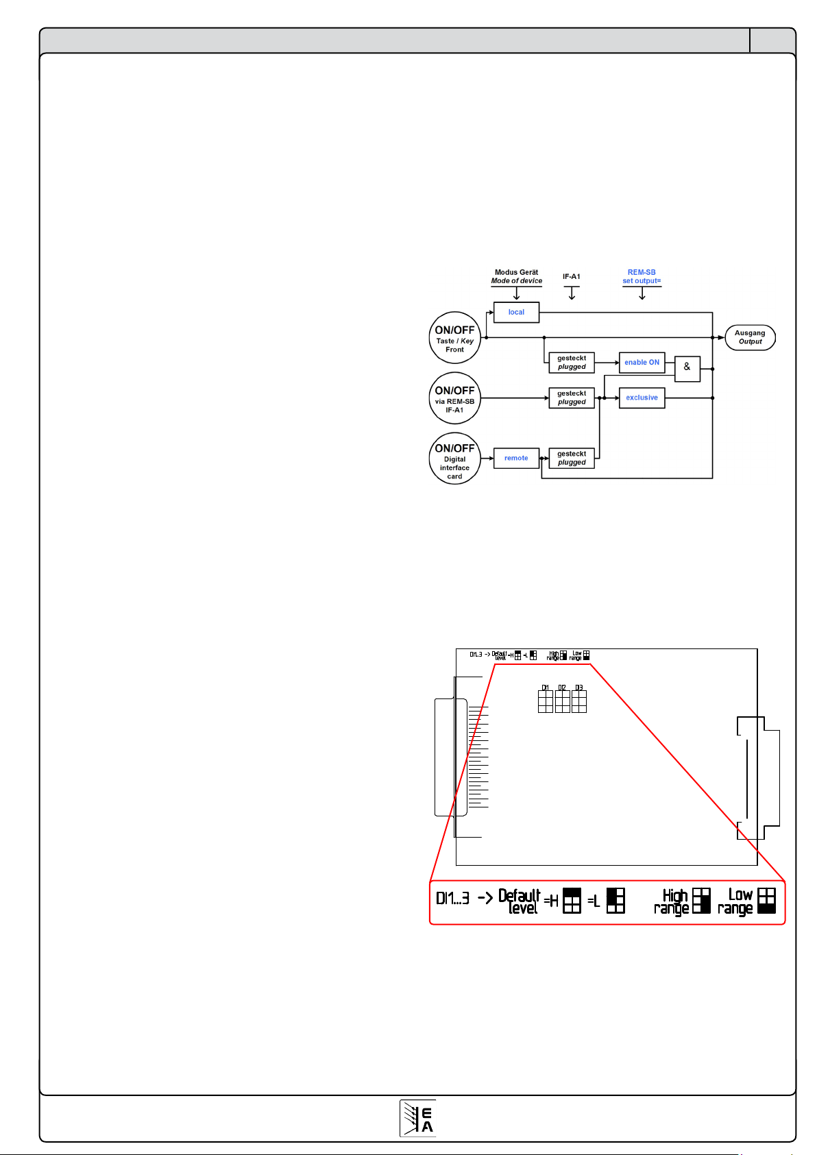
DI2/Rem-SB
Sie können hiermit den Netzgeräteausgang ein- oder
ausschalten, blockieren oder freigeben. Abhängig von der
Einstellung Set output kann durch den Eingang DI2/Rem-
SB bestimmt werden, ob der Ausgang abhängig von einer
Freigabe durch die ON/OFF-Taste oder exklusiv im „Extern-Betrieb“ (analoge Schnittstelle) bzw. „Remote-Betrieb“
(digitale Schnittstellen) ein- und ausgeschaltet werden kann.
Die Freigabe wird in der Anzeige mit auto ON (Einschalt-
bereitschaft) signalisiert. Bei exklusiver On/Off-Funktion wird
der Leistungsausgang direkt über den Eingang DI2/REMSB geschaltet. Vorsicht ist geboten, da dies nicht durch die
ON/OFF-Taste an der Front bzw. ein Befehl über eine digitale
Schnittstellebeeinußtwerdenkann(Ausnahme:Gerätist
im „Lokal-Betrieb“, dann ist der Eingang wirkungslos).
DI2/Rem-SB
Set output Grundeinstellung: enable ON
= enable ON Die Freigabe der Einschaltbereitschaft
muß mit der ON/OFF-Taste erfolgen.
= exclusive Der Netzgeräteausgang kann nur
mit dem Eingang DI2/Rem-SB (oder
mit einer digitalen Schnittstelle, falls
bestückt) ein- bzw. ausgeschaltet werden.
Bei Verwendung der Einstellung enable ON muß der Ausgang wenigstens einmal freigegeben werden. Durch die
Einstellung Power ON = restore (sieheKongurationsmenü
des Gerätes) wird der Leistungsausgang nach Netzausfall
wieder freigegeben, sofern er es vor dem Netzausfall auch
war. Er kann danach ein-/ausgeschaltet werden.
Kodierung der Eingänge DI1-3
Stecken Sie die Kurzschlußbrücken so wie in der Grafik
gezeigt, um den Eingangsspannungsbereich (siehe auch
„2. Technische Daten“) sowie den logischen Level des Einganges im nicht beschalteten Zustand festzulegen. Letzteres ist zu beachten, auch wenn die Eingänge nicht genutzt
werden, denn hiermit wird das Verhalten der Eingänge
DI1/SEL_enable und DI2/Rem-SB beeinflußt.
Default level legt den logischen Level des Einganges im
nicht beschalteten Zustand fest.
High range wählt den hohen Eingangsspannungsbereich
für den jeweiligen Eingang, bei dem „High“ einer Spannung
>9V und „Low“ einer Spannung <5V entspricht.
Low range wählt den niedrigen Eingangsspannungsbereich
für den jeweiligen Eingang, bei dem „High“ einer Spannung
>4V und „Low“ einer Spannung <1V entspricht.
Standby
Grundeinstellung: LOW
= LOW Der Eingang ist low-aktiv, Standby wird
mit einem Pegel <1V oder <5V (je nach
Kodierung) aktiviert.
= HIGH Der Eingang ist high-aktiv, Standby wird
mit einem Pegel >4V oder >9V (je nach
Kodierung) aktiviert.
Die Grafik verdeutlicht die Verkettung der diversen
Zustände bzw. Bedingungen für Lokal-, Remote- und
Extern-Betrieb in Bezug auf das Ein/Ausschalten des
Leistungsausganges:
12
© 2007, Elektro-Automatik GmbH & Co. KG
Irrtümer und Änderungen vorbehalten
DE
Über die Schnittstellenkarten
DO4/Mains OK Grundeinstellung: LOW
= { LOW | HIGH }
Wenn LOW gewählt wurde, wird der Ausgang gegen GND
geschaltet, solange Netzspannung vorhanden ist. Bei HIGH
wird er gegen 12...15V gezogen.
DO5/Standby Grundeinstellung: LOW
= { LOW | HIGH }
Wenn LOW gewählt wurde, wird der Ausgang gegen GND
geschaltet, sobald der Leistungsausgang ausgeschaltet wird
(Standby). Bei HIGH wird er gegen 12...15V gezogen.
DO6/CC Grundeinstellung: LOW
= { LOW | HIGH }
Wenn LOW gewählt wurde, wird der Ausgang gegen GND
geschaltet, sobald die Regelung des Netzteils über den
Sollwert des Stromes bestimmt wird (CC-Betrieb). Bei HIGH
wird er gegen 12...15V gezogen.
Digitale Ausgänge mit freier Funktionsbelegung
Die digitalen Ausgänge DO2, DO3, DO7, DO7 können in
ihrerFunktionsbelegungwahlweisekonguriertunddieLogik
kann invertiert werden.
DO2 Grundeinstellung: OVP LOW
DO3 Grundeinstellung: OT LOW
DO7 Grundeinstellung: CP LOW
Jedem der Ausgänge kann eine der folgenden Funktionen
zugewiesen werden:
= remote Das Netzgerät wird über eine digitale Schnitt-
stelle ferngesteuert.
= OT Übertemperatur wird gemeldet.
= CP Das Netzgerät wird über den Sollwert
der Leistung geregelt (CP-Betrieb).
= Alarm Bei einem Alarm wird das Netzteil automatisch
abgeschaltet und dies kann über einen
digitalen Ausgang ausgegeben werden.
= trip U Auslösung durch Überschreiten der Grenzen
U> und/oder U< (siehe Handbuch PSI9000).
= trip I Auslösung durch Überschreiten der Grenzen
I> und/oder I< (siehe Handbuch PSI9000).
= trip U+I Auslösung durch Überschreiten der Grenzen
U>, U<, I> und/oder I<(siehe Handbuch
PSI9000).
Festlegen des Logikpegels bei Auslösung:
= LOW Der Ausgang wird gegen GND gezogen,
sobald die ausgewählte Funktion aktiv wird.
= HIGH Der Ausgang wird über einen hochohmigen
Widerstand gegen +15V gezogen, sobald die
ausgewählte Funktion aktiv ist.
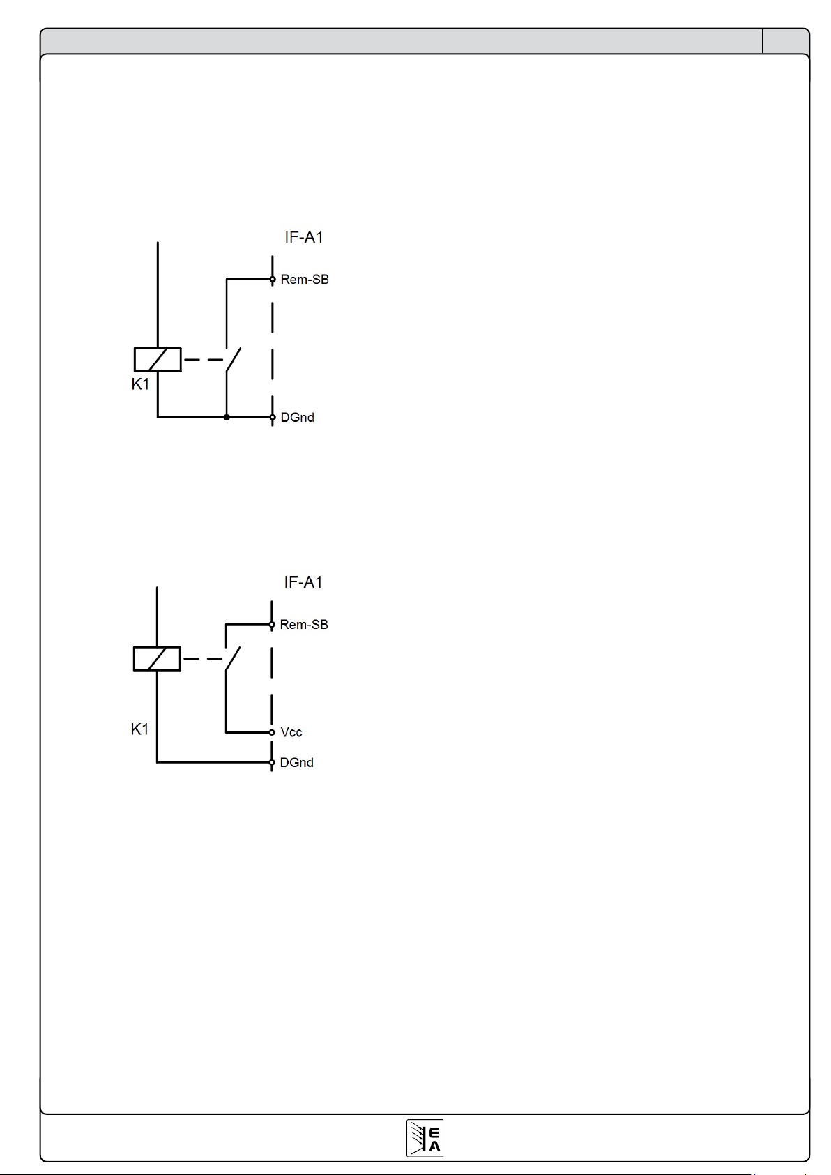
Beispiele: der Eingang DI2/Rem-SB, der das Gerät in den
Standby-Modus schaltet (Ausgang aus), kann mit Low oder
High am Eingang DI2 aktiviert werden, jenachdem, was in
der Konfiguration ausgewählt wurde.
Möglichkeit 1: der Eingang soll mit einem Relais nach GND
gezogen werden und den Geräteausgang dadurch ausschalten. Man muß also die Kodierung von DI2 auf „Default level
= H“ stecken und die Einstellung Standby = LOW, sowie Set
output = enable ON setzen.
Möglichkeit 2: der Geräteausgang soll durch eine Not-AusSchaltung abgeschaltet werden (Drahtbruchprinzip). Hierzu
muß die Kodierung von DI2 auf „Default level = L“ gesteckt,
die Einstellung im Menü auf Standby = LOW gesetzt werden.
Als Not-Aus-Schaltung dient für dieses Beispiel ein Relais
mit Schließerkontakt nach Vcc.
Es gibt natürlich noch weitere Alternativen.
Digitale Ausgänge mit fester Funktionsbelegung
Die digitalen Ausgänge DO1, DO4, DO5, DO7 können in
ihrer Funktionsbelegung nicht geändert werden. Sie können
aber den ausgegeben Logikpegel invertieren.
DO1/CV Grundeinstellung: LOW
= { LOW | HIGH }
Wenn LOW gewählt wurde, wird der Ausgang gegen GND
geschaltet, sobald die Regelung des Netzteils über den Sollwert der Spannung bestimmt wird (CV-Betrieb). Bei HIGH
wird er gegen 12...15V gezogen.
13
© 2007, Elektro-Automatik GmbH & Co. KG
Irrtümer und Änderungen vorbehalten
DE
5. Einsatz in den Geräten der Serien EL3000/EL9000
Die elektronischen Lasten der Serien EL3000 und EL9000
unterstützen folgende Schnittstellenkarten:
IF-U1, IF-R1, IF-C1
Die generelle Funktion der Schnittstellenkarten ist bei diesen
elektronischen Lasten gleich zu den Netzgeräten der Serie
PSI9000. Der Unterschied besteht nur in der Menüführung
und der Tatsache, daß von diesen Geräten ein gewisser Teil
der Netzgeräte-Funktionen nicht unterstützt wird.
Menü-Beispiel CAN-Karte:
Bei den Geräten der Serien EL3000 und EL9000 können Sie
die Schnittstellenkarten über das Setup-Menü konfigurieren.
Dieses wird aktiviert, in dem der Drehschalter Level Control
auf Setup gestellt wird
Je nach bestückter Karte (die elektronischen Lasten haben
nur einen Steckplatz) erscheint eine andere Auswahl an
Parametern. Die Parameter und deren Werte sind gleich zu
denen in Abschnitt 4.1 bis 4.3, bis auf die Ausnahme, daß
bei CAN kein Sample point eingestellt wird.
Für die USB Karte gibt es auch hier keine einstellbaren
Parameter.
Über die Schnittstellenkarten
Card found: IF-C1
CAN Baudrate: 10kBd
Card found: IF-C1
CAN Relocatable ID: 13
Card found: IF-C1
CAN Bus terminate: yes
Card found: IF-R1
RS232 Baudrate: 9600Bd
Menü-Beispiel RS232-Karte:
14
© 2007, Elektro-Automatik GmbH & Co. KG
Irrtümer und Änderungen vorbehalten
DE
6. Der System Link Mode (nur PSI9000)
Der System Link Mode unterstützt die Reihen- und Parallelschaltung. Ohne die zusätzliche Schnittstelle (SIO2) zeigt
jedes Gerät die eigenen Istwerte an, wenn die Master-SlaveReihen- oder Parallel-schaltung oder die Parallelschaltung
über den Share-Bus angewendet wird. Der Sollwert und der
Istwert müssen somit bei der Reihenschaltung mit der Anzahl
der in Reihe geschalteten Geräte multipliziert werden, da nur
der Sollwert der einzelnen Gerätes einstellbar ist. Bei der
Parallelschaltung verhält sich der Stromsollwert in Analogie
zum Spannungssollwert bei der Serienschaltung.
Über den System Link Mode werden die Istwerte zur zentralen
Bedieneinheit (Master) und die Sollwerte zu den untergeordneten Modulen (Slaves) übertragen. Die einzelnen Istwerte
und Sollwerte aller miteinander verbundenen Geräte werden
vom Master angezeigt und gestellt, so daß das Stromversorgungssystem sich wie ein Einzelgerät verhält. Desweiteren
werden einfache Meldungen, Warnungen und Alarme vom
Slave zum Master weitergegeben. Über den Master können
solche Warnungen und Alarme quittiert werden.
Die Schnittstelle unterstützt bis zu 30 miteinander verbundene Geräte. Bei der Parallelschaltung sollten nicht mehr
als zehn Geräte parallel geschaltet werden.
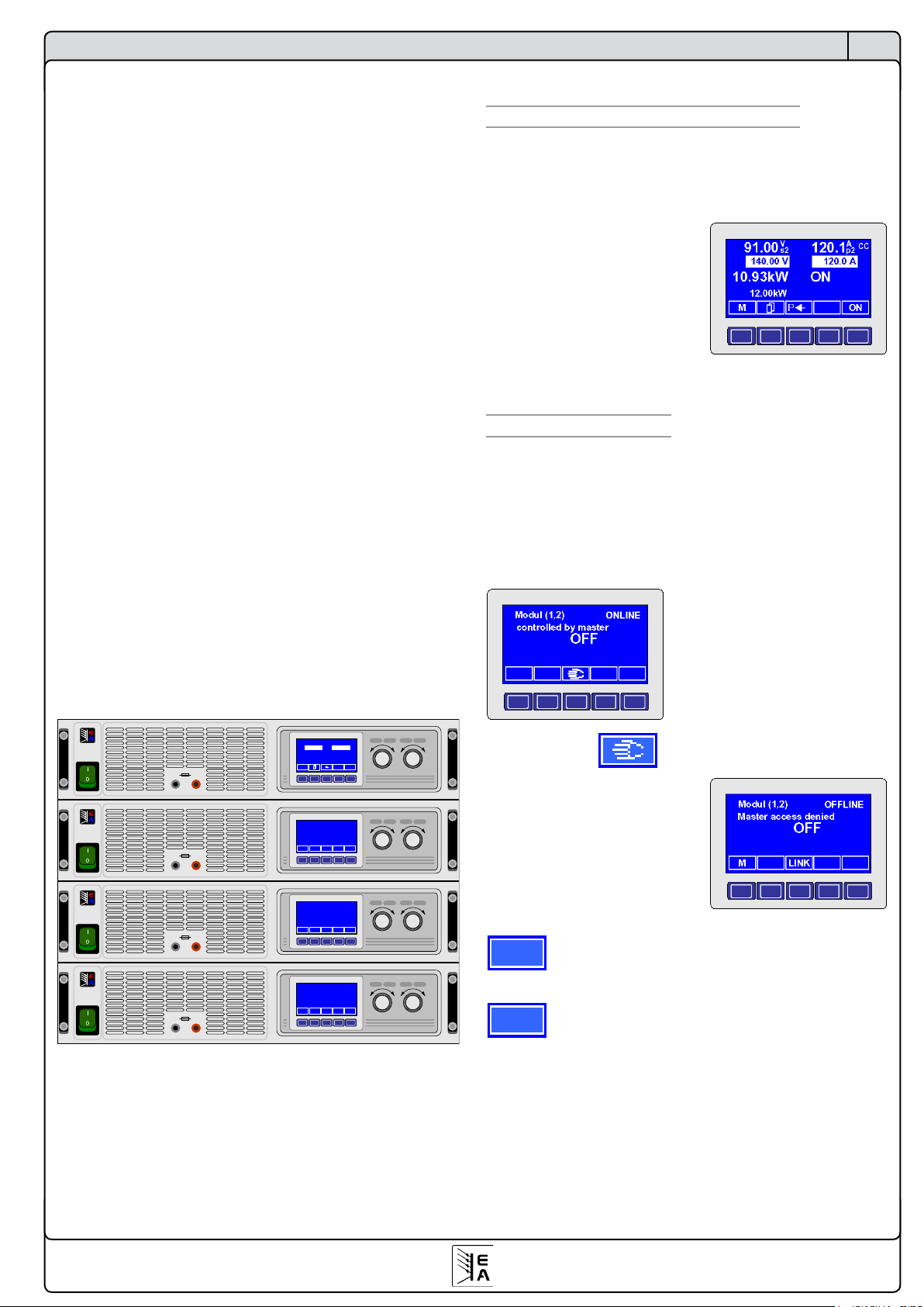
Beispiel:
Es werden vier PSI 9080-100 zusammengeschaltet. Jedes
der vier Netzteile kann 3kW Leistung liefern. Bei einer Reihenschaltung von jeweils zwei parallel geschalteten Geräten
ergibt sich eine maximale Spannung von 160 V und ein
maximaler Strom von 200 A bei einer Gesamtleistung von
maximal 12 KW.
6.1 Bedienung des System Link Mode
6.1.1 Anzeige und Bedienung des Masters
Über das Mastergerät können die Sollwerte und alle anderen
Einstellmöglichkeiten auf das gesamte Stromversorgungssystem bezogen werden. Die Anzeige des Masters zeigt die
Istwerte des Systems an.
Die Konfiguration des Masters
bestimmt das Geräteverhal-ten.
Alle Einstellwerte können wie
bei einem Einzelgerät eingestellt
werden.
Der Master stellt die in Reihe
( s2) und die parallel (p2)
geschalteten Geräte dar.
6.1.2 Anzeige der Slaves
Sofern eine Onlineverbindung mit dem Master besteht, zeigt
der Slave dies an. Jedes Gerät muß konfiguriert werden;
welches der Master ist und wie die Slaves verteilt sind, damit
der Master „weiß“, wer mit wem in Reihe und wer parallel
geschaltet ist.
Beispiel: der Slave ist online
und der Leistungsausgang des
Systems ist ausgeschaltet.
Über die Taste kann
der Slave bei ausgeschaltetem
Ausgang „offline“ gesetzt werden, ist dann also nicht mehr
mit dem Master verbunden.
Jetzt ist es möglich, die Einstellungen zur Konfiguration vorzunehmen.
M
Über die MENU-Taste wird von der Betriebsanzeige
in die Menüebene gewechselt.
LINK
Über die LINK-Taste kann der Slave wieder mit
dem Master „online“ geschaltet werden.
Über die Schnittstellenkarten
Voltage Settings Current Power
Output max. 10 A
POWER SUPPLY
EA-PSI 9080-50
0..80V/0...50A
1500W
+-
Voltage Settings Current Power
Output max. 10 A
POWER SUPPLY
EA-PSI 9080-50
0..80V/0...50A
1500W
+-
Voltage Settings Current Power
Modul (2,1)
Output max. 10 A
POWER SUPPLY
EA-PSI 9080-50
0..80V/0...50A
1500W
+-
controlled by master
ON
Voltage Settings Current Power
Output max. 10 A
POWER SUPPLY
EA-PSI 9080-50
0..80V/0...50A
1500W
+-
M ONP
91.00
140.00 V
120.1
120.0 A
10.93kW
12.00kW
ON
CC
Ap2V
s2
Modul (1,2)
controlled by master
ONLINE
ONLINE
ON
Modul (2,2)
controlled by master
ONLINE
ON
15
© 2007, Elektro-Automatik GmbH & Co. KG
Irrtümer und Änderungen vorbehalten
DE
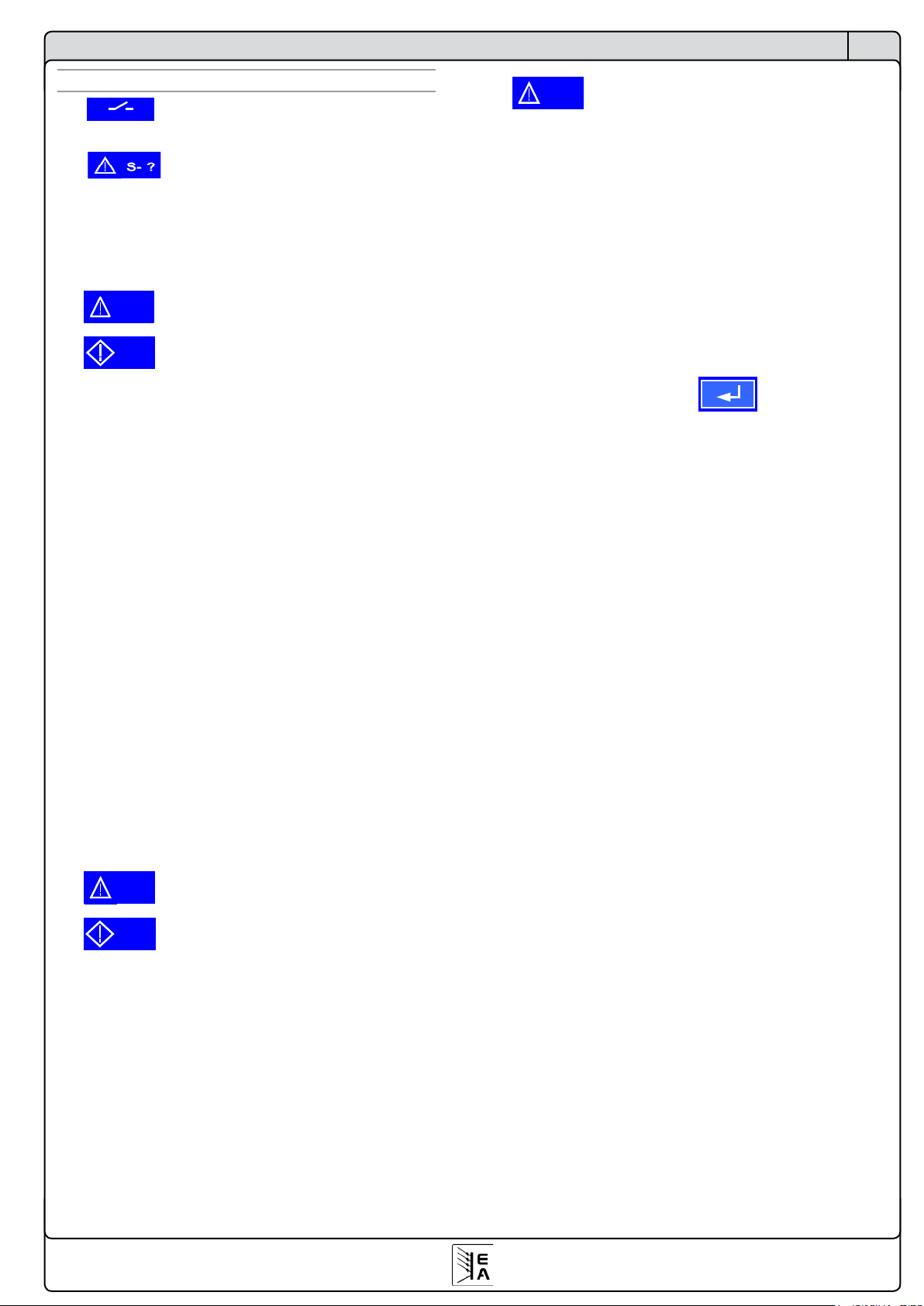
6.1.3 Spezielle Alarme, Warnungen und Meldungen
M S
Der Master meldet, dass nicht mehr alle
Slaves online sind.
Alarm vom Slave
Ein Alarm wird ausgelöst, wenn ein Slave nicht mehr
adressiert werden kann während der Master den Ausgang
eingeschaltet hatte. Zum Beispiel wenn die Verbindung
unterbrochen oder der Slave über den Netzschalter ausgeschaltet wurde.
S-PH
Ein Alarm oder
S-PH
eine Warnung mit „Auto ON“ Funktion
wird gemeldet, wenn die Verbindung zum Slave fehlt, falls
der Slave ausgeschaltet wurde oder seine Spannungs-versorgung weggefallen ist.
Ein Warnung mit „Auto ON“ Funktion schaltet den Ausgang
ab bis der Fehler behoben ist. Das Stromversorgungssystem
schaltet den Ausgang automatisch wieder ein. Der Fehler ist
zu quittieren und wird, falls er nach der Quittierung immer
noch besteht, in eine Meldung umgewandelt. Die Meldung
erlischt, sobald der Fehler behoben ist bzw. entfällt.
Ob nun ein Alarm oder eine Warnung mit „Auto ON“ ausgeführt wird, hängt von der Einstellung „Wiedereinschaltung bei
Power On“ ab (siehe Benutzerhandbuch PSI 9000, Abschnitt
„Betriebsparameter definieren“).
Power ON Grundeinstellung: OFF
= OFF Leistungsausgang bleibt nach Netzwiederkehr
oder beim Einschalten des Gerätes ausgeschaltet.
= restore Leistungsausgang schaltet sich nach Netz-
wiederkehr oder beim Einschalten des Gerätes automatisch ein, wenn er vor Wegfall
des Netz oder vor dem letzten Ausschalten
eingeschaltet war.
S-OT
Ein Alarm oder
S-OT
eine Warnung mit „Auto ON“ Funktion
wurde ausgelöst, da ein oder mehrere Slaves eine Übertemperatur ihres Leistungsteils festgestellt haben und melden.
Ob nun ein Alarm oder eine Warnung mit „Auto ON“ ausgeführt wird, hängt von der Einstellung „Wiedereinschaltung bei
Power On“ ab (siehe Benutzerhandbuch PSI 9000, Abschnitt
„Betriebsparameter definieren“).
OT disappear Grundeinstellung: auto ON
= OFF Leistungsausgang bleibt auch nach Abkühlen
des Gerätes ausgeschaltet.
= Auto ON Leistungsausgang schaltet sich nach Abküh-
len des Gerätes bzw. nach Unterschreitung
der Übertemperaturschwelle automatisch
wieder ein.
Über die Schnittstellenkarten
S-OV
Bei einem oder mehreren Slaves hat der OVP (Overvoltage
Protection) eine Alarmmeldung ausgelöst. Der Ausgang wird
abgeschaltet. Er kann erst nach Quittierung der Meldung
wieder eingeschaltet werden.
6.2 Konfiguration des System Link Mode
Um den System Link Mode nutzen zu können, müssen die
zusätzlichen Schnittstellen (SIO2) auf den IF-U1 oder IFR1-Karten miteinander, unabhängig von der Serien- oder
Parallelschaltung, über ein handelsübliches Patchkabel
CAT5 mit RJ45 Steckern verbunden. Die Endgeräte erhalten
einen Busabschluß, der über die Parameterseite eingestellt
werden muss.
Slot {A|B}: IF-R1 {IF-U1} +
SIO2 Grundeinstellung: not used
= not available
Die SIO2 Schnittstelle ist nicht verfügbar.
= not used
Die SIO2 Schnittstelle wird nicht verwendet.
= {Master|Slave}
Das Gerät wird als „Master“ oder Slave
deniert.
Die folgenden zwei Parameter sind nur sichtbar, wenn das
Gerät als Master deniertwurde.
Matrix of modules
Bei den nachfolgenden Einstellungen ist dem Master
bekannt zugeben, wieviele Geräte in Reihe und/oder
parallel liegen.
serial Grundeinstellung: 1
={1..x} Die Anzahl der in Reihe geschalteten
Geräte ist hier anzugeben.
Es gilt die maximal zulässige Isolationsspannung
zu beachten, wodurch nicht beliebig viele Geräte in
Reihe geschaltet werden dürfen!
parallel Grundeinstellung: 1
={1..30} Die Anzahl der parallel geschalteten
Geräte, unabhängig davon ob diese
direkt zum Master verbunden sind, ist hier
anzugeben.
Die zwei folgenden Parameter erscheinen nur, wenn das
Gerät als Slave definiert wurde:
Position of module
Bei den nachfolgenden Einstellungen wird die Position
des Gerätes in der Reihen- und Parallelschaltung festgelegt. Innerhalb des Stromversorgungssystems darf
eine Position nur einmal vergeben werden.
serial Grundeinstellung: 1
={1..x} Die Position innerhalb der Verschaltung
der Geräte ist anzugeben.
Es gilt die maximal zulässige Isolationsspannung
zu beachten, wodurch nicht beliebig viele Geräte in
Reihe geschaltet werden dürfen!
16
© 2007, Elektro-Automatik GmbH & Co. KG
Irrtümer und Änderungen vorbehalten
DE
parallel Grundeinstellung: 1
={1..30} Die Position innerhalb der Verschaltung
der Geräte ist anzugeben.
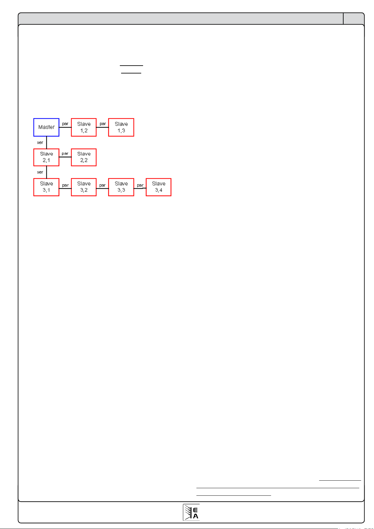
Beispiel: zum Master ist ein Gerät in Reihe geschaltet und
zu diesem Gerät noch drei weitere parallel. Diese vier parallel geschalteten Geräte müssen dann für serial den Wert
2 bekommen und für parallel aufsteigende Werte von 1...4,
wobei die 4 dem entferntesten Gerät zugewiesen wird. Siehe
auch das Bild für ein anderes Beispiel:
Achtung! Die Position serial=1/parallel=1 ist fest an den
Master vergeben. Das als Slave konfigurierte Gerät wird
diese Einstellung nicht übernehmen.
Die Schnittstelle SIO2 benötigt an den beiden Endgeräten
einen Busabschluß. Der Busabschluß kann über das Bedienmenü eingestellt werden.
bus terminate Grundeinstellung: NO
=NO Kein Busabschluß.
=YES D
ie SIO2 Schnittstelle wird abgeschlossen.
7. Die Kommunikation im Detail
7.1 Begriffserklärungen
Telegramm: Kette von Bytes, mit unterschiedlicher Länge.
Wird entweder zum Gerät gesendet oder vom Gerät empfangen.
Singlecast: Anfrage bzw. einfaches Senden an ein einzelnes Gerät. Bei in Reihe vernetzten Geräten, z.B. bei CAN,
geht das Telegramm an alle Geräte, wird aber nur von dem
adressierten Gerät akzeptiert. Betrifft nur CAN.
Broadcast: Anfrage bzw. einfaches Senden an alle Geräte.
Das heißt, alle am PC mittels der Schnittstellenkarten angeschlossenen Geräte bekommen nahezu gleichzeitig das
Telegramm. Betrifft CAN.
Multicast: wie Broadcast, aber nur an eine bestimmte Gruppe von Geräten, die durch das verschiebbare Adreßsegment
(RID) bestimmt wird. Betrifft nur CAN.
Objekt: beschreibt mit seinen Eigenschaften die Objektadresse und löst definierte Aktionen auf dem Zielgerät aus.
Nachricht (Message): Datenpaket bei CAN, wie ein Telegramm.
7.2 Vorwort
Das Kommunikationsprotokoll mit seiner objektorientierten
Telegrammstruktur ist sehr komplex. Es wird daher empfohlen, nach Möglichkeit die fertigen LabView-Bausteine
zu benutzen. Die Anwendung des Protokolls in anderen
Entwicklungsumgebungen, wie z.B. Visual Basic, C oder
.NET, erfordert Programmierkenntnisse über die Einrichtung
und Verwendung von Hardwareschnittstellen wie CAN oder
USB und das Ansprechen der entsprechenden Treiber. Hier
wird nur auf den Aufbau des Datenpakets (des Telegramms)
eingegangen und nicht darauf, wie es richtig an das Gerät
übertragen wird.
7.3 Allgemeine Hinweise zur Kommunikation
Die Firmware der verschiedenen Geräte, die mit den Schnittstellenkarten gesteuert werden sollen, ist so programmiert,
daß sie die Gegebenheiten und Probleme, die sich bei der
Ansteuerung von mehreren Geräten ergeben, so weit wie
möglich beachtet. Daher ist es nicht möglich, zu jeder Zeit
und bei jedem Zustand des Gerätes alle Objekte zu verwenden. So sind zum Beispiel die Daten für den Funktionsmanager der Serie PSI 9000 (siehe Benutzerhandbuch) nur im
Standby des Gerätes transferierbar, ansonsten kommt eine
Fehlermeldung zurück. Diese enthält einen Fehlercode, der
unter Anderem darauf hinweist, daß sich das Gerät möglicherweise nicht im Standby befindet.
7.4 Hinweise zum USB-Treiber
Der Hersteller des USB-Chips bietet für Windows 98/ME zwei
Treiber an, die auch auf der beliegenden CD im Ordner software\usb_driver\ zu finden sind. Jeweils einer ist ein reiner
USB-Treiber und der andere erstellt auf dem PC pro USBKarte einen virtuellen COM-Port (VCP-Treiber). Für Windows
XP/2003/Vista sind die zwei Treiber in einem kombiniert. Bei
Programmierung eigener Anwendungen mit LabView ist, je
nach installiertem Treiber, das USB- oder RS232-Kommunikations-VI zu verwenden. Das RSR232-VI, das mit dem
Über die Schnittstellenkarten

17
© 2007, Elektro-Automatik GmbH & Co. KG
Irrtümer und Änderungen vorbehalten
DE
VCP-Treiber zu verwenden wäre, unterstützt allerdings nur
eine USB-Karte. Die Einbindung des VCP-Treibers ist generell einfacher, dafür ist dieser Treiber anfälliger für Fehler
und Verbindungsprobleme. Außerdem wird für jedes Gerät
mit USB-Karte durch diesen Treiber ein neuer COM-Port
eingerichtet, was die Verwaltung erschwert und Plug‘n‘Play
behindert. Beim USB-Treiber ist es dagegen erforderlich,
eigene Routinen zu erstellen, die die Kommunikation mit der
USB-Hardware verwalten und den Transport der Kommunikationsdaten unseres System sicherstellen. Diese Routinen
werden von uns nicht angeboten. Beispielcode ist aber auf
der Webseite des Herstellers FTDI unter www.ftdichip.com
zu finden. Die USB-Hardware heißt FT232B.
7.5 Aufbau der Kommunikation
Die Kommunikation mit den zu steuernden Geräten basiert
auf diesen drei Telegrammformen:
a) einfache Sendung: es wird ein Objekt gesendet, das einen
Wert, z.B. Spannung, setzen soll. Sofern dies im momentanen Betriebszustand des Gerätes zulässig ist, wird das
Objekt akzeptiert und ausgeführt. Das Gerät sendet keine
Antwort. Falls die Ausführung momentan nicht zulässig ist,
kommt eine Fehlermeldung.
b) Anfrage: es wird mittels eines Objekts eine Anfrage an das
Gerät gesendet, worauf man eine Antwort erwartet. Ist die
Anfrage für den momentanen Betriebszustand des Gerätes
zulässig, wird sie ausgeführt und die Antwort gesendet, die
als Inhalt die angefragten Daten enthält. Falls nicht zulässig,
wird als Antwort eine Fehlermeldung gesendet.
c) Ereignis: ist eine Fehlermeldung, die unaufgefordert vom
Gerät gesendet wird, z.B. wenn der Zugriff auf ein Objekt
nicht möglich ist oder durch äußere Einflüsse eine Störung
der Datenkommunikation auftritt und das Gerät das Telegramm nicht erkennen kann bzw. falsch erkennt (Daten
verstümmelt). Enthält einen Fehlercode.
7.6 Telegrammaufbau IF-R1 und IF-U1
Die Schnittstellenkarten IF-R1 und IF-U1 arbeiten mit einer
gleichen, die Karte IF-C1 mit einer leicht abgewandelten
Telegrammstruktur. Lesen Sie im nächsten Abschnitt weiter,
wenn Sie eine IF-C1 Karte benutzen.
Bei der seriellen Übertragung eines Bytes über die RS232Karte werden die folgenden Bits übertragen:
Startbit + 8 Datenbits + Paritätsbit + Stoppbit
Das Parität wird auf ungerade (engl.=odd) geprüft.
Die USB-Karte arbeitet intern im Gerät mit der Übertra-
gungscharakteristik der RS232. Für beide Kartentypen sind
zur Konfiguration am jeweiligen Windowstreiber folgende
Parameter mindestens zu setzen:
Baudrate: 57600kBd
Parität: ungerade
Stoppbits: 1
Über die Schnittstellenkarten
Das Telegramm hat den folgenden Aufbau
SD+DN+OBJ+Daten+CS
und setzt sich aus diesen Bytegruppen zusammen:
Byte 0: SD (start delimiter)
Der Startdelimiter zeigt den Beginn eines Telegramms an, die
Länge der Daten, den Absender und den Telegrammtyp.
Bits 0-3
Geben die Datenlänge - 1 der Daten im Telegramm an.
Bei einer Anfrage steht hier die Länge -1 der zurücker-
warteten Daten.
Bit 4
0 = Nachricht vom Gerät an die Steuereinheit
1 = Nachricht von der Steuereinheit an das Gerät
Bits 5
0 =
Singlecast, Nachricht an einen bestimmten Empfänger
1 = Broadcast/Multicast, Rundnachricht an mehr als
einen Teilnehmer
Bits 6+7
00= reserviert
01= Anfrage von Daten
10= Antwort auf eine Anfrage
11= Daten senden (ohne vorherige Anfrage)*
* kann auch aus Richtung des Gerätes auftreten
Byte 1: DN (device node)
Über den Geräteknoten, den device node, wird das Gerät
in den Bussystemen adressiert. Ein Geräteknoten darf innerhalb eines Bussystems nur einmalig vergeben werden.
Wertebereich: 1...30, andere sind nicht gültig.
Byte 2: OBJ (object)
Die Kommunikationsobjekte eines Gerätes werden über die
hier angegebene Zahl adressiert. In der Kommunikationsobjektliste (siehe „9. Kommunikationsobjektliste“) wird die weitere Funktion oder Eigenschaft des Objekts beschrieben.
Byte 3 - 18: Daten
Der Datenbereich kann 1-16 Bytes lang sein, die Länge des
Telegramms variiert also. Bei einer Anfrage (PC -> Gerät)
werden keine Daten übermittelt, der Datenbereich entfällt
dann und ab Byte 3 folgt direkt die Checksumme, siehe
unten. Nur bei einer Antwort (Netzgerät -> PC) oder einem
Ereignis werden Daten übermittelt.
Wort x: CS (check sum)
Die Position der Prüfsumme (check sum) ist stets am Ende
des Telegramms. Die Prüfsumme wird über die einfache
Addition aller Bytes des Telegramms gebildet. Sie ist zwei
Bytes lang. Das Highbyte wird vor dem Lowbyte gesendet
(Big Endian Order).
Beispiel für ein Telegramm:
An ein Gerät mit Geräteadresse 1 soll das Objekt 71 gesendet werden (Istwerte anfragen). Das Telegramm müßte dann
so aussehen (Hexwerte):
55 01 47 00 9D

18
© 2007, Elektro-Automatik GmbH & Co. KG
Irrtümer und Änderungen vorbehalten
DE
Über die Schnittstellenkarten
Die zu erwartende Antwort könnte so aussehen:
85 01 47 64 00 1E 00 50 00 01 9F
(das ergibt 80V, 30A und 2400W bei einem Netzgerät mit
80V, 100A und 3000W, wie z.B. PSI9080-100)
Siehe auch nächsten Abschnitt für die Umrechnung der
Werte. Weitere Beispiele in Abschnitt 9.
7.6.1 Sollwerte und Istwerte umrechnen
Die Sollwerte und Istwerte (siehe Kommunikationsobjektliste) werden, mit wenigen Ausnahmen, als Prozentwert
übertragen, wobei 0x6400 = 100% entspricht. Wenn also
ein Gerät eine Nennausgangsspannung von 80V hat, dann
würde der übertragene Spannungsistwert beim Wert 0x3200
der Spannung 40V entsprechen.
Das Highbyte ist die Prozentzahl (0x64 = dezimal 100) und
das Lowbyte die Nachkommastellen der Prozentzahl. Man
muß die eingehenden Istwerte sowie die ausgehenden
Sollwerte daher umrechnen.
Nennwert d. Gerätes * Prozent-Istwert
Istwert=
25600
Beispiel: Nennwert des Gerätes ist 80V, der prozentuale Istwert kam
als 0x2454. Nach der Formel ergibt sich Istwert = (80 * 9300) / 25600 =
29,06V.
25600 * Sollwert
Prozent-Sollwert=
Nennwert d. Gerätes
Beispiel: der Sollwert soll 25,36V sein, der Nennwert d. Gerätes ist 80V.
Nach der Formel ergibt sich:
Prozent-Sollwert = (25600 * 25,36) / 80 = 8115 = 0x1FB3.
Das dezimale Ergebnis muß für die Hexzahl normal gerundet werden.
7.7 Telegrammaufbau IF-C1
Die Schnittstellenkarte IF-C1 unterstützt den CAN-Standard
2.0a. Das erweiterte Adreßformat wird nicht verwendet.
Der CAN-Treiberbaustein benötigt für eine Übertragung
den Identifier, bis zu 8 Datenbytes und die Datenlänge.
Der Identifier ist 11 Bit (CAN 2.0a) lang und wird durch den
device node, das verschiebbare Adreßsegment RID (Relo-
catable IDentifier) und den Typ der Nachricht gebildet. Für
jedes Gerät sind zwei Identifier vorgegeben (siehe auch
Abschnitt 4.3.1):
[RID*64 + device node * 2] und
[RID*64 + device node * 2 + 1],
wobei der erste Identifier nur für Objekte benutzt wird, die
Daten senden (Typ; Sendung) und der zweite (+1) für Objekte, die Daten anfragen (Typ: Anfrage).
Mit einer Nachricht (Message) können maximal 8 Bytes
übertragen werden. Das erste Byte wird belegt durch die
Adresse des Kommunikationsobjekts. Danach können bis
zu 7 Datenbytes folgen (siehe Kommunikationsobjektliste).
Um ein Objekt mit einem 16 Byte großen Datenbereich zu
schicken sind also mindestens 3 Nachrichten nötig. Siehe
auch weiter unten.
Die anzugebende Datenlänge bezieht sich nur auf das aktuell
zu sendende (oder empfangende) Telegramm. Es können
in einem CAN-Telegramm grundsätzlich nur bis zu 8 Bytes
übertragen werden. Lesen Sie dazu auch den Abschnitt über
geteilte Telegramme.
Zwei Beispiele:
a) das Gerät soll in den Remote-Betrieb gesetzt werden,
dieser ist erforderlich, um das Gerät zu steuern und Sollwerte
zu senden. Der device node wurde am Gerät auf 15 und die
RID auf 3 gesetzt. Da nur gesendet wird, ist der Nachrich-
tentyp Sendung. Es ergibt sich ein Identifier von 3 * 64 +
15 * 2 = 222d oder 0xDE, laut obenstehender Formel. Nach
der Objektliste im Abschnitt 9 wird das Objekt 54 (hex: 0x36)
mit den Datenbytes 0x10 (Maske) und 0x10 (set remote)
benötigt. Die sich ergebende Datenlänge ist 3. Somit sieht
die CAN-Nachricht so aus:
ID DL DATEN
DE 03 36 10 10
Wollte man den Zustand des Gerätes nicht setzen, sondern
abfragen, so wird laut der obigen Formel hier nun der Identifier 0xDF verwendet und zwecks einer Anfrage reicht die
Objektnummer allein als Datum aus. Die sich ergebende
CAN-Nachricht für die Abfrage des Gerätezustands sieht
dann so aus:
ID DL DATEN
DF 01 36
7.7.1 Geteilte Telegramme
Bei einem geteilten Telegramm, d.h. einem Telegramm,
das sich aus mehreren Nachrichten zusammensetzt (nur
möglich bei Objekten im „String“-Format), wird nach der
Objektadresse eine weitere Kennung eingefügt. Die Kennung der ersten Nachricht ist 0xFF, der zweiten Nachricht ist
0xFE und die dritte Nachricht ist 0xFD. Diese Kennung hilft
dabei, diese Telegramme als aufgeteilt zu identifizieren und
deren Dateninhalt nach Empfang wieder richtig zusammen
zu setzen. Die Reihenfolge der Nachrichten ist nicht fest
vorgegeben. Bei Verwendung der Gateway-Funktion (nur
PSI9000) werden die geteilten Telegramme nicht vom Gateway zusammengesetzt. Dies muss in der übergeordneten
Steuereinheit geschehen.
7.7.2 Timing von Telegrammen
Singlecast :
Nach jeder Anfrage benötigt das Gerät typisch 5ms und
maximal 50ms für eine Antwort. Grundsätzlich darf unmittelbar nach der Antwort wieder gesendet werden. Nach dem
Empfangen eines Ereignisses (Antworten ohne Anfrage)
muss mindestens 50 ms gewartet werden. Empfohlen wird
eine Zeit von 100 ms, damit das Gerät nicht zu sehr durch
die Kommunikation ausgebremst wird.
Bei der Gateway-Funktion (nur PSI9000) muß zudem die
Übermittlung der Telegramme von einem Bussystem auf das
andere Bussystem berücksichtigt werden. Hier kann sich die
Antwort bis zu 200 ms verzögern.
Nach dem Empfangen einer Fehlermeldung sollte mindestens 100ms gewartet werden.

19
© 2007, Elektro-Automatik GmbH & Co. KG
Irrtümer und Änderungen vorbehalten
DE
Über die Schnittstellenkarten
Broadcast:
Nach jeder Rundumanfrage können die Busteilnehmer nur
nacheinander antworten. Abhängig vom Bussystem, der
Baudrate und der Anzahl der angesprochenen Busteilnehmer, sowie dem zusätzlichen anderen Datenverkehr wird
sich die Antwort mehr oder weniger verzögern. Da die Zeit
nur individuell zu spezifizieren ist, kann sie in erster Annäherung mit Busteilnehmeranzahl * Antwortzeit beim Single-
cast angenommen werden. In den meisten Fällen wird die
Antwortzeit aber wesentlich kürzer sein.
8. Hilfsmittel für die Kommunikation
8.1 Übersicht Labview VIs
Zur Integration der Geräten in eigene Labview-Applikationen
werden mehrere Labview VIs zur Verfügung gestellt.
Mit den virtuellen Instrumenten (VI) ist eine einfache Einbindung und Programmierung einer Anwendung möglich,
ohne dass der Anwender sich in die unteren Ebenen der
Kommunikation einarbeiten muß. Sie erleichterten das
Einfügen in bestehende Anwendungen oder die Erstellung
eines anwenderspezifischen Programms.
Um die Funktionen der VIs nutzen zu können, wird die Softwareentwicklungsumgebung Labview der Firma National
Instruments benötigt. Die bereitgestellten Labview VIs sind
kompatibel mit der Version ab 6.1.
Folgende minimale Systemvoraussetzungen sollten erfüllt
sein:
- Pentium 3 Prozessor mit 256 MB Hauptspeicher
- Windows Betriebssystem (Win98 oder WinXP)
Updates können über die Webseite www.elektroautomatik.
de heruntergeladen werden, sofern verfügbar.
Um die Labview VIs in Ihre Umgebung einzubinden lesen
Sie bitte die Installationshinweise in der Datei „installation_deutsch.pdf“ auf der beiliegenden CD.
Nach der Installation finden Sie die VIs in LabView normalerweise im Kontextmenü unter „Instrumenten-I/O -> Instrumententreiber -> EA“.
Es gibt VIs, die nur für Geräte der Serie PSI9000 gedacht
sind und auch nur mit diesen funktionieren. Diese haben
das Kürzel PSI9 vor dem Namen und auch im VI-Icon. Dann
gibt es welche nur für die elektronische Lasten der Serien
EL3000 und EL9000. Diese haben das Kürzel EL vor dem
Namen und auch im VI-Icon. Weitere VIs ohne besonderes
Kürzel sind gemeinsam nutzbar. Funktion und Benutzung
sind im Handbuch zu den VIs beschrieben, Dieses rufen
Sie wie gewohnt über die LabViewHilfe auf oder direkt aus
dem Ordner \software\labview auf der CD. Je nach Windowsversion kann es, auf Grund von Sicherheitseinstellungen
des Internetexplorers, nötig sein, die Datei vor dem Öffnen
auf die Festplatte zu kopieren, damit Sie den Inhalt sehen
können.
Die VIs werden in drei Kategorien unterteilt:
1. Kommunikation-VIs
2. Standard-VIs
3. Spezial-VIs
Wichtig! Bitte verwenden Sie stets die richtigen VIs für
Ihr Gerät
Lesen Sie auch die LabView VIs Hilfedatei auf der beiliegenden CD, um einen Überblick über die Handhabung
der VIs zu bekommen.

20
© 2007, Elektro-Automatik GmbH & Co. KG
Irrtümer und Änderungen vorbehalten
DE
LabView-Unterstützung
8.1.1 Kurzinfo Kommunikations-VIs
Die Kommunikations-VIs dienen als Schnittstellentreiber für
die unterschiedlichen Bussysteme. Diese VIs sind die Basis
der Standard-VIs. Ohne eine im Hintergrund laufende Kommunikation können die Geräte nicht angesprochen werden.
Daher müssen diese VIs zwangsweise in der Applikation
verwendet werden und zwar vor der Benutzung eines der
anderen VIs. Für jede verwendete Schnittstelle gibt es ein
eigenes VI. Hier nur eine Übersicht der VIs, eine genauere
Beschreibung aller VIs befindet sich in der LabView Hilfedatei
zu den VIs, die sich auf der CD befindet.
- CAN.vi
Lesen/Schreiben von Kommunikationsobjekten über das
CAN-Protokoll und IF-C1.
- RS232.vi
Lesen/Schreiben von Kommunikationsobjekten über RS232
(COM-Port) und IF-R1.
- USB.vi
Lesen/Schreiben von Kommunikationsobjekten über das
USB und IF-U1
- Communication_layer.vi
Kernanwendung der Kommunikation, benutzt die anderen
drei VIs wahlweise einzeln oder zusammen.
Bei den VIs „RS232“ und „USB“ können bis zu 29 weitere
Netzteile gesteuert werden, falls das angesprochene Gerät als Gateway zum CAN-Bus parametriert wurde (siehe
„4.3 CAN-Karte IF-C1“). Die Gateway-Funktion ist nur bei
geringem Datenverkehr über den CAN-Bus empfehlenswert, denn die Kommunikation direkt über den CAN-Bus
ist leistungfähiger. Dazu wird allerdings eine CAN-Karte im
PC benötigt.
8.1.2 Kurzinfo Standard VIs
Die Standard VIs beinhalten die am häufigsten verwendeten
VIs, die Werte im Gerät setzen bzw. aus dem Gerät lesen.
Sie können beliebig oft eingesetzt werden und dürfen nur
dann parallel ausgeführt werden, wenn mehrere Geräte
angesprochen werden. Diese VIs bauen auf die Kommunikations-VIs auf, sind also davon abhängig, daß mindestens
eines davon, je nach verwendeter Karte, im Hintergrund
richtig läuft.
Hier nur eine Übersicht der wichtigsten VIs, eine genauere
Beschreibung aller VIs befindet sich im Handbuch zu den
EA LabView VIs.
- init.vi
Wird nur einmal beim Start der Applikation verwendet (wenn
die Kommunikation bereits läuft) und initialisiert die angeschlossenen Geräte in dem es feststellt, welche und wieviele
Geräte angeschlossen sind. Weiterhin werden benötigte
Werte und Daten aus den Geräten gelesen und intern an
die anderen VIs weitergegeben.
- set_mode.vi
Setzt den Modus des Gerätes in Bezug auf die externe
Steuerung. Es gibt zwei Zustände, „Standby“ und „Remo-
te“. Standby schaltet den Leistungsaus- bzw. eingang des
Gerätes ein/aus. „Remote“ setzt das Gerät in den Fernsteu-
er-Modus. Nur wenn dieser aktiviert wurde, kann das Gerät
gesteuert werden. Ohne können nur Anfragen gesendet
werden, wie z.B. Istwerte auslesen.
Der Fernsteuer-Modus kann jedoch nur aktiviert werden,
wenn das Gerät im Normalmodus arbeitet, sprich nicht „lokal“ gesetzt wurde, oder durch einen anderen, besonderen
Zustand blockiert wird.
- wr_set_values.vi
Setzt die Sollwerte für U/I/P/R, je nach Art des Gerätes kann
die Anzahl der setzbaren Sollwerte variieren. Erfordert den
Fernsteuer-Modus. Es werden nicht alle Werte auf einmal
übertragen, sondern es wird pro Sollwert ein Telegramm
gesendet. Wenn ein Sollwert nicht gesendet werden soll,
muß das Senden einfach mit einem zugehören „Enable“Bit deaktiviert werden. Die Grenzen für die einzugebenden
Werte sind automatisch mit der Initialisierung (init.vi) gesetzt, zu hohe Werte werden auf den maximalen Nennwert
gesetzt. Dies ist ein einfaches Senden, das keine Antwort
generiert.
- actual_values.vi
Fragt die Istwerte des Gerätes ab. Je nach Gerätetyp er-
gibt sich eine unterschiedliche Anzahl von Istwerten, deren
Wertigkeit innerhalb der Gerätenennwerte liegen muss.
Diese Istwerte sollten stets mit denen am Gerät gezeigten
übereinstimmen.

21
© 2007, Elektro-Automatik GmbH & Co. KG
Irrtümer und Änderungen vorbehalten
DE
Programmierung
9. Anleitung zur Programmierung der Schnittstellenkarten
9.1 Erläuterungen zur Kommunikationsob-
jektliste
Im Abschnitt 9.3 befindet die Kommunikationsobjektliste.
Diese Liste ist die Referenz für die Erstellung eigener Applikationen abseits von LabView, die die genannten Geräte
steuern sollen.
Die 1. Spalte ist die Objektnummer (=Objektadresse, dezimal). Diese Nummer muss im Telegramm dem Byte OBJ
zugewiesen werden.
Die 3. Spalte gibt Auskunft darüber, ob das Objekt nur gelesen oder sowohl geschrieben als auch gelesen werden
kann.
Die 4. Spalte beschreibt eine besondere Zugriffsbedingung
für ein Objekt. Die Ausführung des Objekts ist zusaätzlich
von einer der unten genannten Voraussetzungen abhängig.
Ist diese nicht gegeben, wird das Objekt nicht ausgeführt und
das Gerät sendet als Antwort eine Fehlermeldung, die einen
Fehlercode enthält. Bedeutung der Bedingungswerte:
1 =
Der Ausgang/Eingang des Gerätes muß abgeschaltet sein
(Objekt wird nur vom Gerät akzeptiert, wenn der Leistungsausgang/eingang
auf OFF steht)
2 = Option „Innenwiderstand“ muß freigeschaltet sein*
(Objekt wird nur vom Gerät akzeptiert, wenn die Option Innenwiderstandsregelung freigeschaltet ist)
3 = Übertragung des Funktionsablaufs ist freigeschaltet*
(Objekt wird nur vom Gerät akzeptiert, wenn es vorher durch ein anderes
Objekt angewiesen wurde, daß Daten für den Funktionsmanager gesetzt
werden sollen)
4 = Funktionsmanager aktiviert*
(Objekt wird nur vom Gerät akzeptiert, wenn der Funktionsmanager aktiv
ist, sprich am Gerät über das Menü oder über ein anderes Objekt aufgerufen wurde)
5 = Funktionsmanager nicht aktiviert*
(Objekt wird nur vom Gerät akzeptiert, wenn der Funktionsmanager nicht
aktiviert ist)
* nur bei Serie PSI 9000
Achtung! Es ist generell erforderlich das Gerät vor
dem Senden von Objekten, die Werte im Gerät ändern,
in den Remote-Zustand zu setzen.
Die 5. Spalte gibt den Typ der Daten im Telegrammteil
Daten an.
Die 6.Spalte gibt die Datenlänge des Telegrammteils Daten
an. Bei Objekten mit dem Datentyp „string“ bezieht sich die
Angabe auf die maximal mögliche Länge. Der String muß
entweder mit „EOL“ (end of line ) = 0 abgeschlossen werden
oder endet nach der Übertragung der maximal angegebenen Bytes. Strings werden bei CAN in bis zu drei geteilten
Nachrichten übertragen. Siehe auch „7.5.2 Telegrammaufbau IF-C1“.
Die 7.Spalte wird zur Maskierung von Daten des Typs „char“
verwendet. Die Maske (1. Datenbyte) gibt an, welche Bits
überschrieben werden können. Die Maske ist erforderlich,
damit eben nur die Bits verändert werden, die man verändern
möchte. Das 2. Datenbyte gibt an, welche Bits geändert
werden sollen.
Die 8. + 9. Spalte erläutern genauer die einzelnen Informa-
tionen im Telegrammteil Daten.
DasZeitformatdeniertsichso:
0 ... 10000 = 0…10,000s
16384 ... 22383 = 10,00s...59,99s
32768 …36367 = 1min:00s…59,99min
49152 …55151 = 1h:00min…99h:59min
9.2 Vorgehensweise
Das Programmieren der unterschiedlichen Geräte, in denen
die Schnittstellenkarten verwendet werden, erfolgt stets nach
dem gleichen Schema, wenngleich sich Anzahl und Funktion
der Kommunikationsobjekte unterscheiden.
Generell gilt:
- Überwachung (Monitoring), also reine Abfrage von Istwerten und Status, ist mittels der entsprechenden Objekte
(Zugriffart ‚read‘) immer möglich, die Geräte benötigen
dazu keinen Remote-Modus
- Setzen von Zuständen und Sollwerten (Controlling)
erfordert die Aktivierung des Remote-Modus (remote =
ferngesteuert durch eine digitale Schnittstelle)
- der Remote-Modus kann durch bestimmte Umstände blokkiert werden, z. B. expliziter Lokalbetrieb (nur PSI9000)
oder wenn sich ein Gerät in einer Betriebsart befindet, die
keinen Remote-Modus zuläßt bzw. eine derartige Anfrage
ignoriert. Näheres dazu entnehmen Sie bitte der Bedienungsanleitung Ihres Gerätes.
Um ein Gerät zu steuern, sprich z. B. einen Sollwert zu
senden müssen Sie
1. den Remote-Modus aktivieren (Objekt 54)
2. den Sollwert senden
Der Remote-Modus sollte verlassen werden, wenn er nicht
mehr benötigt wird. Solange er aber aktiviert ist, kann das
Gerät nicht oder nur bedingt manuell bedient werden. Der
Modus wird in der Anzeige des Gerätes angezeigt.
Beispiel 1: Remote-Modus aktivieren über IF-R1/IF-U1
Nach der Vorgabe des Telegrammformats (siehe auch 7.5)
ist das erste Byte der Startdelimiter, der von der Richtung
des Telegramms und dem Anfragetyp abhängig ist. Bei einer
Geräteadresse von z. B. 5 ergibt sich ein SD von 0xD2, in
Bits zerlegt sieht das so aus:
11 01 00 10
Bits 0...3: 2 = es werden 3 Bytes gesendet
Bit 4: 1 = vom PC gesendet
Bit 5: 0 = Singlecast
Bit 6+7: 11 = Daten senden
weiter...
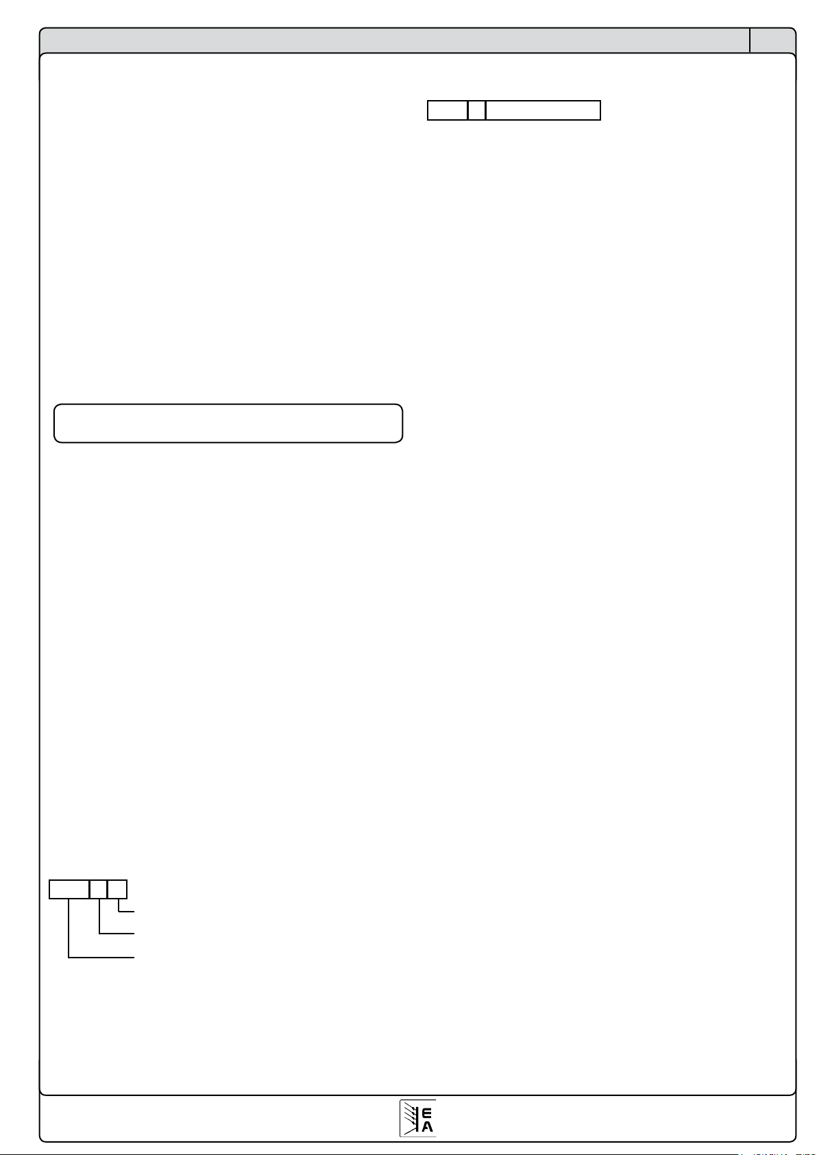
22
© 2007, Elektro-Automatik GmbH & Co. KG
Irrtümer und Änderungen vorbehalten
DE
Programmierung
Alternativ zum bitweisen Zusammensetzen kann man sich
das vereinfachen, indem man Hexwerte addiert. Ausgehend
von Bit 6+7 ergibt sich folgendes:
SD = Sendungstyp + Castform + Richtung + Datenlänge
wobei Sendungstyp entweder
0xC0 Daten senden oder
0x40 Anfrage
und Castform entweder
0x00 Singlecast oder
0x20 Broadcast
und Richtung entweder
0x10 vom PC ans Gerät oder
0x00 vom Gerät an den PC
und die Datenlänge - 1 von
0x00...0x0F bis zu 16 Bytes am Stück (bei CAN siehe
„7.6.1 Geteilte Telegramme“).
Die Datenlänge entspricht der Anzahl der gesendeten
Bytes -1!! Immer beachten!!
Die Geräteadresse des anzusprechenden Gerätes ist 5,
das zu benutzende Objekt 54 als Hexwert 0x36, die Maske
für den Remote-Modus (siehe auch Tabelle in 9.3) ist 0x10
und das Steuerbyte für Remote auch 0x10. Somit ergibt sich
dieses Telegramm:
D1 05 36 10 10 01 2C
Zum Umkehren des Ganzen, also der Deaktivierung, ist dann
D1 05 36 10 00 01 1C zu senden. Die Maske bleibt natürlich
gleich, nur das Steuerbyte ändert sich.
Beispiel 2: Istwerte abfragen über CAN
Bei CAN entfallen der Startdelimiter SD und die Checksumme CS, somit benötigen wir nur das Objekt, laut Tabelle 71
(hex = 0x47), den Identifier ID (Berechnungsbeispiel siehe
Abschnitt 7.6) und die Länge der gesendeten Bytes. Bei der
CAN-Nachricht zählt das Objekt zur Datenlänge, daher ergibt
sich hier eine Datenlänge von 1, weil hier nur das Objekt zur
Anfrage der Istwerte gesendet wird. Geräteadresse (device
node) auch hier 5, der RID sei mal auf 8 gesetzt. Gemäß
der Formel aus Abschnitt 7.6 ergibt sich ein Identifier von 8
* 64 + 5 * 2 +1 = 523 (hex = 0x20B). Die +1 deshalb, weil
es eine Anfrage ist. Wir schicken also an ID 0x20B ein Byte.
Die CAN-Nachricht so dann so aus:
02 0B 01 47
Objekt 71 (0x47), Anfrage Istwert
Datenlänge = 1
Identifier
Achtung! Das ist nicht die Byte/Bitaufteilung, die über
den CAN-Bus übertragen wird. Ein CAN-Controller fügt,
je nach Betriebsart, diverse Steuerbits in die Nachricht
ein und hängt an das Ende eine Checksumme. Dies
zeigt nur das, was man als User an den CAN-Controller
schicken müßte.
Eine mögliche Antwort auf diese Anfrage könnte so aussehen:
02 0B 06 64 00 0A 00 42 42
Gleicher Identifier, Datenlänge ist 6, weil immer drei 16-BitIstwerte übertragen werden. Die Istwerte werden als Prozentzahlen übertragen und müssen entsprechend des Typs
des Gerätes zurückgerechnet werden. Siehe dafür Abschnitt
„7.5.1 Werte umrechnen“. Für eine EL9080-200 ergäben sich
hier 100% für Spannung (=80V), 10% für Strom (=20A) und
66,66% für die Leistung (=1600W).
Die Gerätenennwerte, also Nennstrom, Nennleistung und
Nennspannung, können mit entsprechenden Objekten aus
dem Gerät gelesen werden und zur Umrechnung benutzt
werden.

23
© 2007, Elektro-Automatik GmbH & Co. KG
Irrtümer und Änderungen vorbehalten
DE
9.3 Kommunikationsobjektliste
9.3.1 Für Geräte der Serie PSI9000
Übersichten
1 2 3 4 5 6 7 8 9
Objekt / Object
Beschreibung / Description
Zugriff /
Access
Zugriffsbedingung /
Access condition
Datentyp / Data type
Datenlänge /
Data length in Bytes
Maske bei Typ 'char'
/ Mask for type 'char'
Beispiel oder weitere Erkärung / Example or further description
0 Gerätetyp / Device type read only --- string 16 PSI 9080-050+EOL (EOL= End of Line)
1 Geräteseriennummer / Device serial no. read only --- string 16 2006100001+EOL
2 Gerätenennspannung / Nominal voltage read only --- float 4 Unenn / Unom= 80.0 (Floating point number IEEE754 Standard)
3 Gerätenennstrom / Nominal current read only --- float 4 Inenn / Inom= 50.0 (Floating point number IEEE754 Standard)
4 Gerätenennleistung / Nominal power read only --- float 4 Pnenn / Pnom=1500.0 (Floating point number IEEE754 Standard)
5 Max. Innenwiderstand / Max. internal resistance read only --- float 4 Rnenn /Rnom=16.00 (Floating point number IEEE754 Standard)
6 Artikelnummer / Order no. read only --- string 16 15200768+EOL
7 Benutzertext / User text read/write --- string 16 Max. 15 alphanumerische Zeichen / Max. 15 characters +EOL
8 Hersteller / Manufacturer read only --- string 16 EA-VIERSEN +EOL
9 Softwareversion / Software version read only --- string 16 V2.01 09.08.06 +EOL
10 Kartentyp / Interface type Slot A read only --- string 16 IF-R1
11 Seriennummer / Serial no. Slot A read only --- string 16 200610002+EOL
12 Artikelnummer / Order no. Slot A read only --- string 16 33100213+EOL
13 Softwareversion / Software version Slot A read only --- string 16 EOL
14 Kartentyp / Interface type Slot B read only --- string 16 IF-C1
15 Seriennummer / Serial no. Slot B read only --- string 16 200610003+EOL
16 Artikelnummer / Order no. Slot B read only --- string 16 33100214+EOL
17 Softwareversion/ Software version Slot B read only --- string 16 V2.01 09.08.06 +EOL
18 2. Softwareversion / 2nd software version read only --- string 16 EOL
19 Geräteklasse / Device class read only --- integer 2 1 = PSI9000; 2 = EL3000 / 9000
20 Speichern von Profilen / Save and load of profiles read/write 1 char 2 0x37
Bit 0..4:
:
Bit 5:
Bit 6:
Bit 7:
Auswahl der Profilnummern / Select profile no.
0 = default; 1 = Profile 1; 2 = Profile 2; 3 = Profile 3; 4 = Profile 4
Lade gewähltes Profil / Load selected profile (1...4)
Speichern des akt. Profils nach Platz x / Save current profile to memory x
Vorgang noch nicht beendet / Profile load/save are busy
21 Freigabe Sollwertsatz / Enable preset list no. read/write 1 char 2 0x0F
Bit 0:
Bit 1:
Bit 2:
Bit 3:
Sollwertsatz 1 ist freigegeben / Preset list no. 1 is enabled Sollwertsatz 2
ist freigegeben / Preset list no. 2 is enabled Sollwertsatz 3 ist
freigegeben / Preset list no. 3 is enabled Sollwertsatz 4 ist freigegeben /
Preset list no. 4 is enabled
22 Sollwertsatz [0] / Preset list [0] U+I read/write 1 integer 4
23 Sollwertsatz [1] / Preset list [1] U+I read/write 1 integer 4
24 Sollwertsatz [2] / Preset list [1] U+I read/write 1 integer 4
25 Sollwertsatz [3] / Preset list [1] U+I read/write 1 integer 4
26 Sollwertsatz [0] / Preset list [0] P+R read/write 1 integer 4
27 Sollwertsatz [1] / Preset list [1] P+R read/write 1 integer 4
28 Sollwertsatz [2] / Preset list [1] P+R read/write 1 integer 4
29 Sollwertsatz [3] / Preset list [1] P+R read/write 1 integer 4
30 Max. einstellbare Spg. / Max. adjustable voltage read/write 1 integer 2 Spannungsgrenze (% von Unenn* 256) / Voltage limit (% of Unom* 256)
31 Min. einstellbare Spg. / Min. adjustable voltage read/write 1 integer 2 Spannungsgrenze (% von Unenn* 256) / Voltage limit (% of Unom* 256)
32 Max. einstellbarer Strom / Max. adjustable current read/write 1 integer 2 Stromgrenze (% von Inenn* 256) / Current limit (% of Inom*256)
33 Min. einstellbarer Strom / Min. adjustable current read/write 1 integer 2 Stromgrenze (% von Inenn* 256) / Current limit (% of Inom*256)
34 Max. einstellbare Leistung / Max. adjustable power read/write 1 integer 2 Leistungsgrenze (% von Pnenn*256) / Power limit (% of Pnom *256)
35 Max. einstellb. Widerstand/ Max. adj. resistance read/write 1+2 integer 2 Innenwiderstandsgrenze(% von Rnenn *256) / Resistance limit (% of Rnom *256)
36 Profileinstellungen / Profile settings read/write 1 char 2 0xDF
Bit 0+1:
:
Bit 3 :
:
Bit 4:
:
Bit 6+7:
:
:
Betriebsart / Set operation mode
00 = U/I/P mode 01 = U/I/R
Übertemperaturabschaltung / Reaction after overtemperature
0= OT Alarm disappear: OFF; 1= OT Alarm disappear: Auto ON
Netzwiederkehr / Reaction after power-on
0= Power ON: OFF , 1= Power ON = auto ON
Einstellvarianten von Sollwerten / Mode for set values
00 = direct adjust of set value; 01 = adjust set value with return
10 = set value via preset list
37
38 OVP Grenze / OVP threshold read/write 1 integer 2 Spannungswert (% von Unenn* 256) / Voltage value (% of Unom* 256)
39 Überspannungsgrenze +Zeit / U> threshold +time read/write 1 integer 4
40 Unterspannungsgrenze + Zeit / U< threshold +time read/write 1 integer 4
41
42 Überstromgrenze +Zeit / I> threshold +time read/write 1 integer 4
43 Unterstromgrenze+Zeit / I< threshold +time read/write 1 integer 4
44 Überwachung U / Supervise U settings read/write 1 char 2 0x33
Bit 1+2: U>
Bit 4+5: U<
00=keine / none; 01= nur Anzeige / indicate only
10=Warnung / Warning; 11 = Alarm
45 Überwachung I / Supervise I settings read/write 1 char 2 0x33
Bit 1+2: I>
Bit 4+5: I<
00=keine / none; 01= nur Anzeige / indicate only
10=Warnung / Warning; 11 = Alarm
46 Überwachung Soll-Istvergleich/ Supervise step resp. settings read/write 1 char 2 0x33
Bit 1+2:
:
Bit 4+5:
00=keine / none; 01= nur Anzeige / indicate only
10=Warnung / Warning; 11 = Alarm
00=dU; 01=di; 10= dP
47
Soll-Istvergleich Toleranz+Zeit / Set-act. comparison tolerance
+ time
read/write 1 integer 6
Word 0:
Word 1: Tsr
Word 2: Tsf
Toleranz (% von Nennwert* 256) / Tolerance ( % of nom. value* 256)
Zeit / Time (siehe Zeitformat/ see format of time values)
Zeit / Time (siehe Zeitformat/ see format of time values)
48
49
50 Sollwert U / Set value U read/write --- integer 2 Spannungswert (% von Unenn* 256) / Voltage value (% of Unom* 256)
51 Sollwert I / Set value I read/write --- integer 2 Stromwert (% von Inenn* 256)/ Current value (% of Inom*256)
52 Sollwert P / Set value P read/write --- integer 2 Leistungsangabe (% von Pnenn*256) / Power value (% of Pnom *256)
53
Sollwert R / Set value R **** EL_MMI: Sollwert A für R1
Bereich / Set value A for R1 range
read/write 2 integer 2 Innenwiderstand (% von Rnenn *256) / Resistance (% of Rnom *256)
54 Steuerung des Netzteils / Power supply control read/write --- char 2 0x51
Bit 0:
Bit 3:
Bit 4:
Bit 6:
Netzteilausgang eingeschaltet / Output is switched on
Pmax reduziert bei Netzunterspg. / P reduced at mains undervoltage
Setzt in Fernbetriebmodus / Sets into remote state
Funktionsmanager in Betrieb/ Function manager active
55
56 Steuerung des Funktionsman. / Control of function manager read/write 4 char 2 0xFF
Bit 0: ESC
Bit 0: NEW
Bit 1: STEP
Bit 3: STOP
Bit 4: RUN+GO
Ext. Bedienung des Funktionsman. / External control of the function man.
Verlasse Funktiosmanager / Leave function manager mode
Setzt den Fkt.-gen.auf den Startpunkt zurück / Reset fct. man. to start
Führt den nächsten Seq.punkt aus / Proceed to the next seq.-point
Hält den laufenden Fkt.man. an/ Halt the function manager
Startet den Funktionsmanager / Start the function manager
Word 0:
Word 1:
Word 0:
Word 1:
Leistungssollwert (% von Pnenn*256) / Set power (% of Pnom *256)
Innenwiderstand(% von Rnenn *256) / Set resistance (% of Rnom *256)
Word 0:
Word 1:
Word 0:
Word 1:
Spgs.-Sollwert (% von Unenn* 256) / Set voltage ( % of Unom* 256)
Stromsollwert (% von Inenn* 256) / Set current (% of Inom*256)
Spannungswert (% von Unenn* 256) / Voltage value (% of Unom* 256)
Zeit / Time (siehe Zeitformat / see format of time values)
Stromwert (% von Inenn* 256) / Current value(% of Inom* 256)
Zeit / Time (siehe Zeitformat/ see format of time values)

24
© 2007, Elektro-Automatik GmbH & Co. KG
Irrtümer und Änderungen vorbehalten
DE
Übersichten
1 2 3 4 5 6 7 8 9
Beschreibung / Description
Zugriff /
Access
Zugriffsbedingung /
Access condition
Datenlänge /
Data length in Bytes
Maske bei Typ 'char'
/ Mask for type 'char'
Beispiel oder weitere Erkärung / Example or further description
0 Gerätetyp / Device type read only --- string 16 PSI 9080-050+EOL (EOL= End of Line)
1 Geräteseriennummer / Device serial no. read only --- string 16 2006100001+EOL
2 Gerätenennspannung / Nominal voltage read only --- float 4 Unenn / Unom= 80.0 (Floating point number IEEE754 Standard)
3 Gerätenennstrom / Nominal current read only --- float 4 Inenn / Inom= 50.0 (Floating point number IEEE754 Standard)
4 Gerätenennleistung / Nominal power read only --- float 4 Pnenn / Pnom=1500.0 (Floating point number IEEE754 Standard)
5 Max. Innenwiderstand / Max. internal resistance read only --- float 4 Rnenn /Rnom=16.00 (Floating point number IEEE754 Standard)
6 Artikelnummer / Order no. read only --- string 16 15200768+EOL
7 Benutzertext / User text read/write --- string 16 Max. 15 alphanumerische Zeichen / Max. 15 characters +EOL
8 Hersteller / Manufacturer read only --- string 16 EA-VIERSEN +EOL
9 Softwareversion / Software version read only --- string 16 V2.01 09.08.06 +EOL
10 Kartentyp / Interface type Slot A read only --- string 16 IF-R1
11 Seriennummer / Serial no. Slot A read only --- string 16 200610002+EOL
12 Artikelnummer / Order no. Slot A read only --- string 16 33100213+EOL
13 Softwareversion / Software version Slot A read only --- string 16 EOL
14 Kartentyp / Interface type Slot B read only --- string 16 IF-C1
15 Seriennummer / Serial no. Slot B read only --- string 16 200610003+EOL
16 Artikelnummer / Order no. Slot B read only --- string 16 33100214+EOL
17 Softwareversion/ Software version Slot B read only --- string 16 V2.01 09.08.06 +EOL
18 2. Softwareversion / 2nd software version read only --- string 16 EOL
19 Geräteklasse / Device class read only --- integer 2 1 = PSI9000; 2 = EL3000 / 9000
20 Speichern von Profilen / Save and load of profiles read/write 1 char 2 0x37
Bit 0..4:
:
Bit 5:
Bit 6:
Bit 7:
Auswahl der Profilnummern / Select profile no.
0 = default; 1 = Profile 1; 2 = Profile 2; 3 = Profile 3; 4 = Profile 4
Lade gewähltes Profil / Load selected profile (1...4)
Speichern des akt. Profils nach Platz x / Save current profile to memory x
Vorgang noch nicht beendet / Profile load/save are busy
21 Freigabe Sollwertsatz / Enable preset list no. read/write 1 char 2 0x0F
Bit 0:
Bit 1:
Bit 2:
Bit 3:
Sollwertsatz 1 ist freigegeben / Preset list no. 1 is enabled Sollwertsatz 2
ist freigegeben / Preset list no. 2 is enabled Sollwertsatz 3 ist
freigegeben / Preset list no. 3 is enabled Sollwertsatz 4 ist freigegeben /
Preset list no. 4 is enabled
22 Sollwertsatz [0] / Preset list [0] U+I read/write 1 integer 4
23 Sollwertsatz [1] / Preset list [1] U+I read/write 1 integer 4
24 Sollwertsatz [2] / Preset list [1] U+I read/write 1 integer 4
25 Sollwertsatz [3] / Preset list [1] U+I read/write 1 integer 4
26 Sollwertsatz [0] / Preset list [0] P+R read/write 1 integer 4
27 Sollwertsatz [1] / Preset list [1] P+R read/write 1 integer 4
28 Sollwertsatz [2] / Preset list [1] P+R read/write 1 integer 4
29 Sollwertsatz [3] / Preset list [1] P+R read/write 1 integer 4
30 Max. einstellbare Spg. / Max. adjustable voltage read/write 1 integer 2 Spannungsgrenze (% von Unenn* 256) / Voltage limit (% of Unom* 256)
31 Min. einstellbare Spg. / Min. adjustable voltage read/write 1 integer 2 Spannungsgrenze (% von Unenn* 256) / Voltage limit (% of Unom* 256)
32 Max. einstellbarer Strom / Max. adjustable current read/write 1 integer 2 Stromgrenze (% von Inenn* 256) / Current limit (% of Inom*256)
33 Min. einstellbarer Strom / Min. adjustable current read/write 1 integer 2 Stromgrenze (% von Inenn* 256) / Current limit (% of Inom*256)
34 Max. einstellbare Leistung / Max. adjustable power read/write 1 integer 2 Leistungsgrenze (% von Pnenn*256) / Power limit (% of Pnom *256)
35 Max. einstellb. Widerstand/ Max. adj. resistance read/write 1+2 integer 2 Innenwiderstandsgrenze(% von Rnenn *256) / Resistance limit (% of Rnom *256)
36 Profileinstellungen / Profile settings read/write 1 char 2 0xDF
Bit 0+1:
:
Bit 3 :
:
Bit 4:
:
Bit 6+7:
:
:
Betriebsart / Set operation mode
00 = U/I/P mode 01 = U/I/R
Übertemperaturabschaltung / Reaction after overtemperature
0= OT Alarm disappear: OFF; 1= OT Alarm disappear: Auto ON
Netzwiederkehr / Reaction after power-on
0= Power ON: OFF , 1= Power ON = auto ON
Einstellvarianten von Sollwerten / Mode for set values
00 = direct adjust of set value; 01 = adjust set value with return
10 = set value via preset list
37
38 OVP Grenze / OVP threshold read/write 1 integer 2 Spannungswert (% von Unenn* 256) / Voltage value (% of Unom* 256)
39 Überspannungsgrenze +Zeit / U> threshold +time read/write 1 integer 4
40 Unterspannungsgrenze + Zeit / U< threshold +time read/write 1 integer 4
41
42 Überstromgrenze +Zeit / I> threshold +time read/write 1 integer 4
43 Unterstromgrenze+Zeit / I< threshold +time read/write 1 integer 4
44 Überwachung U / Supervise U settings read/write 1 char 2 0x33
Bit 1+2: U>
Bit 4+5: U<
00=keine / none; 01= nur Anzeige / indicate only
10=Warnung / Warning; 11 = Alarm
45 Überwachung I / Supervise I settings read/write 1 char 2 0x33
Bit 1+2: I>
Bit 4+5: I<
00=keine / none; 01= nur Anzeige / indicate only
10=Warnung / Warning; 11 = Alarm
46 Überwachung Soll-Istvergleich/ Supervise step resp. settings read/write 1 char 2 0x33
Bit 1+2:
:
Bit 4+5:
00=keine / none; 01= nur Anzeige / indicate only
10=Warnung / Warning; 11 = Alarm
00=dU; 01=di; 10= dP
47
Soll-Istvergleich Toleranz+Zeit / Set-act. comparison tolerance
+ time
read/write 1 integer 6
Word 0:
Word 1: Tsr
Word 2: Tsf
Toleranz (% von Nennwert* 256) / Tolerance ( % of nom. value* 256)
Zeit / Time (siehe Zeitformat/ see format of time values)
Zeit / Time (siehe Zeitformat/ see format of time values)
48
49
50 Sollwert U / Set value U read/write --- integer 2 Spannungswert (% von Unenn* 256) / Voltage value (% of Unom* 256)
51 Sollwert I / Set value I read/write --- integer 2 Stromwert (% von Inenn* 256)/ Current value (% of Inom*256)
52 Sollwert P / Set value P read/write --- integer 2 Leistungsangabe (% von Pnenn*256) / Power value (% of Pnom *256)
53
Sollwert R / Set value R **** EL_MMI: Sollwert A für R1
Bereich / Set value A for R1 range
read/write 2 integer 2 Innenwiderstand (% von Rnenn *256) / Resistance (% of Rnom *256)
54 Steuerung des Netzteils / Power supply control read/write --- char 2 0x51
Bit 0:
Bit 3:
Bit 4:
Bit 6:
Netzteilausgang eingeschaltet / Output is switched on
Pmax reduziert bei Netzunterspg. / P reduced at mains undervoltage
Setzt in Fernbetriebmodus / Sets into remote state
Funktionsmanager in Betrieb/ Function manager active
55
56 Steuerung des Funktionsman. / Control of function manager read/write 4 char 2 0xFF
Bit 0: ESC
Bit 0: NEW
Bit 1: STEP
Bit 3: STOP
Bit 4: RUN+GO
Ext. Bedienung des Funktionsman. / External control of the function man.
Verlasse Funktiosmanager / Leave function manager mode
Setzt den Fkt.-gen.auf den Startpunkt zurück / Reset fct. man. to start
Führt den nächsten Seq.punkt aus / Proceed to the next seq.-point
Hält den laufenden Fkt.man. an/ Halt the function manager
Startet den Funktionsmanager / Start the function manager
1 2 3 4 5 6 7 8 9
Objekt / Object
Beschreibung / Description
Zugriff /
Access
Zugriffsbedingung /
Access condition
Datentyp / Data type
Datenlänge /
Data length in Bytes
Maske bei Typ 'char' /
Mask for type 'char'
Beispiel oder weitere Erkärung / Example or further description
57
58 Stoppunkt der Funktion / Stop point of function read/write 4 integer 4
Byte 1:
Byte 2:
Byte 3:
Byte 4:
1 = Stoppunktfunktion aktiv setzen / Set stop point active
Stopp nach x Wiederholungen d. Funktion / Stop after x repetitions of fct
Stopp nach xWiederholungen der Sequenz / Stop after x repetitions of seq.
High nibble: Seq.nr. / Seq. no.; Low nibble: Seq.-punkt / Seq. point
59
60
61
62
63
64
65
66
67
68
69
70 Gerätezustand / Device state read only --- integer 2
Bit 0+1:
Bit 2:
Bit 3:
Bit 5:
Bit 6:
Bit 7:
Bit 8:
Bit 9+10:
Bit 11:
Bit 12:
Bit 13:
Bit 15:
Gerätezustand abfragen / Query device state
00 = freier Zugriff / free access; 01= Remote; 10= External; 11=Local
1 = System Link Mode aktiv / active
System Link Mode: 0 = Master; 1 = Slave
1 = über IF-Ax gesteuert / Controlled by IF-Ax
1 = Funktionsmanager aktiv / Function manager active
1 = Menü aktiv / Menu active
1 = Ausgang eingeschaltet / Output on
Reglerstatus / controller state: 00=CV; 01=CR; 10= CC; 11= CP
1 = Leistungsreduktion / Power is reduced
1 = Alarm aktiv / Alarm active
1 = "Auto On" (Ausgang einschaltbereit) / "Auto On" state unlocked
1 = alle Slaves sind online / all slaves are online
71 Istwerte / Actual values read only --- integer 6
Word 0:
Word 1:
Word 2:
Spannungswert (% von Unenn* 256) / Voltage value (% of Unom* 256) Stromwert
(% von Inenn* 256) / Current value (% of Inom*256) Leistungsangabe (% von
Pnenn*256) / Power value (% of Pnom *256)
72 Aktuelle Sollwerte / Momentary set values read only --- integer 6
Word 0:
Word 1:
Word 2:
Spannungswert (% von Unenn* 256) / Voltage value (% of Unom* 256) Stromwert
(% von Inenn* 256) / Current value (% of Inom*256) Leistungsangabe (% von
Pnenn*256) / Power value (% of Pnom *256)
73 Istwert U+I mit Zeitstempel / Actual values U+I with time stamp read only --- integer 6
Word 0:
Word 1:
Word 2:
Spannungswert (% von Unenn* 256) / Voltage value (% of Unom* 256)
Stromwert (% von Inenn* 256) / Current value (% of Inom*256)
Unterer Teil der Gesamtzeit der laufenden Fkt. (ms) / Lower part of the
total time of running fct. (ms)
74 Status der Funktionssteuerung / State of function control read only 4 char 2 0xFF
Bit 0: NEW
Bit 1: STEP
Bit 2: STOP
Bit 3: RUN
Funktionsablauf am Start / Function flow is at the starting point
Abarbeitung eines Sequenzpunktes / Execute until next point
Funktionsablauf wurde angehalten / Function flow stopped
Funktionsmanager läuft / Function manager is running
75 Status des Funktionsablaufs / State of the executed function read only 4 integer 6
Byte 0:
Byte 1:
Byte 2:
Byte 3:
Word 2:
= Wert von Objekt 74 / Value of object 74
bisherige Wiederholungen der Funktion / Repetitions of current function
bisherige Wiederholungen der Sequenz / Repetitions of current sequence
Highnibble: Seq.nr. / Seq. no.; Lownibble: Seq.-punkt / Seq. point
Unterer Teil der Gesamtzeit der laufenden Fkt. (ms) / Lower part of the
total time of running fct.(ms)
76 Temperaturwert / Temperature value read only --- integer 6
Word 0:
Word 1:
Word 2:
1. Leistungsteil: Temp. (°C*256) / 1st power stage: temp. (°C*256)
2. Leistungsteil: Temp. (°C*256) / 2nd power stage: temp. (°C*256)
3. Leistungsteil: Temp. (°C*256) / 3rd power stage: temp. (°C*256)
77 Meldungen des Gerätes / Device notifications read only --- integer 6
Byte 0:
Byte 1:
Byte 2:
Byte 3:
Byte 4:
Byte 5:
1. Alarmkategorie / Alarm category
1. Alarmcode
2. Alarmkategorie / Alarm category
2. Alarmcode
3. Alarmkategorie / Alarm category
3. Alarmcode
(siehe Alarmcodetabelle / see alarm code table)
78 Absolute Zeit des Fkt-Ablaufs / Total time of executed fct. read only 4 integer 4 Gesamtzeit der laufenden Fkt.(ms) / Total time of running fct.(ms)
79
80 Einstellungen SIO2 / Setup SIO2 read only --- char 2 0 Bit: 5+6
00 oder / or 01 = System Link Mode nicht eingestellt / not activated
10= System Link Mode: Gerät ist Slave / Device is slave
11= System Link Mode: Gerät ist Master / Device is master
81 System Link Konfiguration / System Link configuration read only --- char 2 0
Bit: 0…4
Bit: 5...7
Anzahl der parallelen Geräte / Number of parallel devices
Anzahl der Reihenschaltung / Number of serial connections
82
83
84
85
86
87
88
89
90 Abspeichern des Funktionsablaufs/ Storage of function read/write 1+5 char 2 0x25
Bit: 0
Bit: 2
Bit: 4
Bit: 5
Bit: 6
Freigabe zur Übertragung / Enable transmission of function data
Speichere Daten des Funktionsablaufs / Save function data
Gerät im Funktionsmanagerbetrieb / Device in function manager mode
Wechsle in den Funktionsmanager / Switch to function manager
Funktionsmanager blockiert / Function manager blocked
91 Funktionsablauf konfigurieren / Setup of function read/write 1+3 integer 6
Byte 0: Bit 0..2
Byte 0: Bit 4..6
Byte 1: Bit 0..2
Byte 1: Bit 4..6
Byte 2: Bit 0..2
Byte 2: Bit 7
Byte 4:
1. abzuarbeitende Seq. (0 bis 4) / 1st sequence (0 to 4) to process in fct.
2. abzuarbeitende Seq. (0 bis 4) / 2nd sequence (0 to 4) to process in fct
3. abzuarbeitende Seq. (0 bis 4) / 3rd sequence (0 to 4) to process in fct.
4. abzuarbeitende Seq. (0 bis 4) / 4th sequence (0 to 4) to process in fct.
5. abzuarbeitende Seq.(0 bis 4) /4th sequence(0 to 4) to process in fct.
0= UIP Mode; 1= UIR Mode ( nur wenn freigeschaltet / only if unlocked)
Wiederholungen des Funktionsablaufs / Repetitions of function
Bereich: 1..255; 255 =unendlich / Range: 1..255; 255= infinite
92 Einstellungen 1.Sequenz / Setup of 1st sequence read/write 1+3 integer 6
93 Einstellungen 2.Sequenz / Setup of 2nd sequence read/write 1+3 integer 6
94 Einstellungen 3.Sequenz / Setup of 3rd sequence read/write 1+3 integer 6
95 Einstellungen 4.Sequenz / Setup of 4th sequence read/write 1+3 integer 6
96 Einstellungen 5.Sequenz / Setup of 5th sequence read/write 1+3 integer 6
97 1.Sequenzpkt. der 1.Seq. / 1st seq.point of 1st sequence read/write 1+3 integer 6
98 2.Sequenzpkt. der 1.Seq. / 2nd seq.point of 1st sequence read/write 1+3 integer 6
99 3.Sequenzpkt. der 1.Seq. / 3rd seq.point of 1st sequence read/write 1+3 integer 6
Word 0:
Word 1:
Word 0:
Word 1:
Word 0:
Word 1:
Word 2:
Word 0:
Word 1:
Word 2:
Leistungssollwert (% von Pnenn*256) / Set power (% of Pnom *256)
Innenwiderstand(% von Rnenn *256) / Set resistance (% of Rnom *256)
Word 0:
Word 1:
Word 0:
Word 1:
Spgs.-Sollwert (% von Unenn* 256) / Set voltage ( % of Unom* 256)
Stromsollwert (% von Inenn* 256) / Set current (% of Inom*256)
Spannungswert (% von Unenn* 256) / Voltage value (% of Unom* 256)
Zeit / Time (siehe Zeitformat / see format of time values)
Stromwert (% von Inenn* 256) / Current value(% of Inom* 256)
Zeit / Time (siehe Zeitformat/ see format of time values)
Leistungsgrenze (% von Pnenn*256) / Power limit (% of Pnom *256)
Innenwiderstand (% von Rnenn *256) / Rresistance (% of Rnom *256)
Wiederholungen der Sequenz / Repetitions of the sequence
Bereich 1..255; 255 =unendlich / Range: 1..255; 255= endless
Spannungswert (% von Unenn* 256) / Voltage value (% of Unom* 256)
Stromwert (% von Inenn* 256) / Current value(% of Inom* 256)
Zeit / Time (siehe Zeitformat / see format of time values)

25
© 2007, Elektro-Automatik GmbH & Co. KG
Irrtümer und Änderungen vorbehalten
DE
Übersichten
1 2 3 4 5 6 7 8 9
Beschreibung / Description
Zugriff /
Access
Zugriffsbedingung /
Access condition
Datenlänge /
Data length in Bytes
Maske bei Typ 'char'
/ Mask for type 'char'
Beispiel oder weitere Erkärung / Example or further description
0 Gerätetyp / Device type read only --- string 16 PSI 9080-050+EOL (EOL= End of Line)
1 Geräteseriennummer / Device serial no. read only --- string 16 2006100001+EOL
2 Gerätenennspannung / Nominal voltage read only --- float 4 Unenn / Unom= 80.0 (Floating point number IEEE754 Standard)
3 Gerätenennstrom / Nominal current read only --- float 4 Inenn / Inom= 50.0 (Floating point number IEEE754 Standard)
4 Gerätenennleistung / Nominal power read only --- float 4 Pnenn / Pnom=1500.0 (Floating point number IEEE754 Standard)
5 Max. Innenwiderstand / Max. internal resistance read only --- float 4 Rnenn /Rnom=16.00 (Floating point number IEEE754 Standard)
6 Artikelnummer / Order no. read only --- string 16 15200768+EOL
7 Benutzertext / User text read/write --- string 16 Max. 15 alphanumerische Zeichen / Max. 15 characters +EOL
8 Hersteller / Manufacturer read only --- string 16 EA-VIERSEN +EOL
9 Softwareversion / Software version read only --- string 16 V2.01 09.08.06 +EOL
10 Kartentyp / Interface type Slot A read only --- string 16 IF-R1
11 Seriennummer / Serial no. Slot A read only --- string 16 200610002+EOL
12 Artikelnummer / Order no. Slot A read only --- string 16 33100213+EOL
13 Softwareversion / Software version Slot A read only --- string 16 EOL
14 Kartentyp / Interface type Slot B read only --- string 16 IF-C1
15 Seriennummer / Serial no. Slot B read only --- string 16 200610003+EOL
16 Artikelnummer / Order no. Slot B read only --- string 16 33100214+EOL
17 Softwareversion/ Software version Slot B read only --- string 16 V2.01 09.08.06 +EOL
18 2. Softwareversion / 2nd software version read only --- string 16 EOL
19 Geräteklasse / Device class read only --- integer 2 1 = PSI9000; 2 = EL3000 / 9000
20 Speichern von Profilen / Save and load of profiles read/write 1 char 2 0x37
Bit 0..4:
:
Bit 5:
Bit 6:
Bit 7:
Auswahl der Profilnummern / Select profile no.
0 = default; 1 = Profile 1; 2 = Profile 2; 3 = Profile 3; 4 = Profile 4
Lade gewähltes Profil / Load selected profile (1...4)
Speichern des akt. Profils nach Platz x / Save current profile to memory x
Vorgang noch nicht beendet / Profile load/save are busy
21 Freigabe Sollwertsatz / Enable preset list no. read/write 1 char 2 0x0F
Bit 0:
Bit 1:
Bit 2:
Bit 3:
Sollwertsatz 1 ist freigegeben / Preset list no. 1 is enabled Sollwertsatz 2
ist freigegeben / Preset list no. 2 is enabled Sollwertsatz 3 ist
freigegeben / Preset list no. 3 is enabled Sollwertsatz 4 ist freigegeben /
Preset list no. 4 is enabled
22 Sollwertsatz [0] / Preset list [0] U+I read/write 1 integer 4
23 Sollwertsatz [1] / Preset list [1] U+I read/write 1 integer 4
24 Sollwertsatz [2] / Preset list [1] U+I read/write 1 integer 4
25 Sollwertsatz [3] / Preset list [1] U+I read/write 1 integer 4
26 Sollwertsatz [0] / Preset list [0] P+R read/write 1 integer 4
27 Sollwertsatz [1] / Preset list [1] P+R read/write 1 integer 4
28 Sollwertsatz [2] / Preset list [1] P+R read/write 1 integer 4
29 Sollwertsatz [3] / Preset list [1] P+R read/write 1 integer 4
30 Max. einstellbare Spg. / Max. adjustable voltage read/write 1 integer 2 Spannungsgrenze (% von Unenn* 256) / Voltage limit (% of Unom* 256)
31 Min. einstellbare Spg. / Min. adjustable voltage read/write 1 integer 2 Spannungsgrenze (% von Unenn* 256) / Voltage limit (% of Unom* 256)
32 Max. einstellbarer Strom / Max. adjustable current read/write 1 integer 2 Stromgrenze (% von Inenn* 256) / Current limit (% of Inom*256)
33 Min. einstellbarer Strom / Min. adjustable current read/write 1 integer 2 Stromgrenze (% von Inenn* 256) / Current limit (% of Inom*256)
34 Max. einstellbare Leistung / Max. adjustable power read/write 1 integer 2 Leistungsgrenze (% von Pnenn*256) / Power limit (% of Pnom *256)
35 Max. einstellb. Widerstand/ Max. adj. resistance read/write 1+2 integer 2 Innenwiderstandsgrenze(% von Rnenn *256) / Resistance limit (% of Rnom *256)
36 Profileinstellungen / Profile settings read/write 1 char 2 0xDF
Bit 0+1:
:
Bit 3 :
:
Bit 4:
:
Bit 6+7:
:
:
Betriebsart / Set operation mode
00 = U/I/P mode 01 = U/I/R
Übertemperaturabschaltung / Reaction after overtemperature
0= OT Alarm disappear: OFF; 1= OT Alarm disappear: Auto ON
Netzwiederkehr / Reaction after power-on
0= Power ON: OFF , 1= Power ON = auto ON
Einstellvarianten von Sollwerten / Mode for set values
00 = direct adjust of set value; 01 = adjust set value with return
10 = set value via preset list
37
38 OVP Grenze / OVP threshold read/write 1 integer 2 Spannungswert (% von Unenn* 256) / Voltage value (% of Unom* 256)
39 Überspannungsgrenze +Zeit / U> threshold +time read/write 1 integer 4
40 Unterspannungsgrenze + Zeit / U< threshold +time read/write 1 integer 4
41
42 Überstromgrenze +Zeit / I> threshold +time read/write 1 integer 4
43 Unterstromgrenze+Zeit / I< threshold +time read/write 1 integer 4
44 Überwachung U / Supervise U settings read/write 1 char 2 0x33
Bit 1+2: U>
Bit 4+5: U<
00=keine / none; 01= nur Anzeige / indicate only
10=Warnung / Warning; 11 = Alarm
45 Überwachung I / Supervise I settings read/write 1 char 2 0x33
Bit 1+2: I>
Bit 4+5: I<
00=keine / none; 01= nur Anzeige / indicate only
10=Warnung / Warning; 11 = Alarm
46 Überwachung Soll-Istvergleich/ Supervise step resp. settings read/write 1 char 2 0x33
Bit 1+2:
:
Bit 4+5:
00=keine / none; 01= nur Anzeige / indicate only
10=Warnung / Warning; 11 = Alarm
00=dU; 01=di; 10= dP
47
Soll-Istvergleich Toleranz+Zeit / Set-act. comparison tolerance
+ time
read/write 1 integer 6
Word 0:
Word 1: Tsr
Word 2: Tsf
Toleranz (% von Nennwert* 256) / Tolerance ( % of nom. value* 256)
Zeit / Time (siehe Zeitformat/ see format of time values)
Zeit / Time (siehe Zeitformat/ see format of time values)
48
49
50 Sollwert U / Set value U read/write --- integer 2 Spannungswert (% von Unenn* 256) / Voltage value (% of Unom* 256)
51 Sollwert I / Set value I read/write --- integer 2 Stromwert (% von Inenn* 256)/ Current value (% of Inom*256)
52 Sollwert P / Set value P read/write --- integer 2 Leistungsangabe (% von Pnenn*256) / Power value (% of Pnom *256)
53
Sollwert R / Set value R **** EL_MMI: Sollwert A für R1
Bereich / Set value A for R1 range
read/write 2 integer 2 Innenwiderstand (% von Rnenn *256) / Resistance (% of Rnom *256)
54 Steuerung des Netzteils / Power supply control read/write --- char 2 0x51
Bit 0:
Bit 3:
Bit 4:
Bit 6:
Netzteilausgang eingeschaltet / Output is switched on
Pmax reduziert bei Netzunterspg. / P reduced at mains undervoltage
Setzt in Fernbetriebmodus / Sets into remote state
Funktionsmanager in Betrieb/ Function manager active
55
56 Steuerung des Funktionsman. / Control of function manager read/write 4 char 2 0xFF
Bit 0: ESC
Bit 0: NEW
Bit 1: STEP
Bit 3: STOP
Bit 4: RUN+GO
Ext. Bedienung des Funktionsman. / External control of the function man.
Verlasse Funktiosmanager / Leave function manager mode
Setzt den Fkt.-gen.auf den Startpunkt zurück / Reset fct. man. to start
Führt den nächsten Seq.punkt aus / Proceed to the next seq.-point
Hält den laufenden Fkt.man. an/ Halt the function manager
Startet den Funktionsmanager / Start the function manager
1 2 3 4 5 6 7 8 9
Beschreibung / Description
Zugriff /
Access
Zugriffsbedingung /
Access condition
Datenlänge /
Data length in Bytes
Maske bei Typ 'char' /
Mask for type 'char'
Beispiel oder weitere Erkärung / Example or further description
57
58 Stoppunkt der Funktion / Stop point of function read/write 4 integer 4
Byte 1:
Byte 2:
Byte 3:
Byte 4:
1 = Stoppunktfunktion aktiv setzen / Set stop point active
Stopp nach x Wiederholungen d. Funktion / Stop after x repetitions of fct
Stopp nach xWiederholungen der Sequenz / Stop after x repetitions of seq.
High nibble: Seq.nr. / Seq. no.; Low nibble: Seq.-punkt / Seq. point
59
60
61
62
63
64
65
66
67
68
69
70 Gerätezustand / Device state read only --- integer 2
Bit 0+1:
Bit 2:
Bit 3:
Bit 5:
Bit 6:
Bit 7:
Bit 8:
Bit 9+10:
Bit 11:
Bit 12:
Bit 13:
Bit 15:
Gerätezustand abfragen / Query device state
00 = freier Zugriff / free access; 01= Remote; 10= External; 11=Local
1 = System Link Mode aktiv / active
System Link Mode: 0 = Master; 1 = Slave
1 = über IF-Ax gesteuert / Controlled by IF-Ax
1 = Funktionsmanager aktiv / Function manager active
1 = Menü aktiv / Menu active
1 = Ausgang eingeschaltet / Output on
Reglerstatus / controller state: 00=CV; 01=CR; 10= CC; 11= CP
1 = Leistungsreduktion / Power is reduced
1 = Alarm aktiv / Alarm active
1 = "Auto On" (Ausgang einschaltbereit) / "Auto On" state unlocked
1 = alle Slaves sind online / all slaves are online
71 Istwerte / Actual values read only --- integer 6
Word 0:
Word 1:
Word 2:
Spannungswert (% von Unenn* 256) / Voltage value (% of Unom* 256) Stromwert
(% von Inenn* 256) / Current value (% of Inom*256) Leistungsangabe (% von
Pnenn*256) / Power value (% of Pnom *256)
72 Aktuelle Sollwerte / Momentary set values read only --- integer 6
Word 0:
Word 1:
Word 2:
Spannungswert (% von Unenn* 256) / Voltage value (% of Unom* 256) Stromwert
(% von Inenn* 256) / Current value (% of Inom*256) Leistungsangabe (% von
Pnenn*256) / Power value (% of Pnom *256)
73 Istwert U+I mit Zeitstempel / Actual values U+I with time stamp read only --- integer 6
Word 0:
Word 1:
Word 2:
Spannungswert (% von Unenn* 256) / Voltage value (% of Unom* 256)
Stromwert (% von Inenn* 256) / Current value (% of Inom*256)
Unterer Teil der Gesamtzeit der laufenden Fkt. (ms) / Lower part of the
total time of running fct. (ms)
74 Status der Funktionssteuerung / State of function control read only 4 char 2 0xFF
Bit 0: NEW
Bit 1: STEP
Bit 2: STOP
Bit 3: RUN
Funktionsablauf am Start / Function flow is at the starting point
Abarbeitung eines Sequenzpunktes / Execute until next point
Funktionsablauf wurde angehalten / Function flow stopped
Funktionsmanager läuft / Function manager is running
75 Status des Funktionsablaufs / State of the executed function read only 4 integer 6
Byte 0:
Byte 1:
Byte 2:
Byte 3:
Word 2:
= Wert von Objekt 74 / Value of object 74
bisherige Wiederholungen der Funktion / Repetitions of current function
bisherige Wiederholungen der Sequenz / Repetitions of current sequence
Highnibble: Seq.nr. / Seq. no.; Lownibble: Seq.-punkt / Seq. point
Unterer Teil der Gesamtzeit der laufenden Fkt. (ms) / Lower part of the
total time of running fct.(ms)
76 Temperaturwert / Temperature value read only --- integer 6
Word 0:
Word 1:
Word 2:
1. Leistungsteil: Temp. (°C*256) / 1st power stage: temp. (°C*256)
2. Leistungsteil: Temp. (°C*256) / 2nd power stage: temp. (°C*256)
3. Leistungsteil: Temp. (°C*256) / 3rd power stage: temp. (°C*256)
77 Meldungen des Gerätes / Device notifications read only --- integer 6
Byte 0:
Byte 1:
Byte 2:
Byte 3:
Byte 4:
Byte 5:
1. Alarmkategorie / Alarm category
1. Alarmcode
2. Alarmkategorie / Alarm category
2. Alarmcode
3. Alarmkategorie / Alarm category
3. Alarmcode
(siehe Alarmcodetabelle / see alarm code table)
78 Absolute Zeit des Fkt-Ablaufs / Total time of executed fct. read only 4 integer 4 Gesamtzeit der laufenden Fkt.(ms) / Total time of running fct.(ms)
79
80 Einstellungen SIO2 / Setup SIO2 read only --- char 2 0 Bit: 5+6
00 oder / or 01 = System Link Mode nicht eingestellt / not activated
10= System Link Mode: Gerät ist Slave / Device is slave
11= System Link Mode: Gerät ist Master / Device is master
81 System Link Konfiguration / System Link configuration read only --- char 2 0
Bit: 0…4
Bit: 5...7
Anzahl der parallelen Geräte / Number of parallel devices
Anzahl der Reihenschaltung / Number of serial connections
82
83
84
85
86
87
88
89
90 Abspeichern des Funktionsablaufs/ Storage of function read/write 1+5 char 2 0x25
Bit: 0
Bit: 2
Bit: 4
Bit: 5
Bit: 6
Freigabe zur Übertragung / Enable transmission of function data
Speichere Daten des Funktionsablaufs / Save function data
Gerät im Funktionsmanagerbetrieb / Device in function manager mode
Wechsle in den Funktionsmanager / Switch to function manager
Funktionsmanager blockiert / Function manager blocked
91 Funktionsablauf konfigurieren / Setup of function read/write 1+3 integer 6
Byte 0: Bit 0..2
Byte 0: Bit 4..6
Byte 1: Bit 0..2
Byte 1: Bit 4..6
Byte 2: Bit 0..2
Byte 2: Bit 7
Byte 4:
1. abzuarbeitende Seq. (0 bis 4) / 1st sequence (0 to 4) to process in fct.
2. abzuarbeitende Seq. (0 bis 4) / 2nd sequence (0 to 4) to process in fct
3. abzuarbeitende Seq. (0 bis 4) / 3rd sequence (0 to 4) to process in fct.
4. abzuarbeitende Seq. (0 bis 4) / 4th sequence (0 to 4) to process in fct.
5. abzuarbeitende Seq.(0 bis 4) /4th sequence(0 to 4) to process in fct.
0= UIP Mode; 1= UIR Mode ( nur wenn freigeschaltet / only if unlocked)
Wiederholungen des Funktionsablaufs / Repetitions of function
Bereich: 1..255; 255 =unendlich / Range: 1..255; 255= infinite
92 Einstellungen 1.Sequenz / Setup of 1st sequence read/write 1+3 integer 6
93 Einstellungen 2.Sequenz / Setup of 2nd sequence read/write 1+3 integer 6
94 Einstellungen 3.Sequenz / Setup of 3rd sequence read/write 1+3 integer 6
95 Einstellungen 4.Sequenz / Setup of 4th sequence read/write 1+3 integer 6
96 Einstellungen 5.Sequenz / Setup of 5th sequence read/write 1+3 integer 6
97 1.Sequenzpkt. der 1.Seq. / 1st seq.point of 1st sequence read/write 1+3 integer 6
98 2.Sequenzpkt. der 1.Seq. / 2nd seq.point of 1st sequence read/write 1+3 integer 6
99 3.Sequenzpkt. der 1.Seq. / 3rd seq.point of 1st sequence read/write 1+3 integer 6
1 2 3 4 5 6 7 8 9
Objekt / Object
Beschreibung / Description
Zugriff /
Access
Zugriffsbedingung /
Access condition
Datentyp / Data type
Datenlänge /
Data length in Bytes
Maske bei Typ 'char' /
Mask for type 'char'
Beispiel oder weitere Erkärung / Example or further description
100 4.Sequenzpkt. der 1.Seq. / 4th seq.point of 1st sequence read/write 1+3 integer 6
101 5.Sequenzpkt. der 1.Seq. / 5th seq.point of 1st sequence read/write 1+3 integer 6
102 6.Sequenzpkt. der 1.Seq. / 6th seq.point of 1st sequence read/write 1+3 integer 6
103 7.Sequenzpkt. der 1.Seq. / 7th seq.point of 1st sequence read/write 1+3 integer 6
104 8.Sequenzpkt. der 1.Seq. / 8st seq.point of 1st sequence read/write 1+3 integer 6
105 9.Sequenzpkt. der 1.Seq. / 9th seq.point of 1st sequence read/write 1+3 integer 6
106 10.Sequenzpkt. der 1.Seq. / 10th seq.point of 1st sequence read/write 1+3 integer 6
107 1.Sequenzpkt. der 2.Seq. / 1st seq.point of 2nd sequence read/write 1+3 integer 6
108 2.Sequenzpkt. der 2.Seq. / 2nd seq.point of 2nd sequence read/write 1+3 integer 6
109 3.Sequenzpkt. der 2.Seq. / 3rd seq.point of 2nd sequence read/write 1+3 integer 6
110 4.Sequenzpkt. der 2.Seq. / 4th seq.point of 2nd sequence read/write 1+3 integer 6
111 5.Sequenzpkt. der 2.Seq. / 5th seq.point of 2nd sequence read/write 1+3 integer 6
112 6.Sequenzpkt. der 2.Seq. / 6th seq.point of 2nd sequence read/write 1+3 integer 6
113 7.Sequenzpkt. der 2.Seq. / 7th seq.point of 2nd sequence read/write 1+3 integer 6
114 8.Sequenzpkt. der 2.Seq. / 8th seq.point of 2nd sequence read/write 1+3 integer 6
115 9.Sequenzpkt. der 2.Seq. / 9th seq.point of 2nd sequence read/write 1+3 integer 6
116 10.Sequenzpkt. der 2.Seq. / 10th seq.point of 2nd sequence read/write 1+3 integer 6
117 1.Sequenzpkt. der 3.Seq. / 1st seq.point of 3rd sequence read/write 1+3 integer 6
118 2.Sequenzpkt. der 3.Seq. / 2nd seq.point of 3rd sequence read/write 1+3 integer 6
119 3.Sequenzpkt. der 3.Seq. / 3rd seq.point of 3rd sequence read/write 1+3 integer 6
120 4.Sequenzpkt. der 3.Seq. / 4th seq.point of 3rd sequence read/write 1+3 integer 6
121 5.Sequenzpkt. der 3.Seq. / 5th seq.point of 3rd sequence read/write 1+3 integer 6
122 6.Sequenzpkt. der 3.Seq. / 6th seq.point of 3rd sequence read/write 1+3 integer 6
123 7.Sequenzpkt. der 3.Seq. / 7th seq.point of 3rd sequence read/write 1+3 integer 6
124 8.Sequenzpkt. der 3.Seq. / 8th seq.point of 3rd sequence read/write 1+3 integer 6
125 9.Sequenzpkt. der 3.Seq. / 9th seq.point of 3rd sequence read/write 1+3 integer 6
126 10.Sequenzpkt. der 3.Seq. / 10th seq.point of 3rd sequence read/write 1+3 integer 6
127 1.Sequenzpkt. der 4.Seq. / 1st seq.point of 4th sequence read/write 1+3 integer 6
128 2.Sequenzpkt. der 4.Seq. / 2nd seq.point of 4th sequence read/write 1+3 integer 6
129 3.Sequenzpkt. der 4.Seq. / 3rd seq.point of 4th sequence read/write 1+3 integer 6
130 4.Sequenzpkt. der 4.Seq. / 4th seq.point of 4th sequence read/write 1+3 integer 6
131 5.Sequenzpkt. der 4.Seq. / 5th seq.point of 4th sequence read/write 1+3 integer 6
132 6.Sequenzpkt. der 4.Seq. / 6th seq.point of 4th sequence read/write 1+3 integer 6
133 7.Sequenzpkt. der 4.Seq. / 7th seq.point of 4th sequence read/write 1+3 integer 6
134 8.Sequenzpkt. der 4.Seq. / 8th seq.point of 4th sequence read/write 1+3 integer 6
135 9.Sequenzpkt. der 4.Seq. / 9th seq.point of 4th sequence read/write 1+3 integer 6
136 10.Sequenzpkt. der 4.Seq. / 10th seq.point of 4th sequence read/write 1+3 integer 6
137 1.Sequenzpkt. der 5.Seq. / 1st seq.point of 5th sequence read/write 1+3 integer 6
138 2.Sequenzpkt. der 5.Seq. / 2nd seq.point of 5th sequence read/write 1+3 integer 6
139 3.Sequenzpkt. der 5.Seq. / 3rd seq.point of 5th sequence read/write 1+3 integer 6
140 4.Sequenzpkt. der 5.Seq. / 4th seq.point of 5th sequence read/write 1+3 integer 6
141 5.Sequenzpkt. der 5.Seq. / 5th seq.point of 5th sequence read/write 1+3 integer 6
142 6.Sequenzpkt. der 5.Seq. / 6th seq.point of 5th sequence read/write 1+3 integer 6
143 7.Sequenzpkt. der 5.Seq. / 7th seq.point of 5th sequence read/write 1+3 integer 6
144 8.Sequenzpkt. der 5.Seq. / 8th seq.point of 5th sequence read/write 1+3 integer 6
145 9.Sequenzpkt. der 5.Seq. / 9th seq.point of 5th sequence read/write 1+3 integer 6
146 10.Sequenzpkt. der 5.Seq. / 10th seq.point of 5th sequence read/write 1+3 integer 6
Word 0:
Word 1:
Word 0:
Word 1:
Word 0:
Word 1:
Word 2:
Word 0:
Word 1:
Word 2:
Word 0:
Word 1:
Word 2:
Leistungssollwert (% von Pnenn*256) / Set power (% of Pnom *256)
Innenwiderstand(% von Rnenn *256) / Set resistance (% of Rnom *256)
Word 0:
Word 1:
Word 0:
Word 1:
Spgs.-Sollwert (% von Unenn* 256) / Set voltage ( % of Unom* 256)
Stromsollwert (% von Inenn* 256) / Set current (% of Inom*256)
Spannungswert (% von Unenn* 256) / Voltage value (% of Unom* 256)
Zeit / Time (siehe Zeitformat / see format of time values)
Stromwert (% von Inenn* 256) / Current value(% of Inom* 256)
Zeit / Time (siehe Zeitformat/ see format of time values)
Leistungsgrenze (% von Pnenn*256) / Power limit (% of Pnom *256)
Innenwiderstand (% von Rnenn *256) / Rresistance (% of Rnom *256)
Wiederholungen der Sequenz / Repetitions of the sequence
Bereich 1..255; 255 =unendlich / Range: 1..255; 255= endless
Spannungswert (% von Unenn* 256) / Voltage value (% of Unom* 256)
Stromwert (% von Inenn* 256) / Current value(% of Inom* 256)
Zeit / Time (siehe Zeitformat / see format of time values)
Spannungswert (% von Unenn* 256) / Voltage value (% of Unom* 256)
Stromwert (% von Inenn* 256) / Current value(% of Inom* 256)
Zeit / Time (siehe Zeitformat / see format of time values)
Erläuterungen zur Kommunikationsobjektliste
EinegenaueBeschreibungndenSieimAbschnitt9.1.
Alle Angaben sind dezimal, sofern nicht mit 0x am Anfang als hexadezimal gekennzeichnet.
Wichtig!
Die Maske in Spalte 7 ist im Telegramm stets hinter der Objektnummer und vor dem Steuerbyte anzugeben.
Die in der Tabelle angegebene Maske ist für alle Bits, die geändert werden können. Wenn man einzelne Bits ändern will,
muß daher eine andere Maske benutzt werden. Beispiel: bei Objekt 54 ist die Maske 0x51, also für die Bits 0, 4 und 6.
Möchte man Bit 0 ändern, so ist Maske 0x01 zu benutzen.
Die Maske wird auch bei einer Antwort mitgesendet, wenn Objekte vom Typ „char“ angefragt werden, die beim Senden
eine Maske erfordern. Das erste Antwortbyte ist dann die Maske und das zweite das Statusbyte. Die Maske kann hierbei
ignoriert werden

26
© 2007, Elektro-Automatik GmbH & Co. KG
Irrtümer und Änderungen vorbehalten
DE
Übersichten
9.3.2 Für Geräte der Serien EL3000A/EL9000A
Erläuterungen zur Kommunikationsobjektliste
EinegenaueBeschreibungndenSieimAbschnitt9.1.
Alle Angaben sind dezimal, sofern nicht mit 0x am Anfang als hexadezimal gekennzeichnet.
Wichtig!
Die Maske in Spalte 7 ist im Telegramm stets hinter der Objektnummer und vor dem Steuerbyte anzugeben.
Die in der Tabelle angegebene Maske ist für alle Bits, die geändert werden können. Wenn man einzelne Bits ändern will,
muß daher eine andere Maske benutzt werden. Beispiel: bei Objekt 54 ist die Maske 0x11, also für die Bits 0 und 4. Möchte
man Bit 0 ändern, so ist Maske 0x01 zu benutzen.
Die Maske wird auch bei einer Antwort mitgesendet, wenn Objekte vom Typ „char“ angefragt werden, die beim Senden
eine Maske erfordern. Das erste Antwortbyte ist dann die Maske und das zweite das Statusbyte. Die Maske kann hierbei
ignoriert werden.
1 2 3 5 6 7 8 9
Objekt / Object
Beschreibung / Description
Zugriff /
Access
Datentyp / Data type
Datenlänge /
Data length in Bytes
Maske bei Typ 'char' /
Mask for type 'char'
Beispiel oder weitere Erkärung / Example or further description
0 Gerätetyp / Device type
read only string 16 EL 3160-060+EOL (EOL= End of Line)
1 Geräteseriennummer / Device serial no.
read only string 13 2006100001+EOL
2 Gerätenennspannung / Nominal voltage
read only float 4 Unenn / Unom= 160.0 (Floating point number IEEE754 Standard)
3 Gerätenennstrom / Nominal current
read only float 4 Inenn / Inom= 60.0 (Floating point number IEEE754 Standard)
4 Gerätenennleistung / Nominal power
read only float 4 Pnenn / Pnom= 400.0 (Floating point number IEEE754 Standard)
6 Artikelnummer / Order no.
read only string 16 35320200+EOL
8 Hersteller / Manufacturer
read only string 13 EA-VIERSEN +EOL
9 Softwareversion / Software version
read only string 16 V2.01 09.08.06 +EOL
10 Kartentyp / Interface type Slot A
read only string 13 IF-R1
11 Seriennummer / Serial no. Slot A
read only string 13 200610002+EOL
12 Artikelnummer / Order no. Slot A
read only string 16 33100213+EOL
13 Softwareversion / Software version Slot A
read only string 7 EOL
19 0
read only integer 2 1 = PSI9000; 2 = EL3000 / 9000
41
Entladeschlußspannung / Discharge threshold voltage
read/write integer 2 Spannungswert (% von Unenn* 256) / Voltage value (% of Unom* 256)
50 Sollwert A für U / Set value A for U
read/write integer 2 Spannungswert (% von Unenn* 256) / Voltage value (% of Unom* 256)
51 Sollwert A für I / Set value A for I
read/write integer 2 Stromwert (% von Inenn* 256)/ Current value (% of Inom*256)
52 Sollwert A für P / Set value A for P
read/write integer 2 Leistungswert (% von Pnenn*256) / Power value (% of Pnom *256)
53 Sollwert A für 10R-Bereich / Set value A for 10R range
read/write integer 2 Innenwiderstand (% von 10R *256) / Resistance (% of 10R *256)
54 Steuerung der Last / Load control
read/write char 2 0x11 Bit 0:
Bit 4:
Netzteilausgang eingeschaltet / Output is switched on
Setzt in Fernbetriebmodus / Sets into remote state
55 Sollwert A für R2-Bereich / Set value A for R2 range
read/write integer 2 Innenwiderstand (% von 400R *256) / Resistance (% of 400R *256)
59 Sollwert B für U / Set value B for U
read/write integer 2 Spannungswert (% von Unenn* 256) / Voltage value (% of Unom* 256)
60 Sollwert B für I / Set value B for I
read/write integer 2 Stromwert (% von Inenn* 256)/ Current value (% of Inom*256)
61 Sollwert B für P / Set value B for P
read/write integer 2 Leistungswert (% von Pnenn*256) / Power value (% of Pnom *256)
62 Sollwert B für R1-Bereich / Set value B for R1 range
read/write integer 2 Innenwiderstand (% von 10R *256) / Resistance (% of 10R *256)
63 Sollwert B für R2-Bereich / Set value B for R2 range
read/write integer 2 Innenwiderstand (% von 400R *256) / Resistance (% of 400R *256)
64 Sollwert AB Level A für U / Set value AB level A for U
read/write integer 2 Spannungswert (% von Unenn* 256) / Voltage value (% of Unom* 256)
65 Sollwert Batterietest für I / Set value Battery Test for I
read/write integer 2 Stromwert (% von Inenn* 256)/ Current value (% of Inom*256)
66 Sollwert Batterietest für P / Set value Battery Test for P
read/write integer 2 Leistungswert (% von Pnenn*256) / Power value (% of Pnom *256)
67 Sollwert Batterietest für R1-Bereich / Set value Battery Test for R1 range
read/write integer 2 Innenwiderstand (% von 10R *256) / Resistance (% of 10R *256)
68 Sollwert Batterietest für R2-Bereich / Set value Battery Test for R2 range
read/write integer 2 Innenwiderstand (% von 400R *256) / Resistance (% of 400R *256)
70 Gerätezustand / Device state
read only char
2
Bit 0:
Bit 1+2:
Bit 3-5:
:
Bit 8+9:
Bit 12:
Bit 14:
Bit 15:
Gerätezustand abfragen / Query device state
1 = Ausgang eingeschaltet / Output on
Reglerstatus / controller state: 00=CV; 01=CR; 10= CC; 11= CP
Gewählte Regelungsart / Chosen regulation mode
000 = CR1, 001 = CR2, 010 = CP, 011 = CC, 100 = CV
00 = freier Zugriff / free access; 01= Remote; 10= External; 11=Local
1 = Batterietest läuft / Battery test active
1 = Level AB Modus aktiv / Level AB mode active
1 = Setupmenü aktiv / Setup menu active
71 Istwerte / Actual values
read only integer
6
Word 0:
Word 1:
Word 2:
Spannungswert (% von Unenn* 256) / Voltage value (% of Unom* 256)
Stromwert (% von Inenn* 256) / Current value (% of Inom*256)
Leistungsangabe (% von Pnenn*256) / Power value (% of Pnom *256)
77 Meldungen des Gerätes / Device notifications
read only integer
6
Byte 0:
Byte 1:
Byte 2:
Byte 3:
1. Fehlertyp / Type of error
1. Fehlercode
2. Fehlertyp / Type of error
2. Fehlercode
(siehe Fehlertabelle / see error table)
79 Istwert Ah-Zähler / Actual value of Ah counter
read only float
4 0,254 / 0.254
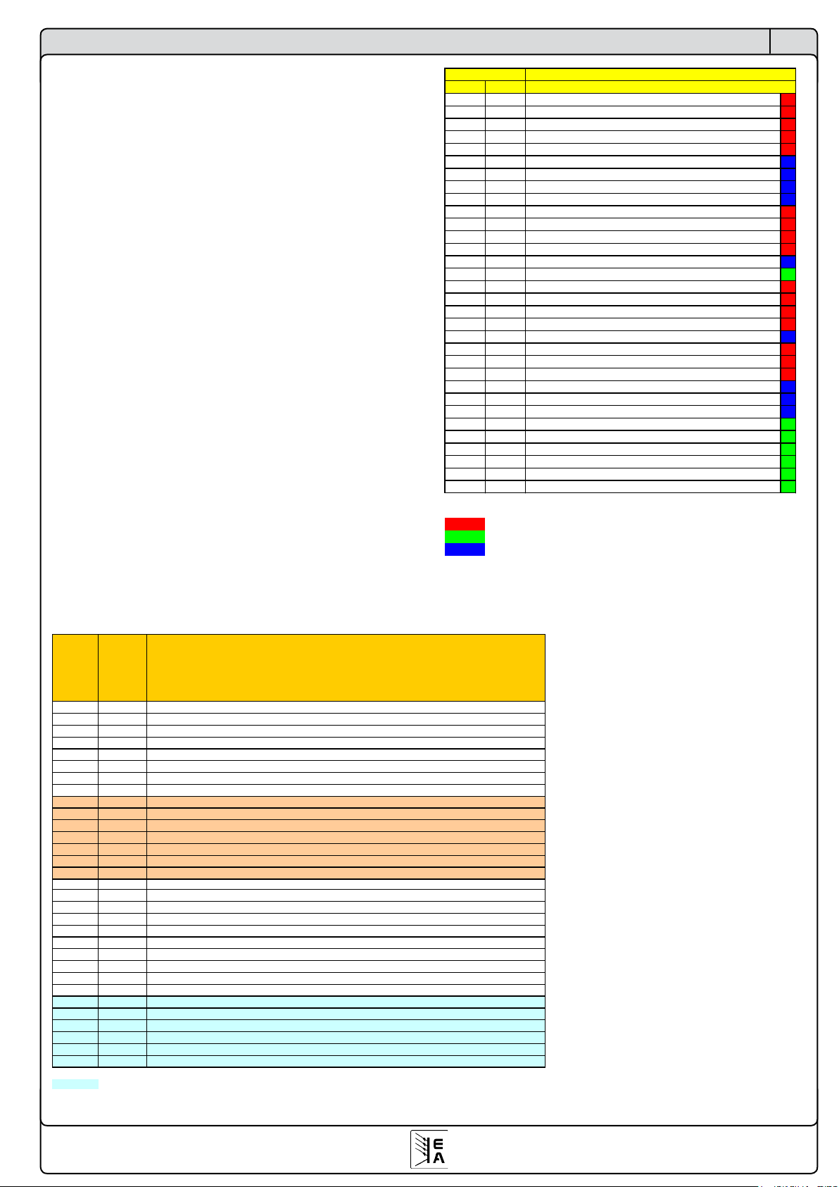
27
© 2007, Elektro-Automatik GmbH & Co. KG
Irrtümer und Änderungen vorbehalten
DE
9.4 Fehlermeldungen der Kommunikation
In der rechts stehenden Tabelle befindet sich eine Übersicht
über mögliche Fehlermeldungen, die vom anzusprechenden
Gerät an den PC geschickt werden können. Manche Fehler
sind bedingt durch eine fehlerhafte Anfrage/Sendung, andere
können ohne Aufforderung vom Gerät kommen. Sie dienen
als Hinweis und zur Fehlerfindung.
Fehlermeldungen haben Telegrammformat, d.h. sie bestehen
aus Startdelimiter, Objektnummer (falls die Fehlermeldung
als Antwort auf ein Objekt kommt) und Datenbereich. Der
Datenbereich enthält ein Byte 0xFF, das eine Fehlermeldung
kennzeichnet, und die Fehlernummer.
Beispiel: wenn man z. B. mit Objekt 50 bei einem PSI9000
die Spannung setzen will und das Gerät nicht im RemoteModus ist, dann würde sich bei einer Geräteadresse 7 das
Fehlertelegramm 81 07 FF 09 ergeben.
Übersichten
Fehlercode
Error code
Anzeigetext
Display
Fehlerbeschreibung / Description
0
Kein Fehler / No error
1
OV Überspannung am Ausgang (Eingang) / Overvoltage at output (input)
2
OT Übertemperatur im Gerät / Overtemperature inside the device
3
SYS Systemfehler / System error
4
U> Obere Spannungsgrenze überschritten / Upper voltage threshold exceeded
5
U< Untere Spannungsgrenze unterschritten / Lower voltage threshold exceeded
6
I> Obere Stromgrenze überschritten / Upper current threshold exceeded
7
I< Untere Stromgrenze unterschritten / Lower current threshold exceeded
8
SIO2 System Link Mode: Kommunikation gestört / Communication disturbed
9
MS1 System Link Mode: Ein oder mehrere Gerät sind "offline" / One or more units are offline
10
S-OV System Link Mode: Slave meldet Überspannung / Slave is reporting an overvoltage
11
S-OT System Link Mode: Slave meldet Übertemperatur / Slave is reporting overtemperature
12
S-PH System Link Mode: Slave meldet Netzfehler / Slave is reporting mains voltage error
13
S-PD System Link Mode: Slave ist in Leistungsbegrenzung / Slave reduces max output power
14
S-? System Link Mode: Slave antwortet nicht / Slave does not answer
17
F01 Interner Fehler / Internal error
19
F03 Interner Fehler / Internal error
20
CAN CAN: Kommunikation gestört / Communication disturbed
21
FCT Funktionsmanager: Funktion konnte nicht gesetzt werden / Function manager: function could not be set
22
UDU Überwachung Sprungantwort: Anstieg U / Step response supervision: U rise
23
UDD Überwachung Sprungantwort: Abfall U / Step response supervision: U fall
24
IDU Überwachung Sprungantwort: Anstieg I / Step response supervision: I rise
25
IDD Überwachung Sprungantwort: Abfall I / Step response supervision: I fall
26
PDU Überwachung Sprungantwort: Anstieg P / Step response supervision: P rise
27
PDD Überwachung Sprungantwort: Abfall P / Step response supervision: P fall
28
PH1 Phasenausfall oberes Leistungsteil / Phase loss of upper power stage
29
PH2 Phasenausfall unteres bzw. mittleres Leistungsteil / Phase loss of lower resp. middle power stage
30
PH3 Phasenausfall unteres Leistungsteil / Phase loss of lower power stage
32
OT1 Übertemperatur oberes Leistungsteil / Overtemperature of upper power stage
33
OT2 Übertemperatur unteres bzw. mittleres Leistungsteil / Overtemperature of lower resp. middle power stage
34
OT3 Übertemperatur unteres Leistungsteil / Overtemperature of lower power stage
nur bei Mehrphasengeräten / only at multi-phase models
9.5 Alarmcodes und Alarmkategorien
Was ist eine Alarmkategorie?
Über die Unterscheidung bzw. die Be-
deutung von Alarmen, Warnungen und
Meldungen bei Netzgeräten der Serie
PSI 9000 lesen Sie bitte im Benutzerhandbuch nach. Andere Geräteklassen
benutzen nur Alarmkategorie 0x01 bzw.
0x02.
Alarmkategorien:
0x01 - Alarm ist momentan aktiv
0x02 - Alarm ist nicht mehr aktiv
0x10 - Warnung momentan aktiv
0x20 - Warnung nicht mehr aktiv
0x40 - Meldung steht an
Die Alarmkategorie wird bei Anfrage, ob
Fehler aufgetreten sind (siehe Kommunikationspbjektliste), vom Gerät zusammen
mit der Fehlernummer gesendet und
können somit ausgewertet werden. Warnungen und Meldungen habe geringere
Priorität und sind daher weniger wichtig
bzw. können ggf. ignoriert werden.
Hex. Dez. Hex. Dec.
1 1 RS232: Paritätsfehler 1 1 RS232: Parity error
2 2 RS232: Frame Error (Startbit o. Stopbit nicht erkannt) 2 2 RS232: Frame Error (Startbit or Stopbit incorrect)
3 3 Prüfsumme nicht korrekt 3 3 Check sum incorrect
4 4 Startdelimiter falsch 4 4 Start delimiter incorrect
5 5 CAN: max. Nodes überschritten 5 5 CAN: max. nodes exceeded
6 6 CAN: Node unbekannt/keine Gatewayfunktion 6 6 CAN: node unknown/no gateway present
7 7 Objekt nicht definiert 7 7 Object not defined
8 8 Objektlänge nicht korrekt 8 8 Object length incorrect
9 9 Schreib-Leserechte verletzt, kein Zugriff 9 9 Read/Write permissions violated, no access
0A 10 CAN: Gateway überlastet 0A 10 CAN: Gateway overload
0B 11 CAN: Gateway-Sendepuffer voll 0B 11 CAN: Gateway send buffer full
0C 12 CAN: geteilte Message abgebrochen 0C 12 CAN: Split message aborted
0D 13 CAN: Messagebuffer überlaufen 0D 13 CAN: Message buffer overflow
0E 14 CAN: String-Startkennzeichen nicht korrekt 0E 14 CAN: String identifier incorrect
0F 15 Gerät ist in "Local" Modus 0F 15 Device is in "local" mode
10 16 CAN-Treiber-IC: Stuffing Fehler 10 16 CAN driver chip: Stuffing error
11 17 CAN-Treiber-IC: CRC-Summenfehler 11 17 CAN driver chip: CRC sum error
12 18 CAN-Treiber-IC: Übertragungsfehler 12 18 CAN driver chip: Form error
13 19 CAN: erwartete Datenlänge stimmt nicht 13 19 CAN: expected data length incorrect
14 20 CAN-Treiber-IC: Puffer voll 14 20 CAN driver chip: Buffer full
20 32 Gateway: CAN Stuffing Fehler 20 32 Gateway: CAN Stuffing error
21 33 Gateway: CAN CRC-Summenfehler 21 33 Gateway: CAN CRC check error
22 34 Gateway: CAN Übertragungsfehler 22 34 Gateway: CAN form error
30 48 Obere Grenze des Objektes überschritten 30 48 Upper limit of object exceeded
31 49 Untere Grenze des Objektes unterschritten 31 49 Lower limit of object exceeded
32 50 Zeitdefinition nicht eingehalten 32 50 Time definition not observed
33 51 Zugriff auf Menüparameter nur bei Output off 33 51 Access to menu parameter only in standby
34 52 Zugriff auf Sequenzsteuerelemente verweigert 34 52 Access to sequence control denied
35 53 Freischaltung fehlt 35 53 Feature not unlocked
36 54 Zugriff auf Funktionsdaten verweigert 36 54 Access to function data denied
37 55 Zugriff auf Sollwert verweigert (Gerät im Slavemodus) 37 55 Access to set value denied (device is in slave mode)
38 56 Objektzugriff nicht erlaubt 38 56 Object access denied
Legende Legend
Kommunikationsfehler Communication error
Userfehler User error
Interner Fehler Internal error
Description
Fehlercode
Error code
Beschreibung
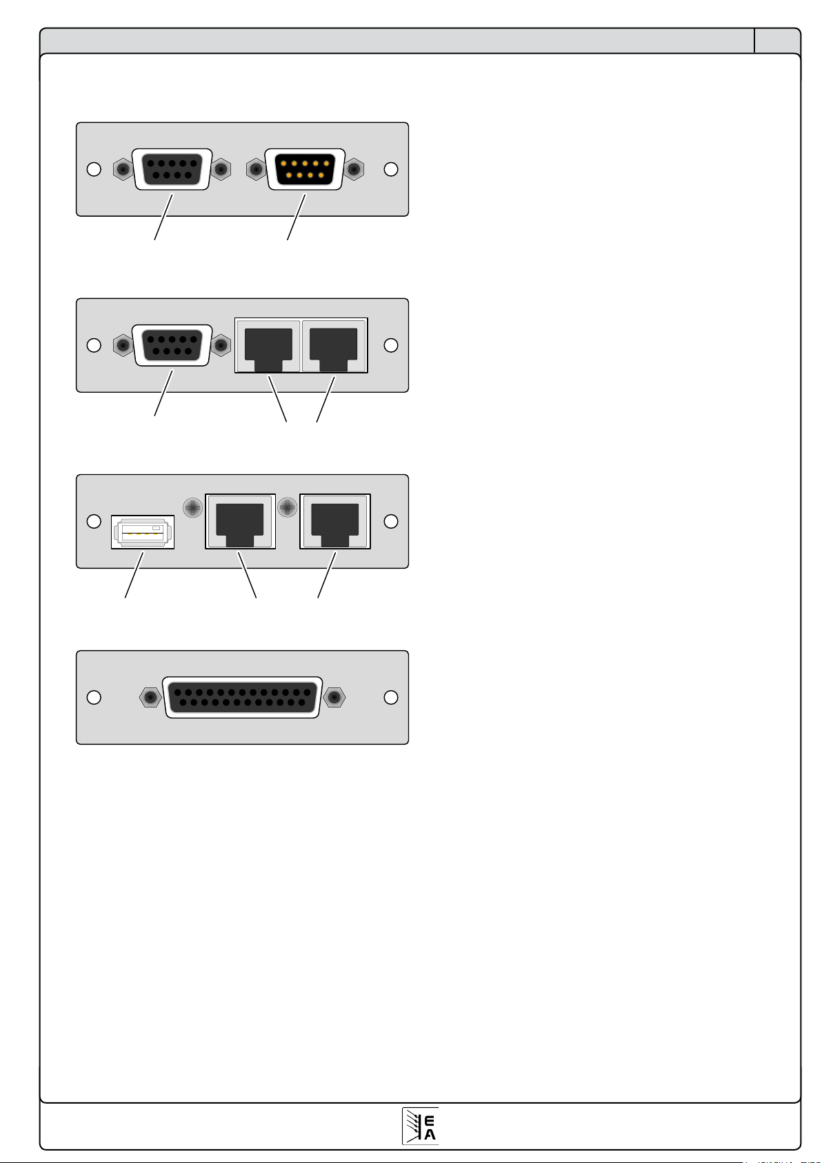
28
© 2007, Elektro-Automatik GmbH & Co. KG
Irrtümer und Änderungen vorbehalten
DE
Übersichten
10. Anschlüsse
IF-C1
CAN1
CAN2
IF-R1
RS232 System Link Ports
IF-U1
System Link Ports
USB A
IF-A1
1
Hinweis:
Die Anschlüsse der CAN-Karte sind parallel
geschaltet
Hinweis:
Die System Link Ports sind nur nutzbar mit Netz-
geräten der Serie PSI9000. Niemals EthernetKabel hier einstecken!
Hinweis:
Die System Link Ports sind nur nutzbar mit Netz-
geräten der Serie PSI9000. Niemals EthernetKabel hier einstecken!

29
© 2007, Elektro-Automatik GmbH & Co. KG
EN
Important!
• Only equip the interface card(s) in units which are designed
to be used with them! It is not required to open the unit. Information about which devices are capable of running these
interface cards can be requested from your local dealer or
read in the user instruction manual of the devices.
• Only equip the interface card(s) while the unit is switched
off by the mains switch!
• Units featuring two slots might be equipped with two cards,
but you can’t combine them arbitrarily. For detailed information see section „3.3 Combination of interface cards“
• Never remove the covers from the cards!
• If only one card is equipped in units with two slots it is
recommended to install the default slot cover to the open
slot. This protects the unit from additional dust pollution and
ensures correct air circulation with the internal fans.
• Use and follow the common ESD provisions when installing
and removing the interface cards!
About & Copyright
User instruction manual for interface cards
Elektro-Automatik GmbH & Co. KG
Helmholtzstrasse 31-33
41747 Viersen
Germany
Phone: +49 (0)2162 / 37850
Fax: +49 (0)2162 / 16230
Web: www.elektroautomatik.de
Mail: info@elektroautomatik.de
© 2007 Elektro-Automatik
Reprint, duplication or partly, wrong use of this user instruction manual are prohibited and might be followed by legal
consequences.
Date: May, 2007

30
© 2007, Elektro-Automatik GmbH & Co. KG
EN
Index
Page
1. General 31
1.1 Usage 31
1.2 The concept 31
1.3 Warranty/Repair 31
1.4 Used symbols 31
1.5 Scope of delivery 31
2.Technicalspecications 32
3. Installation 33
3.1 After unpacking 33
3.2 Inserting a card 33
3.3 Combining interface cards 33
4. Usage in devices of series PSI 9000 33
4.1 RS232 card IF-R1 34
4.1.1 ConguringtheIF-R1 34
4.2 USB card IF-U1 34
4.2.1 ConguringtheIF-U1 34
4.3 CAN card IF-C1 34
4.3.1 ConguringtheIF-C1 35
4.4 Analogue interface IF-A1 36
4.4.1 Pin assignment of the analogue interface (25-pole D-Sub socket) 36
4.4.2 General 37
4.4.3 ConguringtheIF-A1 37
5. Usage in devices of the series EL3000/EL9000 40
6. The System Link Mode (only PSI9000) 41
6.1 Handling the System Link Mode 41
6.1.1 Display and handling of the master 41
6.1.2 Display of the slaves 41
6.1.3 Special alarms, warnings and signals 42
6.2 Configuration of the System Link Mode 42
7. Communication in detail 43
7.1 Terms explained 43
7.2 Prologue 43
7.3 General notes about the communication 43
7.4 About the USB driver 43
7.5 Structure of the communication 44
7.6 Telegram structure IF-R1 and IF-U1 44
7.6.1 Translating set values and actual values 45
7.7 Message structure for the IF-C1 45
7.7.1 Split messages 45
7.7.2 Timing of messages 45
8. Utilities for the communication 46
8.1 Overview about the Labview VIs 46
8.1.1 Short info Communication VIs 47
8.1.2 Short info Standard VIs 47
9. Guide to program the interface cards 48
9.1 Explanation of the communication object list 48
9.2 Approach 48
9.3 Communication object list 50
9.3.1 For devices of the series PSI9000 50
9.3.2 For devices of the series EL3000A/EL9000A 53
9.4 Error messages of the communication 54
9.5 Alarm codes and alarm categories 54
10. Connectors 55

31
© 2007, Elektro-Automatik GmbH & Co. KG
EN
About the interface cards
1. General
The interface cards IF-R1, IF-C1 and IF-U1 provide a digital
and IF-A1 an analogue connection to a control unit like a
PC or Siemens SPS. The devices, like for instance a power
supply, can be monitored, controlled and configured using
the cards and the proper software. In combination with an
IF-C1 card the user can realise a gateway from the RS232
or USB port of the PC to the CAN bus. Thus no extra hardware is required to connect the PC to CAN. The gateway
allows to control up to 30 units in line by the RS232/USB
and CAN cards.
If a device has been equipped with an interface card, it is
automatically reognized and the corresponding setup menus
are available for configuration.
Those setup menus differ from model to model and are used
to set up parameters for the communication. The settings
are stored inside the unit.
The cards IF-R1 and IF-U1 additionally support the parallel
and/or series connection of multiple laboratory power supplies of the series PSI 9000 (System Link Mode).
The analogue interface card IF-A1 is directly accessing the
power supply. This allows fast monitoring of actual values and
fast setting (with a very short delay) of set values, within the
nominal values of the device. The digital inputs and outputs
parameterisable.
1.1 Usage
The interface cards must only be equipped in units which
are designed for them.
A set of Labview VIs is included in the package, which will
simplify the use and implementation of the interface cards
in the LabView IDE.
The implementation in other applications and environments
is possible, but also very complex. The telegram structure is
explained in detail in on of the following sections.
The voltage range of the analogue input and output signals
of the IF-A1 is customisable between 0 and 10V. The digital
inputs can be switched between two different voltage ranges for the logical level and the default logical level can be
predefined for the case these inputs are not used.
1.2 The concept
The interface cards are pluggable and can thus be used
where needed. They are compatible to various types of
devices, such as electronic loads. Due to the electrical isolation of 2000V you can also connect multiple devices with
different potentials.
The digital cards IF-R1, IF-C1 and IF-U1 support a unique
communication protocol, which is object orientated. Every
type of device has an internal object list, which differs depending on the features of the device. The transmitted objects
are checked for validity and plausibility. Non-plausible or
erroneous values and objects result in an error which is sent
as an answer telegram.
1.3 Warranty/Repair
Attention: The interface must not be repaired by the user!
In case of warranty or a defect please contact your local
dealer to get informed about the next steps. The cards are
conceded with a statutory warranty of two years (for Germany), which is independent from the warranty (and its length)
of the device they are used in.
1.4 Used symbols
In the following description the display and operating
elements are marked differently by symbols.
= Displayed only, all elements which are only
displayed and which represent a state are marked with
this symbol
= Parameter, changeable values, are marked with
this symbol and are emphasised
= Menu items, selectable, lead to the next sublevel or
to the bottom level with parameters
Brackets {…} mark possible options or adjustment ranges
for parameters.
1.5 Scope of delivery
1 x Pluggable interface card
1 x Software CD with user instruction manuals
1 x Short installation guide
1 x Patch cable 0.5m 1:1 (only at IF-R1 and IF-U1)

32
© 2007, Elektro-Automatik GmbH & Co. KG
EN
2.Technicalspecications
General
Electrical isolation 2000V
Dimensions (W x H x L) 24 x 80 x 100mm
Safety EN 60950
EMI Standards EN61000-6-4,
EN 61000-6-2,
EN 55022 Class B
Overvoltage category Class II
Operation temperature 0...40°C
Storage temperature -20...70°C
Relative humidity <80% (w/o condensation)
Accessory Labview VIs
IF-R1 (RS232)
Connectors 1 x 9-pole D-Sub socket (f.)
2 x RJ45 socket
Baud rates 9600Bd, 19200Bd,
38400Bd, 57600Bd
Cable length depending on the baud rate,
up to 15m
System Link Mode yes
(only with series PSI 9000)
└Max.numberofunits 30
└Bustermination settableintheunit’smenu
└Patchcable 0.5m
IF-U1 (USB)
Connectors 1 x USB socket type A
2x RJ45 socket
Standard USB 1.1
Cable length max. 5m
System Link Mode yes
(only with series PSI 9000)
└Max.numberofunits 30
└Bustermination settableintheunit’smenu
└Patchcable 0.5m
IF- C1 (CAN)
Connectors 9-pole D-Sub socket (f.)
9- pole D-Sub socket (m.)
Baud rates 20kBd...1MBd in steps
Bus termination settable in the unit’s menu
CAN standard V2.0 part A
About the interface cards
IF-A1 (Analogue)
Connectors 25-pol D-Sub socket(f.)
Analogue inputs:
Input voltage range
Maximum range -5V...+15V
Nominal range 0V…10V
Inputimpedance 25kΩ
Resolution
VSEL, CSEL, PSEL (RSEL) < 2mV
Relative error
VSEL, CSEL, PSEL 0.1%
RSEL (Option) 0.25%
Response time1) < 4ms
Analogue outputs:
Nominal output voltage range
VMON, CMON, PMON 0V…10V
I
out
max. at 10V 2mA
VREF 1V...10V
I
out
max. at 10V 10mA
Resolution
VMON, CMON, PMON, VREF < 2mV
Relative error
VMON, CMON, PMON, VREF 0.1%
Settling time of the analogue outputs < 4ms
Auxiliary voltage 12…15V
Current max. 50mA
Digital outputs:
Typ e pull-up resistor to +15V
Output current
Maximal I
max
= -20mA
at U
out
= 0.5V
Nominal 1...10mA
Output voltage
High +15V
Low < 0.3V
Response time2) < 4ms
...continued
1 In order to calculate the total response time of a step change, from an analogue
interface input to the power output you need to add the response time of the device
to this time.
2 Timebetweenoccurence oftheevent,whichis abouttobenotied,andthemo-
mentthenoticationisexecuted.

33
© 2007, Elektro-Automatik GmbH & Co. KG
EN
About the interface cards
Digital outputs:
Input voltage
Maximum range -5V...+30V
if set to: Level=LOW
U
Low
< 1V
U
High
> 4V
if set to: Level=HIGH
U
Low
< 5V
U
High
> 9V
Input current
if set to Low Range and Default Level = L
Uin= 0V 0mA
Uin= 12V +2.6mA
Uin= 24V +5mA
if set to Low Range and Default Level = H
Uin= 0V -1.5mA
Uin= 12V +2.2mA
Uin= 24V +6mA
if set to High Range and Default Level = L
Uin= 0V 0mA
Uin= 12V +1.6mA
Uin= 24V +3.5mA
if set to High Range and Default Level = H
Uin= 0V -1.5mA
Uin= 12V +0.7mA
Uin= 24V +4.5mA
Response time1) < 10ms
1 Time between occurance of an event, that has to be signalised to an
output, and the moment it is signalised.
3. Installation
3.1 After unpacking
After unpacking, check the pluggable interface card(s) for
signs of physical damage. If any damage can be found do
not use and insert the card into any device!
3.2 Inserting a card
The card(s) must only be equipped while the unit is completely switched off. The unit does not have to be opened.
Remove the screws from the slot cover or from an already
equipped card and remove the cover/card. Insert the new
card with caution until the card plate touches the rear side of
the unit. If there is space between the rear side and the
card plate, do not tighten the screws, because the card
is not placed correctly! The wiring between the PC and/or
other units has also be done before the unit is switched on
again. The card(s) will be automatically detected by the device after powering it on and can now be configured.
Note about the IF-A1: before equipping the card, you should
set the jumpers correctly. Refer to „4.4.1 Configuring the IFA1“, subsection „Digital inputs“.
Note: in case the card is not recognized after switching the
unit on, it might be necessary to update the firmware of your
device. Please contact you dealer for further information.
Caution: There are components on the card which are
sensitive for ESD. You must follow the general ESD provisions when handling and installing a card.
3.3 Combining interface cards
At models with more than one card slot following restrictions
apply:
- never equip two cards of the same type
- the cards IF-R1 and IF-U1 must not be equipped together
4. Usage in devices of series PSI 9000
The interface cards are designed to be used in various type of
devices. Depending on the typical features of a certain device
type, like an electronic load, the resulting operation variety
differs. This section handles the configuration and handling
of the cards if used in laboratory power supplies of the series
PSI 9000. If you have purchased a different type of device,
please read further in the corresponding sections
Information about the handling and navigation in the menus
and parameter pages of the various device types is available
the corresponding user instruction manuals.

34
© 2007, Elektro-Automatik GmbH & Co. KG
EN
4.1 RS232 card IF-R1
The RS232 interface card IF-R1 links the power supply
with a controlling unit (PC) via its serial port, also called
COM port. The settings of this serial connection have to be
confi-gured on both ends to the same values. At the power
supply this is done in the setup menu. A 1:1 cable has to
be used.
The IF-R1 features an additional serial interface which is
used to link multiple power supplies in order to build the
System Link Mode. More information about it in section „6.
The System Link Mode (only PSI9000)“.
Never connect any of these ports to an Ethernet hub
or switch or Ethernet port of a PC!
4.1.1 ConguringtheIF-R1
The interface card is configured in the setup menu.
It is absolutely necessary to choose and set a unique device
address, also called „device node“, for every connected or
linked unit. Only then a unit can be identified and controlled
correctly. This address is used to access a device.
Activate the menu with
M
+Communication+
device node Default: 1
= {1..30} Choose one of up to 30 device nodes
Slot A : { IF-… } depends on the equipped card
Slot B : { IF-… } depends on the equipped card
Here you set the desired device node and you also get an
overview which cards are currently installed. By selecting
a card with
Slot {A|B}: IF-R1 +
you enter the configuration menu for that particular card.
Each card has to be configured individually. You can now
setup the parameters:
Baud rate Default: 57.6 kBd
= {9.6 kBd, 19.2 kBd, 38.4 kBd, 57.6 kBd}
The selected baud rate has to be determined in dependency
of the used cable length. At 15m a maximum of 9.6 kBd is
allowed. 1kBd = 1000Bd.
4.2 USB card IF-U1
The USB interface IF-U1 works similiar to the RS232 card,
but it is more comfortable when connecting multiple units to
a PC via an USB hub. You can connect and control up to 30
units with only one PC and one USB port.
The IF-U1 features an additional serial interface which is
used to link multiple power supplies in order to build the
System Link Mode.
Never connect any of these ports to an Ethernet hub
or switch or Ethernet port of a PC!
More information about it in section „4.5 System Link
Mode“.
4.2.1 ConguringtheIF-U1
The interface card is configured in the setup menu.
It is absolutely necessary to choose and set a unique device
address, also called „device node“, for every connected or
linked unit. Only then a unit can be identified and controlled
correctly. The address is used to access a unit.
Activate the menu with
M
+Communication+
device node
Default: 1
= {1..30} Choose one of up to 30 device nodes
Slot A : { IF-… } depending on the equipped card
Slot B : { IF-… } depending on the equipped card
Here you set the desired device node and you also get an
overview which cards are currently installed. A further configuration of the USB card is not required.
4.3 CAN card IF-C1
CAN Standard: V2.0 part A (on request: V2.0 part B)
Cable length: depending on the baud rate
Specialty: Gateway to RS232 cards or USB cards
The communication over the CAN bus is specifically desi-
gned to suit the needs of test applications and systems, like
for instance in the automotive industry. A subsequent implementation into existing systems and the modification of a
related software application is possible and unproblematic.
The networking of CAN devices provides the advantage of
a faster communication and a fail-safe bus topology. The
driver chip on the CAN card can support up to 110 device
nodes (the term device node is used for address at CAN).
The LabView software resp. the communication protocol
can handle up to 30 units per address segment. Thus it is
theoretically possible to set up a bus system of up to 110
units, which will operate with at least 4 address segments.
The address segments are relocatable, so that the one ore
multiple devices can be implemented into an existing CAN
bus without the need to reconfigure the whole system.
About the interface cards

35
© 2007, Elektro-Automatik GmbH & Co. KG
EN
4.3.1 ConguringtheIF-C1
The interface card is configured in the setup menu.
It is absolutely necessary to choose and set a unique device
address, also called „device node“, for every connected or
linked unit. Only then a unit can be identified and controlled
correctly. This address is used to access a unit.
Activate the menu with
M
+Communication+
device node Default: 1
= {1..30} Choose one of up to 30 device nodes
Slot A : { IF-… } depending on the equipped card
Slot B : { IF-… } depending on the equipped card
Here you set the desired device node and you also get an
overview which cards are currently installed. By selecting
a card with
Slot {A|B}: IF-C1 +
you enter the configuration menu for that particular card.
Each card has to be configured individually. You can now
setup the parameters:
Setting the baud rate
All common baud rates are supported. For each baud rate
setting the so-called „Sample point“ can be chosen, which
is used to optimise the data transmission for various cable
lengths and qualities. It adjusts the point of time when a
transmitted bit is sampled.
baudrate Default: 100 kBd
sample point: 75%
= { 10 kBd { 60, 65, 70, 75, 80, 85}%,
20 kBd { 60, 65, 70, 75, 80, 85} %,
50 kBd { 60, 65, 70, 75, 80, 85} %,
100 kBd { 60, 65, 70, 75, 80, 85} %,
125 kBd { 58, 68, 70, 75, 81, 87} %,
250 kBd { 58, 68, 70, 75, 81, 87} %,
500 kBd { 58, 66, 75, 83} %,
1 MBd { 58, 66, 75, 83} % }
Relocating address segments
In case that a device is retrofitted with a CAN card and
implemented into an existing CAN bus system, the „reloca-
table identifier segment“ (short: RID) is used to relocate the
address segment in order to adapt the address of the new
unit to the address range of the already exisiting units or to
set it away from that range to not collide.
The CAN bus after the standard V2.0a defines an 11 bits
long address (=identifier). This results in a total of 2032
identifiers from which can be chosen. Those 2048 identifiers
are seperated into 32 address segments of 64 addresses.
The starting address is determined by the RID.
relocatable ID Default: 0
segment = { 0..31} Select (relocate) the address range
Inside of every address segment are 62 freely assignable
addresses, whereas the up to 30 units are using the lower
range and with 2 physical adresses (identifiers, one each
for sending and requesting data) per unit they are taking
the addresses from 2...61. The addresses 0 and 1 of every
address reange are reserved for broadcast messages. This
also results in 32 boradcast addresses.
For broadcast messages the addresses are static:
[RID*64 + 0] and [RID*64 + 1].
Example: the RID is set to 5 (also see setup menu of
your device). A broadcast shall be sent to all units of this
address range. The identifier hence calculates as 5*64 =
320 (0x140).
For singlecast messages every „device node“ is occupying another two addresses:
[RID*64 + device node * 2] and
[RID*64 + device node * 2 + 1]
Example: the RID was set to 13, the device address (node) to
12. In order to send a message to that device, the identifier has
to be: 13*64 + 12*2 = 856 (0x358). The identifier 857 (0x359)
is used for answers and requests.
Bus termination
The CAN bus requires a termination resistor of 120 Ohms
on both ends of the line. If a unit is located at the end of the
chain/line and it is not connected to a next unit, it has to be
terminated. The parameter „bus terminate“ is used to easily
set the termination without any circumstancial hardware
termination by jumpers.
bus terminate Default: NO
=YES The bus is terminated with a 120Ω resistor.
=NO No termination is done.
Gateway function (only PSI9000)
CAN Default: Client
=Client The device is monitored and controlled by an
external unit, like a PC or a SPS
=Gateway The interface card serves as a gateway bet-
ween CAN and RS232/USB card
The RS232 or USB card inside the device with the gateway
allows the user to control and monitor all further units, which
are linked to that particular device by CAN. All that is needed
is a device with IF-R1 or IF-U1 interface card to set up a CAN
bus system. Both cards, RS232 and USB, can only utilise
the high performance of the CAN bus very poorly. In order
to use the CAN bus with full performance (high data rate)
and many devices, it is recommended to directly control the
bus with a CAN control hardware.
About the interface cards

36
© 2007, Elektro-Automatik GmbH & Co. KG
EN
About the interface cards
4.4 Analogue interface IF-A1
4.4.1 Pin assignment of the analogue interface (25-pole D-Sub socket)
Pin Name Function Description Level Electricalspecications
1 AI1 PSEL / RSEL
Analogue input:
Set value power / resistance
0..10V correspond to
0..100% von P
nom
/ R
nom
Er < 0.1%1)
Input impedance Ri > 25k
2 AI2 VSEL
Analogue input:
Set value voltage
0..10V correspond to
0..100% von U
nom
3 AI3 CSEL
Analogue input:
Set value current
0..10V correspond to
0..100% von I
nom
4 AO1 PMON
Analogue output:
Actual value power
0..10V correspond to
0..100% von P
nom
Er < 0.1%1) at I
max
= +2mA4)
Short-circuit-proof against GND
5 AO2 VMON
Analogue output:
Actual value voltage
0..10V correspond to
0..100% von U
nom
6 AO3 CMON
Analogue output:
Actual value current
0…10V correspond to
0..100% von I
nom
7 DO1 CV
Digital output:
Constant voltage operation „CV“
CV = Low
No CV = High
Quasi open collector with pull-up resistor
against VCC
I
max
= -10mA4) at U
low
= 0.3V
U
max
= 0...30V
Short-circuit-proof against GND
Receiver: U
low
< 1V; U
high
> 4V)
8 DO2 OVP
Digital output:
Overvoltage protection active
OVP = High
No OVP = Low
9 DO3 OT
Digital output:
Overtemperature error
OT = HIGH
No OT = Low
10 DO4 Mains
Digital output:
Mains voltage present
Mains present = Low
No mains = High
11 DO5 Standby
Digital output:
Output Off
Output OFF = Low
Output ON = High
12
DO6 CC
Digital output:
Constant current operation „CC“
CC = Low
No CC = High
13 DO7 CP
Digital output:
Constant power operation „CP“
CP = Low
No CP = High
14 AGND SEL
2)
Reference potential of the
analogue inputs
Reference for SEL signals
15
AGND
2)
Reference potential of the
analogue outputs
Reference for MON signals and VREF
16
17 N.C.
18 AO0 VREF
Analogue output:
Reference voltage
10V
Fr < 0.1%1), I
max
= + 8mA4)
Short-circuit-proof against GND
19 +VCC
Auxiliary voltage
(Reference: DGND)
12V…16V
I
max
= +50mA4)
Short-circuit-proof against DGND
20
DGND
2)
Reference potential of the digital
ports
Reference for +VCC, control and
noticationsignals
21
22 DI1 SEL-enable
Digital input:
Switch-over to external interface
(else: local operation)
Jumper set to „Low
Level“:
SEL-enable on = Low
SEL-enable off = High
Presettable input level (High/Low range):3)
1) U
Low
= < 1V ; U
High
= > 4V or
2) U
Low
= < 5V ; U
High
= > 9V
Presettable logic level if input is not wired:
open = High Level or Low Level
23 DI2
Rem-SB
Digital input:
Output off
Jumper set to „Low
Level“:
Output on = Low
Output off = High
24
Reserved
25
N.C.
1) Er - relative error. It describes the relation between set value and actual value and is given as the max. difference from the nominal value, in per cent.
2)AGNDandDGNDareconnectedinternally.AGNDSELatPin14isinpedendent.Itservesasreferenceforthedifferenceampliersofallanalogueinputs.
DIx, DOx, +Vcc are referenced to DGND. VREF, VMON, CMON, PMON are referenced to AGND. VSEL, CSEL und PSEL are referenced to AGND SEL.
3) Digital input, depending on the preset with the jumpers:
a) Setting High Range (high threshold): Uin = 0V; I = -1.5mA, Uin = 12V; I = +0.7mA; Uin = 24V; I = +4.5mA, Thresholds: U
Low
= < 5V; U
High
= > 9V
b) Setting Low Range (low threshold): Uin= 0V; I = -1.5mA, Uin = 12V; I = 2.2mA, Uin = 24V; I = +6mA, Thresholds: U
Low
= < 1V; U
High
= > 4V
4)Positivecurrentsareowingoutofthedevice,negativecurrentsareowingintoit.

37
© 2007, Elektro-Automatik GmbH & Co. KG
EN
About the interface cards
4.4.2 General
The interface IF-A1 is an analogue interface with galvanically isolated, parameterisable, analogue inputs and outputs
and some not galvanically isolated, parameterisable, digital
inputs and outputs. That means, that you can customise
these inputs and outputs to your needs, but always within
a voltage range of 0...10V. At devices with two extension
card slots (eg. PSI9000) it is possible to combine the IF-A1
with a digital interface card (eg. IF-U1 (USB)), in order to
control, for example, the device by USB and put out actual
values via the analogue outputs of the analogue card. Or
vice versa, you control the device by analogue set values
and read out and log the actual values to a PC via RS232,
CAN or USB.
Generally applies: all monitoring and surveillance features
are permanently active, even if two card (one digital, one
analogue) are equipped. Only the control of the device with
set values requires the activation of the external mode (IFA1) resp. of the remote mode (digital interfaces), whereas
the remote mode (control by a digital interface card)
has priority. In case the device is in control by the analogue
interface (external mode, indicated in the display by ex-
tern) and the control of the device via a digital interface is
activated, the device will switch to remote mode (indicated
in the display by remote).
4.4.3 ConguringtheIF-A1
The interface is configured in the communication menu:
M
+Communication+
Slot A : { IF-… } Name of 1st interface card (if equipped)
Slot B : { IF-… } Name of 2nd interface card (if equipped)
Here you can see an overview of the equipped cards.
With:
Slot {A|B}: IF-A1 +
the analogue interface card is selected for configuration.
Following parameters can be set:
Analogue inputs
Analogue set values are only accepted by the device if it is
in external mode (indicated in the display by extern).
The analogue interface IF-A1 has three analogue inputs
with these features:
AI1: PSEL (external set value for power) or RSEL (external
set value for inner resistance, optional at unlocked
U/I/R operation)
AI2: CSEL (external set value for current)
AI3: VSEL (external set value for voltage)
The minimum and maximum input voltage kan be preset.
The analogue inputs can be adapted the input signal this
way. By limitting the standard voltage range of 0...10V to a
lower value the resolution is also lowered. Example: if the
voltage range is set to 1V difference between U
max
and U
min
,
resolution and accuracy will be reduced by the factor 10.
The first value stands for U
min
(minimum input voltage), the
second for U
max
(maximum input voltage). It applies:
U
min
= { 0.00V... 4.00V }
U
max
= { 4.00V... 10.00V }
The adjusted voltage range, for example 2.00V...8.00V, corresponds to 0...100% set value. A higher or lower voltage is
treated as either U
min
or U
max
.
AI1 Default: Psel 0.00 10.00V
= {Psel | Rsel} external set value for power/resistance
Rsel is only available if U/I/R mode is unlocked.
AI2 Default: 0.00 10.00V
= Vsel external set value for voltage
AI3 Default: 0.00 10.00V
= Csel external set value for current
Analogue outputs
The actual values of output voltage, current and power are
led out to the analogue outputs. These outputs can be adapted to custom requirements. The first value stands for U
min
(minimum output voltage), the second for U
max
(maximum
output voltage). It applies:
U
min
= { 0.00V... 9.00V }
U
max
= { 4.00V... 10.00V } wobei gilt: U
max
> U
min
By limitting the standard voltage range of 0...10V to a lower
value the resolution is also lowered. Example: if the voltage
range is set to 1V difference between U
max
and U
min
, resolution
and accuracy will be reduced by the factor 10.
The reference voltage is an exception. It can be set to a
value between 1V and 10V.
AO0 Default: 10.00V
= Vref Adjustable reference voltage in a range of
{1V.. 10V}.
AO1 Default: 0.00V 10.00V
= Pmon Monitor (actual value) output power
AO2 Default: 0.00V 10.00V
= Vmon Monitor (actual value) output voltage
AO3 Default: 0.00V 10.00V
= Cmon Monitor (actual value) output current

38
© 2007, Elektro-Automatik GmbH & Co. KG
EN
About the interface cards
Digital inputs
The interface card IF-A1 has three parameterisable digital
inputs DI1, DI2 and DI2(not used, reserved).
DI1/SEL_enable Default: LOW
external
= LOW External control of the device by IF-A1 is low
active. If the default logical level of DI1 is set to
LOW by the jumper on the PCB, the external
control will be instantly active when switching
the device on.
= HIGH External control of the device by IF-A1 is high
active.
After the external control has been actived, the power supply
can be controlled by the inputs VSEL, CSEL and/or PSEL.
The status signale and analogue actual values are always
put out.
Note: the power supply output can always (exception: explicit
local mode) be shut down with the input DI2/Rem-SB, even
if external mode is not active.
extern The display indicates, that the device is in external
control by the analogue interface.
DI2/Rem-SB
You can switch the power supply output on and off, enable
or block it with this input. Depending on the setting Set
output, the input DI2/Rem-SB determines whether the out-
put is controlled exclusively in external mode (by analogue
interface) respectively remote mode (by digital interface) or if
it requires to be enabled by the ON/OFF key. The enabling is
indicated in the display with auto ON. Using the exclusive
On/Off setting, the power output is directly controlled by the
input DI2/Rem-SB. Attention! This can‘t be interrrupted by
the ON/OFF key on the front or by a command from a digital
interface card (exception: the device is in „local“ mode, then
the imput is ignored).
DI2/Rem-SB
Set output Default: enable ON
= enable ON The ON/OFF key has to be used to
enable the input
= exlcusive The power supply output can only be
switched on and off by the input DI2/
Rem-SB or via a digital interface card
(if equipped)
When using the setting enable ON, the output needs to be
enabled at least once. By the setting Power ON = restore
(seecongurationmenuofyourdevice)thepoweroutput
will be automatically enabled after a mains loss, if it has
been enabled before the mains loss occured. It can then be
switched on or off as normal.
Standby
Default: LOW
= LOW The input is low active, standby is activated
with a voltage level <1V or <5V (depending
on the jumper setting)
= HIGH The input is high active, standby is activated
with a voltage level >4V or >9V (depending
on the jumper setting).
The figure shows the chaining of the various states and conditions for local, remote and external mode when switching
the power output on or off:
Jumper settings for DI1-3
The jumpers DI1-3 on the PCB are used to preset the phy-
sical behaviour of these inputs. The selector „Default level“
defines the default logical level of the corresponding input.
That means, if the default logical level is set to High, the input
has to be pulled actively to Low by an external application
(eg. relay) in order to change its logical level. The default
logical level requires attention, since it defines the behaviour
of the power supply by the control signals SEL_enable and
Rem-SB.
Default level defines the logical level of the input if not
wired.
High range selects the high input voltage range for the
input. A „high“ corresponds to a voltage of >9V and a „low“
to a voltage of <5V.
Low range selects the low input voltage range for the input.
A „high“ corresponds to a voltage of >4V and a „low“ to a
voltage of <1V.

39
© 2007, Elektro-Automatik GmbH & Co. KG
EN
About the interface cards
Examples: the input DI2/Rem-SB, which is used to switch
the power output on and off (standby), can be activated with
LOW or HIGH, depending on what has been configured in
the setup.
Example 1: the input shall be pulled to GND by a relay (maker
contact) and switch the power output off. Hence you need
to configure the jumper for DI2 to „Default level = H“ and
use the settings Standby = LOW and Set output = enable
ON. The output of the power supply can then be switched
by the relay.
Example 2: the output shall be shut off by an emergency
circuit. The jumper for DI2 needs to be set to „Default level
=L“ and the setting Standby = LOW. This example uses a
relay with a maker contact to Vcc.
There are, of course, many other possible combinations.
Digital outputs with determined functionality
The digital outputs DO1, Do4 and DO7 can not be userdefined in their functionality, but they can invert the logical
output level.
DO1/CV Default: LOW
= { LOW | HIGH }
If LOW has been selected, the output is pulled to GND as
soon as the regulation mode of the power supply is determined by the set value of voltage (CV operation). If HIGH has
been selected, the output is pulled to 12...15V.
DO4/Mains OK Default: LOW
= { LOW | HIGH }
If LOW has been selected, the output is pulled to GND as long
as the mains voltage is present. If HIGH has been selected,
the output is pulled to 12...15V.
DO5/Standby Default: LOW
= { LOW | HIGH }
If LOW has been selected, the output is pulled to GND if the
power output of the device is off (standby). If HIGH has been
selected, the output is pulled to 12...15V.
DO6/CC Default: LOW
= { LOW | HIGH }
If LOW has been selected, the output is pulled to GND as
soons as the regulation mode of the power supply is determined by the set value of current (CC operation). If HIGH
has been selected, the output is pulled to 12...15V.
Digitaloutputswithuser-denablefunctionality
ThedigitaloutputDO2,DO3,DO7,DO7canbecongured
as desired and the logical level can be inverted.
DO2 Default: OVP LOW
DO3 Default: OT LOW
DO7 Default: CP LOW
One of the following functions can be assigned to each of
the outputs:
= remote Indicates that the power supply is remotely-
controlled via a digital interface card.
= OT Indicates an overtemperature error.
= CP Indicates that the power supply regulated by
the set value of power (CP operation).
= Alarm Indicates that an alarm has happened. The
output of the power supply is automatically
shut down and the alarm can be indicated by
this output.
= trip U Triggered by overstepping of the limits U>
and/or U< (see user‘s guide of PSI9000).
= trip I Triggered by overstepping of the limits I>
and/or I< (see user‘s guide of PSI9000).
= trip U+I Triggered by overstepping of the limits U>, U<,
I> and/or I< (see user‘s guide of PSI9000).
Deningthelogicallevelwhentriggered/indicated:
= LOW The output is pulled against GND as soon as
the selected function becomes active. The
logical level is inverted, if the condition is not
true.
= HIGH The output is pulled against +15V by a high
resistance resistor as soon as the selected
function is active. The logical level is inverted,
if the condition is not true.

40
© 2007, Elektro-Automatik GmbH & Co. KG
EN
About the interface cards
5. Usage in devices of the series EL3000/EL9000
The electronic loads of the series EL3000 and EL9000 support the following interface cards:
IF-U1, IF-R1, IF-C1
The general functionality of the interface cards is the same
if used in one of these electronic loads. The amount of features is limited, compared to a power supply, and there’s a
difference in configuring the cards in the setup menu.
Menu example of the CAN card:
Menu example RS232 card:
You can configure the interface cards in the setup menu of
the devices. This is activated by turning the switch Level
Control to position Setup.
Depending on which card is equipped (the electronic loads
feature only one card slot) a different selection of parameters
is available. The parameters and their values are identical to
the ones explained in section 4.1 to 4.3, with the exception
that no Sample point can be set at CAN.
There are also no settable parameters for the USB card
here.
Card found: IF-C1
CAN Baudrate: 10kBd
Card found: IF-C1
CAN Relocatable ID: 13
Card found: IF-C1
CAN Bus terminate: yes
Card found: IF-R1
RS232 Baudrate: 9600Bd
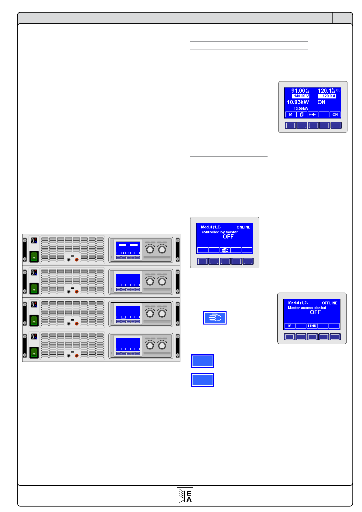
41
© 2007, Elektro-Automatik GmbH & Co. KG
EN
About the interface cards
6. The System Link Mode (only PSI9000)
The System Link Mode (only at series PSI9000) supports
the parallel and serial connection. Without an extra interface
any device will display its own actual/set values and errors,
when using the devices in master-slave configuration in
parallel or serial or in parallel with the Share bus. The set
value and actual value of voltage has to be multiplied by the
number of serially connected units. The parallel connection
acts analogously to the serial connection. Here the current
set value and actual value have to be multiplied.
The System Link Mode transfers the actual values from the
slaves to a definable master and the set values vice versa.
The master displays and sums up all actual and set values,
so that the connected devices act like a single unit. There are
also signals, warnings and alarms of all slaves indicated.
The System Link Mode supports up to 30 connected units.
But it is recommended not to link more than 10 units when
using parallel connection.
Example:
Four devices PSI 9080-100 shall be linked. Each of them
can deliver 3kW power. If you serially connect two sets of
units which are connected in parallel, it results in a maximum
voltage of 160V and a maximum current of 200A while the
whole set can deliver up to 12kW power.
Voltage Settings Current Power
Output max. 10 A
POWER SUPPLY
EA-PSI 9080-50
0..80V/0...50A
1500W
+-
Voltage Settings Current Power
Output max. 10 A
POWER SUPPLY
EA-PSI 9080-50
0..80V/0...50A
1500W
+-
Voltage Settings Current Power
Modul (2,1)
Output max. 10 A
POWER SUPPLY
EA-PSI 9080-50
0..80V/0...50A
1500W
+-
controlled by master
ON
Voltage Settings Current Power
Output max. 10 A
POWER SUPPLY
EA-PSI 9080-50
0..80V/0...50A
1500W
+-
M ONP
91.00
140.00 V
120.1
120.0 A
10.93kW
12.00kW
ON
CC
Ap2V
s2
Modul (1,2)
controlled by master
ONLINE
ONLINE
ON
Modul (2,2)
controlled by master
ONLINE
ON
6.1 Handling the System Link Mode
6.1.1 Display and handling of the master
The master unit is used to adjust the set values for the whole
system and to display the summed up set values and actual
values.
The configuration of the master
defines the „behaviour“ of the
whole system. All values can be
set like at a single unit.
The master also displays the
number of units connect in serial
( s2) and parallel ( p2).
6.1.2 Display of the slaves
See below the display of a slave as long it is „online“ with
the master. Any device in the linked system has to be set up
for the System Link mode. You need to speficy which unit
will be master and how the slave units are distributed, so
that the master „knows“ which are connected in serial and
which in parallel.
Example: the slave is online and
the power output of the system
is in standy (switched off). The
(1,2) shows that this slave is
directly connected to the master
in parallel (2).
If the output is switched off, a
slave can be set offline with this
key and is then not
linked to the master anymore.
Now it can be configured.
M
The MENU key activates the menu.
LINK
The LINK key is used to set the slave online with
the master again.

42
© 2007, Elektro-Automatik GmbH & Co. KG
EN
About the interface cards
6.1.3 Special alarms, warnings and signals
M S
The master indicates that not all slaves are
online.
S- ?
Alarm from a slave
An alarm is generated if a slave can’t be contacted anymore
while the master has set the power output to ON. It can occur
if the System Link is broken or if the slave has been switched
off by the mains switch.
S-PH
An alarm or
S-PH
a warning with „Auto ON“ setting
is indicated if the connection to a slave is lost in case that
the slave has been switched off or a mains voltage loss has
occured.
A warning with „Auto ON“ setting switches the power output
off until the cause of the failure/error is removed or has
gone. The system will then automatically switch the output
on again. The error has to be acknowledged and will turn
into a signal if it still persists. The signal vanishes if the error
is removed or gone.
If there will be an alarm or warning with „Auto ON“ depends
on the setting „Reactivation after power ON“ (see user
instruction manual of series PSI 9000, section „Defining
operation parameters“).
Power ON Default: OFF
= OFF Power output is off (standby) after return of
the mains voltage or after the unit has been
switched ON.
= restore Power output is automatically set to the last
state it had before the unit was switched off
or before a mains voltage loss occured. This
can be ON or OFF.
S-OT
An alarm or
S-OT
warning with „Auto ON“ setting
is indicated, if one or multiple slaves experienced and notified
an overtemperature in the power stages.
If there will be an alarm or warning with „Auto ON“ depends
on the setting „Reactivation after power ON“ (see user
instruction manual of series PSI 9000, section „Defining
operation parameters“).
OT disappear Default: auto ON
= OFF The power output will stay switched OFF after
the overtemperature has disappeared and the
power stage is cooled down.
= Auto ON The power output is automatically switched
ON again after the overtemperature has disappeared and the power stage is cooled down.
S-OV
One or multiple slaves have notified an overvoltage protection error. The power output will be switched OFF and
can only be switched ON again after the alarm has been
acknow-ledged.
6.2 Configuration of the System Link Mode
In order to use the System Link Mode it first has to be set up
and configured. The extra ports (SIO2) on the cards IF-R1 or
IF-U1 have to be linked to a corresponding port of the next
unit. A CAT5 patch cable is included in the package. The
end units will be terminated by a setting in the parameter
setup page.
Enter the menu of any device, activate the communication
menu and select the card to configure:
Slot {A|B}: IF-R1 {IF-U1} +
SIO2 Default: not used
= not available The SIO2 ports are not available.
= not used The SIO2 ports are not used.
= {Master|Slave}
Theunitisdenedasmasterorslave
The following two parameters only appear if the device is
denedasMaster:
Matrix of modules
Here you „tell“ the master how many units are connected
in parallel or serial.
serial Default: 1
= {1..x} Set the number of units connected in serial,
no matter if directly to the master or not (seel
gurebelow).Theallowednumberofserially
connected units also depends on the maximum acceptable isolation voltage!
parallel Default: 1
= {1..30} Set the number of units which are connected
in parallel, not matter if directly to the master
or not.
The following two parameters only appear, if the device is
defined as Slave:
Position of module
The parameters here define the position of a slave unit
within the system. Every position within a system of serially or parallel connected devices must be unique!
serial Default: 1
= {1..x} Set the position of the device in the system
(seegurebelow).
The allowed number of serially connected units
also depends on the maximum acceptable isolation
voltage!
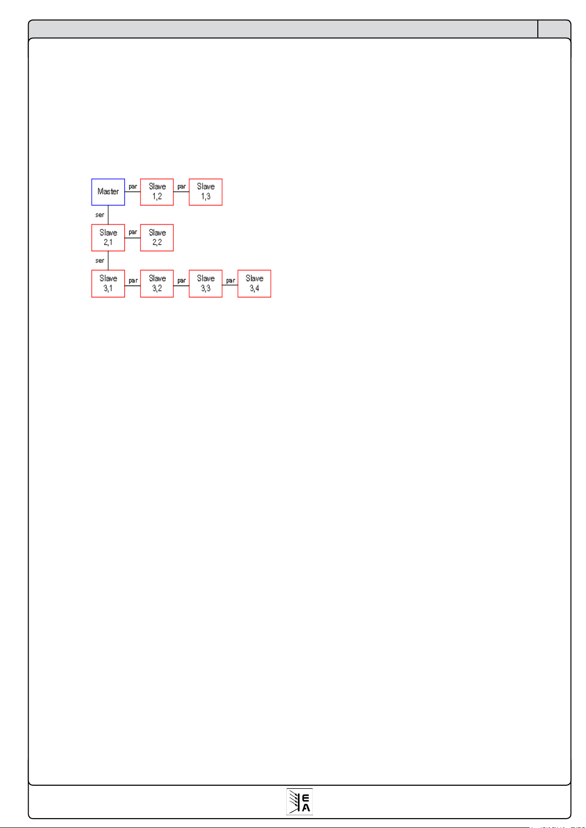
43
© 2007, Elektro-Automatik GmbH & Co. KG
EN
About the interface cards
parallel Default: 1
={1..30} Set the position of the device in the system.
Example: one slave device is connected in serial to the master and three additional slaves are connected in parallel to
that one slave. Those four devices in parallel have to be set
to 2 for the value serial and to 1...4 for the value parallel.
Also see the figure for another example:
Attention! The position serial=1/parallel=1 is dedicated
to the master and may not be set for a slave unit, which
won’t accept it anyway.
The SIO2 port also requires a termination if the slave unit is
at the end (one of the two ports is left blank). The termination
is set with this parameter:
bus terminate Default: NO
= NO No termination.
= YES The SIO2 is terminated
.
7. Communication in detail
7.1 Terms explained
Telegram: Chain of bytes, with varying length. Is either sent
to the device or received from it.
Singlecast: Request or simple message to a single unit. If
devices are linked in a chain, like for instance at CAN, this
telegram is received by all units, but only accepted by the
adressed one. Only related to CAN.
Broadcast: Request or simple message to all units. This
means any unit connected to the PC, no matter if by USB,
CAN or RS232, is receiving this message at once. Only
related to CAN.
Multicast: similiar to broadcast, but only for a certain group
of units, address by the relocatable identifier (RID). Only
related to CAN.
Object: with its properties it describes the object address
and initiates defined reactions at the target unit.
Message: CAN specific data packet
7.2 Prologue
The communication protocol with its object orientated telegram structure is very complex. It is thus recommmended
to use the ready-made LabView components, if possible.
The integration into other environments like Visual Basic, C
or .NET requires programming knowledge about the setup
and use of hardware interfaces like CAN or USB and the
adressing of its drivers. Here we only explain the structure of
the data packet (the telegram) and not how it is transmitted
correctly.
7.3 General notes about the communication
The firmware of the different types of devices is programmed
to consider any circumstances, as far as possible, that may
occur when controlling multiple units at once. Thus it is not
always possible to perform any action at any time and any
state of the device. For example, the data of the function
manager of the series PSI 9000 (see user instruction manual)
is only transmittable in standby state of the unit. Else an error
message would be returned, which is pointing the user to
the fact that the device is not in standby mode.
7.4 About the USB driver
The manufacturer of the USB-Chip on the IF-U1 card offers
two seperate drivers for Windows 98/ME, which are combined in one driver on Windows XP/2003/Vista. One of them
is a genuine USB driver, the other one creates a virtual serial
COM port (VCP) for every USB card, that is connected. While
using LabView to create custom applications, you need to
choose which driver you want to install on Win98/ME. If the
VCP driver is used and thus the COM port, you need to
place the RS232 communication VI for the USB card (on
LabView).
The implementation of the VCP driver is easier, but this driver
is more susceptible to communication problems and errors.
It also creates a new COM port for every USB card, which
complicates the port management and disables plug‘n‘play.
The USB driver requires the user to create own routines,
which handle the USB low level communication, in order to

44
© 2007, Elektro-Automatik GmbH & Co. KG
EN
About the interface cards
ensure the proper transport of the communication data of
our system. These routines are not offered by us. Sample
code is available on the web site of the vendor FTDI, at www.
ftdichip.com. The USB chip is named FT232B
7.5 Structure of the communication
The communication with the controlled units is based on
these telegram types:
a) Simple message: an object is sent, which shall for instance
set the output voltage. As long as this action is permitted by
the current state of the device, the object is accepted and
executed. The device won’t send any answer. If it’s not permitted it will send an answer, an error message.
b) Request: a request is sent by using a certain object, for
instance „get actual values“, and an answer is expected. If
the request is permitted for the current state of the device
it is executed and answered. The answer contains the requested data. If not permitted it will send an error message
as answer.
c) Event: is an error message, which is sent by the device
without request, for example if the access to an object is not
permitted or if the previous message was not recognized by
any reason, like if it was crippled by external interferences.
Contains an error code.
7.6 Telegram structure IF-R1 and IF-U1
The interface cards IF-R1 and IF-U1 are using the same
telegram structure, the one of the CAN card IF-C1 is different. Read below if you‘re using a IF-C1 card. At the serial
transmission of one byte with the RS232 card following bits
are sent:
Start bit + 8 Data bits + Parity bit + Stop bit
The parity is checked for odd.
The USB card is internally working with the RS232 charac-
teristic For both card types it is required to set at least these
transmission parameters for the particular driver:
Baud rate: 57600kBd
Parity: odd
Stop bits: 1
The telegram is structured like this
SD+DN+OBJ+Data+CS
and is built by these bytes:
Byte 0: SD (start delimiter)
The start delimiter determines how to handle the telegram
furthermore. Meaning of the bits:
Bits 0-3
Denethedatalength-1ofthedatainthetelegram.
At an request the data length of the expected data is
given here.
Bit 4
0= Telegram from device to control unit
1= Telegram from control unit to device
Bit 5
0=
Singlecast, telegram to a certain device node
1= Broadcast/Multicast, telegram to all device nodes
Bits 6+7
00 = Reserved
01 = Request for data
10 = Answer to a request
11 = Send data (without previous request)*
* can also occur from the device
Byte 1: DN (device node)
The device node identifies and adresses devices inside a
bus system. Each node number must only be assigned once.
This is used to address a particular device.
Value range: 1...30, others are invalid.
Byte 2: OBJ
The communication objects for a device are addressed by
this byte. In the communications object list (see section 9)
the objects and its function(s) are explained in detail.
Byte 3 - 18: Data field
The data field can be 1-16 bytes long, hence the length of
the telegram varies. If a request is sent (PC -> device) and
no data is sent, the data range is not used and the checksum
of the telegram (see below) follows directly at byte 3. Only if
an answer (device -> PC)is sent, even if it is an event, there
will be data of a specific length.
Word x: CS (check sum)
The check sum is always located at the end of the telegram.
It is built by the simple addition of all bytes of the telegram.
It is two bytes long. The high byte is placed before the low
byte (Big Endian Order).
Example of a telegram:
Object no. 71 (request actual values) shall be sent to a device with device node 1. The telegram has to look like this
(hexadecimal values):
55 01 47 00 9D
The expected answer could look like this:
85 01 47 64 00 1E 00 50 00 01 9F
(this results in 80V, 30A and 2400W at a 80V, 100A and
3000W power supply, like for example the PSI9080-100)
Also see next section for the conversion of set values and
actual values.
More examples in section 9.
45
© 2007, Elektro-Automatik GmbH & Co. KG
EN
About the interface cards
7.6.1 Translating set values and actual values
The set values and actual values (see communication object
list) are, with a few exceptions, transmitted as percentage
values, whereas 0x6400 corresponds to 100%. If a device
has a nominal voltage of 80V and the requested actual
value is 0x3200 (0x32 = 50 = 50%) then it corresponds to
40V output voltage.
The high byte is the percentage number (0x64 = decimal
100) and the low byte is the decimal place of it. You need
to convert the outgoing set values and the incoming actual
values before they can be used.
Nom. value * Percentage act. value
Actual value =
25600
Example: Nom. value of the device is 80V, the percentage actual value
came in as 0x2454. It results in: Actual value = (80 * 9300) / 25600 =
29.06V.
25600 * Set value
Percentage set value =
Nom. value of the device
Example: the set value for voltage shall be 25.36V, the nom. value of the
device is 80V. With the formula it results in:
Percentage set value = (25600 * 25.36) / 80 = 8115 = 0x1FB3.
You need to, of course, round the decimal value for the hex value.
7.7 Message structure for the IF-C1
The interface card IF-C1 supports the CAN V2.0a standard.
The extended address format is not used.
The CAN driver chip needs the identifier, up to 8 data bytes
and the data length for a transmission. The identifier is 11
bits long (CAN 2.0a) and specified by the device node, the
relocatable identifier segment (RID) and the type of the
message. For every unit we define two identifiers (see also
section 4.3.1):
[RID*64 + device node * 2] and
[RID*64 + device node * 2 + 1],
whereas the first identifier is used for „send only“ messages
and the second one (+1) for request messages.
A message can contain a maximum of 8 bytes. The first byte
is the number of the communication object. After this you can
put up to 7 data bytes (see communication object list).
In order to send an object with a 16 bytes long data field
it is thus required to send at least three message and the
data field has to be split up over those three messages. See
below for more.
The data length is only related to the telegram that is about
to be sent (or received) next. In a CAN telegram there are
basically up to 8 bytes transmittable. See also the section
about split telegrams.
Two examples:
a) the device has to be set to remote mode. This is required
to control the device by a status command or to set values.
The device node was set to 15 and the RID to 3. The message is of „send only“ type. The identifier calculates as 3
* 64 + 15 * 2 = 222D or 0xDE. after to the above formula.
According to the object list in section 9 we use object 54
(hex: 0x36) with the data bytes 0x10 (mask) and 0x10 (set
remote). The resulting data length is 3. The CAN message
has to be like this:
ID DL DATA
DE 03 36 10 10
In case you don‘t want to set the state, but request it, the
identifier 0xDF is used (request type, +1) and because it is a
request, the object alone is sufficient as data. The resulting
CAN message would look like this:
ID DL DATA
DF 01 36
7.7.1 Split messages
A split message is a message, which is split into multiple
messages (only possible for objects in „string“ format). After
the object number (=object address) an extra identifier is
inserted. The extra identifier of the first message is 0xFF,
for the second message it is 0xFE and 0xFD for the third
one. The order of these messages is not specified. The
telegram has to be composed again later from these messages. When using the gateway function the split telegrams
are not composed by the gateway. This has to be done by
a superior control unit.
7.7.2 Timing of messages
Singlecast :
After every request the device typically needs 5ms and
maximally 50ms for the answer. Basically you are allowed
to send requests directly after another. But if an event was
received it is required to wait at least 50ms. A time of 100
ms is recommended in order to not slow down the device’s
operation by too heavy communication.
When using the gateway function you need to consider the
time that will be consumed by transferring the telegram from
one bus system to the other. The answer may be delayed
up to 200ms here.
After receiving an error message over this gateway you
should consider to wait at least 100ms until the next transmission.

46
© 2007, Elektro-Automatik GmbH & Co. KG
EN
LabView support
8. Utilities for the communication
8.1 Overview about the Labview VIs
For an easy integration of multiple and even different devices into existing LabView applications we provide a set of
Labview VIs.
Those virtual instruments (VI) enable a simple implementation into and the programming of an application without
the need for the user to learn about the lower levels of
communication.
In order to use the functionality of these VIs it is required to
use and run the software development tool LabView from
the company National Instruments. The LabView VIs support
the use in version 6.1 or higher.
Following minimum system requirements have to be
considered:
- Pentium 3 CPU with 256 MB memory
- Windows operating system (Win98 and WinXP)
Updates of these VIs can be downloaded from our website
www.elektroautomatik.de, sofern verfügbar.
To install and use the VIs in LabView in your environment,
please read the file „installation_english.pdf“ on the included
CD for instructions.
After the installation you can find the VIs in the context menu
of the LabView IDE in „Instrument I/O -> Instrument drivers
-> EA“.
Some VIs are only for devices of series PSI9000 and will only
work with these. They got the token PSI9 in front of their file
name and also in their VI icons. Other VIs are only for the
electronic loads of the series EL3000 and EL9000. These
use the token EL in front of their names and in their icons.
Use and funktionality is described in the user instruction
manual for the VIs. You can access this in the usual way via
the LabView context help or directly from the CD in the folder
\software\labview\. Depecnding on the Windows version it
can be necessary to copy the help file to a local hard drive
in order to read it correctly.
We distinguish three categories of VIs :
1. Communication VIs
2. Standard VIs
3. Special VIs
Important! Always use the proper VIs for your device.
Pleasereadthe LabView VIs helple ontheincluded
CD in order to get an overview and a clue about the
handling.
Broadcast:
After every broadcast request all bus sharing units can only
answer consecutively. Depending on the bys system, the
baud rate and the number of units, as well as the extra bus
traffic the answers can be delayed more or less. The time is
not specifiable and can only be estimated by the formula bus
sharing units * response time at singlecast. In most cases
the response time will be shorter.

47
© 2007, Elektro-Automatik GmbH & Co. KG
EN
- set_mode.vi
Sets the device mode regarding external control and standby
of the device’s output/input. There are two bits, „Standby“
and „Remote“. Standby switches the power output (or input)
of the device on or off. „Remote“ sets the device into remote
mode. The remote mode is required to control the device,
i.e. to set values or transfer data. Without the remote mode
activated the device can only be requested to send actual
values or status data.
The remote mode can only be activated if the device „allows“
it. This depends on the current mode it is in. The local mode
or another, special state or operation mode the device may
inhibit the activation.
- wr_set_values.vi
Writes the set values for U/I/P/R, according to the device type
and if remote mode is enabled. It does not send and set all
four values at once, it sends every value with its own object. If
a set value isn’t given or does not change, the corresponding
object is not sent. The input values are automatically limited
to the device properties. Too high values are set down to the
nominal value of the device. This VI sends simple message
and thus no answer is generated.
- actual_values.vi
Requests the actual values for U, I and P. These are ans-
wered all at once, so it’s very fast. Those values always lie
within the limits of the device and should be identical to the
values displayed on the device itself.
LabView support
8.1.1 Short info Communication VIs
The communication VIs serve as a sort of drivers for the
various bys systems, respectively interface types. These VIs
are the basis of the standard VIs. Without the communication running in the background no device can be addressed.
Hence you must use the communication VIs and start them
before any standard VI is used. Every type of interface uses
its own VI. This is just an overview about the communication
VIs, detailed information about every VI can be found in the
user instruction manual of the VI set.
- CAN.vi
Read/write communication objects with the CAN protocol
with card IF-C1.
- RS232.vi
Read/write communication objects over RS232 (serial COM
port) with card IF-R1.
- USB.vi
Read/write communication objects over USB with card IF-
U1.
- Communication_layer.vi
Core VI of the communication, uses the other three VIs
alternatively, single or combined.
With the VIs „RS232“ and „USB“ you can control up to 29
further devices if the device, which is connected to the PC,
is configured as gateway to the CAN bus (see „4.3 CAN card
IF-C1“). The gateway feature is only recommended with low
bus traffic. The direct communication with the CAN bus from
a master device (PC) is much more efficient and faster. This
but requires an extra CAN master card in the PC.
8.1.2 Short info Standard VIs
The standard VIs are the most used VIs and are adapted to
every different type of device to suit all of its features. You
can control and configure nearly any feature of the particular
device. You can use (place) them as often as you want, but it
is only allowed to run multiple VIs at once if they all address
a different device.
These VIs require the communication VIs to be set up and
running.
This is just an overview about the communication VIs, detailed information about every VI can be found in the user
instruction manual of the VI set.
- init.vi
It is run once at the start of the whole application, but after the
communication VIs (which it requires to run), and initialises
the device which can be „found“. It reads out all necessary
data that is required for the whole system to work correctly
and handles them over to the other VIs.
48
© 2007, Elektro-Automatik GmbH & Co. KG
EN
9. Guide to program the interface cards
9.1 Explanation of the communication object list
The communication object list is located in section 9.3. This
list is the reference when creating user-defined applications, apart from LabView, which are intended to control the
device(s).
The 1st column contains the object number (=object
address). This number has to be assigned to the byte OBJ
in the telegram.
The 3rd column defines if the object is read only, i.e. it
can only be requested from the device, or if it can also be
written.
The 4th column defines a special access condition of an
object. The execution of these objects additionally depends
on one of the below conditions. If the condition is not given,
the object is not executed and the device will send an answer
which contains an error code. Meaning of the numbers:
1 = The output/input of the device has to be switched off
(The object is only accepted and executed by the device if the power output/input is in standby mode)
2 = Option „Internal resistance“ has to be unlocked*
(The object is only accepted and executed by the device if the option „Internal
resistance“ is unlocked)
3 = Transfer of the function data has to be enabled*
(The object is only accepted and executed by the device if it has been
instructed before, by another object, to receive and set function data)
4 = Function manager activated*
(The object is only accepted and executed by the device if the function
manager has already been activated manually in the device menu or by
another object)
5 = Function manager not activated*
(The object is only accepted and executed by the device if the function
manager is not active)
* only at series PSI 9000
Attention! It is generally required to set the device into
remote mode before sending objects that will change
any value on the device.
The 5th column defines the type of the data in the data field
of the telegram.
The 6th column defines the data length of the data field. At
objects with data type „string“ this byte defines the maximum
length of the string. The string has to be terminated with an
EOL (end of line, =0 ) or it ends after the given number of
bytes. Strings are transmitted in up to three split telegrams
when using CAN. See also „7.5.2 Telegram structure IFC1“.
The 7th column is used to mask out data of type „char“.
The mask (1st data byte) defines which bits may be set or
unset. In the telegram, the first byte of the data field is the
mask and the second byte is the data byte (= char data),
which will be masked by the first byte. It defines the bits that
will be changed
Columns 8 & 9 explain details about the data field.
The time format (where used) is of type „integer“ and
deneslikethis:
0 ... 10000 = 0…10,000s
16384 ... 22383 = 10,00s...59,99s
32768 …36367 = 1min:00s…59,99min
49152 …55151 = 1h:00min…99h:59min
9.2 Approach
The programming of the various device classes, in which the
interface cards are used, always follows the same scheme.
It only differs in number and functionality of the communication objects.
Generally applies:
- Monitoring, that is only requesting actual values and status,
is always possible with the appropriate objects (access
type „read“). The devices don‘t require the remote mode
for this.
- Setting of statuses and set values (controlling) requires the
activation of the remote mode (remote in this case means
that the device is remotely controlled via a digital interface
card)
- the remote mode can be blocked by certain circumstances.
For instance, the explicit local operation (only PSI9000) or
another mode the device is in and which does not allow
remote control. For further details refer to the user instruction guide of your device.
In order to start controlling a device, for example by sending
a set value, you need to
1. activate the remote mode (object 54)
2. send the set value.
The remote mode should be left, if not used any further. As
long as it is active, the device can not operated manually or
only restrictedly. The mode is indicated in the display.
Example 1: Activating the remote via IF-R1/IF-U1
According to the telegram format (also see 7.5), the first byte
is the start delimiter, which depends on the type and direction
of the telegram. Using, for instance, a device address (node)
of 5, the SD will be 0xD2, looking like this in bits:
11 01 00 10
Bits 0...3: 2 = three bytes are sent
Bit 4: 1 = direction from PC
Bit 5: 0 = Singlecast
Bits 6+7: 11 = Send data
...continued
Programming

49
© 2007, Elektro-Automatik GmbH & Co. KG
EN
Programming
Alternatively to the bitwise assembly, this can be simplified
by using hex values. Starting from bits 6 + 7 we get:
SD = Message type + Cast type + Direction + Length
whereas the message type is either
0xC0 Send data or
0x40 Request data
and the cast type is either
0x00 Singlecast or
0x20 Broadcast
and the direction is either
0x10 from PC to the device or
0x00 from device to the PC
and the data length - 1 can be
0x00...0x0F up to 16 bytes of data (at CAN see „7.6.1
Splitted messages“)
Always note, that the data length is defined as number
of bytes to send -1!!!
The address (node) of the contacted device is 5, the object
to use is 54 (in hexadecimal 0x36), the mask for the remote
mode (also see table in section 9.3) is 0x10 and the control
byte for remote mode is also 0x10. Then we get this telegram:
D1 05 36 10 10 01 2C
In order to reverse this command, means deactivation of the
remote mode, you need to send D1 05 36 10 00 01 1C. The
mask stays the same, only the control byte changes.
Example 2: Requesting actual values via CAN card
Using CAN, the start delimiter SD and the check sum CS, are
not used. So we only need the object, according to the table
it is 71 (hex = 0x47), the identifier ID (for calculation example
see section 7.6) and the length of the bytes to send. In a CAN
message, the object is included in the data length, so this
message would have a data length of 1, because we only
send the object that requests the actual values. The device
address (node) is 5, the RID is 8. According to the formula
from section 7.6 the identifier calculates as 8 * 64 + 5 * 2
+1 = 523 (hex = 0x20B). The +1 is because it is a message
of type „request“. We now send one byte to ID 0x20B. The
CAN message has to look like this:
02 0B 01 47
Object 71 (0x47), requests actual values
Data length = 1
Identifier
Attention! This is NOT the bit combination of the CAN
message which is truely sent over the CAN bus. A
CAN controller merges various bits into it and adds a
checksum to it. These are only the bytes that are sent
to the CAN controller unit.
An answer to this request could look like this:
02 0B 06 64 00 0A 00 42 42
Same identifier, data length is 6, because three actual value
if 16 bits size are sent. The actual values are transmitted
as percentage values and need to be translated to real values. See section „7.5.1 Translating values“ for details. For
an EL9080-200 the actual values would translate to 100%
for voltage (=80V), 10% for current (=20A) and 66,66% for
power (=1600W).
The nominal values for power, current and voltage can be
read out from the device with the proper objects and used
to translate the actual values to real values.

50
© 2007, Elektro-Automatik GmbH & Co. KG
EN
Lists
9.3 Communication object list
9.3.1 For devices of the series PSI9000
1 2 3 4 5 6 7 8 9
Objekt / Object
Beschreibung / Description
Zugriff /
Access
Zugriffsbedingung /
Access condition
Datentyp / Data type
Datenlänge /
Data length in Bytes
Maske bei Typ 'char'
/ Mask for type 'char'
Beispiel oder weitere Erkärung / Example or further description
0 Gerätetyp / Device type read only --- string 16 PSI 9080-050+EOL (EOL= End of Line)
1 Geräteseriennummer / Device serial no. read only --- string 16 2006100001+EOL
2 Gerätenennspannung / Nominal voltage read only --- float 4 Unenn / Unom= 80.0 (Floating point number IEEE754 Standard)
3 Gerätenennstrom / Nominal current read only --- float 4 Inenn / Inom= 50.0 (Floating point number IEEE754 Standard)
4 Gerätenennleistung / Nominal power read only --- float 4 Pnenn / Pnom=1500.0 (Floating point number IEEE754 Standard)
5 Max. Innenwiderstand / Max. internal resistance read only --- float 4 Rnenn /Rnom=16.00 (Floating point number IEEE754 Standard)
6 Artikelnummer / Order no. read only --- string 16 15200768+EOL
7 Benutzertext / User text read/write --- string 16 Max. 15 alphanumerische Zeichen / Max. 15 characters +EOL
8 Hersteller / Manufacturer read only --- string 16 EA-VIERSEN +EOL
9 Softwareversion / Software version read only --- string 16 V2.01 09.08.06 +EOL
10 Kartentyp / Interface type Slot A read only --- string 16 IF-R1
11 Seriennummer / Serial no. Slot A read only --- string 16 200610002+EOL
12 Artikelnummer / Order no. Slot A read only --- string 16 33100213+EOL
13 Softwareversion / Software version Slot A read only --- string 16 EOL
14 Kartentyp / Interface type Slot B read only --- string 16 IF-C1
15 Seriennummer / Serial no. Slot B read only --- string 16 200610003+EOL
16 Artikelnummer / Order no. Slot B read only --- string 16 33100214+EOL
17 Softwareversion/ Software version Slot B read only --- string 16 V2.01 09.08.06 +EOL
18 2. Softwareversion / 2nd software version read only --- string 16 EOL
19 Geräteklasse / Device class read only --- integer 2 1 = PSI9000; 2 = EL3000 / 9000
20 Speichern von Profilen / Save and load of profiles read/write 1 char 2 0x37
Bit 0..4:
:
Bit 5:
Bit 6:
Bit 7:
Auswahl der Profilnummern / Select profile no.
0 = default; 1 = Profile 1; 2 = Profile 2; 3 = Profile 3; 4 = Profile 4
Lade gewähltes Profil / Load selected profile (1...4)
Speichern des akt. Profils nach Platz x / Save current profile to memory x
Vorgang noch nicht beendet / Profile load/save are busy
21 Freigabe Sollwertsatz / Enable preset list no. read/write 1 char 2 0x0F
Bit 0:
Bit 1:
Bit 2:
Bit 3:
Sollwertsatz 1 ist freigegeben / Preset list no. 1 is enabled Sollwertsatz 2
ist freigegeben / Preset list no. 2 is enabled Sollwertsatz 3 ist
freigegeben / Preset list no. 3 is enabled Sollwertsatz 4 ist freigegeben /
Preset list no. 4 is enabled
22 Sollwertsatz [0] / Preset list [0] U+I read/write 1 integer 4
23 Sollwertsatz [1] / Preset list [1] U+I read/write 1 integer 4
24 Sollwertsatz [2] / Preset list [1] U+I read/write 1 integer 4
25 Sollwertsatz [3] / Preset list [1] U+I read/write 1 integer 4
26 Sollwertsatz [0] / Preset list [0] P+R read/write 1 integer 4
27 Sollwertsatz [1] / Preset list [1] P+R read/write 1 integer 4
28 Sollwertsatz [2] / Preset list [1] P+R read/write 1 integer 4
29 Sollwertsatz [3] / Preset list [1] P+R read/write 1 integer 4
30 Max. einstellbare Spg. / Max. adjustable voltage read/write 1 integer 2 Spannungsgrenze (% von Unenn* 256) / Voltage limit (% of Unom* 256)
31 Min. einstellbare Spg. / Min. adjustable voltage read/write 1 integer 2 Spannungsgrenze (% von Unenn* 256) / Voltage limit (% of Unom* 256)
32 Max. einstellbarer Strom / Max. adjustable current read/write 1 integer 2 Stromgrenze (% von Inenn* 256) / Current limit (% of Inom*256)
33 Min. einstellbarer Strom / Min. adjustable current read/write 1 integer 2 Stromgrenze (% von Inenn* 256) / Current limit (% of Inom*256)
34 Max. einstellbare Leistung / Max. adjustable power read/write 1 integer 2 Leistungsgrenze (% von Pnenn*256) / Power limit (% of Pnom *256)
35 Max. einstellb. Widerstand/ Max. adj. resistance read/write 1+2 integer 2 Innenwiderstandsgrenze(% von Rnenn *256) / Resistance limit (% of Rnom *256)
36 Profileinstellungen / Profile settings read/write 1 char 2 0xDF
Bit 0+1:
:
Bit 3 :
:
Bit 4:
:
Bit 6+7:
:
:
Betriebsart / Set operation mode
00 = U/I/P mode 01 = U/I/R
Übertemperaturabschaltung / Reaction after overtemperature
0= OT Alarm disappear: OFF; 1= OT Alarm disappear: Auto ON
Netzwiederkehr / Reaction after power-on
0= Power ON: OFF , 1= Power ON = auto ON
Einstellvarianten von Sollwerten / Mode for set values
00 = direct adjust of set value; 01 = adjust set value with return
10 = set value via preset list
37
38 OVP Grenze / OVP threshold read/write 1 integer 2 Spannungswert (% von Unenn* 256) / Voltage value (% of Unom* 256)
39 Überspannungsgrenze +Zeit / U> threshold +time read/write 1 integer 4
40 Unterspannungsgrenze + Zeit / U< threshold +time read/write 1 integer 4
41
42 Überstromgrenze +Zeit / I> threshold +time read/write 1 integer 4
43 Unterstromgrenze+Zeit / I< threshold +time read/write 1 integer 4
44 Überwachung U / Supervise U settings read/write 1 char 2 0x33
Bit 1+2: U>
Bit 4+5: U<
00=keine / none; 01= nur Anzeige / indicate only
10=Warnung / Warning; 11 = Alarm
45 Überwachung I / Supervise I settings read/write 1 char 2 0x33
Bit 1+2: I>
Bit 4+5: I<
00=keine / none; 01= nur Anzeige / indicate only
10=Warnung / Warning; 11 = Alarm
46 Überwachung Soll-Istvergleich/ Supervise step resp. settings read/write 1 char 2 0x33
Bit 1+2:
:
Bit 4+5:
00=keine / none; 01= nur Anzeige / indicate only
10=Warnung / Warning; 11 = Alarm
00=dU; 01=di; 10= dP
47
Soll-Istvergleich Toleranz+Zeit / Set-act. comparison tolerance
+ time
read/write 1 integer 6
Word 0:
Word 1: Tsr
Word 2: Tsf
Toleranz (% von Nennwert* 256) / Tolerance ( % of nom. value* 256)
Zeit / Time (siehe Zeitformat/ see format of time values)
Zeit / Time (siehe Zeitformat/ see format of time values)
48
49
50 Sollwert U / Set value U read/write --- integer 2 Spannungswert (% von Unenn* 256) / Voltage value (% of Unom* 256)
51 Sollwert I / Set value I read/write --- integer 2 Stromwert (% von Inenn* 256)/ Current value (% of Inom*256)
52 Sollwert P / Set value P read/write --- integer 2 Leistungsangabe (% von Pnenn*256) / Power value (% of Pnom *256)
53
Sollwert R / Set value R **** EL_MMI: Sollwert A für R1
Bereich / Set value A for R1 range
read/write 2 integer 2 Innenwiderstand (% von Rnenn *256) / Resistance (% of Rnom *256)
54 Steuerung des Netzteils / Power supply control read/write --- char 2 0x51
Bit 0:
Bit 3:
Bit 4:
Bit 6:
Netzteilausgang eingeschaltet / Output is switched on
Pmax reduziert bei Netzunterspg. / P reduced at mains undervoltage
Setzt in Fernbetriebmodus / Sets into remote state
Funktionsmanager in Betrieb/ Function manager active
55
56 Steuerung des Funktionsman. / Control of function manager read/write 4 char 2 0xFF
Bit 0: ESC
Bit 0: NEW
Bit 1: STEP
Bit 3: STOP
Bit 4: RUN+GO
Ext. Bedienung des Funktionsman. / External control of the function man.
Verlasse Funktiosmanager / Leave function manager mode
Setzt den Fkt.-gen.auf den Startpunkt zurück / Reset fct. man. to start
Führt den nächsten Seq.punkt aus / Proceed to the next seq.-point
Hält den laufenden Fkt.man. an/ Halt the function manager
Startet den Funktionsmanager / Start the function manager
Word 0:
Word 1:
Word 0:
Word 1:
Leistungssollwert (% von Pnenn*256) / Set power (% of Pnom *256)
Innenwiderstand(% von Rnenn *256) / Set resistance (% of Rnom *256)
Word 0:
Word 1:
Word 0:
Word 1:
Spgs.-Sollwert (% von Unenn* 256) / Set voltage ( % of Unom* 256)
Stromsollwert (% von Inenn* 256) / Set current (% of Inom*256)
Spannungswert (% von Unenn* 256) / Voltage value (% of Unom* 256)
Zeit / Time (siehe Zeitformat / see format of time values)
Stromwert (% von Inenn* 256) / Current value(% of Inom* 256)
Zeit / Time (siehe Zeitformat/ see format of time values)

51
© 2007, Elektro-Automatik GmbH & Co. KG
EN
Lists
1 2 3 4 5 6 7 8 9
Beschreibung / Description
Zugriff /
Access
Zugriffsbedingung /
Access condition
Datenlänge /
Data length in Bytes
Maske bei Typ 'char'
/ Mask for type 'char'
Beispiel oder weitere Erkärung / Example or further description
0 Gerätetyp / Device type read only --- string 16 PSI 9080-050+EOL (EOL= End of Line)
1 Geräteseriennummer / Device serial no. read only --- string 16 2006100001+EOL
2 Gerätenennspannung / Nominal voltage read only --- float 4 Unenn / Unom= 80.0 (Floating point number IEEE754 Standard)
3 Gerätenennstrom / Nominal current read only --- float 4 Inenn / Inom= 50.0 (Floating point number IEEE754 Standard)
4 Gerätenennleistung / Nominal power read only --- float 4 Pnenn / Pnom=1500.0 (Floating point number IEEE754 Standard)
5 Max. Innenwiderstand / Max. internal resistance read only --- float 4 Rnenn /Rnom=16.00 (Floating point number IEEE754 Standard)
6 Artikelnummer / Order no. read only --- string 16 15200768+EOL
7 Benutzertext / User text read/write --- string 16 Max. 15 alphanumerische Zeichen / Max. 15 characters +EOL
8 Hersteller / Manufacturer read only --- string 16 EA-VIERSEN +EOL
9 Softwareversion / Software version read only --- string 16 V2.01 09.08.06 +EOL
10 Kartentyp / Interface type Slot A read only --- string 16 IF-R1
11 Seriennummer / Serial no. Slot A read only --- string 16 200610002+EOL
12 Artikelnummer / Order no. Slot A read only --- string 16 33100213+EOL
13 Softwareversion / Software version Slot A read only --- string 16 EOL
14 Kartentyp / Interface type Slot B read only --- string 16 IF-C1
15 Seriennummer / Serial no. Slot B read only --- string 16 200610003+EOL
16 Artikelnummer / Order no. Slot B read only --- string 16 33100214+EOL
17 Softwareversion/ Software version Slot B read only --- string 16 V2.01 09.08.06 +EOL
18 2. Softwareversion / 2nd software version read only --- string 16 EOL
19 Geräteklasse / Device class read only --- integer 2 1 = PSI9000; 2 = EL3000 / 9000
20 Speichern von Profilen / Save and load of profiles read/write 1 char 2 0x37
Bit 0..4:
:
Bit 5:
Bit 6:
Bit 7:
Auswahl der Profilnummern / Select profile no.
0 = default; 1 = Profile 1; 2 = Profile 2; 3 = Profile 3; 4 = Profile 4
Lade gewähltes Profil / Load selected profile (1...4)
Speichern des akt. Profils nach Platz x / Save current profile to memory x
Vorgang noch nicht beendet / Profile load/save are busy
21 Freigabe Sollwertsatz / Enable preset list no. read/write 1 char 2 0x0F
Bit 0:
Bit 1:
Bit 2:
Bit 3:
Sollwertsatz 1 ist freigegeben / Preset list no. 1 is enabled Sollwertsatz 2
ist freigegeben / Preset list no. 2 is enabled Sollwertsatz 3 ist
freigegeben / Preset list no. 3 is enabled Sollwertsatz 4 ist freigegeben /
Preset list no. 4 is enabled
22 Sollwertsatz [0] / Preset list [0] U+I read/write 1 integer 4
23 Sollwertsatz [1] / Preset list [1] U+I read/write 1 integer 4
24 Sollwertsatz [2] / Preset list [1] U+I read/write 1 integer 4
25 Sollwertsatz [3] / Preset list [1] U+I read/write 1 integer 4
26 Sollwertsatz [0] / Preset list [0] P+R read/write 1 integer 4
27 Sollwertsatz [1] / Preset list [1] P+R read/write 1 integer 4
28 Sollwertsatz [2] / Preset list [1] P+R read/write 1 integer 4
29 Sollwertsatz [3] / Preset list [1] P+R read/write 1 integer 4
30 Max. einstellbare Spg. / Max. adjustable voltage read/write 1 integer 2 Spannungsgrenze (% von Unenn* 256) / Voltage limit (% of Unom* 256)
31 Min. einstellbare Spg. / Min. adjustable voltage read/write 1 integer 2 Spannungsgrenze (% von Unenn* 256) / Voltage limit (% of Unom* 256)
32 Max. einstellbarer Strom / Max. adjustable current read/write 1 integer 2 Stromgrenze (% von Inenn* 256) / Current limit (% of Inom*256)
33 Min. einstellbarer Strom / Min. adjustable current read/write 1 integer 2 Stromgrenze (% von Inenn* 256) / Current limit (% of Inom*256)
34 Max. einstellbare Leistung / Max. adjustable power read/write 1 integer 2 Leistungsgrenze (% von Pnenn*256) / Power limit (% of Pnom *256)
35 Max. einstellb. Widerstand/ Max. adj. resistance read/write 1+2 integer 2 Innenwiderstandsgrenze(% von Rnenn *256) / Resistance limit (% of Rnom *256)
36 Profileinstellungen / Profile settings read/write 1 char 2 0xDF
Bit 0+1:
:
Bit 3 :
:
Bit 4:
:
Bit 6+7:
:
:
Betriebsart / Set operation mode
00 = U/I/P mode 01 = U/I/R
Übertemperaturabschaltung / Reaction after overtemperature
0= OT Alarm disappear: OFF; 1= OT Alarm disappear: Auto ON
Netzwiederkehr / Reaction after power-on
0= Power ON: OFF , 1= Power ON = auto ON
Einstellvarianten von Sollwerten / Mode for set values
00 = direct adjust of set value; 01 = adjust set value with return
10 = set value via preset list
37
38 OVP Grenze / OVP threshold read/write 1 integer 2 Spannungswert (% von Unenn* 256) / Voltage value (% of Unom* 256)
39 Überspannungsgrenze +Zeit / U> threshold +time read/write 1 integer 4
40 Unterspannungsgrenze + Zeit / U< threshold +time read/write 1 integer 4
41
42 Überstromgrenze +Zeit / I> threshold +time read/write 1 integer 4
43 Unterstromgrenze+Zeit / I< threshold +time read/write 1 integer 4
44 Überwachung U / Supervise U settings read/write 1 char 2 0x33
Bit 1+2: U>
Bit 4+5: U<
00=keine / none; 01= nur Anzeige / indicate only
10=Warnung / Warning; 11 = Alarm
45 Überwachung I / Supervise I settings read/write 1 char 2 0x33
Bit 1+2: I>
Bit 4+5: I<
00=keine / none; 01= nur Anzeige / indicate only
10=Warnung / Warning; 11 = Alarm
46 Überwachung Soll-Istvergleich/ Supervise step resp. settings read/write 1 char 2 0x33
Bit 1+2:
:
Bit 4+5:
00=keine / none; 01= nur Anzeige / indicate only
10=Warnung / Warning; 11 = Alarm
00=dU; 01=di; 10= dP
47
Soll-Istvergleich Toleranz+Zeit / Set-act. comparison tolerance
+ time
read/write 1 integer 6
Word 0:
Word 1: Tsr
Word 2: Tsf
Toleranz (% von Nennwert* 256) / Tolerance ( % of nom. value* 256)
Zeit / Time (siehe Zeitformat/ see format of time values)
Zeit / Time (siehe Zeitformat/ see format of time values)
48
49
50 Sollwert U / Set value U read/write --- integer 2 Spannungswert (% von Unenn* 256) / Voltage value (% of Unom* 256)
51 Sollwert I / Set value I read/write --- integer 2 Stromwert (% von Inenn* 256)/ Current value (% of Inom*256)
52 Sollwert P / Set value P read/write --- integer 2 Leistungsangabe (% von Pnenn*256) / Power value (% of Pnom *256)
53
Sollwert R / Set value R **** EL_MMI: Sollwert A für R1
Bereich / Set value A for R1 range
read/write 2 integer 2 Innenwiderstand (% von Rnenn *256) / Resistance (% of Rnom *256)
54 Steuerung des Netzteils / Power supply control read/write --- char 2 0x51
Bit 0:
Bit 3:
Bit 4:
Bit 6:
Netzteilausgang eingeschaltet / Output is switched on
Pmax reduziert bei Netzunterspg. / P reduced at mains undervoltage
Setzt in Fernbetriebmodus / Sets into remote state
Funktionsmanager in Betrieb/ Function manager active
55
56 Steuerung des Funktionsman. / Control of function manager read/write 4 char 2 0xFF
Bit 0: ESC
Bit 0: NEW
Bit 1: STEP
Bit 3: STOP
Bit 4: RUN+GO
Ext. Bedienung des Funktionsman. / External control of the function man.
Verlasse Funktiosmanager / Leave function manager mode
Setzt den Fkt.-gen.auf den Startpunkt zurück / Reset fct. man. to start
Führt den nächsten Seq.punkt aus / Proceed to the next seq.-point
Hält den laufenden Fkt.man. an/ Halt the function manager
Startet den Funktionsmanager / Start the function manager
1 2 3 4 5 6 7 8 9
Objekt / Object
Beschreibung / Description
Zugriff /
Access
Zugriffsbedingung /
Access condition
Datentyp / Data type
Datenlänge /
Data length in Bytes
Maske bei Typ 'char' /
Mask for type 'char'
Beispiel oder weitere Erkärung / Example or further description
57
58 Stoppunkt der Funktion / Stop point of function read/write 4 integer 4
Byte 1:
Byte 2:
Byte 3:
Byte 4:
1 = Stoppunktfunktion aktiv setzen / Set stop point active
Stopp nach x Wiederholungen d. Funktion / Stop after x repetitions of fct
Stopp nach xWiederholungen der Sequenz / Stop after x repetitions of seq.
High nibble: Seq.nr. / Seq. no.; Low nibble: Seq.-punkt / Seq. point
59
60
61
62
63
64
65
66
67
68
69
70 Gerätezustand / Device state read only --- integer 2
Bit 0+1:
Bit 2:
Bit 3:
Bit 5:
Bit 6:
Bit 7:
Bit 8:
Bit 9+10:
Bit 11:
Bit 12:
Bit 13:
Bit 15:
Gerätezustand abfragen / Query device state
00 = freier Zugriff / free access; 01= Remote; 10= External; 11=Local
1 = System Link Mode aktiv / active
System Link Mode: 0 = Master; 1 = Slave
1 = über IF-Ax gesteuert / Controlled by IF-Ax
1 = Funktionsmanager aktiv / Function manager active
1 = Menü aktiv / Menu active
1 = Ausgang eingeschaltet / Output on
Reglerstatus / controller state: 00=CV; 01=CR; 10= CC; 11= CP
1 = Leistungsreduktion / Power is reduced
1 = Alarm aktiv / Alarm active
1 = "Auto On" (Ausgang einschaltbereit) / "Auto On" state unlocked
1 = alle Slaves sind online / all slaves are online
71 Istwerte / Actual values read only --- integer 6
Word 0:
Word 1:
Word 2:
Spannungswert (% von Unenn* 256) / Voltage value (% of Unom* 256) Stromwert
(% von Inenn* 256) / Current value (% of Inom*256) Leistungsangabe (% von
Pnenn*256) / Power value (% of Pnom *256)
72 Aktuelle Sollwerte / Momentary set values read only --- integer 6
Word 0:
Word 1:
Word 2:
Spannungswert (% von Unenn* 256) / Voltage value (% of Unom* 256) Stromwert
(% von Inenn* 256) / Current value (% of Inom*256) Leistungsangabe (% von
Pnenn*256) / Power value (% of Pnom *256)
73 Istwert U+I mit Zeitstempel / Actual values U+I with time stamp read only --- integer 6
Word 0:
Word 1:
Word 2:
Spannungswert (% von Unenn* 256) / Voltage value (% of Unom* 256)
Stromwert (% von Inenn* 256) / Current value (% of Inom*256)
Unterer Teil der Gesamtzeit der laufenden Fkt. (ms) / Lower part of the
total time of running fct. (ms)
74 Status der Funktionssteuerung / State of function control read only 4 char 2 0xFF
Bit 0: NEW
Bit 1: STEP
Bit 2: STOP
Bit 3: RUN
Funktionsablauf am Start / Function flow is at the starting point
Abarbeitung eines Sequenzpunktes / Execute until next point
Funktionsablauf wurde angehalten / Function flow stopped
Funktionsmanager läuft / Function manager is running
75 Status des Funktionsablaufs / State of the executed function read only 4 integer 6
Byte 0:
Byte 1:
Byte 2:
Byte 3:
Word 2:
= Wert von Objekt 74 / Value of object 74
bisherige Wiederholungen der Funktion / Repetitions of current function
bisherige Wiederholungen der Sequenz / Repetitions of current sequence
Highnibble: Seq.nr. / Seq. no.; Lownibble: Seq.-punkt / Seq. point
Unterer Teil der Gesamtzeit der laufenden Fkt. (ms) / Lower part of the
total time of running fct.(ms)
76 Temperaturwert / Temperature value read only --- integer 6
Word 0:
Word 1:
Word 2:
1. Leistungsteil: Temp. (°C*256) / 1st power stage: temp. (°C*256)
2. Leistungsteil: Temp. (°C*256) / 2nd power stage: temp. (°C*256)
3. Leistungsteil: Temp. (°C*256) / 3rd power stage: temp. (°C*256)
77 Meldungen des Gerätes / Device notifications read only --- integer 6
Byte 0:
Byte 1:
Byte 2:
Byte 3:
Byte 4:
Byte 5:
1. Alarmkategorie / Alarm category
1. Alarmcode
2. Alarmkategorie / Alarm category
2. Alarmcode
3. Alarmkategorie / Alarm category
3. Alarmcode
(siehe Alarmcodetabelle / see alarm code table)
78 Absolute Zeit des Fkt-Ablaufs / Total time of executed fct. read only 4 integer 4 Gesamtzeit der laufenden Fkt.(ms) / Total time of running fct.(ms)
79
80 Einstellungen SIO2 / Setup SIO2 read only --- char 2 0 Bit: 5+6
00 oder / or 01 = System Link Mode nicht eingestellt / not activated
10= System Link Mode: Gerät ist Slave / Device is slave
11= System Link Mode: Gerät ist Master / Device is master
81 System Link Konfiguration / System Link configuration read only --- char 2 0
Bit: 0…4
Bit: 5...7
Anzahl der parallelen Geräte / Number of parallel devices
Anzahl der Reihenschaltung / Number of serial connections
82
83
84
85
86
87
88
89
90 Abspeichern des Funktionsablaufs/ Storage of function read/write 1+5 char 2 0x25
Bit: 0
Bit: 2
Bit: 4
Bit: 5
Bit: 6
Freigabe zur Übertragung / Enable transmission of function data
Speichere Daten des Funktionsablaufs / Save function data
Gerät im Funktionsmanagerbetrieb / Device in function manager mode
Wechsle in den Funktionsmanager / Switch to function manager
Funktionsmanager blockiert / Function manager blocked
91 Funktionsablauf konfigurieren / Setup of function read/write 1+3 integer 6
Byte 0: Bit 0..2
Byte 0: Bit 4..6
Byte 1: Bit 0..2
Byte 1: Bit 4..6
Byte 2: Bit 0..2
Byte 2: Bit 7
Byte 4:
1. abzuarbeitende Seq. (0 bis 4) / 1st sequence (0 to 4) to process in fct.
2. abzuarbeitende Seq. (0 bis 4) / 2nd sequence (0 to 4) to process in fct
3. abzuarbeitende Seq. (0 bis 4) / 3rd sequence (0 to 4) to process in fct.
4. abzuarbeitende Seq. (0 bis 4) / 4th sequence (0 to 4) to process in fct.
5. abzuarbeitende Seq.(0 bis 4) /4th sequence(0 to 4) to process in fct.
0= UIP Mode; 1= UIR Mode ( nur wenn freigeschaltet / only if unlocked)
Wiederholungen des Funktionsablaufs / Repetitions of function
Bereich: 1..255; 255 =unendlich / Range: 1..255; 255= infinite
92 Einstellungen 1.Sequenz / Setup of 1st sequence read/write 1+3 integer 6
93 Einstellungen 2.Sequenz / Setup of 2nd sequence read/write 1+3 integer 6
94 Einstellungen 3.Sequenz / Setup of 3rd sequence read/write 1+3 integer 6
95 Einstellungen 4.Sequenz / Setup of 4th sequence read/write 1+3 integer 6
96 Einstellungen 5.Sequenz / Setup of 5th sequence read/write 1+3 integer 6
97 1.Sequenzpkt. der 1.Seq. / 1st seq.point of 1st sequence read/write 1+3 integer 6
98 2.Sequenzpkt. der 1.Seq. / 2nd seq.point of 1st sequence read/write 1+3 integer 6
99 3.Sequenzpkt. der 1.Seq. / 3rd seq.point of 1st sequence read/write 1+3 integer 6
Word 0:
Word 1:
Word 0:
Word 1:
Word 0:
Word 1:
Word 2:
Word 0:
Word 1:
Word 2:
Leistungssollwert (% von Pnenn*256) / Set power (% of Pnom *256)
Innenwiderstand(% von Rnenn *256) / Set resistance (% of Rnom *256)
Word 0:
Word 1:
Word 0:
Word 1:
Spgs.-Sollwert (% von Unenn* 256) / Set voltage ( % of Unom* 256)
Stromsollwert (% von Inenn* 256) / Set current (% of Inom*256)
Spannungswert (% von Unenn* 256) / Voltage value (% of Unom* 256)
Zeit / Time (siehe Zeitformat / see format of time values)
Stromwert (% von Inenn* 256) / Current value(% of Inom* 256)
Zeit / Time (siehe Zeitformat/ see format of time values)
Leistungsgrenze (% von Pnenn*256) / Power limit (% of Pnom *256)
Innenwiderstand (% von Rnenn *256) / Rresistance (% of Rnom *256)
Wiederholungen der Sequenz / Repetitions of the sequence
Bereich 1..255; 255 =unendlich / Range: 1..255; 255= endless
Spannungswert (% von Unenn* 256) / Voltage value (% of Unom* 256)
Stromwert (% von Inenn* 256) / Current value(% of Inom* 256)
Zeit / Time (siehe Zeitformat / see format of time values)
52
© 2007, Elektro-Automatik GmbH & Co. KG
EN
Lists
Explanations about the communication object list
A detailed description is in section 9.1.
Allvaluesaredecimal,exceptwhengiveninhexadecimalwithprex0x.
Important!
The mask in column 7 has always be put directly after the object number in the telegram and before the data byte(s).
The mask that is given in the list is is a mask for all bits of the byte that are allowed to be changed. If a single bit has to be
changed, a different mask must be used. Example: the main mask is 0x51, which enables the bits 0, 4 and 6. If only bit 0
shall be changed, mask 0x01 has to be used.
The mask is also sent in an answer if an object is requested that, when sent, also requires the use of a mask. The first byte
of data in the answer is the mask, the second byte the requested status byte. The mask has no use here.
1 2 3 4 5 6 7 8 9
Beschreibung / Description
Zugriff /
Access
Zugriffsbedingung /
Access condition
Datenlänge /
Data length in Bytes
Maske bei Typ 'char'
/ Mask for type 'char'
Beispiel oder weitere Erkärung / Example or further description
0 Gerätetyp / Device type read only --- string 16 PSI 9080-050+EOL (EOL= End of Line)
1 Geräteseriennummer / Device serial no. read only --- string 16 2006100001+EOL
2 Gerätenennspannung / Nominal voltage read only --- float 4 Unenn / Unom= 80.0 (Floating point number IEEE754 Standard)
3 Gerätenennstrom / Nominal current read only --- float 4 Inenn / Inom= 50.0 (Floating point number IEEE754 Standard)
4 Gerätenennleistung / Nominal power read only --- float 4 Pnenn / Pnom=1500.0 (Floating point number IEEE754 Standard)
5 Max. Innenwiderstand / Max. internal resistance read only --- float 4 Rnenn /Rnom=16.00 (Floating point number IEEE754 Standard)
6 Artikelnummer / Order no. read only --- string 16 15200768+EOL
7 Benutzertext / User text read/write --- string 16 Max. 15 alphanumerische Zeichen / Max. 15 characters +EOL
8 Hersteller / Manufacturer read only --- string 16 EA-VIERSEN +EOL
9 Softwareversion / Software version read only --- string 16 V2.01 09.08.06 +EOL
10 Kartentyp / Interface type Slot A read only --- string 16 IF-R1
11 Seriennummer / Serial no. Slot A read only --- string 16 200610002+EOL
12 Artikelnummer / Order no. Slot A read only --- string 16 33100213+EOL
13 Softwareversion / Software version Slot A read only --- string 16 EOL
14 Kartentyp / Interface type Slot B read only --- string 16 IF-C1
15 Seriennummer / Serial no. Slot B read only --- string 16 200610003+EOL
16 Artikelnummer / Order no. Slot B read only --- string 16 33100214+EOL
17 Softwareversion/ Software version Slot B read only --- string 16 V2.01 09.08.06 +EOL
18 2. Softwareversion / 2nd software version read only --- string 16 EOL
19 Geräteklasse / Device class read only --- integer 2 1 = PSI9000; 2 = EL3000 / 9000
20 Speichern von Profilen / Save and load of profiles read/write 1 char 2 0x37
Bit 0..4:
:
Bit 5:
Bit 6:
Bit 7:
Auswahl der Profilnummern / Select profile no.
0 = default; 1 = Profile 1; 2 = Profile 2; 3 = Profile 3; 4 = Profile 4
Lade gewähltes Profil / Load selected profile (1...4)
Speichern des akt. Profils nach Platz x / Save current profile to memory x
Vorgang noch nicht beendet / Profile load/save are busy
21 Freigabe Sollwertsatz / Enable preset list no. read/write 1 char 2 0x0F
Bit 0:
Bit 1:
Bit 2:
Bit 3:
Sollwertsatz 1 ist freigegeben / Preset list no. 1 is enabled Sollwertsatz 2
ist freigegeben / Preset list no. 2 is enabled Sollwertsatz 3 ist
freigegeben / Preset list no. 3 is enabled Sollwertsatz 4 ist freigegeben /
Preset list no. 4 is enabled
22 Sollwertsatz [0] / Preset list [0] U+I read/write 1 integer 4
23 Sollwertsatz [1] / Preset list [1] U+I read/write 1 integer 4
24 Sollwertsatz [2] / Preset list [1] U+I read/write 1 integer 4
25 Sollwertsatz [3] / Preset list [1] U+I read/write 1 integer 4
26 Sollwertsatz [0] / Preset list [0] P+R read/write 1 integer 4
27 Sollwertsatz [1] / Preset list [1] P+R read/write 1 integer 4
28 Sollwertsatz [2] / Preset list [1] P+R read/write 1 integer 4
29 Sollwertsatz [3] / Preset list [1] P+R read/write 1 integer 4
30 Max. einstellbare Spg. / Max. adjustable voltage read/write 1 integer 2 Spannungsgrenze (% von Unenn* 256) / Voltage limit (% of Unom* 256)
31 Min. einstellbare Spg. / Min. adjustable voltage read/write 1 integer 2 Spannungsgrenze (% von Unenn* 256) / Voltage limit (% of Unom* 256)
32 Max. einstellbarer Strom / Max. adjustable current read/write 1 integer 2 Stromgrenze (% von Inenn* 256) / Current limit (% of Inom*256)
33 Min. einstellbarer Strom / Min. adjustable current read/write 1 integer 2 Stromgrenze (% von Inenn* 256) / Current limit (% of Inom*256)
34 Max. einstellbare Leistung / Max. adjustable power read/write 1 integer 2 Leistungsgrenze (% von Pnenn*256) / Power limit (% of Pnom *256)
35 Max. einstellb. Widerstand/ Max. adj. resistance read/write 1+2 integer 2 Innenwiderstandsgrenze(% von Rnenn *256) / Resistance limit (% of Rnom *256)
36 Profileinstellungen / Profile settings read/write 1 char 2 0xDF
Bit 0+1:
:
Bit 3 :
:
Bit 4:
:
Bit 6+7:
:
:
Betriebsart / Set operation mode
00 = U/I/P mode 01 = U/I/R
Übertemperaturabschaltung / Reaction after overtemperature
0= OT Alarm disappear: OFF; 1= OT Alarm disappear: Auto ON
Netzwiederkehr / Reaction after power-on
0= Power ON: OFF , 1= Power ON = auto ON
Einstellvarianten von Sollwerten / Mode for set values
00 = direct adjust of set value; 01 = adjust set value with return
10 = set value via preset list
37
38 OVP Grenze / OVP threshold read/write 1 integer 2 Spannungswert (% von Unenn* 256) / Voltage value (% of Unom* 256)
39 Überspannungsgrenze +Zeit / U> threshold +time read/write 1 integer 4
40 Unterspannungsgrenze + Zeit / U< threshold +time read/write 1 integer 4
41
42 Überstromgrenze +Zeit / I> threshold +time read/write 1 integer 4
43 Unterstromgrenze+Zeit / I< threshold +time read/write 1 integer 4
44 Überwachung U / Supervise U settings read/write 1 char 2 0x33
Bit 1+2: U>
Bit 4+5: U<
00=keine / none; 01= nur Anzeige / indicate only
10=Warnung / Warning; 11 = Alarm
45 Überwachung I / Supervise I settings read/write 1 char 2 0x33
Bit 1+2: I>
Bit 4+5: I<
00=keine / none; 01= nur Anzeige / indicate only
10=Warnung / Warning; 11 = Alarm
46 Überwachung Soll-Istvergleich/ Supervise step resp. settings read/write 1 char 2 0x33
Bit 1+2:
:
Bit 4+5:
00=keine / none; 01= nur Anzeige / indicate only
10=Warnung / Warning; 11 = Alarm
00=dU; 01=di; 10= dP
47
Soll-Istvergleich Toleranz+Zeit / Set-act. comparison tolerance
+ time
read/write 1 integer 6
Word 0:
Word 1: Tsr
Word 2: Tsf
Toleranz (% von Nennwert* 256) / Tolerance ( % of nom. value* 256)
Zeit / Time (siehe Zeitformat/ see format of time values)
Zeit / Time (siehe Zeitformat/ see format of time values)
48
49
50 Sollwert U / Set value U read/write --- integer 2 Spannungswert (% von Unenn* 256) / Voltage value (% of Unom* 256)
51 Sollwert I / Set value I read/write --- integer 2 Stromwert (% von Inenn* 256)/ Current value (% of Inom*256)
52 Sollwert P / Set value P read/write --- integer 2 Leistungsangabe (% von Pnenn*256) / Power value (% of Pnom *256)
53
Sollwert R / Set value R **** EL_MMI: Sollwert A für R1
Bereich / Set value A for R1 range
read/write 2 integer 2 Innenwiderstand (% von Rnenn *256) / Resistance (% of Rnom *256)
54 Steuerung des Netzteils / Power supply control read/write --- char 2 0x51
Bit 0:
Bit 3:
Bit 4:
Bit 6:
Netzteilausgang eingeschaltet / Output is switched on
Pmax reduziert bei Netzunterspg. / P reduced at mains undervoltage
Setzt in Fernbetriebmodus / Sets into remote state
Funktionsmanager in Betrieb/ Function manager active
55
56 Steuerung des Funktionsman. / Control of function manager read/write 4 char 2 0xFF
Bit 0: ESC
Bit 0: NEW
Bit 1: STEP
Bit 3: STOP
Bit 4: RUN+GO
Ext. Bedienung des Funktionsman. / External control of the function man.
Verlasse Funktiosmanager / Leave function manager mode
Setzt den Fkt.-gen.auf den Startpunkt zurück / Reset fct. man. to start
Führt den nächsten Seq.punkt aus / Proceed to the next seq.-point
Hält den laufenden Fkt.man. an/ Halt the function manager
Startet den Funktionsmanager / Start the function manager
1 2 3 4 5 6 7 8 9
Beschreibung / Description
Zugriff /
Access
Zugriffsbedingung /
Access condition
Datenlänge /
Data length in Bytes
Maske bei Typ 'char' /
Mask for type 'char'
Beispiel oder weitere Erkärung / Example or further description
57
58 Stoppunkt der Funktion / Stop point of function read/write 4 integer 4
Byte 1:
Byte 2:
Byte 3:
Byte 4:
1 = Stoppunktfunktion aktiv setzen / Set stop point active
Stopp nach x Wiederholungen d. Funktion / Stop after x repetitions of fct
Stopp nach xWiederholungen der Sequenz / Stop after x repetitions of seq.
High nibble: Seq.nr. / Seq. no.; Low nibble: Seq.-punkt / Seq. point
59
60
61
62
63
64
65
66
67
68
69
70 Gerätezustand / Device state read only --- integer 2
Bit 0+1:
Bit 2:
Bit 3:
Bit 5:
Bit 6:
Bit 7:
Bit 8:
Bit 9+10:
Bit 11:
Bit 12:
Bit 13:
Bit 15:
Gerätezustand abfragen / Query device state
00 = freier Zugriff / free access; 01= Remote; 10= External; 11=Local
1 = System Link Mode aktiv / active
System Link Mode: 0 = Master; 1 = Slave
1 = über IF-Ax gesteuert / Controlled by IF-Ax
1 = Funktionsmanager aktiv / Function manager active
1 = Menü aktiv / Menu active
1 = Ausgang eingeschaltet / Output on
Reglerstatus / controller state: 00=CV; 01=CR; 10= CC; 11= CP
1 = Leistungsreduktion / Power is reduced
1 = Alarm aktiv / Alarm active
1 = "Auto On" (Ausgang einschaltbereit) / "Auto On" state unlocked
1 = alle Slaves sind online / all slaves are online
71 Istwerte / Actual values read only --- integer 6
Word 0:
Word 1:
Word 2:
Spannungswert (% von Unenn* 256) / Voltage value (% of Unom* 256) Stromwert
(% von Inenn* 256) / Current value (% of Inom*256) Leistungsangabe (% von
Pnenn*256) / Power value (% of Pnom *256)
72 Aktuelle Sollwerte / Momentary set values read only --- integer 6
Word 0:
Word 1:
Word 2:
Spannungswert (% von Unenn* 256) / Voltage value (% of Unom* 256) Stromwert
(% von Inenn* 256) / Current value (% of Inom*256) Leistungsangabe (% von
Pnenn*256) / Power value (% of Pnom *256)
73 Istwert U+I mit Zeitstempel / Actual values U+I with time stamp read only --- integer 6
Word 0:
Word 1:
Word 2:
Spannungswert (% von Unenn* 256) / Voltage value (% of Unom* 256)
Stromwert (% von Inenn* 256) / Current value (% of Inom*256)
Unterer Teil der Gesamtzeit der laufenden Fkt. (ms) / Lower part of the
total time of running fct. (ms)
74 Status der Funktionssteuerung / State of function control read only 4 char 2 0xFF
Bit 0: NEW
Bit 1: STEP
Bit 2: STOP
Bit 3: RUN
Funktionsablauf am Start / Function flow is at the starting point
Abarbeitung eines Sequenzpunktes / Execute until next point
Funktionsablauf wurde angehalten / Function flow stopped
Funktionsmanager läuft / Function manager is running
75 Status des Funktionsablaufs / State of the executed function read only 4 integer 6
Byte 0:
Byte 1:
Byte 2:
Byte 3:
Word 2:
= Wert von Objekt 74 / Value of object 74
bisherige Wiederholungen der Funktion / Repetitions of current function
bisherige Wiederholungen der Sequenz / Repetitions of current sequence
Highnibble: Seq.nr. / Seq. no.; Lownibble: Seq.-punkt / Seq. point
Unterer Teil der Gesamtzeit der laufenden Fkt. (ms) / Lower part of the
total time of running fct.(ms)
76 Temperaturwert / Temperature value read only --- integer 6
Word 0:
Word 1:
Word 2:
1. Leistungsteil: Temp. (°C*256) / 1st power stage: temp. (°C*256)
2. Leistungsteil: Temp. (°C*256) / 2nd power stage: temp. (°C*256)
3. Leistungsteil: Temp. (°C*256) / 3rd power stage: temp. (°C*256)
77 Meldungen des Gerätes / Device notifications read only --- integer 6
Byte 0:
Byte 1:
Byte 2:
Byte 3:
Byte 4:
Byte 5:
1. Alarmkategorie / Alarm category
1. Alarmcode
2. Alarmkategorie / Alarm category
2. Alarmcode
3. Alarmkategorie / Alarm category
3. Alarmcode
(siehe Alarmcodetabelle / see alarm code table)
78 Absolute Zeit des Fkt-Ablaufs / Total time of executed fct. read only 4 integer 4 Gesamtzeit der laufenden Fkt.(ms) / Total time of running fct.(ms)
79
80 Einstellungen SIO2 / Setup SIO2 read only --- char 2 0 Bit: 5+6
00 oder / or 01 = System Link Mode nicht eingestellt / not activated
10= System Link Mode: Gerät ist Slave / Device is slave
11= System Link Mode: Gerät ist Master / Device is master
81 System Link Konfiguration / System Link configuration read only --- char 2 0
Bit: 0…4
Bit: 5...7
Anzahl der parallelen Geräte / Number of parallel devices
Anzahl der Reihenschaltung / Number of serial connections
82
83
84
85
86
87
88
89
90 Abspeichern des Funktionsablaufs/ Storage of function read/write 1+5 char 2 0x25
Bit: 0
Bit: 2
Bit: 4
Bit: 5
Bit: 6
Freigabe zur Übertragung / Enable transmission of function data
Speichere Daten des Funktionsablaufs / Save function data
Gerät im Funktionsmanagerbetrieb / Device in function manager mode
Wechsle in den Funktionsmanager / Switch to function manager
Funktionsmanager blockiert / Function manager blocked
91 Funktionsablauf konfigurieren / Setup of function read/write 1+3 integer 6
Byte 0: Bit 0..2
Byte 0: Bit 4..6
Byte 1: Bit 0..2
Byte 1: Bit 4..6
Byte 2: Bit 0..2
Byte 2: Bit 7
Byte 4:
1. abzuarbeitende Seq. (0 bis 4) / 1st sequence (0 to 4) to process in fct.
2. abzuarbeitende Seq. (0 bis 4) / 2nd sequence (0 to 4) to process in fct
3. abzuarbeitende Seq. (0 bis 4) / 3rd sequence (0 to 4) to process in fct.
4. abzuarbeitende Seq. (0 bis 4) / 4th sequence (0 to 4) to process in fct.
5. abzuarbeitende Seq.(0 bis 4) /4th sequence(0 to 4) to process in fct.
0= UIP Mode; 1= UIR Mode ( nur wenn freigeschaltet / only if unlocked)
Wiederholungen des Funktionsablaufs / Repetitions of function
Bereich: 1..255; 255 =unendlich / Range: 1..255; 255= infinite
92 Einstellungen 1.Sequenz / Setup of 1st sequence read/write 1+3 integer 6
93 Einstellungen 2.Sequenz / Setup of 2nd sequence read/write 1+3 integer 6
94 Einstellungen 3.Sequenz / Setup of 3rd sequence read/write 1+3 integer 6
95 Einstellungen 4.Sequenz / Setup of 4th sequence read/write 1+3 integer 6
96 Einstellungen 5.Sequenz / Setup of 5th sequence read/write 1+3 integer 6
97 1.Sequenzpkt. der 1.Seq. / 1st seq.point of 1st sequence read/write 1+3 integer 6
98 2.Sequenzpkt. der 1.Seq. / 2nd seq.point of 1st sequence read/write 1+3 integer 6
99 3.Sequenzpkt. der 1.Seq. / 3rd seq.point of 1st sequence read/write 1+3 integer 6
1 2 3 4 5 6 7 8 9
Objekt / Object
Beschreibung / Description
Zugriff /
Access
Zugriffsbedingung /
Access condition
Datentyp / Data type
Datenlänge /
Data length in Bytes
Maske bei Typ 'char' /
Mask for type 'char'
Beispiel oder weitere Erkärung / Example or further description
100 4.Sequenzpkt. der 1.Seq. / 4th seq.point of 1st sequence read/write 1+3 integer 6
101 5.Sequenzpkt. der 1.Seq. / 5th seq.point of 1st sequence read/write 1+3 integer 6
102 6.Sequenzpkt. der 1.Seq. / 6th seq.point of 1st sequence read/write 1+3 integer 6
103 7.Sequenzpkt. der 1.Seq. / 7th seq.point of 1st sequence read/write 1+3 integer 6
104 8.Sequenzpkt. der 1.Seq. / 8st seq.point of 1st sequence read/write 1+3 integer 6
105 9.Sequenzpkt. der 1.Seq. / 9th seq.point of 1st sequence read/write 1+3 integer 6
106 10.Sequenzpkt. der 1.Seq. / 10th seq.point of 1st sequence read/write 1+3 integer 6
107 1.Sequenzpkt. der 2.Seq. / 1st seq.point of 2nd sequence read/write 1+3 integer 6
108 2.Sequenzpkt. der 2.Seq. / 2nd seq.point of 2nd sequence read/write 1+3 integer 6
109 3.Sequenzpkt. der 2.Seq. / 3rd seq.point of 2nd sequence read/write 1+3 integer 6
110 4.Sequenzpkt. der 2.Seq. / 4th seq.point of 2nd sequence read/write 1+3 integer 6
111 5.Sequenzpkt. der 2.Seq. / 5th seq.point of 2nd sequence read/write 1+3 integer 6
112 6.Sequenzpkt. der 2.Seq. / 6th seq.point of 2nd sequence read/write 1+3 integer 6
113 7.Sequenzpkt. der 2.Seq. / 7th seq.point of 2nd sequence read/write 1+3 integer 6
114 8.Sequenzpkt. der 2.Seq. / 8th seq.point of 2nd sequence read/write 1+3 integer 6
115 9.Sequenzpkt. der 2.Seq. / 9th seq.point of 2nd sequence read/write 1+3 integer 6
116 10.Sequenzpkt. der 2.Seq. / 10th seq.point of 2nd sequence read/write 1+3 integer 6
117 1.Sequenzpkt. der 3.Seq. / 1st seq.point of 3rd sequence read/write 1+3 integer 6
118 2.Sequenzpkt. der 3.Seq. / 2nd seq.point of 3rd sequence read/write 1+3 integer 6
119 3.Sequenzpkt. der 3.Seq. / 3rd seq.point of 3rd sequence read/write 1+3 integer 6
120 4.Sequenzpkt. der 3.Seq. / 4th seq.point of 3rd sequence read/write 1+3 integer 6
121 5.Sequenzpkt. der 3.Seq. / 5th seq.point of 3rd sequence read/write 1+3 integer 6
122 6.Sequenzpkt. der 3.Seq. / 6th seq.point of 3rd sequence read/write 1+3 integer 6
123 7.Sequenzpkt. der 3.Seq. / 7th seq.point of 3rd sequence read/write 1+3 integer 6
124 8.Sequenzpkt. der 3.Seq. / 8th seq.point of 3rd sequence read/write 1+3 integer 6
125 9.Sequenzpkt. der 3.Seq. / 9th seq.point of 3rd sequence read/write 1+3 integer 6
126 10.Sequenzpkt. der 3.Seq. / 10th seq.point of 3rd sequence read/write 1+3 integer 6
127 1.Sequenzpkt. der 4.Seq. / 1st seq.point of 4th sequence read/write 1+3 integer 6
128 2.Sequenzpkt. der 4.Seq. / 2nd seq.point of 4th sequence read/write 1+3 integer 6
129 3.Sequenzpkt. der 4.Seq. / 3rd seq.point of 4th sequence read/write 1+3 integer 6
130 4.Sequenzpkt. der 4.Seq. / 4th seq.point of 4th sequence read/write 1+3 integer 6
131 5.Sequenzpkt. der 4.Seq. / 5th seq.point of 4th sequence read/write 1+3 integer 6
132 6.Sequenzpkt. der 4.Seq. / 6th seq.point of 4th sequence read/write 1+3 integer 6
133 7.Sequenzpkt. der 4.Seq. / 7th seq.point of 4th sequence read/write 1+3 integer 6
134 8.Sequenzpkt. der 4.Seq. / 8th seq.point of 4th sequence read/write 1+3 integer 6
135 9.Sequenzpkt. der 4.Seq. / 9th seq.point of 4th sequence read/write 1+3 integer 6
136 10.Sequenzpkt. der 4.Seq. / 10th seq.point of 4th sequence read/write 1+3 integer 6
137 1.Sequenzpkt. der 5.Seq. / 1st seq.point of 5th sequence read/write 1+3 integer 6
138 2.Sequenzpkt. der 5.Seq. / 2nd seq.point of 5th sequence read/write 1+3 integer 6
139 3.Sequenzpkt. der 5.Seq. / 3rd seq.point of 5th sequence read/write 1+3 integer 6
140 4.Sequenzpkt. der 5.Seq. / 4th seq.point of 5th sequence read/write 1+3 integer 6
141 5.Sequenzpkt. der 5.Seq. / 5th seq.point of 5th sequence read/write 1+3 integer 6
142 6.Sequenzpkt. der 5.Seq. / 6th seq.point of 5th sequence read/write 1+3 integer 6
143 7.Sequenzpkt. der 5.Seq. / 7th seq.point of 5th sequence read/write 1+3 integer 6
144 8.Sequenzpkt. der 5.Seq. / 8th seq.point of 5th sequence read/write 1+3 integer 6
145 9.Sequenzpkt. der 5.Seq. / 9th seq.point of 5th sequence read/write 1+3 integer 6
146 10.Sequenzpkt. der 5.Seq. / 10th seq.point of 5th sequence read/write 1+3 integer 6
Word 0:
Word 1:
Word 0:
Word 1:
Word 0:
Word 1:
Word 2:
Word 0:
Word 1:
Word 2:
Word 0:
Word 1:
Word 2:
Leistungssollwert (% von Pnenn*256) / Set power (% of Pnom *256)
Innenwiderstand(% von Rnenn *256) / Set resistance (% of Rnom *256)
Word 0:
Word 1:
Word 0:
Word 1:
Spgs.-Sollwert (% von Unenn* 256) / Set voltage ( % of Unom* 256)
Stromsollwert (% von Inenn* 256) / Set current (% of Inom*256)
Spannungswert (% von Unenn* 256) / Voltage value (% of Unom* 256)
Zeit / Time (siehe Zeitformat / see format of time values)
Stromwert (% von Inenn* 256) / Current value(% of Inom* 256)
Zeit / Time (siehe Zeitformat/ see format of time values)
Leistungsgrenze (% von Pnenn*256) / Power limit (% of Pnom *256)
Innenwiderstand (% von Rnenn *256) / Rresistance (% of Rnom *256)
Wiederholungen der Sequenz / Repetitions of the sequence
Bereich 1..255; 255 =unendlich / Range: 1..255; 255= endless
Spannungswert (% von Unenn* 256) / Voltage value (% of Unom* 256)
Stromwert (% von Inenn* 256) / Current value(% of Inom* 256)
Zeit / Time (siehe Zeitformat / see format of time values)
Spannungswert (% von Unenn* 256) / Voltage value (% of Unom* 256)
Stromwert (% von Inenn* 256) / Current value(% of Inom* 256)
Zeit / Time (siehe Zeitformat / see format of time values)

53
© 2007, Elektro-Automatik GmbH & Co. KG
EN
9.3.2 For devices of the series EL3000A/EL9000A
Lists
Explanations about the communication object list
A detailed description is in section 9.1.
Allvaluesaredecimal,exceptwhengiveninhexadecimalwithprex0x.
Important!
The maske in column 7 has always be put directly after the object number in the telegram and before the data byte(s).
The mask that is given in the list is is a mask for all bits of the byte that are allowed to be changed. If a single bit has to be
changed, a different mask must be used. Example: the main mask is 0x11, which enables the bits 0 and 4. If only bit 0 shall
be changed, mask 0x01 has to be used.
The mask is also sent in an answer if an object is requested that, when sent, also requires the use of a mask. The first byte
of data in the answer is the mask, the second byte the requested status byte. The mask has no use here.
1 2 3 5 6 7 8 9
Objekt / Object
Beschreibung / Description
Zugriff /
Access
Datentyp / Data type
Datenlänge /
Data length in Bytes
Maske bei Typ 'char' /
Mask for type 'char'
Beispiel oder weitere Erkärung / Example or further description
0 Gerätetyp / Device type
read only string 16 EL 3160-060+EOL (EOL= End of Line)
1 Geräteseriennummer / Device serial no.
read only string 13 2006100001+EOL
2 Gerätenennspannung / Nominal voltage
read only float 4 Unenn / Unom= 160.0 (Floating point number IEEE754 Standard)
3 Gerätenennstrom / Nominal current
read only float 4 Inenn / Inom= 60.0 (Floating point number IEEE754 Standard)
4 Gerätenennleistung / Nominal power
read only float 4 Pnenn / Pnom= 400.0 (Floating point number IEEE754 Standard)
6 Artikelnummer / Order no.
read only string 16 35320200+EOL
8 Hersteller / Manufacturer
read only string 13 EA-VIERSEN +EOL
9 Softwareversion / Software version
read only string 16 V2.01 09.08.06 +EOL
10 Kartentyp / Interface type Slot A
read only string 13 IF-R1
11 Seriennummer / Serial no. Slot A
read only string 13 200610002+EOL
12 Artikelnummer / Order no. Slot A
read only string 16 33100213+EOL
13 Softwareversion / Software version Slot A
read only string 7 EOL
19 0
read only integer 2 1 = PSI9000; 2 = EL3000 / 9000
41
Entladeschlußspannung / Discharge threshold voltage
read/write integer 2 Spannungswert (% von Unenn* 256) / Voltage value (% of Unom* 256)
50 Sollwert A für U / Set value A for U
read/write integer 2 Spannungswert (% von Unenn* 256) / Voltage value (% of Unom* 256)
51 Sollwert A für I / Set value A for I
read/write integer 2 Stromwert (% von Inenn* 256)/ Current value (% of Inom*256)
52 Sollwert A für P / Set value A for P
read/write integer 2 Leistungswert (% von Pnenn*256) / Power value (% of Pnom *256)
53 Sollwert A für 10R-Bereich / Set value A for 10R range
read/write integer 2 Innenwiderstand (% von 10R *256) / Resistance (% of 10R *256)
54 Steuerung der Last / Load control
read/write char 2 0x11 Bit 0:
Bit 4:
Netzteilausgang eingeschaltet / Output is switched on
Setzt in Fernbetriebmodus / Sets into remote state
55 Sollwert A für R2-Bereich / Set value A for R2 range
read/write integer 2 Innenwiderstand (% von 400R *256) / Resistance (% of 400R *256)
59 Sollwert B für U / Set value B for U
read/write integer 2 Spannungswert (% von Unenn* 256) / Voltage value (% of Unom* 256)
60 Sollwert B für I / Set value B for I
read/write integer 2 Stromwert (% von Inenn* 256)/ Current value (% of Inom*256)
61 Sollwert B für P / Set value B for P
read/write integer 2 Leistungswert (% von Pnenn*256) / Power value (% of Pnom *256)
62 Sollwert B für R1-Bereich / Set value B for R1 range
read/write integer 2 Innenwiderstand (% von 10R *256) / Resistance (% of 10R *256)
63 Sollwert B für R2-Bereich / Set value B for R2 range
read/write integer 2 Innenwiderstand (% von 400R *256) / Resistance (% of 400R *256)
64 Sollwert AB Level A für U / Set value AB level A for U
read/write integer 2 Spannungswert (% von Unenn* 256) / Voltage value (% of Unom* 256)
65 Sollwert Batterietest für I / Set value Battery Test for I
read/write integer 2 Stromwert (% von Inenn* 256)/ Current value (% of Inom*256)
66 Sollwert Batterietest für P / Set value Battery Test for P
read/write integer 2 Leistungswert (% von Pnenn*256) / Power value (% of Pnom *256)
67 Sollwert Batterietest für R1-Bereich / Set value Battery Test for R1 range
read/write integer 2 Innenwiderstand (% von 10R *256) / Resistance (% of 10R *256)
68 Sollwert Batterietest für R2-Bereich / Set value Battery Test for R2 range
read/write integer 2 Innenwiderstand (% von 400R *256) / Resistance (% of 400R *256)
70 Gerätezustand / Device state
read only char
2
Bit 0:
Bit 1+2:
Bit 3-5:
:
Bit 8+9:
Bit 12:
Bit 14:
Bit 15:
Gerätezustand abfragen / Query device state
1 = Ausgang eingeschaltet / Output on
Reglerstatus / controller state: 00=CV; 01=CR; 10= CC; 11= CP
Gewählte Regelungsart / Chosen regulation mode
000 = CR1, 001 = CR2, 010 = CP, 011 = CC, 100 = CV
00 = freier Zugriff / free access; 01= Remote; 10= External; 11=Local
1 = Batterietest läuft / Battery test active
1 = Level AB Modus aktiv / Level AB mode active
1 = Setupmenü aktiv / Setup menu active
71 Istwerte / Actual values
read only integer
6
Word 0:
Word 1:
Word 2:
Spannungswert (% von Unenn* 256) / Voltage value (% of Unom* 256)
Stromwert (% von Inenn* 256) / Current value (% of Inom*256)
Leistungsangabe (% von Pnenn*256) / Power value (% of Pnom *256)
77 Meldungen des Gerätes / Device notifications
read only integer
6
Byte 0:
Byte 1:
Byte 2:
Byte 3:
1. Fehlertyp / Type of error
1. Fehlercode
2. Fehlertyp / Type of error
2. Fehlercode
(siehe Fehlertabelle / see error table)
79 Istwert Ah-Zähler / Actual value of Ah counter
read only float
4 0,254 / 0.254

54
© 2007, Elektro-Automatik GmbH & Co. KG
EN
Description
Error code
9.4 Error messages of the communication
In the table to the right you find the list of possible error codes
and their meanings. These are always sent from the device
to the PC in an error messages. Some errors are caused
by erroneous requests/transmissions, others can come from
the device without request.
Error messages are also in telegram format and consist from
start delimiter, object number (in case the error message
comes as a reply to a certain object) and data field. The data
field contains a 0xFF as first byte to specify this message
as error, and an error code byte.
Example: if you are going to set the voltage of an PSI9000
power supply with object 50 and the device is not in remote
mode, the device will sent an error messages like this (assumed that the device address is 7): 81 07 FF 09
Fehlercode
Error code
Anzeigetext
Display
Fehlerbeschreibung / Description
0
Kein Fehler / No error
1
OV Überspannung am Ausgang (Eingang) / Overvoltage at output (input)
2
OT Übertemperatur im Gerät / Overtemperature inside the device
3
SYS Systemfehler / System error
4
U> Obere Spannungsgrenze überschritten / Upper voltage threshold exceeded
5
U< Untere Spannungsgrenze unterschritten / Lower voltage threshold exceeded
6
I> Obere Stromgrenze überschritten / Upper current threshold exceeded
7
I< Untere Stromgrenze unterschritten / Lower current threshold exceeded
8
SIO2 System Link Mode: Kommunikation gestört / Communication disturbed
9
MS1 System Link Mode: Ein oder mehrere Gerät sind "offline" / One or more units are offline
10
S-OV System Link Mode: Slave meldet Überspannung / Slave is reporting an overvoltage
11
S-OT System Link Mode: Slave meldet Übertemperatur / Slave is reporting overtemperature
12
S-PH System Link Mode: Slave meldet Netzfehler / Slave is reporting mains voltage error
13
S-PD System Link Mode: Slave ist in Leistungsbegrenzung / Slave reduces max output power
14
S-? System Link Mode: Slave antwortet nicht / Slave does not answer
17
F01 Interner Fehler / Internal error
19
F03 Interner Fehler / Internal error
20
CAN CAN: Kommunikation gestört / Communication disturbed
21
FCT Funktionsmanager: Funktion konnte nicht gesetzt werden / Function manager: function could not be set
22
UDU Überwachung Sprungantwort: Anstieg U / Step response supervision: U rise
23
UDD Überwachung Sprungantwort: Abfall U / Step response supervision: U fall
24
IDU Überwachung Sprungantwort: Anstieg I / Step response supervision: I rise
25
IDD Überwachung Sprungantwort: Abfall I / Step response supervision: I fall
26
PDU Überwachung Sprungantwort: Anstieg P / Step response supervision: P rise
27
PDD Überwachung Sprungantwort: Abfall P / Step response supervision: P fall
28
PH1 Phasenausfall oberes Leistungsteil / Phase loss of upper power stage
29
PH2 Phasenausfall unteres bzw. mittleres Leistungsteil / Phase loss of lower resp. middle power stage
30
PH3 Phasenausfall unteres Leistungsteil / Phase loss of lower power stage
32
OT1 Übertemperatur oberes Leistungsteil / Overtemperature of upper power stage
33
OT2 Übertemperatur unteres bzw. mittleres Leistungsteil / Overtemperature of lower resp. middle power stage
34
OT3 Übertemperatur unteres Leistungsteil / Overtemperature of lower power stage
nur bei Mehrphasengeräten / only at multi-phase models
Lists
9.5 Alarm codes and alarm categories
What is an alarm category?
About the meaning and the differences of
alarms, warnings and signals as part of
the alarm management at power supplies
of the series PSI 9000 please refer to the
user instruction manual. Other device
types only use error type 0x01/0x02.
Alarm categories:
0x01 - Alarm is currently active
0x02 -
Alarm is not active anymore
0x10 - Warning currently active
0x20 -
Warning not active anymore
0x40 - Signal

55
© 2007, Elektro-Automatik GmbH & Co. KG
EN
10. Connectors
Overviews
Note:
The connectors of the CAN card connected in
parallel
Note:
The System Link ports are only usable with
power supplies of the series PSI9000. Never
connect Ethernet cables here!
Note:
The System Link ports are only usable with
power supplies of the series PSI9000. Never
connect Ethernet cables here!
IF-C1
CAN1
CAN2
IF-R1
RS232 System Link Ports
IF-U1
System Link Ports
USB A
IF-A1
1

EA-Elektro-Automatik GmbH & Co. KG
Entwicklung - Produktion - Vertrieb
Helmholtzstraße 31-33
41747 Viersen
Telefon: 02162 / 37 85-0
Telefax: 02162 / 16 230
info@elektroautomatik.de
www.elektroautomatik.de
 Loading...