

Netzgerät für DIN Schienenmontage
Power Supply for DIN rail mounting
Serie EA-PS 800 SM
Art.-Nr.: 35320187 (PS 812-07SM)
Art.-Nr.: 35320188 (PS 824-04SM)
Art.-Nr.: 35320189 (PS 848-02SM)
Art.-Nr.: 35320190 (PS 812-10SM)
Art.-Nr.: 35320191 (PS 824-05SM)
Art.-Nr.: 35320192 (PS 848-03SM)
Art.-Nr.: 35320193 (PS 812-16SM)
Art.-Nr.: 35320194 (PS 824-10SM)
Art.-Nr.: 35320195 (PS 848-05SM)
Art.-Nr.: 35320196 (PS 812-27SM)
Art.-Nr.: 35320197 (PS 824-20SM)
Art.-Nr.: 35320198 (PS 848-10SM)

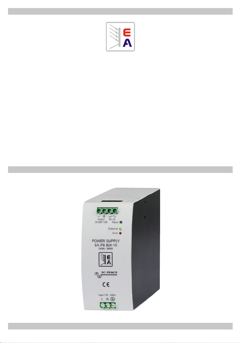
Übersicht / Overview
Allgemeines
Diese neu entwickelte Netzgeräteserie ist zur DIN-Schienenmontage vorgesehen und in den Leistungsklassen
von 80 bis 480W lieferbar. Alle Modelle sind mit einer
PFC (Power Factor Correction) ausgerüstet. Die Geräte
können einfach auf vormontierte DIN-Schienen (Typ 35)
aufgeschnappt werden. Sie sind in stabilen
gehäusen untergebracht und entsprechen der Schutzart IP
20.
Die Schaltnetzgeräte sind von höchster Qualität und
entsprechen Sicherheitsnormen wie EN 60950 (TÜV) und
UL 1012 sowie der EMV-Norm EN 55022. Weiterhin haben
sie einen weiten Eingangsspannungsbereich von 100V
bis 240VAC/+10% und können deshalb ohne Umschaltung
weltweit eingesetzt werden. Die Ausgangsspannung kann
über ein Potentiometer im angegebenen Bereich eingestellt
werden. Eine Parallelschaltung von Geräten ist möglich.
Stahlblech-
General
The newly developed power supply series is prepared for
DIN-Rail mounting and available in power classes of 80 up
to 480W. All models are equipped with a PFC (power factor
correction). They can easily be mounted on pre-installed
DIN rails (type 35). They are assembled in stable steel
cases and the protection class IP 20. By the use of the plug
terminals the maintenance and exchange is fast and easy.
The switched mode power supplies are of highest quality
and are according to the safety standards EN 60950 (TÜV)
and UL 1012 and the EMI standard EN 55022.
The mains input of the units is a wide range input of 100V
up to 240VAC/+10%. So this series can be used worldwide
without any switching. Parallel operation is possible.
Installation
Vor der ersten Inbetriebnahme des Gerätes sollten das Gehäuse und die Bedien- und Anzeigeelemente auf Beschädigungen hin untersucht werden. Wird eine Beschädigung
festgestellt, darf das Gerät nicht mit dem Netz verbunden
oder betrieben werden.
Das Gerät darf nicht geöffnet werden!
Eine Reparatur, Wartung oder Kalibrierung des Gerätes
darf nur durch Fachkräfte erfolgen.
Das Gerät darf nur an eine Netzleitung mit Schutzkontakt
angeschlossen werden. Die natürliche Luftzirkulation darf
an den Luftschlitzen nicht behindert werden. Abstände
von 40mm oben, 20mm unten und 10mm links und recht
werden mindestens empfohlen, wenn die Geräte unter
Dauerlast betrieben werden.
Der Anschluß der Eingangsspannung sowie der Last erfolgt
über Schraubklemmen, die Leitungen werden nach oben
bzw. unten herausgeführt. Achten Sie dabei auf richtige
Polung entsprechend der Bezeichnungen am Gerät!
Beschreibung
Die Geräte verfügen über einen potentialfreien Relaiskontakt, der den Zustand der Ausgangsspannung anzeigt
(Spannung vorhanden = Kontakt geschlossen, keine
Spannung = Kontakt offen) -> Öffnerprinzip. Die Geräte
sind kurzschluß- und überlastfest. Die Kühlung erfolgt
über Konvektion bei Temperaturen von 0...70°C. Ab 60°C
Umgebungstemperatur (ab 50% bei 480W-Modellen) ist
eine Leistungsbegrenzung von 2%/°C notwendig, die vom
Anwender zu berücksichtigen ist. Ein besonderes Merkmal
ist, daß die Geräte für 8 Sekunden 150% Leistung liefern
können, danach erfolgt Leistungsbegrenzung auf die
Nennleistung. Die Geräte benötigen bei wiederkehrender
150%iger Belastung eine Erholzeit, durch die sich ein Duty
Cycle (Puls-Pause-Verhältnis) von 10% ergibt.
Zum Beispiel darf das Gerät nach 8 Sekunden 150%iger
Last mindestens 72 Sekunden nur mit Nennlast oder
geringer belastet werden.
Installation
Before taking the unit into operation it is necessary to
inspect the housing, the controls, instruments and power
cable for signs of physical damage. If any physical damage
has been found, the equipment should not be connected
to the mains.
The unit may not be opened !
Any servicing, repair or calibration must only be carried out
by technically trained personnel.
The unit may only be operated at a line cord with ground
lead. The natural air circulation may not be impeded.
Distances of 40mm at the top, 20mm at the bottom and
10mm at the left and right are recommended
as minimum, if the unit is operated under constant load.
Only connect input voltage (mains) and load (output) by
using the included connectors. Always take care for correct
polarity!
Description
The units are equipped with an potential-free relay contact
output, which indicates the presence of the output voltage
(voltage present = contact closed, no voltage present =
contact open) -> breaker principle. The units are shortcircuit-proof and overtemperature and overload protected.
The cooling happens via convection at temperatures from
0...70°C. Above 60°C ambient temperature a derating of
2%/°C becomes necessary and has to be considered by
the user..
A special feature is the ability to provide 150% output
current for a time of maximum 8 seconds. After this the
unit needs to cool down for at least 9 times the time it was
overloaded, if this feature is used repeatedly. This results
in a duty cycle of 10%.
For example, if it was overloaded at 150% and 8 seconds,
it is required to load the unit with nominal power, or less,
for at least 72 seconds.
© EA Elektro-Automatik, DE-41747 Viersen, Helmholtzstr. 31-33, ☎ 02162-3785-0, Fax 02162-16230
2

Beschreibung / Description
Fehlermeldungen
Die LED „Error“ indiziert entweder Unterspannungs-,
Überspannungs- oder Übertemperaturfehler. Unterspannung tritt auf, wenn die Ausgangsspannung auf Grund zu
hoher Strombelastung auf unter ca. 20V (beim 24V-Gerät)
zusammenbricht. Bei einer Überspannung schaltet das
Gerät den Ausgang ab. Um das Gerät nach Beseitigung
der Fehlerursache wieder in Betrieb zu nehmen, muß die
Fehlermeldung zurückgesetzt werden. Dies geschieht, indem es so lange ausgeschaltet wird, bis die rote Error-LED
erlischt. Bei Übertemperatur wird der Ausgang abgeschaltet
und, nachdem sich das Gerät abgekühlt hat, automatisch
wieder eingeschaltet.
Error indication
The LED „Error“ indicates overvoltage, undervoltage and
overtemperature errors.
Undervoltage errors occur when the output voltage sinks
below approx. 20V (at a 24V model) because the current
limitation has become active. At an overvoltage protection
error the output is shut down. In order to operate the unit
again after the cause of the overvoltage is removed, it needs
to be reset. This is done by switching the unit off for at least
the time until the red LED needs to lapse. At overtemperature errors the output is shut down and, after the unit has
cooled down, automatically switched on again.
Technische Daten
Typ
Type
PS 812-07SM
PS 812-10SM
PS 812-16SM
PS 812-27SM
PS 824-04SM
PS 824-05SM
PS 824-10SM
PS 824-20SM
PS 848-02SM
PS 848-03SM
PS 848-05SM
PS 848-10SM
*) Nennstrom / Nominal current
100...240V
100...240V
100...240V
100...240V
100...240V
100...240V
100...240V
100...240V
100...240V
100...240V
100...240V
100...240V
AC Eing.
47-63Hz
AC Input
47-63Hz
Fehlermeldung
Error indication
DC Eings.spannung
DC input
voltage
150...370V
150...370V
150...370V
150...370V
150...370V
150...370V
150...370V
150...370V
150...370V
150...370V
150...370V
150...370V
Ausgang
Output
Leistgs.-
faktor
Power
factor
>0.98
>0.98
>0.98
>0.98
>0.98
>0.98
>0.98
>0.98
>0.98
>0.98
>0.98
>0.98
DC Ausg.-
bereich
DC output
range
12...15V
12...15V
12...15V
12...15V
24...28V
24...28V
24...28V
24...28V
48...56V
48...56V
48...56V
48...56V
Technical specications
OVP
Welligk.
Bereich
mV
pp
OVP
Ripple
range
mV
pp
16V+1V
DC
16V+1V
DC
16V+1V
DC
16V+1V
DC
30V+1V
DC
30V+1V
DC
30V+1V
DC
30V+1V
DC
58V+1V
DC
58V+1V
DC
58V+1V
DC
58V+1V
DC
<40
<50
<50
<80
<40
<50
<50
<120
<40
<50
<100
<180
Ausg.-
Nennlei-
strom*
stung
Output
Output
power
current*
6.6A
80W
10A
120W
16A
240W
26.5A
480W
3.3A
80W
5A
120W
10A
240W
20A
480W
1.6A
80W
2.5A
120W
5A
240W
10A
480W
Spannungseinstellung
Voltage adjust
Gewicht
Weight
0.9kg
0.9kg
1kg
1,3kg
0.9kg
0.9kg
1kg
1,3kg
0.9kg
0.9kg
1kg
1,3kg
Abmessungen
BxHxT (mm)
Dimensions
WxHxD (mm)
48x126x112
48x126x112
60x126x112
78x126x125
48x126x112
48x126x112
60x126x112
78x126x125
48x126x112
48x126x112
60x126x112
78x126x125
Netzeingang
Mains input
© EA Elektro-Automatik, DE-41747 Viersen, Helmholtzstr. 31-33, ☎ 02162-3785-0, Fax 02162-16230
3

EA-Elektro-Automatik GmbH & Co. KG
Entwicklung - Produktion - Vertrieb
Helmholtzstraße 31-33
41747 Viersen
Telefon: 02162 / 37 85-0
Telefax: 02162 / 16 230
ea1974@elektroautomatik.de
www.elektroautomatik.de
 Loading...