

Labornetzgerät
Laboratory Power Supply
Alimentation de Laboratoire
EA-PS 3032-20 B
0...32V / 0...20A
Art.-Nr.: 35320177


Wichtige HinweiseTechnische Daten
Netz
Spannung 88...264V
Frequenz 50 / 60Hz
Leistungsfaktorkorrektur (PFC) >0,99
Sicherung 10A T
Ausgang
Spannung
- Einstellbereich 0...32V
- Feineinstellbereich ca. 1,6V
- Stabilität 10...100% Last <20mV
- Stabilität
- Restwelligkeit <10mV
+
10% U
E
<2mV
rms
- Ausregelzeit 10...90% Last <3ms
- Ausregelzeit 90...10% Last <3ms
Strom
- Einstellbereich 0...20A
- Feineinstellbereich ca. 1,0A
- Stabilität 10...100% U
A
- Restwelligkeit <5mA
<50mA
rms
Schutzfunktionen
- Überspannungsschutz (OVP) 0...35,2V
- Überstromschutz (CC) 0...20A
- Übertemperaturschutz (OT) Abschaltung
Bedienelemente
Spannungseinstellung Potentiometer grob / fein
Stromeinstellung Potentiometer grob / fein
Überspannungsschutz Trimmpoti 10-gang
Voreinstellung OVP / Strom Taster (Preset)
Anzeigeelemente
Spannung LED 7-Segment 3stellig
Strom LED 7-Segment 3stellig
Überspannungsschutz LED 7-Segment 3stellig
Zustandsanzeigen LEDs
Schnittstelle analog
Eingänge Signal
Spannung 0...100% 0...10V
Strom 0...100% 0...10V
Schnittstelle Ein/Aus (SEL-enable) offener Kollektor
Ausgang Ein/Aus (Standby) offener Kollektor
Ausgänge Signal
Spannung 0...100% 0...10V
Strom 0...100% 0...10V
Versorgungsspannung (+VCC) 12...15V 100mA
Referenzspannung (VREF) 10,0V 5mA
Überspannungsanzeige (OVP) offener Kollektor
Übertemperaturanzeige (OT) offener Kollektor
Regelungsart (CV/CC) offener Kollektor
Verschiedenes
Betriebstemperatur 0...40°C
Lagertemperatur -20...70°C
Luftfeuchtigkeit rel. <80% ohne Kondensation
Abmessungen (BxHxT) 240x120x285mm
Einbaumaße 240x132x325mm
Zubehör
USB-Schnittstelle UTA12
Auspacken
Prüfen Sie nach dem Auspacken den Inhalt auf Vollständigkeit
und das Gerät auf mechanische Beschädigungen und lose Teile
im Inneren. Falls ein Transportschaden vorliegt ist sofort der
Lieferant zu informieren. Das Gerät sollte dann nicht in Betrieb
genommen werden.
Inbetriebnahme
Das Gerät ist aus Si cherh eitsg ründen nur an eine r
Schutzkontaktsteckdose oder einem Schutz-Trenntransformator
der Schutzklasse 2 zu betreiben. Die Lüftungsöffnungen an
den Seiten des Gerätes und der Luftaustritt an der Rückseite
dürfen nicht abgedeckt werden.
Netzspannungswahl und Sicherungswechsel
Vor Inbetriebnahme des Gerätes ist zu prüfen ob die verfügbare
Netzspannung dem Wert auf dem Netz-spannungswahlschalter
entspricht. Bei Änderung der Netzspannung ist der Wechsel
der Netzsicherungen notwendig. Die Sicherungen dürfen nur
gewechselt werden wenn das Gerät vom Netz getrennt ist. Die
entsprechenden Angaben hierzu und die Elemente benden
sich auf der Rückseite des Gerätes.
Allgemeines
Die Geräte der Serie PS3000B (600W bis 650W Ausgangsleistung) sind getaktete Netzteile mit einer sinusförmigen
Netzstromaufnahme (PFC). Neben einem kompakten Aufbau,
geringem Gewicht und guten elektrischen Werten besitzen
die Geräte eine Vielzahl von Ausstattungsmerkmalen. Hierzu
gehören Grob- und Feineinstellung von Spannung und Strom,
eine Preset-Funktion zur Voreinstellung von Strom und OVP
und diverse Zustandsanzeigen. Die Kühlung erfolgt über einen
temperaturgeregelten Lüfter. Weiterhin verfügen die Geräte
über eine Analogschnittstelle. Diese kann mit dem externen
Interface EA-UTA12 zur USB-Schnittstelle erweitert werden.
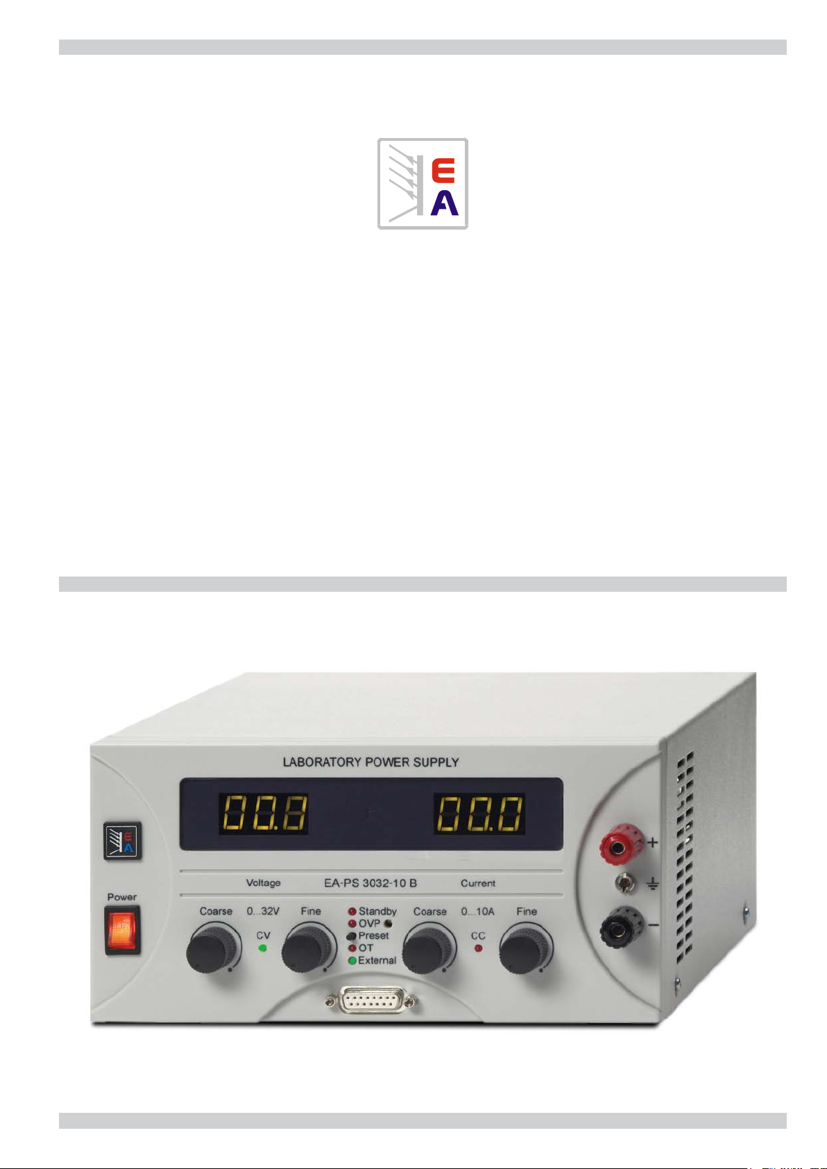
Bedien- und Anzeigeelemente
Die Ausgangsspannung und der Ausgangsstrom der Geräte
können entweder über je einen Grob- und Feinregler eingestellt
oder über die analoge Schnittstelle mit 0...10V geregelt werden.
Die entsprechenden Werte können an einer 3stelligen LED 7Segment-Anzeige oder über die Monitorausgänge der analogen
Schnittstelle (0...10V) abgelesen werden.
Während der Betätigung des Preset-Tasters können an den
LED-Anzeigen der eingestellte Strom, sowie der über einen 10Gang-Trimmer auf der Front eingestellte Überspannungsschutz
(OVP) abgelesen und präzise eingestellt werden.
Die Betriebsart, in der das Gerät im Moment arbeitet, wird über
zwei LEDs angezeigt. Hier steht CV für Spannungsregelung
und CC für Stromregelung.
Weitere LEDs zeigen den Zustand des Gerätes an.
LED External = Analogschnittstelle aktiv
LED OT = Abschaltung durch Übertemperatur
LED OVP = Abschaltung durch Überspannung
LED Standby = Abschaltung durch Analogschnittstelle
Ausgangsklemmen
Der Ausgang steht sowohl an zwei Sicherheitsbuchsen auf
der Front als auch an einer Schraubklemme auf der Rückseite
zur Verfügung. Hier benden sich auch die Anschlüsse für
eine Fernfühlung (Sense) mit der Spannungsabfälle auf den
Lastleitungen kompensiert werden können.
35320177_MA_03, 11/2010
© EA Elektro-Automatik GmbH & Co. KG, DE-41747 Viersen, Helmholtzstr. 31-33, Tel. 02162-3785-0, Fax. 02162-16230
3
Technische Beschreibung
Allgemeines
Die Labornetzgeräte der Serie PS3000B sind für einen universellen Einsatz in Entwicklung, Forschung, Ausbildung, Service und
Produktion entwickelt wurden. Die übersichtliche Anordnung, eine einfache und intuitive Bedienung und bewährte Technik zeichnen
diese Geräte aus.
Einstellungen des Ausgangs
Die Ausgangsspannung und der Ausgangsstrom können stufenlos von null bis zum Nennwert eingestellt werden wobei das Gerät
dann entweder im Spannungsregel- (CV) oder im Stromregelmodus (CC) arbeitet.
Lastanschluß
Die Last kann an den auf der Frontseite bendlichen Sicherheitsklemmen oder an den Schraubklemmen auf der Rückseite
angeschlossen werden.
Fernfühlung
Soll die Spannung direkt an der Last ausgeregelt werden um den Spannungsabfall auf den Lastleitungen zu berücksichtigen, so
sind die Fühlerleitungen auf der Rückseite (+ und - Sense) mit an der Last anzuschließen. Achtung! Die vorhandenen Brücken
zwischen +Sense und +Ausgang sowie -Sense und -Ausgang sind in diesem Fall zu entfernen.
Überspannungsschutz (OVP)
Die Geräte sind mit einem Überspannungsschutz ausgerüstet der auf der Gerätefront mittels Schraubendreher von ca. 0V bis
10% über Nennspannung eingestellt werden kann. Sollte also durch einen Bedienfehler oder Defekt die Ausgangsspannung über
den eingestellten Wert steigen so wird der Ausgang abgeschaltet. Dies wird dann über die LED OVP (Over voltage protection)
angezeigt.
Lüftersteuerung und Übertemperaturschutz (OT)
Das Gerät ist mit einem temperaturabhängig geregeltem Lüfter ausgestattet. Der Lufteintritt an den Seiten und der Luftaustritt an
der Rückseite des Gerätes darf nicht versperrt werden. Sollte die Temperatur im Inneren des Gerätes am Transformator oder der
Leistungsendstufe zu hoch werden so wird der Ausgang zum Schutz des Gerätes abgeschaltet. Dies wird dann über die LED OT
(Over temperature) angezeigt.
Schnittstelle
Die serienmäßig vorhandene, analoge Schnittstelle ermöglicht es dem Anwender das Gerät mit analogen Signalen zu steuern
und zu überwachen. Das optional erhältliche Interface UTA12 kann die Geräte direkt vom PC aus mittels USB-Anschluß komplett
steuern. Die benötigte Software bzw. Kabel sind im Lieferumfang des UTA12 enthalten.
Pin-Belegung Analogschnittstelle
Pin Name I/O Beschreibung Phasenlage Beschreibung, Pegel, Impedanz
1 VSEL I Sollwert Spannung - 0...10V, Eingangsimpedanz >40k
2 CSEL I Sollwert Strom - 0...10V, Eingangsimpedanz >40k
3 VREF O Referenzspannung - 10V, I
max
5mA
4 DGND - Ground - Ground für Steuer- und Meldesignale
5 SEL-enable I Umschaltung Local/Extern Low=Extern Open=Lokal U
6 OT O Übertemperatur Low=OK Open=Fehler U
max
max
20V, I
20V, I
2mA, U
max
-25mA, offener Kollektor
max
low
<1V
7 NC - - - 8 NC - - - 9 VMON O Istwert Spannung - 0...10V, I
10 CMON O Istwert Strom - 0...10V, I
max
max
2mA
2mA
11 AGND - Ground - Ground für Sollwerte, Istwerte & VREF
12 +VCC O Versorgungsspannung - 11...15V, I
13 Standby I Ausgang Ein/Aus Low=Aus Open=Ein U
14 OVP O Überspannung Low=OK Open=Error U
15 CV/CC O Spannungs/Stromregelung Low=CV Open=CC U
max
max
max
20V, I
20V, I
20V, I
100mA
max
2mA, U
max
-25mA, offener Kollektor
max
-25mA, offener Kollektor
max
low
<1V
Die Massen des Gerätes (AGND und DGND) ist elektrisch leitend mit dem Minus-Ausgang
verbunden!
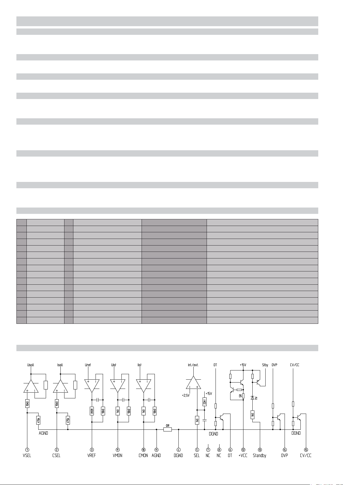
Interne, vereinfachte Darstellung der Beschaltung der analogen Schnittstelle
© EA Elektro-Automatik GmbH & Co. KG, DE-41747 Viersen, Helmholtzstr. 31-33, Tel. 02162-3785-0, Fax. 02162-16230
4
Technische Beschreibung
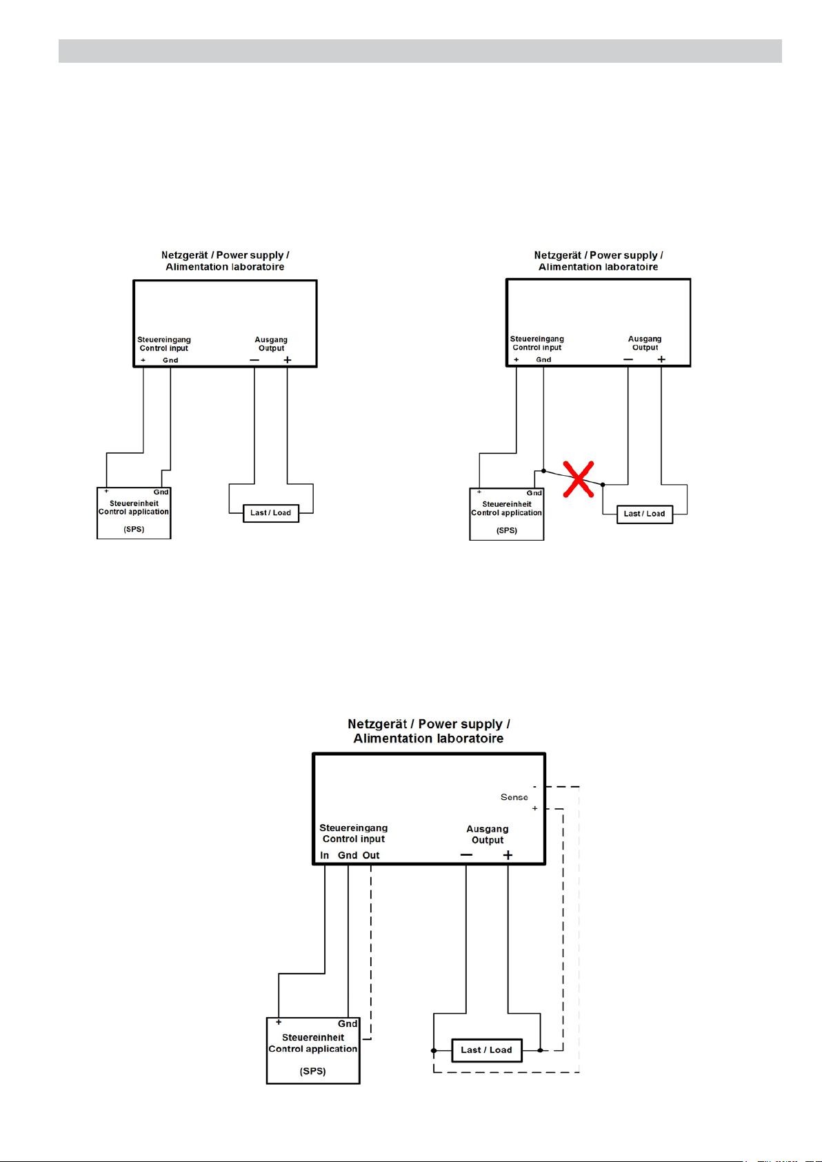
Achtung! Die Signalmasse (GND) an der analogen Schnittstelle und der Minus (-) Ausgang sind intern
miteinander verbunden. Bei getrennter Verlegung dieser beiden Leitungen zu einer externen Steuereinheit
(z.B. SPS) und einer Last dürfen diese dort nicht direkt verbunden werden, da sonst eine Aufteilung des
Laststromes über die meist dünne Steuersignalmasse GND auftreten kann!
Das Problem tritt nicht auf, wenn an einer Stelle eine galvanische Trennung der Steuersignale zum Ausgang
realisiert wird, wie z.B. bei Verwendung eines CAN- oder IEEE-Interfaces.
Richtig Falsch
Eine mögliche Lösung ist unten zusehen. Um die Spannung an der Last zu messen, wird „Remote sense“ verdrahtet.
Der Meßausgang UMON kann mit der Steuerapplikation erfaßt und gemessen werden.
© EA Elektro-Automatik GmbH & Co. KG, DE-41747 Viersen, Helmholtzstr. 31-33, Tel. 02162-3785-0, Fax. 02162-16230
5

Important DetailsTechnical specifications
Input
Voltage 88...264V
Frequency 50 / 60Hz
Fuse >0.99
T10A
Output
Voltage
- Fine adjustment range 0...32V
- Adjustment range approx. 1.6V
- Stability 0...100% Load <20mV
- Stability
- Ripple <10mV
+
10% U
IN
<2mV
rms
- Regulation 10...90% Load <3ms
- Regulation 90...10% Load <3ms
Current
- Adjustment range 0...20A
- Fine adjustment range approx. 1A
- Stability 0...100% U
OUT
- Ripple <5mA
<50mA
rms
Protection
- Overvoltage protection (OVP) 0...35.2V
- Overcurrent protection (CC) 0...20A
- Overtemperature protection (OT) Output shutdown
Control elements
Voltage adjustment Potentiometers coarse/ne
Current adjustment Potentiometers coarse/ne
Overvoltage protection Trimmer 10 turns
Preset OVP / Current Pushbutton (Preset)
Indicators
Voltage LED 7 segment, 3 digits
Current LED 7 segment, 3 digits
Overvoltage protection LED 7 segment, 3 digits
Status indication by LEDs
Analogue interface
Inputs Signal
Voltage 0...100% 0...10V
Current 0...100% 0...10V
Remote Control On/Off (SEL- open collector
Output On/Off (Standby) open collector
Outputs Signal
Voltage 0...100% 0...10V
Current 0...100% 0...10V
Supply voltage (+VCC) 12...15V 100mA
Reference voltage (VREF) 10.0V 5mA
Overvoltage indicator (OVP) open collector
Overtemperature indicator (OT) open collector
Control mode (CV/CC) open collector
Miscellaneous
Operating temperature 0...40°C
Storage temperature -20...70°C
Relative humidity <80% w/o condensation
Dimensions (WxHxD) 240x120x285mm
Installation dimensions (WxHxD) 240x132x325mm
Accessories
USB interface UTA12
Unpacking
Check the contents after unpacking for missing parts or
accessories and the unit for any apparent mechanical damages
and loose parts inside the unit. In case of a transport damage
please inform the seller immediately. In that case do not take
the unit into operation.
Commissioning
For safety reasons the unit may only be operated at a mains
power connection provided with a safety ground or via an
insulating transformer safety class 2. The air in- and outlets
on the back side may never be obstructed in order to ensure
proper cooling.
Mains power voltage selection and fuse replacement
Before putting the unit into operation make sure that the
available mains power voltage and the setting of the input
voltage selector on the back have the same value (115 or
230 V). If it is required to adjust the input selector to the mains
power voltage value, an input fuse with an appropriate voltage
value has to be t as well. The fuse may only be changed or
replaced whilst the unit is disconnected from the mains power
line. The fuse and the respective values are shown on the back
side of the unit.
General
The power supply series EA-PS 3000B (600 – 650 W output
power) is of primary switching technology and is provided with
a Power Factor Correction circuit (i.e. PFC, sinusoidal input
current). This series is distinguished by its compact built-up,
lightweight, excellent electrical values and extended operational
features, such as ne and coarse adjust of output voltage and
current, preset function for output voltage and overvoltage
protection (OVP) and the display of various operation
statuses. Cooling is provided via a temperature controlled fan.
Furthermore, this series features an analogue interface (0-10V)
for remote control and can, in addition, be tted with an external
USB interface adapter (EA-UTA12).
Controls and displays
Output voltage and current can be preset through coarse and
ne potentiometers placed on the front panel or via 0…10V
through the analogue interface. The respective values are
shown on the 3-digit 7-segment LED meters or via the analogue
interface (0…10V).
Whilst pushing the preset button, the preset current and the
preset overvoltage protection value (i.e. OVP, setting through
the 10-turn potentiometer on the front), are displayed on the
LED meters.
The regu latio n m ode is ind i cate d v ia two LEDs .
LED CV = constant voltage mode
LED CC = constant current mode
Furthermore, the LEDs on the front panel show the following
operation conditions.
LED Standby = Shut down by analogue interface
LED OVP = Shut down by overvoltage (OVP)
LED OT = Shut down by overheating (OT)
LED External = Analogue interface active
Output terminals
The output is provided through two safety sockets on the front
panel and in addition via screw terminals on the rear side. The
connections for “remote sensing” .i.e. to compensate the voltage
loss on the load wires, are placed on the rear side as well.
© EA Elektro-Automatik GmbH & Co. KG, DE-41747 Viersen, Helmholtzstr. 31-33, Tel. 02162-3785-0, Fax. 02162-16230
6

Technical description
General
The laboratory power supply series PS3000B is an ideal equipment for the use in R&D , schools (vocational training), maintenance
and production. The attractive design, the easy and intuitive handling and the rugged and reliable technology make this series an
ideal tool for technicians, engineers and their apprentices.
Adjustment of the output
Output voltage and output current can be set from 0 up to the max. value. Both operation modes, constant voltage (CV) or constant
current (CV), are selected automatically (auto crossover).
Load connection
The load can be connected through the safety sockets on the front or via screw terminals on the rear side.
Remote sense
The output voltage loss resulting from long DC output cables can be compensated by connecting the sense terminal (+ and – sense)
on the rear side with the + and – input terminals of the load. For this purpose please remove the jumpers from the terminals +
Sense and – Sense rstly.
Overvoltage protection (OVP)
The units are equipped with an overvoltage protection (OVP). The value can be adjusted with a screw driver between 0V...110% of
the rated output voltage. If the output voltage becomes higher than the preset value, due to a user’s mistake or an internal defect,
the output will shut down and the LED OVP will light up.
Fan control and overtemperature protection (OT)
The series is equipped with a temperature regulated fan speed. In case the temperature of the transformer or the power stage
becomes too high, the output is switched off automatically. The LED OT (overtemperature) will light up. After cooling down the unit
will reset automatically.
Interfacing
The built-in analogue interface allows to control the unit externally through analogue signals (0-10 V)
With the external, optional interface UTA12 it is possible to control the unit via a personal computer. The software for this application
(UTA12) is provided.
Pin assignment analogue interface
Pin
Name
1
VSEL
2
CSEL
3
VREF
4
DGND
5
SEL-enable
6
OT
7
NC
8
NC
9
VMON
10
CMON
11
AGND
12
+VCC
13
Standby
14
OVP
15
CV/CC
I/O
Description
I
Nominal value voltage
I
Nominal value current
O
Reference value
-
Ground
I
Select local / extern
O
Overtemperature
-
-
-
-
O
Actual value voltage
O
Actual value current
-
Ground
O
Supply voltage
I
Output on / off
O
Overvoltage
O
Voltage or current control
Phasing
Low=Extern
Low=OK
Low=Off
Low=OK
Low=CV
Open=Local
Open=Error
Open=On
Open=Error
Open=CC
Description, level, impedance
0…10V, input impedance >40k
0…10V, input impedance >40k
10V Imax.5mA
Ground for control and status signal
Umax. 20V, Imax.2mA, U low <1V
Umax. 20V, Imax.-25mA, Open Collector
-
-
0...10V, Imax.2mA
0...10V, Imax.2mA
Ground nominal and actual value, VREF
11...15V, Imax.100mA
Umax. 20V, Imax.2mA, U low <1V
Umax. 20V, Imax.-25mA, Open Collector
Umax. 20V, Imax.-25mA, Open Collector
The grounds of the unit (AGND and DGND) are electrically connected to minus output!
Internal schematic diagram analogue interface
© EA Elektro-Automatik GmbH & Co. KG, DE-41747 Viersen, Helmholtzstr. 31-33, Tel. 02162-3785-0, Fax. 02162-16230
7

Technical description
Important! The signal ground (GND) of the analogue interface and the negative (-) output are internally
connected. When wiring these two lines seperately to a control application (eg. a SPS) and a load, they must
not be connected directly to each other at the external application! Else the load current may be distributed
over both lines and damage the normally small-sized control lines.
This problem does not occur if a galvanic isolation of the control signals is used at any point, for instance
when using a CAN or GPIB interface card.
Correct Wrong
One possible solution is given below. In order to measure the voltage at the load, wire the „Remote sense“ feature.
The actual value output UMON can be wired with the control application to measure the voltage.
© EA Elektro-Automatik GmbH & Co. KG, DE-41747 Viersen, Helmholtzstr. 31-33, Tel. 02162-3785-0, Fax. 02162-16230
8

Données technique Détails importants
Entrée
Tension 88...264V
Fréquence 50 / 60Hz
Fusible >0.99
T10A
Sortie
Tension
- Plage de réglage 0...32V
- Plage de réglage précision approx. 1,6V
- Stabilité 0...100% charge <20mV
- Stabilité +10% U
E
- Ondulation résiduelle <10mV
<2mV
rms
- Temps de comp. 10...90% charge <3ms
- Temps de comp. 90...10% charge <3ms
Courant
- Plage de réglage 0...20A
- Plage de réglage précision approx. 1A
- Stabilité 0...100% U
S
- Ondulation résiduelle <5mA
<50mA
rms
Protection
- Protection c. la surtension (OVP) 0...35,2V
- Détection de surintensité (CC) 0...20A
- Élévation de température (OT) Arrêt de la sortie
Éléments de réglage
Tension Potentiomètre gros/n
Courant Potentiomètre gros/n
Protection c. la surtension Trimmer 10 rot.
Préréglage Parafoudre/Courant Bouton-poussoir
Èlèments de afchage
Tension DEL 7 seg. 3-chiffres
Courant DEL 7 seg. 3-chiffres
OVP DEL 7 seg. 3-chiffres
Afchages d´état DEL
Interface analogique
Entrée Signal
Tension 0...100% 0...10V
Courant 0...100% 0...10V
Command à distance marche/arrét collecteur ouvert
Sortie marche/arrét (Standby) collecteur ouvert
Sortie Signal
Tension 0...100% 0...10V
Courant 0...100% 0...10V
Alimentation (+VCC) 12...15V 100mA
Référence tension (VREF) 10,0V 5mA
Indication OVP collecteur ouvert
Indication OT collecteur ouvert
Indication mode CV/CC collecteur ouvert
Diverses
Température de fonctionnement 0...40°C
Température de stockage -20...70°C
Humidité atmosphérique <80% sans condensation
Dimensions (LxHxP) 240x120x285mm
Installation dimensions (LxHxP) 240x132x325mm
Accessories
Interface USB UTA12
Déballage
Avant de relier l’appareil au secteur, une inspection visuelle
doit être faite pour s’assurer que l’alimentation n’a pas subi
de dommages pendant le transport. Si l’appareil montre un
dommage extérieur en informer votre fournisseur. En aucun
cas, il ne faut l’utiliser.
Conditions de fonctionnement
Pour des raisons de sécurité, l’appareil doit être branché
impérativement sur une prise secteur munie de la terre. Les
entrées et sorties d’air situées à l’arrière ne doivent pas être
obstruées an d’assurer un refroidissement correct.
Sélection de la tension secteur et remplacement du fusible
Avant de brancher l’appareil sur le secteur, s’assurer que le
sélecteur de tension d’entrée est positionné sur la valeur de la
tension secteur disponible (110V ou 230V).
Si la tension secteur fournie est différente du réglage, le
fusible d’entrée devra être changé, le remplacement ne peut
être effectué que lorsque l’appareil est débranché de la prise
secteur. Les valeurs de fusible sont montrées en face arrière.
Caractéristiques générales
La série des alimentations PS3000B 600 - 650 watts est du
type régulation série. Ces modèles procurent pour une sortie
à tension constante et courant constant à faible ondulation
résiduelle, une régulation rapide et plusieurs autres possibilités.
Le refroidissement est obtenu par des ventilateurs asservis en
température. Tous les modèles sont équipés d’une interface
analogique pour une commande externe en 0-10V ou par une
interface USB (option EA-UTA 12).
Commandes et afchages
La tension et le courant de sortie peuvent être préréglés à
l’aide de potentiomètres réglage approché et réglage n situés
en face avant ou à l’aide de l’interface analogique 0…10V
en face avant. Les valeurs de sortie sont afchées sur les
afchages digitaux 2000 points 7 segments ou via l’interface
0-10V analogique.
Pendant le bouton-poussoir «preset» est enfoncé la valeur de
préréglage du courant et la valeur de préréglage de la surtension
de protection (i.e. OVP réglage par le potentiomètre 10 tours en
face avant) sont afchées sur les indicateurs LED.
Le mode de régulation est indiqué via deux LED.
LED CV = c’est-à-dire mode tension constant
LED CC = c’est-à-dire mode courant constant
Les conditions de fonctionnement sont indiquées aussi par LED:
LED External = Interface analogique active
LED OT = Arrêt par surchauffe (OT)
LED OVP = Arrêt par surtension (OVP)
LED Standby = Arrêt par l’interface analogique
Sorties
La tension de sortie est délivrée aux bornes de sécurité en face
avant et via des sorties sur vis à l’arrière. Les branchements
de compensation (pour compenser la chute de tension dans
les ls) sont placés en face arrière.
© EA Elektro-Automatik GmbH & Co. KG, DE-41747 Viersen, Helmholtzstr. 31-33, Tel. 02162-3785-0, Fax. 02162-16230
9

Description technique
Général
La série d’alimentations PS3000B est un équipement adapté aux applications en R&D, enseignement, maintenance et production.
D’une présentation et d’une conception intuitive font de ce produit un outil apprécié par les ingénieurs et techniciens.
Réglage de la sortie
La tension et le courant de sortie peuvent être réglés de 0 à la valeur maximum, les deux modes de fonctionnement, tension
constante „CV“ ou courant constant „CC“ sont sélectionnés automatiquement (cross over automatique).
Branchement de la charge
La charge peut être branchée aux bornes de sécurité en face avant ou sur les vis à l’arrière.
Compensation
La perte de tension dans les câbles peut être compensée en reliant les bornes „sense“ + et – à l’arrière de l’appareil aux bornes +
et – de la charge. Dans ce cas, enlever les pontages aux bornes „sense +“ et „sense –“.
Protection de surtension (OVP)
La valeur de la protection en surtension peut être réglée au tournevis entre 0 et jusqu’à +10% de la valeur de sortie disponible. Si
la tension de sortie devient supérieure à la valeur préréglée, soit par erreur de manipulation soit par défaut interne, elle se coupera
et la LED „OVP“ s’éclairera.
Commande ventilateur et protection de surchauffe (OT)
Cette série est équipée d’une régulation température de la vitesse du ventilateur. Si la température du transformateur ou de l’étage
de sortie devient trop élevée la sortie est automatiquement coupée. La LED „OT“ (over temperature) s’éclaire. Après refroidissement,
l’appareil se réarme automatiquement.
Interface
L’alimentation laboratoire et muni d’un interface standard analogiquelle permet le control et la recopie sur des seniaux analogiques
par 0 - 10 V. Avec l’Interface (option) UTA 12 elle peut etre connectée et controlée directement par ordinateur sur le port USB. Le
logiciel et le cable de connexion sont furnis avec l’option UTA 12.
Connecteur d’interface analogue
Pin
Nom
1
VSEL
2
CSEL
3
VREF
4
DGND
5
SEL-enable
6
OT
7
NC
8
NC
9
VMON
10
CMON
11
AGND
12
+VCC
13
Standby
14
OVP
15
CV/CC
I/O
Description
I
Valeur de consigne de voltage
I
Valeur de consigne de courant
O
Tension de révérence
-
Masse
I
Inversion Local / Extern
O
Élévation de température
-
-
-
-
O
Valeur de réelle de voltage
O
Valeur de réelle de courant
-
Masse
O
Tension d’alimentation
I
Sortie marche / arrét
O
Surtension
O
Tension/Courant constante
Position de phase
Low=Extern
Low=OK
Low=Arrêt
Low=OK
Low=CV
Open=Local
Open=Error
Open=Marche
Open=Erreur
Open=CC
Description, Niveau, Impédance
0…10V, impédance de entrée >40k
0…10V, impédance de entrée >40k
10V Imax. 5mA
Masse pour signal de commande et alarm
Umax. 20V, Imax.2mA, U low <1V
Umax. 20V, Imax.-25mA, Open Collector
-
-
0...10V, Imax.2mA
0...10V, Imax.2mA
Masse pour valeur de consigne et réelle, VREF
11...15V, Imax.100mA
Umax. 20V, Imax.2mA, U low <1V
Umax. 20V, Imax.-25mA, Open Collector
Umax. 20V, Imax.-25mA, Open Collector
Les masses (AGND et DGND) du interface analogue est referée a la sortie negative!
Interne schéma des circuits d´ interface analogique
© EA Elektro-Automatik GmbH & Co. KG, DE-41747 Viersen, Helmholtzstr. 31-33, Tel. 02162-3785-0, Fax. 02162-16230
10

Indication d‘emploi importante
Attention! La masse du signal (GND) de l’interface analogique et la sortie négative (-) sont reliées
entre elles de manière interne. Si ces deux conducteurs dont le câblage a été effectué séparément
sont connectés à une unité de commande externe (automate programmable PLC, p. ex.) et à un
consommateur de courant, il faut absolument que ces conducteurs ne soient pas directement reliés
à cet endroit car il peut se produire une répartition du courant par l’intermédiaire de la masse du
signal de commande GND qui en règle générale est une connexion très mince !
Le problème n’apparaît pas si un isolement galvanique des signaux de commande est réalisé vers
la sortie, p. ex. en utilisant une interface CAN ou IEEE ou encore un amplicateur de signaux.
Correcte
Une des solutions à ce problème est illustrée ci-dessous. Pour mesurer la tension au niveau du consommateur
connecté, le dispositif de compensation de chute de tension « Remote Sense » est câblé.
Erronée
© EA Elektro-Automatik GmbH & Co. KG, DE-41747 Viersen, Helmholtzstr. 31-33, Tel. 02162-3785-0, Fax. 02162-16230
11

Bezeichnung der Bedienelemente
Operating controls
Désignation des éléments de commande
3 1286
1
Netzschalter
2
Drehregler Spannung grob
3
Anzeige Spannung (Preset=OVP)
4
Regelungsart Spannungsregelung
5
Drehregler Spannung fein
6
Taster Voreinstellung OVP / Strom
7
Zustandsanzeigen
8
Analogschnittstelle
9
Einstellung Überspannungsschutz
10
Drehregler Strom grob
11
Regelungsart Stromregelung
12
Anzeige Strom
13
Drehregler Strom fein
14
Erdungsbuchse
15
Ausgangsklemmen
7 9 10 132 51 154 11
Mains switch
Voltage rotary control (coarse)
Display voltage (Preset=OVP)
Voltage control mode indication
Voltage rotary control (ne)
Pushbutton Preset OVP/current
Status indication
Analogue interface
Adjustment overvoltage protection
Current rotary control (coarse)
Current control mode
Display current
Current rotary control (ne)
Grounding connector
Output terminals
14
Interrupteur du réseau
Bouton de réglare de tension grossier
Indicateur de la tension
Réglage de tension
Bouton de réglare de tension n
Bouton poussoir préréglage OVP / courant
Visualisation d´état
Interface analogique
Ajustage Protection contre les surtension
Bouton de réglare de courant grossier
Réglage de courant
Indicateur de la courant
Bouton de réglare de courant n
Borne de terre
Point de sortie
© EA Elektro-Automatik GmbH & Co. KG, DE-41747 Viersen, Helmholtzstr. 31-33, Tel. 02162-3785-0, Fax. 02162-16230
12
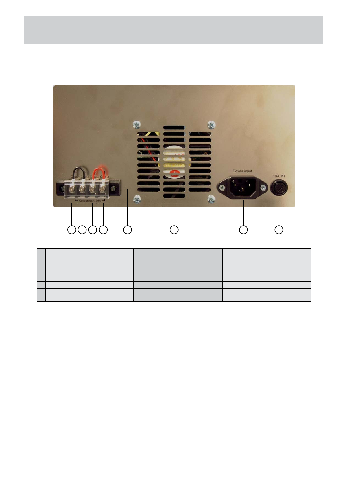
Bezeichnung der Bedienelemente
Operating controls
Désignation des éléments de commande
1
- Ausgang
2
- Fernfühlung
3
+ Fernfühlung
4
+ Ausgang
5
Ausgangsklemmen Rückseite
6
Luftaustritt
8
Kaltgeräteeinbaustecker
9
Netzsicherung
5 7 864321
- Output
- Sense
+ Sense
+ Output
Output terminals rearside
Air outlet
Power receptacle
Line fuse
- Sortie
- Détecteur
+ Détecteur
+ Sortie
Barre á bornes du revers
Bouche d´aération
Branchement au secteur
Fusible d´entrée
© EA Elektro-Automatik GmbH & Co. KG, DE-41747 Viersen, Helmholtzstr. 31-33, Tel. 02162-3785-0, Fax. 02162-16230
13


EA-Elektro-Automatik GmbH & Co. KG
Entwicklung - Produktion - Vertrieb
Development - Production - Sales
Helmholtzstraße 31-33
41747 Viersen
Germany
Telefon: 02162 / 37 85-0
Telefax: 02162 / 16 230
ea1974@elektroautomatik.de
www.elektroautomatik.de
 Loading...