

EA Elektro Automatik EA-PS 2016-050, EA-PS 2016-100, EA-PS 2032-025, EA-PS 2032-050 Instruction Manual [ml]
Labornetzgerät
Laboratory
P o wer Supply
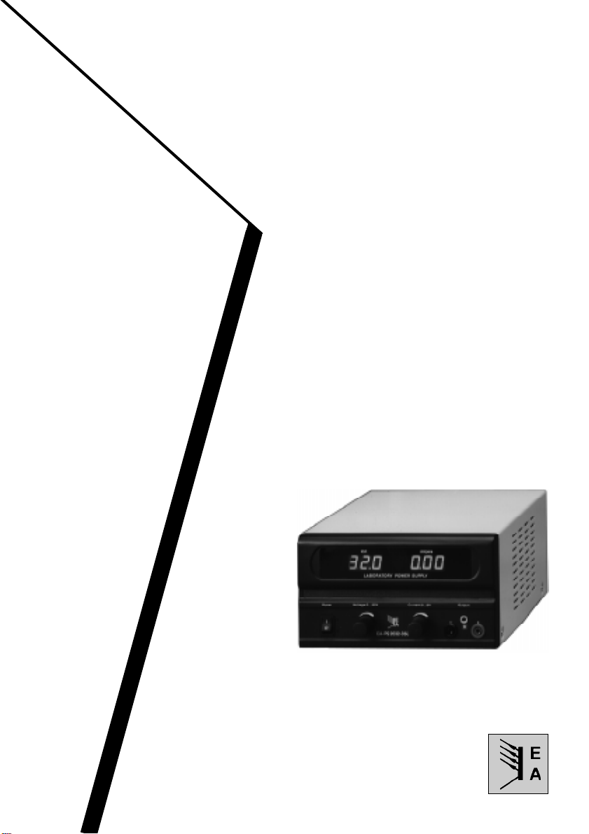
EA-PS 2016-050 0...16V/0...5A
Art.-Nr.: 39 200 100
EA-PS 2016-100 0...16V/0...10A
Art.-Nr.: 39 200 101
EA-PS 2032-025 0...32V/0...3A
Art.-Nr.: 39 200 102
EA-PS 2032-050 0...32V/0...5A
Art.-Nr.: 39 200 103
EA - ELEKTRO-AUTOMATIK
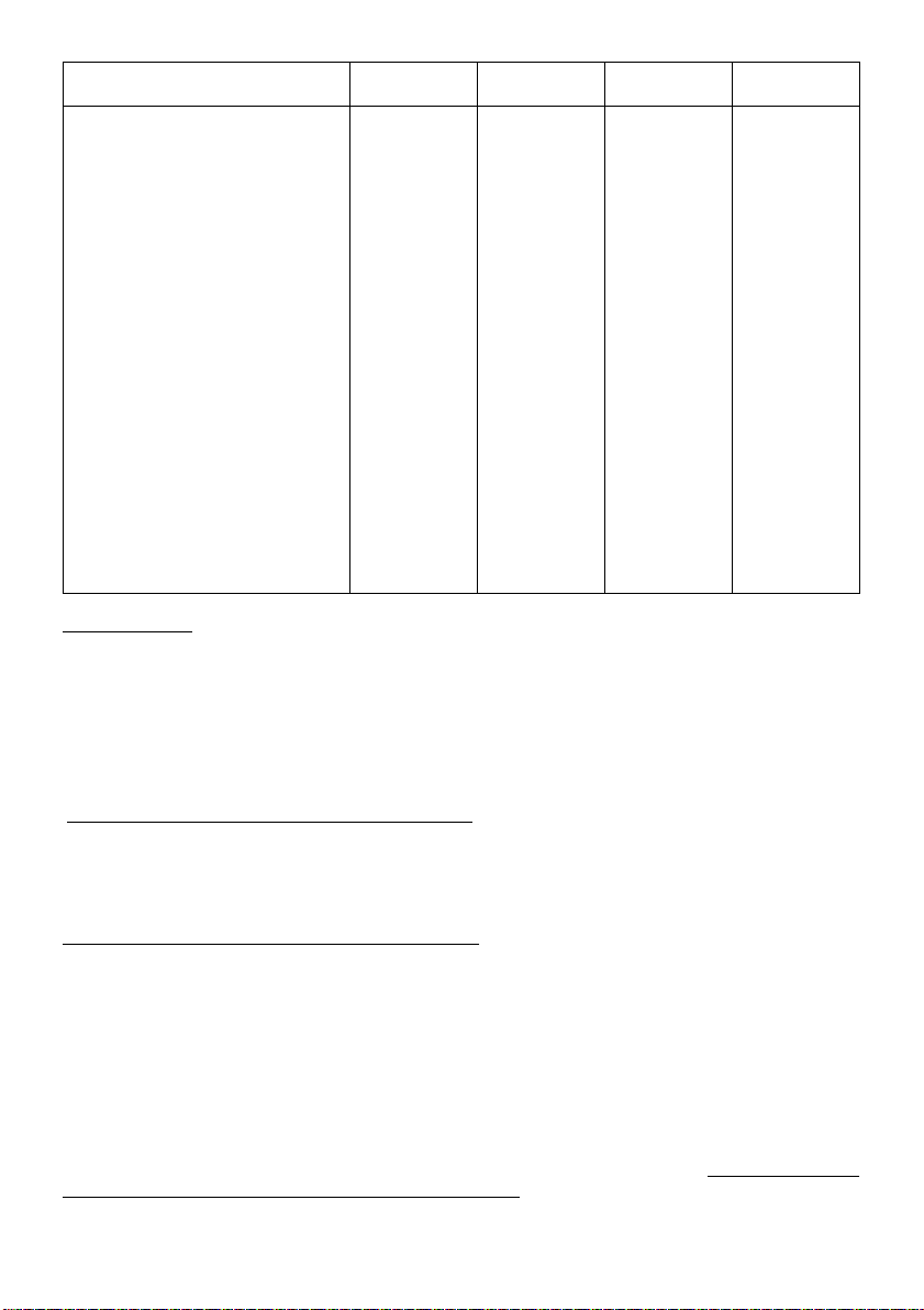
Technische Daten/Technical Data
EA-PS 2016-050
EA-PS 2016-100
EA-PS 2032-025
EA-PS 2032-050
Eingangsspannung/
-Netzfrequenz /
Ausgangsspannung/
-Stabilität/
-Stabilität ±8% U AC/
-Restwelligkeit/
Ausgangsstrom/
Anzeige
/Display
Temp.koeffizient/Temperature coefficient
Lagertemperatur/
Betriebstemperatur/
Abmessungen BxHxT/
Gewicht/
Weight
Artikel Nr./Article Nb.
Input voltage
-Mains frequency
Output Voltage
Stability
0...100% Last/
Stability
Ripple
Output current
Spannung/
Strom/
Voltage
Current
Storage temperature
Operating temperature
load
±8% V AC
Dimensions WxHxD
230V ±10%
50...60Hz
0...16V
<20mV
<3mV
<4mVp-p
0...5A
±(1%+2Digit)
±(1%+4Digit)
500ppm/°C
-25...70°C
0...40°C
210x132x255mm
5,25kg
39 200 100
230V ±10%
50...60Hz
0...16V
<40mV
<3mV
<4mVp-p
0...10A
±(1%+2Digit)
±(1%+4Digit)
500ppm/°C
-25...70°C
0...40°C
210x132x255mm
5,9kg
39 200 101
230V ±10%
50...60Hz
0...32V
<10mV
<5mV
<4mVp-p
0...2,5A
±(1%+2Digit)
±(1%+4Digit)
500ppm/°C
-25...70°C
0...40°C
210x132x255mm
5,25kg
39 200 102
230V ±10%
50...60Hz
0...32V
<20mV
<5mV
<4mVp-p
0...5A
±(1%+2Digit)
±(1%+4Digit)
500ppm/°C
-25...70°C
0...40°C
210x132x255mm
5,9kg
39 200 103
Inbetriebnahme
Vor der ersten Inbetriebnahme des Gerätes muß das Gehäuse, die Bedien- und Anzeigeelemente sowie
das Netzkabel auf Beschädigungen hin untersucht werden. Vor jedem Öffnen des Gerätes muß unbedingt
der Netzstecker gezogen werden. Eine Reparatur, Wartung oder Kalibrierung des Gerätes darf nur durch
eine Fachkraft erfolgen.
Das Gerät darf nur an eine Schutzkontaktsteckdose mit 230V 50/60Hz angeschlossen werden. Die
natürliche Luftzirkulation darf an den Luftschlitzen und Kühlkörpern nicht behindert werden.
Die Netzsicherung befindet sich auf der Rückseite des Gerätes über dem Netzeingang. Um diese
auszuwechseln, muß das Gerät vom Netz getrennt werden!
Vor dem Öffnen des Gerätes Netzstecker ziehen!
Der Anschluß der Verbraucher erfolgt an den mit + und – bezeichneten Ausgangsbuchsen.
Serienschaltungen über 300V sind nicht statthaft, da es sonst zu Isolationsproblemen kommt.
INSTALLATION / INSPECTION AFTER UNPACKING
Before taking the unit into operation it is necessary to inspect the housing, the controls etc. for signs of
physical damage. Save all packing materials until the inspection is completed. If damage is found, notify
the carriers immediately. Our authorised representative also should be notified.If any physical damage
has been found, the equipment should not be connected to the mains.
DO NOT OPEN THE UNIT BEFORE THE PO WER CABLE IS DISCONNECTED FROM THE MAINS V OL T A GE!
Servicing, repairs or calibrations should only be carried out by trained engineers. The unit may only be
operated using a properly wired and grounded mains plug as the grounding of the unit follows via the
earth wire of the power cable. The unit must be operated only on the voltage stipulated on the type plate .
The mains fuse is located on the rear of the unit above the mains input. If it is necessary to change the
fuse, the unit must be disconnected from the mains! It is imperative that the fuse is only be replaced
by one of same value and physical dimensions as the original supplied fuse. The unit must be
disconnected from the mains whilst replacing the fuse.
The load must be connected to the plus (+) and the minus (-) sockets on the front. Check for correct
polarity.
© EA-ELEKTRO-AUTOMATIK , D-41747 Viersen , Helmholtzstr. 31-37, ☎ 02162-3785-0, FAX. 02162-16230
2

Bedienelemente Frontplatte
Operating Elements Frontpanel
12
3 4 5678
1 Voltmeter, Ausgangsspannung
2 Amperemeter, Ausgangsstrom
3 Netzschalter Ein/Aus
4 Spannungseinsteller
5 Stromeinsteller
6 Ausgangsbuchse + , (rot)
7 Erdungsbuchse
8 Ausgangsbuchse – , (schwarz)
© EA-ELEKTRO-AUTOMATIK , D-41747 Viersen , Helmholtzstr. 31-37, ☎ 02162-3785-0, FAX. 02162-16230
1 Voltmeter, Output voltage
2 Ammeter, Output current
3 Mains switch, ON/OFF
4 Voltage adjustment
5 Current adjustment
6 Output socket + , (red)
7 Earth socket
8 Output socket – , (black)
3

Labornetzgeräteserie EA-PS 2000
Allgemeines
Wesentliche Merkmale dieser Geräteserie sind ausgereifte Technologie, kompakter Aufbau und ein
breites Typenspektrum. Die Geräte können als Konstantspannungsquelle mit Strombegrenzung oder als
Konstantstromquelle mit Spannungsbegrenzung eingesetzt werden.
Strom und Spannung sind kontinuierlich einstellbar. Für hohe Zuverlässigkeit, auch unter extremen
Bedingungen, sorgen eine automatische Trafoumschaltung, Power-MOS-FET-Endstufen und eine temperaturabhängig gesteuerte Lüfterleistung mit Funktionsüberwachung. Das Gerät ist ohne Lüftungsöffnungen auf Ober- und Unterseite konzipiert und hat keine außenliegende Kühlkörper.
Anzeigeinstrumente
Die Geräte besitzen getrennte digital anzeigende LED Volt- und Amperemeter.
Überlastschutz
Der Ausgang ist dauerkurzschlußfest. Der Strom läßt sich von 0 bis zum Nennstrom kontinuierlich
einstellen.
Parallel- und Serienschaltung
Es können zwei oder mehrere Geräte in Serie oder parallel betrieben werden. Bei Serienschaltung ist
darauf zu achten, daß die maximale Ausgangsspannung aus Isolationsgründen unter 300V bleibt.
Hinweis:
Unsere Geräte werden ständig weiter entwickelt und dem Stand der Technik angepaßt. Aus diesem Grund kann das Gerät im Vergleich
zu dem in dieser Anleitung beschriebenen Gerät leichte Änderungen aufweisen. Nur Daten mit Toleranzen oder Grenzen können als
garantierte Werte betrachtet werden. Zahlen ohne Toleranzen haben nur informatorischen Wert und werden nicht garantiert.
Laboratory Power Supplies EA-PS 2000
General
Main characteristics of this series are state of the art technology, compact design and a wide type spectrum.
The units may be used as constant voltage supply with current limiting or as constant current sources
with voltage limitation. Current and voltage are continuously adjustable by means potentiometers on the
front panel.
High reliability - even under most extreme conditions - is provided by automatic transformer switching,
MOS-FET power stages and a temperature-controlled ventilation regulation with functional monitoring.
The unit is designed without ventilation slots at the top and the bottom and has no external heat sinks.
Indication Instruments
The units are equipped with separate digital LED volt- and ammeters.
Operation in Parallel or Series
It is possible to operate two or more units in series or in parallel. In series operation the maximum allowed
voltage is 300V because of isoltaion problems abov e this voltage.
Notice
The continuing development of our products can be the reason that the unit described in this manual may be slightly diff erent from the one
being delivered. Only data with tolerances or boundaries are guaranteed. Data without tolerances are for inf ormation only and not guaranteed.
© EA-ELEKTRO-AUTOMATIK , D-41747 Viersen , Helmholtzstr. 31-37, ☎ 02162-3785-0, FAX. 02162-16230
4
 Loading...