

Page 1

TYRO129
QUICK START GUIDE (DIY)
Page 2

TY R O12 9
QUIC K START GUI DE
Package Included:
1 x frame kit
2 x 2507-1800KV brushless motor CW
2 x 2507-1800KV brushless motor CCW
1 x 4In1 40A BLHeli_S ESC
1 x F4 Flight Controller
1 x Caddx.us Turbo f2 Camera
1 x 5.8G 40CH 25/100/200/600mw switchable VTX
Antenna
1 x
1 x BN220 GPS Module
2 x 7065 3-blade propeller CW
2 x 7065 3-blade propeller CCW
1 x Antenna Fixing Seat Mount 3D Printing
1 x Gopro Fixing Seat Mount 3D Printing
Anten na
Caddx .u s Turbo
f2 Came ra
7056 3- bl ade pro pe lle r
-2-
Switc ha ble VTX
F4 Flig ht C ont ro ll er
4In1 40 A
BLHel i_ S ESC
2507 18 00 KV 3-6S
Brush le ss Mo to r
Bn220 G PS M odu le
Page 3

TY R O12 9
Contents
1.0 Frame kit----------------------------------------04
Motor-----
2.0 ----------------------------------------04
3.0 Esc------------------------------------------------05
4.0 Flight controller---------------------------------06
5.0 Camera-------------------------------------------07
6.0 Switchable VTX------------------------------------07
7.0 Antenna------------------------------------------08
8.0 Eachine BN-220 GPS Module----------------08
9.0 Screws--------------------------------------------08
10.0 Assembly drawing-----------------------------09
11.0 Adjusting parameter----------------------------10-11
QUIC K START GUI DE
-3-
Page 4
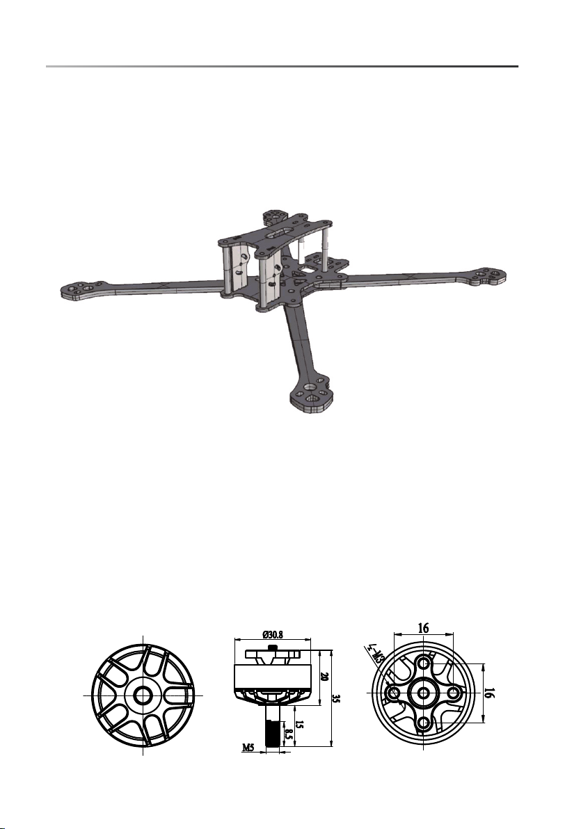
1.0 Frame ki t
Wheel base : 280mm
Frame arm th ickness: 5mm
Bottom pla te thickness: 2mm
Side plate t hickness: 1.5mm
Frame kit ma terial: 3K carbon fibe r
2.0 Motor
TY R O12 9
QUIC K START GUI DE
KV: 1800KV
Lipo cell: 3 -6S
Weight: 39g
Whole shaf t length: 35mm
Maximum pu ll: 1488g (4S 7inch p ropeller)
Maximum po wer: 840W
Configu- ration: 12N/14P
Mounting h oles distance: 16 *16mm
Mounting h oles: φM5
Recom men d propeller: 6-7 in ch
-4-
Page 5
TY R O12 9
QUIC K START GUI DE
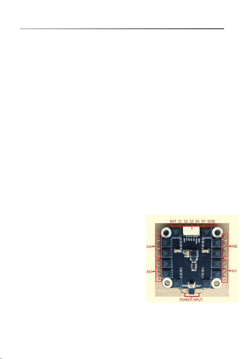
3.0 ESC
Continuo us current: 40A
Peak curre nt: 45A (10S)
BEC output : no
Input volt age: 2-6S
Main contr ol chip: 48mhz EFM8BB2
Firmware u pgrade: Support s Dshot150-600/Mul tishot/Oneshot/P WM
Size: 37.5 x37.5mm
Mounting H ole: 30.5x30.5m m
Features :
High-performance EFM8BB 21F16G microproces sor with operating
frequenc y up to 48MHz;
Japan's Toshiba 5×6 packa ge MOSFETs are more reliab le than 3×3
package MO SFETs;
6-layer hi gh TG 3OZ coppe r-thick PCB board, whi ch greatly reduces
heat gener ation and is more efficient;
Use the BLHe li_S open source pr ogram to upgrade the fir mware or
change the E SC parameters via t he throttle signal lin e to support all
BLHeli_S functions;
ESC can supp ort DShot150/30 0/600 digital thrott le mode and common
PWM, OneSh ot125, OneShot42, Mu ltShot throttle mode;
Built-in 5 V@2A BEC, can supply p ower for flight contro l, camera,
image tran smission, LED lig hts, etc.
Interfac e definition chart:
BAT: power positive electr ode;
GND: power n egative electro de;
5V:5V regulated p ower supply
output int erface,maximum current 2A;
S1-4: thro ttle signal input interface,
S1 corresp onds to M1.S2 corresponds
to M2, S3 corr esponds to M3, S4
correspo nds to M4.Number el ectric
adjustme nt;
POWER INPU T: power line pads, "GND"
correspo nding power suppl y.The line
negative p ole, "BAT" cor responds to the
positive p ole of the power supp ly line.
-5-
Page 6
TY R O12 9
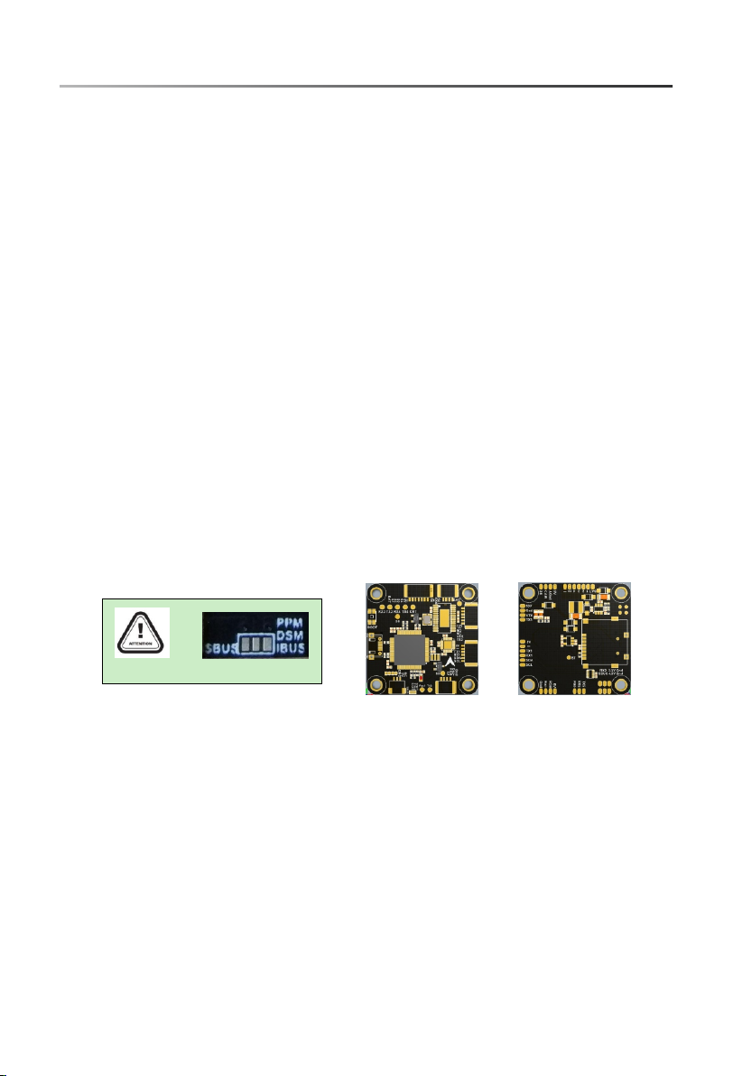
4.0 Flight c ontroller
Flight Con trol Name: EACHINE F4 Fl ight Controller
Size: 37 × 37m m
Mounting h ole: 30.5 × 30.5mm
Firmware v ersion: MATE KF405
5V: 5V regulated po wer supply output inte rface,
maximum cu rrent 2A (non-flyi ng control, need to
use Eachin e BLHeli_S 40A 4in1 ES C)
4.5V: Receiver po wer interface (volta ge only when
USB is power ed)
3.3V: 3.3V output ( requires flight cont rol to input 5V
before out put)
NC: floati ng pin, no network co nnected
CRT: current monitoring p ort
S6, DAC: cam era tuning pin (sel ected according to
the flight c ontrol firmware version)
CAM: camer a input interface
VTX: graph t ransmission out inte rface
RGB: RGB lig ht strip interface
Buz-: conn ect the buzzer negative pole, positive po le
to 5V
TX2: Recei ver SmartPort interf ace
Rssi: Rssi s ignal input port
QUIC K START GUI DE
Not e: Be sure t o solde r the rec eive r protoc ol sel ection p ad
Introduc tion to Flight Control:
168MHz STM 32F405 main contr ol chip, can run higher ra te PID;
The SPI bus mo de MPU6000 gyroscope provides fast resp onse
time and exc ellent shock abso rption;
Onboard OS D chip, you can use BetaFl ight assistant so ftware to
adjust par ameters;
Onboard Bo sch BMP280 high pre cision barometer;
MicroSD Bl ackBox;
Reserve 5 se rial ports and I2C in terface for easy GPS acc ess;
Onboard 10 V BEC provides a clea ner image display for im ages;
Reasonable layout, accord ing to the installatio n requirements of
most of the fl ying hands, put the func tional pads toget her to avoid
jumpers;
All interf aces are availabl e in socket and pad option s and are suitable
for different groups of p eople;
-6-
Page 7
TY R O12 9
QUIC K START GUI DE
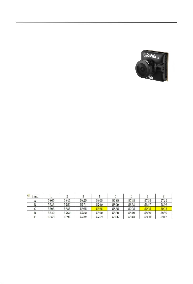
5.0 Camera
Case size: 1 9x19x16mm
Weight: 5.5g
Signal sys tem: NTSC / PAL (Switchabl e)
Resoluti on ratio(horizo ntal center): 1200TV L
Video output Signal: cv bs
Image: 16: 9
Synchron ization method: i nter-sync
Camera len s: standard 2.1mm
Lens opera ting voltage: DC 4. 5-40V
S/N Ratio: > 52dB (AGC OFF)
Audio: YES
6.0 Switch able VTX
Output pow er & transmission distance: ≥0.5km@25m W,
≥1km@200m W, ≥2km@600mW
Transmitting po wer: 0mW/25mW/200m W/600mW
Full video f ormat: NTSC /PAL
Input volt age & power dissipa tion: 7V~24V, +12V/260mA@6 00mW
Size: 20*3 0*9mm
Weight: ≤7g(except ant enna)
With outpu t power self-check fun ction.
Nixie tube S CAN: frequency po int (1-8), frequency b and (A-E),
power (1-3 , 0=0mw, 1=25mw, 2=20 0mw, 3=600mw)
Frequenc y control method:
Button fre quency control (1-8): press the button fo r 2 seconds
to enter the f requency setting, an d press the button to change
the freque ncy CH1-8.Chang e the frequency band (A- E), set the
frequenc y, press the but ton for 2 seconds, then pr ess the button
to change th e frequency group F R (A-E).
Points for a ttention:
The antenn a is installed at the o utput terminal befor e power up,
so as not to dam age internal comp onents.Note that the i nput
voltage is w ithin the specifi ed range and is positive o r negative,
so as not to dam age internal comp onents.If the antenn a is replaced,
choose a sta nding wave and a good g ain antenna to obtain a lo nger
transmis sion distance.Attention should be pai d to electrostatic
protecti on during transpo rtation and installa tion.
-7-
Page 8

TY R O12 9
7.0 Pagoda Antenna
Descript ion:
Brand name : Eachine
Item name: a ntenna
Quantity : 1 PC
Connceto r: RP-SMA Male
8.0 Eachin e BN-220 GPS Module
Brand Name : Eachine
Model: BN- 220
Item Name: B N-220 GPS+GLONASS Du al GPS module
- Built-in F LASH, TTL
Data Proto col: NMEA-0183
Output Rat e: 9600bps, 1HZ
Size: 22mm *20mm*6mm
1.TX LED:b lue.The data output, TX LED flashin g
2.PPS LED: red.PPS LED not bright w hen GPS not fixed,
flashing w hen fixed
9.0 Screws
QUIC K START GUI DE
8xM3*8
12xM3*8
4xM3*12 4xM3*14
-8-
Page 9

10.Assem bly drawing
TY R O12 9
QUIC K START GUI DE
-9-
Page 10

TY R O12 9
11.Adjusting paramet er
1.Click co nnect connectio n
2: Click the R X interface under UART2 under the por ts option,
as shown in th e figure.
3: Click CON FIGURATIN to change to dshot600.
QUIC K START GUI DE
4: Click CON FIGURATIN; change to SBUs
5: Click mod es, add arm and angle , drag the slider betwee n 1300
and 1700, an d set arm to AUX1 and angl e to aux2
-10-
Page 11

TY R O12 9
11.Adjusting paramet er
6: Push the sl ider to test the positiv e and negative rota tion of
the motor, su ch as error,
7: Click fon t manager, select be taflight, click uplo ad font
8: Click set up, calibrate accelerometer
QUIC K START GUI DE
-11-
 Loading...