

Page 1
NOVIC E-II 1-2S Bru shles s Micro Drone
NC1206
NC1206
NC1207
It em
120mm t oo th pi ck frame
NanoX F4F S V1 .0 f light contr ol le r
Eachi ne N C1 10 3 KV 85 00
HQPRO P T6 5 bi -b lade prop el le r
Caddx E OS 2 v2 v er si on 4 :3
VT X: 5.8g 25mw~ 20 0m w sw itchabl e Wh oo p VT X
3.8v 46 0m ah b attery
6in1 6- wa y LI PO /L IH V Charg er
FS- I6 2 .4 G ra di o transmitt er
Eachi ne V R0 09 5 .8 G 40 CH goggles
Pro pe ll er d is assemble to ol
Screw dr iver
LED&Buz ze r PC B to p board
M2*D3 .5 *L 20 A lu mi num Alloy col um n
Dampi ng b al l
Batte r y mounted tra y
NC1201
NC1203
NC1205
NC1204
NC1209
NC1208
NC1210
NC1211
NC1212
Part N o. FLY M or e
NC121 0
NC120 4
NC120 5
NC120 6
NC120 7
NC120 3
NC121 2
NC120 1
NC120 8
NC120 9
NC121 1
RT F
1
1
4
2
1
1
2
1
1
1
1
1
1
4
4
2
1
1
4
2
1
1
10
1
1
1
1
1
1
4
4
2
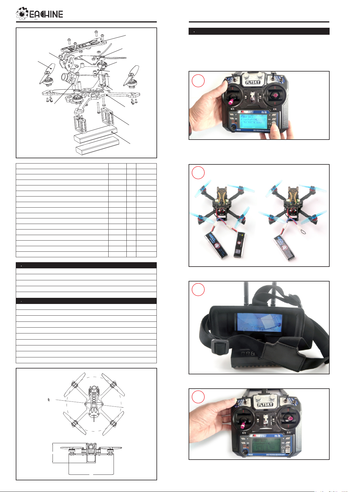
3 St ar t F PV F li ght
Star t by pow eri ng on your Rad io and Goggles. NOVI CE-II com es alread y bound
to your radi o and on the right vid eo channe l matc hed with your gog gle s. Powe r
on NOV ICE -II by sliding th e battery into the batter y tray and plu ggi ng it in . Once
the batter y is plu gge d in, set NOVI CE- II on a stable surf ace so it can calibrate .
Calibratio n take s a few second s then NOVI CE-II is rea dy to fl y.
1
Install 4 x AA 1 .5 v batter y to the radio and pu sh t he p ow er switch t o tu rn o n
the rad io . If t he t hrottle sti ck w as n ot a t th e bottom po si ti on t he r adioter w il l
alarm .
2
Power w it h 2S batter yPower w it h 2S batter yPower w it h 2S batter y
Power w it h 1S batter yPower w it h 1S batter yPower w it h 1S batter y
1 Spe c if ic at io n
Brand Name : Eachi ne
Item Name: NOV ICE -II 1-2 S Tooth pick RTF & Fly more
Wheelba se: 120mm
Size: 100m m*100mm*40mm
Weig ht: 50g (wi tho ut battery)
2 Fea tu re s
Nano X F4 p ro f li ght con tr ol ler
Power fu l an d smoot hl y
Led Str ip r ea dy
Built -i n Bu zzer
New des ig n 1103 K V8 50 0 mo tor s
Camer a Ang le a djust ab le
VTX p ow er s wi tchab le 2 5m w~200 mw
Sma rt au di o ready , c ha ng e VTX ban ds , po wers, c ha nn el s via O SD
Ready t o fl y
Compa ti bl e both fo r 1s -2 s Lipo/ LI HV
120
Connect t he b at tery f or t he N OV ICE-II
3
. Turn o n th e Vr0 09 g oggles and ch ec k th e Vi de o
4
43
Toggl e SWA (AU X1 ) swi tch to ar m the N OV ICE-I I , you wil l find "A RMED" n otice
99
in th e scree n of th e Goggl es. Recomm en d Toggl e SWC(AUX2) to c hoose Stab le
mod e for the b eginn er. Ha ppy fli gh t and keep it sa fe.
-1-
Page 2
5
Pos iti on 1 Ac ro m od ePos iti on 1 Ac ro m od e
Pos iti on 1 Ac ro m od e
Pos iti on 2 St ab le m od ePo si ti on 2 St ab le mo de
Pos iti on 2 St ab le m od e
Pos iti on 3 Ai r mo dePos iti on 3 Ai r mo de
Pos iti on 3 Ai r mo de
Toggle SWC(AU X2 ) sw itch to s el ec t fl ight mode (De fa ul t is A cro mode)
4. Ch ar g er t he L ip o Ba tt er y
Charg in g cu rrents sw it chCharg in g cu rrents sw it chCharg in g cu rrents sw it ch
4.2V/4.35V charging switch
DC 12V In pu t
2-6S Li po I np ut
NOVIC E-II 1-2S Bru shles s Micro Drone
Im port an t no ti ce :
1. Th e belowin g conte nt a re re ga rding t he adva nced tu to rial. T he dron e
com es o ut alre ady fin is hed all t he sett in gs and bo un d with th e radio .
2. Do n't mod to X T3 0 Plug , it w ill bur nt t he flig ht contro ller if m od to xt3 0
and u se high dis charg e ra ting ba tter y .
6. Flight contro ll er c on ne ct ion diagram
GND
LIPO_IN
+5V
Video_i n
Video_o ut
M4
M3
USB
TX1
GND
M1
RX1
IR1
LIPO_IN
1-2S
M2
USB
M3
GND
M4
+5V
Video_i n
Video_o utVideo_o utVideo_o ut
BUZZ+
BOOT
LED
BIND
+5V outpu t
GND
GND
TX2
RX2
BUZ-
BUZ-
TX2
LED
M2
M1
GNDGNDGND
BIND
BOOT
Solid LED -- -C ha rging
USB 5V ou t
LED OFF-- -C ha rging compl et e
Por ts a re n umbered 1 -6 . Do n ot p ut m ore tha n on e ba tter y on a s in gl e
port . Fo r example: do n ot i ns er t one ba tt er y on t he P ic ob la de 1.25 plug
and ano th er o n th e sa me p or t wi th t he P H 2.0 plug.
5. Fl ig ht a nd Ra di o St ic k Co nt ro ls
Alway s us e ca ut io n wh en flying and o pe ra te i n an o pen and contr ol la ble area.
Please le ar n th e fl ig ht contro ls f ir st b ef ore power in g on t he a ircraft to fl y. Th e
left stick cont ro ls t hrottle a nd y aw d irection of N OV IC E-I I. T he r ig ht stick
contr ol s pi tch and rol l of the airc ra ft .
Left Stick Diagram
Throttle up
Yaw Left
Climb
Left Side View
Nose Yaws Left
Throttle down
Yaw Right
Descend
Nose Yaws Right
Left Side View
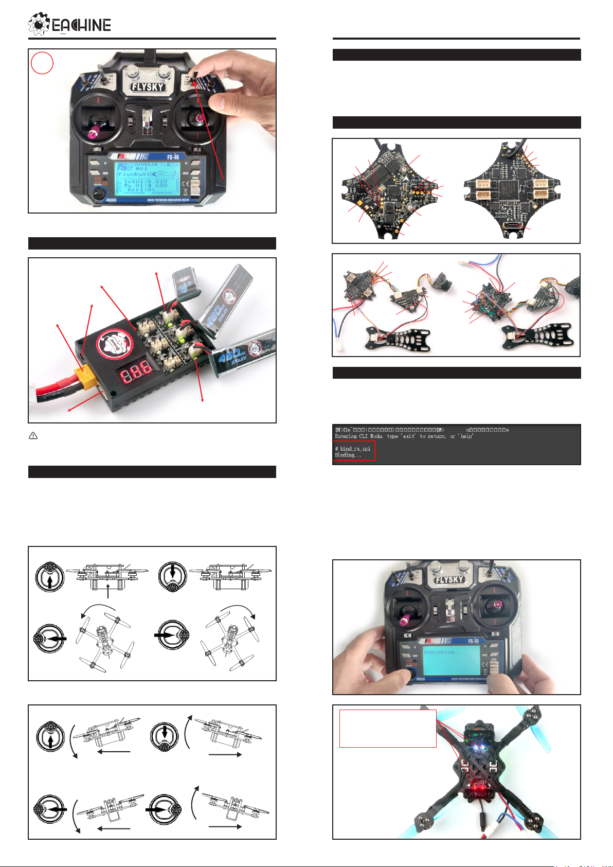
7. Binding pro ce du re
1.Plu g th e us b an d go t o the CLI comma nd t ab i n th e be taflight co nf ig ur ator,
then ty pe “b in d_ rx_s pi”, th e re ceiver wi ll g et ti ng i nto bind mode , a nd t he n
make yo ur F lysky radio to bi nd m od e.
2.Pleas e En su re the RX setup o f yo ur transmit te r is i n AF HD S 2A Mode. Then
get you r tr an sm it ter into bi nd in g mo de : Turn o n th e tr ansmitter w hi le
holding t he b in d bu tton. The Whi te a nd red LED on the f li gh t co nt roller
should bl in ki ng f as t first and then bl in ki ng s lo wl y, th is indicate s bi nd in g
succe ss fu ll y. No w you need to e xi t bi nd in g mode of t he t ra ns mi tter and
re- co nn ec t th e Novice-II t o th e co mp uter, th en t he Re d an d wh it e LED should
be gettin g to b e so li d , this indica te s th e co nnection wa s es ta bl is he d between
the NOVIC E- II a nd y our transmitt er.
Right Sti ck Diagram
Pitch Down
Rol l Lef t
Left Side View
Forward
Rea r Vie w
Lef t
Pitch Up
Rol l Rig ht
Backward
Rig ht
Left Side View
Rea r Vie w
-2-
-Solid: N or ma l wo rk
-Blinki ng f as t: B in d mode
-Blinki ng s lo wl y: B ind
succe ss fu l or n o RC Signal
Page 3

NOVIC E-II 1-2S Bru shles s Micro Drone
8. Re ce iver c on fi gu ra ti on
Please se t Receive r mo de t o be S PI RX Suppor t from the Co nf ig ur at io n tab of
the Bet af li gh t Co nf igurato r, th en select A71 05 _F ly sk y_ 2A Prov id er f or
AFHDS -2 A Pr otocol Radi o tr an sm it ter or Sele ct A 71 05 _F ly sky Pro vi de r fo r
AFHDS P ro to col Radio tra ns mi tt er, do n't e na bl e Se ri al RX since the F li gh t
contr ol le r is i ntegrat ed S PI B US Re ce iv er
9. VT X Ba nd s an d Cha nn el s se tu p
LED 5 LED 8
591 7MHZ
+5V o ut put
Fre qu en cy an d ch ann el f re qu en cy ta bl e
FR
Ban d1
Ban d2
Ban d3
Ban d4
Ban d5
BAN D5
Cam _IN
GND
CH8
Swi tch But ton
GND
CH
CH1
586 5M
573 3M
570 5M
574 0M
565 8M
25M W
BUZ Z+
CH2
584 5M
575 2M
568 5M
576 0M
569 5M
100 MW
CH3
582 5M
577 1M
566 5M
578 0M
573 2M
U.F L
200 MW
Blu e Video _out
CH4
CH5
580 5M
578 5M
579 0M
580 9M
566 5M
588 5M
580 0M
582 0M
576 9M
580 6M
Ban d LED
Cha nnel LE DCha nnel LE DCha nnel LE D
CH6
576 5M
582 8M
590 5M
584 0M
584 3M
1,2 ,3,4, 5
8,7 ,6,5, 4,3,2 ,1
Bla ck GND
Red + 5V In put
Gre en smar e Aud io
Yell ow Vi deo_I N
CH7
574 5M
572 5M
584 7M
586 6M
590 5M
590 5M
586 0M
588 0M
588 0M
591 7M
CH8
Notes:
Default vtx setting is 200mw but the VTX power LED indicate will always show 25mw
when the quad was disarmed, because we have "set vtx_low_power_disarm=on"
There are 3 ways to switch the vtx channels:
1.S hort press to choose the VTX channel, press and holding the button to Choose the
VTX Band (Can't save , it will lost the channel while power off)
2. Go to Betaflight CLI ,type the command:
Set vtx_band=3
Set vtx_channel=1
Set vtx_freq=5705
save
Notes: The vtx_freq should match the vtx_band and vtx_channle as the VTX Channel
list shows.
For example, if you set vtx_freq=5732, you should set vtx_band=5 and
VTX_channel=3
3.E nable Smartaudio for UART2, then move the stick of the transmitter (THR MID+
YAW LEFT+ PITCH UP) to enter OSD Menu, Enter to Features, then enter to VTX SA
to set VTX Band and channel
10 .G og g le s an d VT X Re ce iv er ch ann el s et ti ng
9
8
7
6
5
1
2
3
4
Descrip ti on :
Key 1: Short press for MENU mode; Long press (More than 3 sec) for Power ON/OFF.
①
Key 2: Short press for Auto-Searching (Automatic selection of the strongest channel).
②
Key 3: Short press for Band+ (Change bands A-B-E-F-R circularly).
③
Key 4: Short press for Channel+ (Change channels 1-2-3-4-5-6-7-8 circularly).
④
Micro-USB Charging port: Supports DC5V only.
⑤
Antenna port B: RP-SMA male.
⑥
Charging indicator: Red light when charging light; full power, the indicator goes off.
⑦
Antenna port A: RP-SMA male.
⑧
AV Jack: In RF receiving mode can output AV signal; In AV mode can enter the video
⑨
signal.
Menu Oper at io n In st ru ct ions:
In norm al m od e, p ress Ke y 1 to e nt er the MENU mod e.
In MENU mod e:
Key 1 : Se le ct t he o ption bar.
①
Key 2 : Return to n or ma l mo de.
②
Key 3 : Val ue -.
③
Key 4 : Val ue +.
④
Freq ue nc y (5 .8 GH z) :
Band
A
B
E
F
R
CH1
5865
5733
5705
5740
5658
5845
5752
5685
5760
5695
CH3
CH4
CH5
CH6
5825
5771
5665
5780
5732
5805
5790
5645
5800
5769
5785
5809
5885
5820
5806
5765
5828
5905
5840
5843
CH7
5745
5847
5925
5860
5880
CH2
11 .M ix er t yp e an d ES C/m ot or p ro to col
Firmwar e up da te
Props IN
Fix the CW propeller onto t he M 1
and M4 motor (CW moto rs)
Fix the CCW p ro pe ll er s on to t he M 2
and M3 motor (CCW m otor s)
12 .D ef au lt P ID s ett in g an d cu r re nt s se tti ng
CH8
5725
5866
5945
5880
5917
-3-
Page 4

1、Handl e
2、Anten na
3、Swi tc h A( arm and disar m)
4、Swi tc h B
5、Swi tc h C( Mode switch )
6、Swi tc h D
7、Lef t st ic k
8、Left tr im
9、Right t ri m
10、Righ t st ic k
11、Left t ri m
12、Righ t tr im
13、Up
14、pres s th e En ter key
15、Down
16、Shor t press the Cance l ke y
17、Code k ey s
18、Sw it ch
19、LC D Di splay
NOVIC E-II 1-2S Bru shles s Micro Drone
16 .E SC C he ck a nd F las h fi r mw ar e13 .R ad io c ha nn el s/S wi tc h an d Be ta fl ig ht m ode s et ti ng
1. Down lo ad N ew releas e Bl he li su ite fro m:
https :/ /w ww. me di af ire.c om /f ol de r/ dx6kfaasy o2 4l /B LHeliSuite
2. Connec t th e NO VI CE -II flight co nt ro ll er to compu te r
3. Op en the De vice Ma nager of you r compu ter, find the Po rt s, plea se make sure
the C om port Ser ial Num be r is un der 255 , other wise it w ill can' t conne ct to the
BLH EL ISUIT E. You can ch ange th e port seri al numb er like the be llowi ng step :
14 .AUX C ha nn el s et u p
15 .L ED S tr ip S ett in g
4. Open the B LH EL IS UI TE, Select SI L ABS BLHeli Bo ot lo ader (Cleanfl ig ht ) from
the thi rd t ab o n th e top side. T he n Se le ct t he right Serial c om p or t and Cl ic k
connect . You can also F la sh t he n ew release BL He li _s f ir mware v ia t he
BLHEI LI SU IT E, t he f irmware Tar ge t is “ S-H-50”
Fir mware t arget
Fla sh firm ware
17 .F li gh t con tr ol le r fi r mw ar e u pd at e
1. Install latest STM32 Virtual COM Port Driver
http://www.st.com/web/en/catalog/tools/PF257938
2. Install STM BOOTLOAD Driver (STM Device in DFU MODE)
3. Open Betaflight configurator and choose firmware target “CrazybeeF4FS”,
then select the firmware version.
4. There are 2 ways to get in DFU Mode: 1). Press and hold the boot button, then
plug USB to computer 2).loading betaflight firmware and hit “flash”, then it will
getting into DFU Mode automatically.
5. Open Zadig tools to replace the drivers from STM32 Bootloader to WINUSB Driver.
6. Reconnect the flight controller to the computer after replace driver done , and
open Betaflight Configurator, loading firmware and flash.
Cli ck chec k to see th e
det ails of t he 4in1 E SC
-4-
 Loading...