


IP-Link
Serial to Ethernet Converter
Instruction Manual
M 890-00556 rev. 01
REV. 01

IPLink
For technical support please contact
E2E Customer Support
at 1 (877) 626-8497
or email us at
support@e2eresolutions.com
E2E RESOLUTIONS
5200, Armand-Frappier
Saint-Hubert (Quebec)
CANADA
J3Z 1G5
E2E reser ves the ri ght to make alter nati ons to
speci fic ati ons, q uan tities, d imens ion s e tc. for
produ ction or other reas ons, subsequent to publi catio n. The information containe d herein has been
prepared by qualified experts within E2E. While we
believe the information is accurate and complete,
we make n o warranty or represent ation for any
part icular purpo ses. The information is offered in
good faith and with the understanding that any
use of the u nits or accessories in breach of the
direc tions and warnings in this doc ument is at the
sole di screti on and risk of the user.
2
IPLink, rev.01

IPLink
TABLE OF CONTENTS
1. PRECAUTIONS ..........................................................4
2. INTRODUCTION ........................................................4
3. ANTENNA INSTALLATION ..........................................4
3.1. Main Components of the Wireless System ....................4
3.2. Access Point & A-BOX Location ..................................5
3.3. Before Installing the Antennas .....................................6
3.4. Mounting Instructions ................................................8
3.4.1. Antenna Assembly & Connection ..........................8
3.4.2. Mounting a Short-Range Antenna ..........................8
3.4.3. Mounting a Long-Range Antenna ...........................9
4. IPLINK INSTALLATION .............................................10
4.1. Mounting Instructions .............................................10
4.2. Communication Cable ..............................................10
4.3. Connecting the IPLink Modules ..................................10
4.3.1. IPLink Cards .....................................................11
4.3.2. Merging the Ethernet Signals with a Switch ..........15
4.3.3. Connecting the PoE device .................................15
4.3.4. AC44 Card .......................................................17
5. TECHNICAL SPECIFICATIONS ...................................19
FOR CUSTOMER USE
Enter the serial number located on the
side of the module below for future
reference.
Model number:
Serial number:
IPLink
IPLink, rev.01
3

IPLink
1. PRECAUTIONS
The room temperature where the
mo dul e is loc ate d must always
remain between 32°F and 104°F
(0°C to 40°C).
To avoid exposing the module to
harmful gases or excessive humidity, it is preferable to install it in a
corridor.
Do not spray water on the module!
2. INTRODUCTION
The IPLink is a module that creates a bridge
between the controllers and the antennas.
It transforms the controller signals (RS-485)
into a nte nna -compatible E the rnet signals
(TCP-IP).
3. ANTENNA INSTALLATION
The A- BOX communicates with the controllers on site through W iF i antenna s. The
antennas must be installed outside, on the
highest point of the cornice of each building.
This section shows how to prepare and install
the antennas on top of your buildings before
connecting them to the controller network.
3.1. Main Components of
the Wireless System
The A- BOX work s wi th Omni- direc tiona l
Short-Range (SR) and Directional Long-Range
(LR) antennas. Each antenna is programmed
to act as a client (CL) or as an Access Point
(AP). In all, the system can use four different
types of antennas:
1) SR-CL 2) SR-AP 3) LR-CL 4) LR-AP
• Long- Ra ng e (LR) vs Short-R an ge ( SR)
Antenna
Short-Range (SR) antennas — Omnidirec-
tional antennas with a transmission range
of 1 mile (1.5 km). This type of antenna is
provided with the A-BOX wireless solution
and is used to link up the buildings on site.
Long-Range (LR) antennas — Directional antennas with a transmission range of 6 miles
(10 km). A Long-Range Access Point generally communicates with only one Long-Range
Client and it is not compatible with Shor tRange antennas. Long -Range antennas are
optiona l a nd require professional installation. For assistance, please contact your
E2E dealer.
4
IPLink, rev.01

IPLink
Access Point (AP) Antenna vs Client (CL)
Antenna
Access Point Antenna (AP) — The central ac-
cess point of the wireless network. In general,
there will be only one AP antenna per site.
Client Antenna (CL) — Antenna used to interconnect a client building to the access point.
• Component of an Antenna
Power over Ethernet (PoE) Device — The PoE
device passes electrical power, along with
data, over Ethernet cables. Each antenna
comes with its own PoE device.
Signal Strength Indicator — Each antenna
has status LEDs showing the signal strength
and power supply status.
3.2. Access Point &
A-BOX Location
Before installing your antennas, determine
the best place for the Access Point antenna
and the A-BOX. Best performance is achieved
when the following conditions are met (by
order of priorit y):
• Priority 1: Internet Access
The A-BOX system is located where direct
internet access is available.
A-BOX
Internet
Priority 2: Line of Sight
The Access Point (AP) antenna is located in
a place it can easily be seen by all Client (CL)
antennas (direct line of sight). This is gener-
ally the highest point on site.
CL CL
CL
AP
CL
Priority 3: Internet + Line of Sight
The A-BOX is located in the access point
building (on condition the direct internet ac cess is located in this building as well).
CL CL
CL
AP
A-BOX
Internet
CL
IPLink, rev.01
5

IPLink
3.3. Before Installing the Antennas
The following considerations should be taken
into account before installing the antennas.
Cable Length Limitation (1) — The Ethernet
cable between the antenna and the IPLink
must never exceed 300 feet (90 meters).
Cable Length Limitation (2) — The PoE device should be mounted no more than 2 feet
(1/2 m) from the IPLink module.
Wall Jack Required — A wall jack must be
located within 1.5 feet (460mm) of the UPS.
Battery Backup Required — To protect the
antenna against a power surge and electrical
fluctuations, the PoE device should be connected to the BATTERY SIDE of the Battery
Backup (UPS).
Protective Case Suggested — The PoE device
& battery backup (UPS) are not dust and
moisture proof. They should either be located
in a clean environment or placed in a dust &
water tight enclosure such as the optional
Medium White ABS Box.
Good Line of Sight Required — All antennas must be in direct line of sight with the
AP antenna. This direct line of sight is only
possible when all antennas have about the
same height above mean -sea-level. The area
around the visual line of sight must also be
clear from obstacle or else signal strength will
degrade. To increase the transmission range
of an antenna, raise it further above the roof
by mounting it on a pole.
Distance from Electrical Lines — The antenna
should be mounted at least 16 feet (5 m)
away from electrical lines.
6
IPLink, rev.01

IPLink
Electrical lines
16ft (5m) min
Antenna
Ethernet cable CAT5e
300 feet max
Medium White ABS Box
(opt.)
Ethernet 5e
2ft max
UPS
PoE
IPLink
Figure 1. Cable Limitations
1.5ft max
Wall
jack
IPLink, rev.01
7

IPLink
3.4. Mounting Instructions
3.4.1. Antenna Assembly &
Connection
1. Assemble the antenna as required (mount-
ing instructions may change depending on the
type of antenna in use).
2. Install the antenna on top of your building
as shown in sections 3.4.2 and 3.4.3.
3. Connect the Ethernet cable (outdoor rated)
of the antenna to the PoE connector.
The Ethernet cable coming from the
antenna must be curved downwards
right before it is connected to the PoE
device to avoid dripping condensation and water into the PoE device.
Refer to chapter 4.3.3 on page 15 to
complete the connections.
3.4.2. Mounting a Short-Range Antenna
Short-Range antennas are omnidirectional
antennas with a transmission range of 1 mile
(1.5 km). These antennas are provided with
the A-BOX wireless solution and they are
used to link up the buildings.
1. If needed, install a spacer on the cornice
to create a gap between the cornice and the
antenna (see example below).
2. Use the antenna bracket to fix the antenna
on the spacer and on the cornice.
Install the antenna upright.
8
IPLink, rev.01

IPLink
3.4.3. Mounting a Long-Range Antenna
Long-Range antennas are optional
and require professional installation.
For assistance, please contact your
E2E dealer.
Long-Range antennas are directional with a
transmission range of 6 miles (10 km). They
are primarily used to link up two distant sites.
Each Long-Range Access Point generally communicates with only one Long-Range Client.
1. Install the Long-Range antenna at least
8 feet (2.5m) above the top of the cornice.
We suggest using an 8-feet metal pole with
a diameter of 1.5 inches (38mm) to lif t it
(not included).
2. Solidly fix the antenna and pole to the
building with sufficient cabling.
LR antenna
(not included)
Cabling
(not
included)
Metal pole
Long-Range bracket
(included with
antenna)
8 feet (2.5 m)
∅ 1.5” (38mm)
IPLink, rev.01
9

IPLink
4. IPLINK INSTALLA-
TION
4.1. Mounting Instructions
Open the latch and lift the cover. Remove
the black caps located on each of the four
mounting holes. Mount the enclosure on the
wall using four screws. Be sure the electrical
knockouts are at the bottom of the enclosure
in order to prevent water from entering the
controller. Insert the screws in the mounting
holes and tighten. Fasten the four black caps
provided with the controller onto the four
mounting holes.
The enclosure must be mounted in a location
that will allow the cover to be completely
opened right up against the wall.
4.2. Communication Cable
Th e comm un ica ti on c ab le b et we e n the
controllers must be a twisted pair shielded
cable. The maximum length of the cable is
10,000ft (3,000m) and the recommended
wire diameter is 18AWG (1.0mm).
4.3. Connecting the IPLink Modules
The IPLink is a module that creates a bridge
between the controllers and the antennas.
It transforms the controller signals (RS-485)
into a nte nna -compatible E the rnet signals
(TCP-IP).
Also refer to the wiring diagram at
the end of this manual to connect
your IPLink module.
In a wireless application,an IPLink module
must be located in each building that uses
an antenna, except for the building where the
A-BOX is located.
Although IPLink modules are mos tly used
in wireless applications, they can also be
installed in an existing wired application that
uses Ethernet cables.
To enable the signal conversion, at least two
communication cards must be connected in
each IPLink module (see following sections).
10
When extending a wire, solder all
connections.
Never run low voltage cables parallel to high voltage wires to prevent
interference.
Cables must cross power cables at
a 90° angle. If this is not possible,
leave at least a 3-feet (11m) distance between the cables to avoid
interference.
IPLink, rev.01
IPLink
4.3.1. IPLink Cards
IPLink Cards allows the IPLink module to
conver t different kind of controller signals
into Ethernet signals. At least one IPLink Card
must be connected to each IPLink module.
Two models of IPLink Cards are currently
available: one is for the standard TC5/TC6/
Expert/Provision network and the other for
Feedlink network.
IMPORTANT:
A serial number is located at the
back of each IPLink Card. Write
down the serial number and location
of each IPLink card in use in
ANNEX1 of the A-BOX Installation
Guide. During the Commissioning
process, the A-BOX will refer to this
serial number to locate the wireless antenna(s) on site. Without this
number in hand, you will not be able
to associate the controllers with
their building.
• IPLink Card for Controllers
Description
If the A-BOX uses a standard TC5/TC6/Expert/Provision network, an IPLink Card must
be connected to each IPLink module on site.
Ethernet
connector
Figure 2. IPLink Card
Installation
1. Connecting the Ethernet Cable — Connect
an Ethernet cable to the IPLink Card and to
the L AN connecto r of the a ntenna’s PoE
device. If two IPLink Cards are connected to
the IPLink, use a switch to merge the signal
that goes to the PoE device.
Reset Procedure
To reset an IPLink Card:
1. Gently pull out the card from its connector.
2. Wait 10 seconds.
3. Plug the card back into the connector.
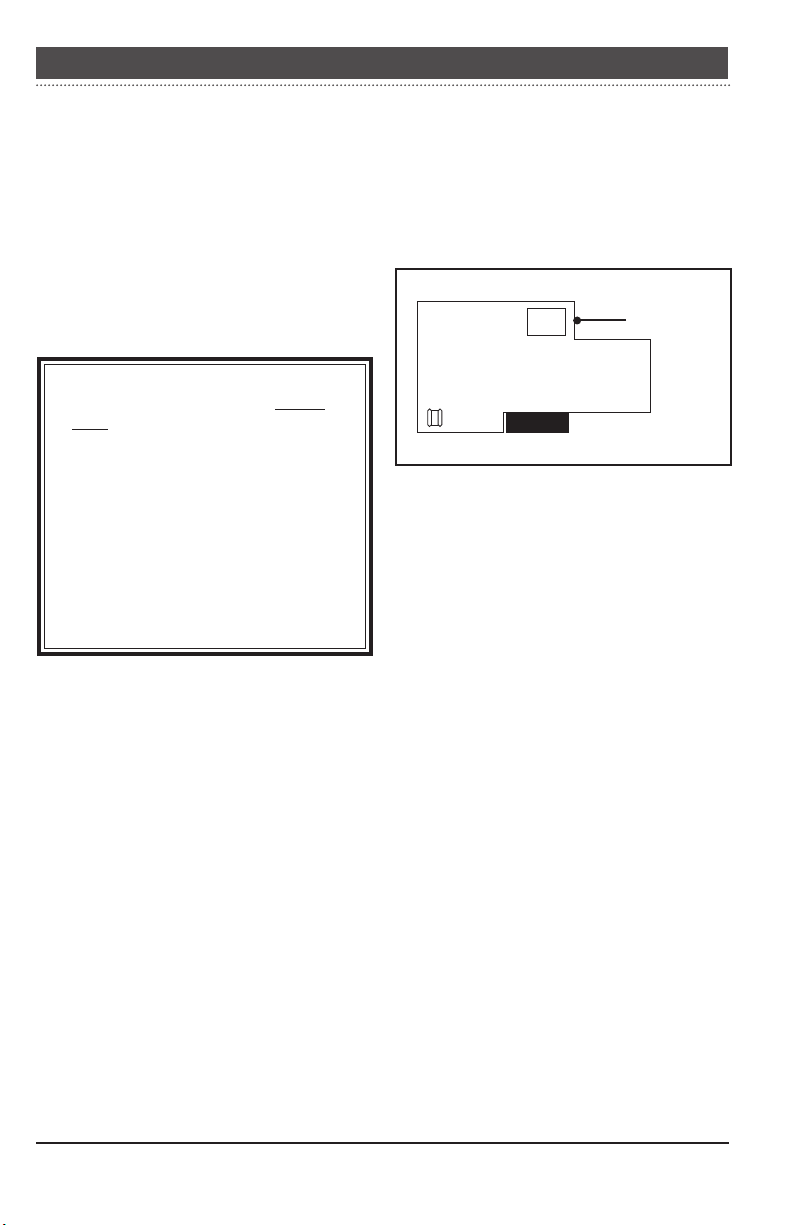
2. Connecting the Card — Plug the IPLink
Card into the CARD1 connector in the IPLink
module. Be sure to line up the ground connector with the metallic pin located on the
main board while inserting the card.
IPLink, rev.01
11
IPLink
Ethernet cable to
PoE device of the
antenna
Ground
connector
1
Figure 3. Installing the IPLink Card ( for controllers) in the IPLink
12
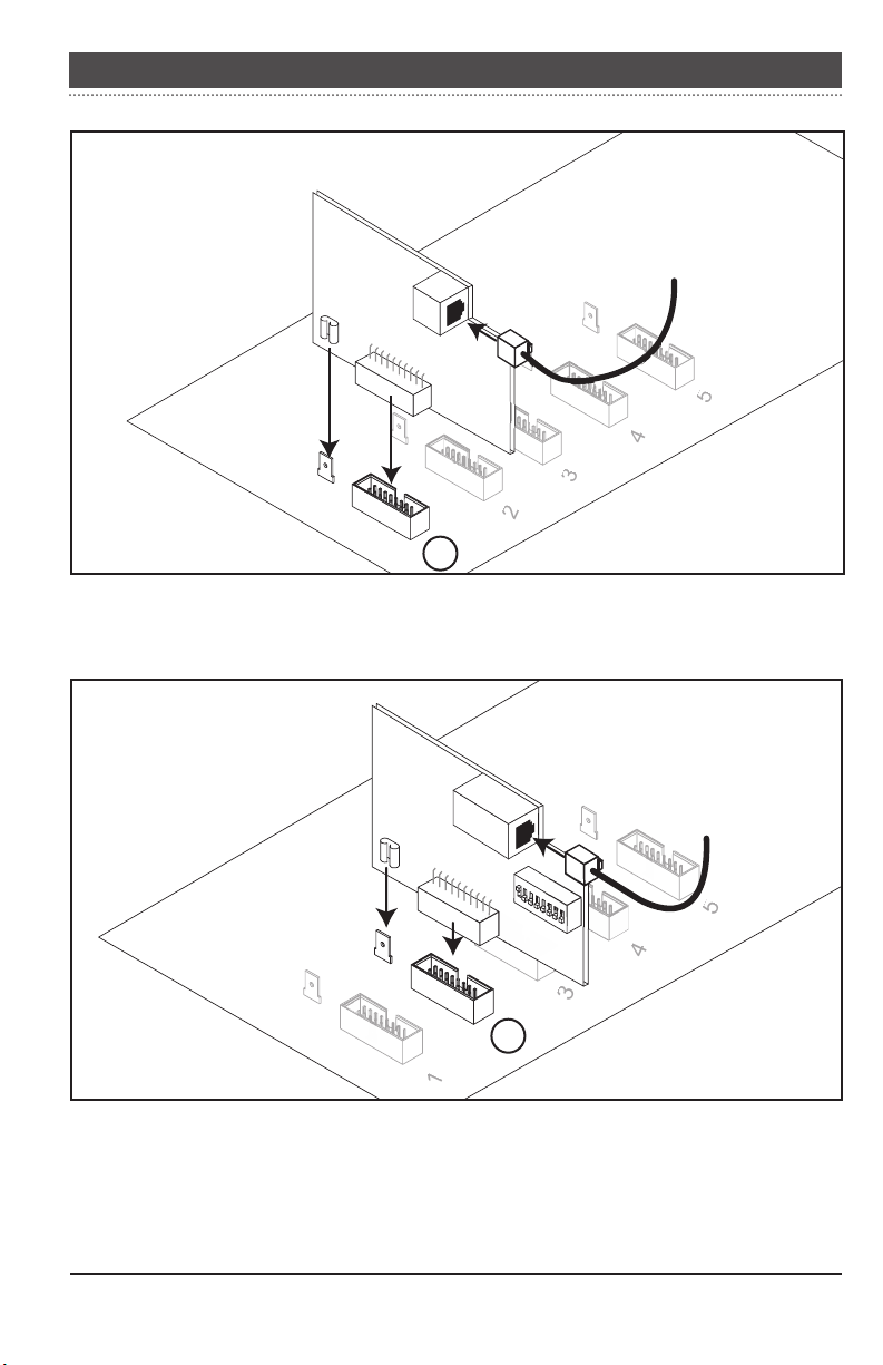
Ethernet cable to
PoE device of the
antenna
Ground
connector
2
Figure 4. Installing the IPLink Card ( for Feedlink) in the IPLink
IPLink, rev.01

IPLink
Status LEDs
2
1 3 4
Status LEDs
LED#Color Status Meaning
Ethernet connector
on the IPLink Card
1 Green Solid or
2 Red Solid or
3 Green Flashing Network activity
4 OFF Network speed = 10MB
flashing
flashing
Yellow Solid Network speed = 100MB
Card software has started
and loaded correctly
Software problem
IPLink, rev.01
13

IPLink
• IPLink Card for Feedlinks
Description
If the A-BOX uses a Feedlink network, an
IPLink Card for Feedlinks must be connected
to each IPLink module on site.
End of line selector
END OF LINE
J3
NOYES
Figure 5. IPLink Card for Feedlink Networks
Ethernet
connector
ON
OFF
1 2 3 4 5 6 7 8
Dipswitches
Installation
1. Setting the End of Line (EOL) — If the
IPLink module is in the middle of a communic ation n et wor k, set the end of l ine
(EOL) jumper to “No”; if it is located at the
beginning or end of the network, set the EOL
jumper to “Yes”.
Jumper at
“No” position
YES NO
Figure 6. EOL positions
If the IPLink module is located at
the beginning of the communication
line, set the EOL jumper to “Yes” on
the IPLink Card.
2. Connecting the Ethernet Cable — Connect
an Ethernet cable to the IPLink Card and to
the L AN connecto r of the a ntenna’s PoE
device. If two IPLink Cards are connected to
the IPLink, use a switch to share the signal
going to the PoE device.
3. Connecting the Card
Before plugging the card, make sure
dipswitch #1 is at the “ON” position
(all other switches must be OFF).
YES NO
Jumper at
“Yes” position
14
IPLink, rev.01
ON
OFF
1 2 3 4 5 6 7 8
Plug the IPLink Card to the CARD2 connector in the IPLink module. Be sure to line up
the ground connector with the metallic pin
located on the main board while inserting
the card.

IPLink
4.3.2. Merging the Ethernet Signals with a Switch
If two I PL ink Cards a re co nne cted to an
IPLink module, use a switch to merge the
signal going to the antenna. To prevent IP
conflicts, do not use a router for this purpose
unless the direct internet connection is made
in this building.
1. Connect the IP Link Card for controller
networks in the 1st port of the switch.
2. Connect the IPLink Card for Feedlink networks to the 2nd port of the switch.
3. Connect the “LAN” connector of the PoE
device to the 3rd port of the switch.
4. Connect the power cord of the switch to
any power outlet located on the BATTERY
SIDE of the UPS.
The switch is not dust and moisture
proof. It should either be located in
a clean environment or placed in a
dust & watertight enclosure such as
the optional Medium White ABS Box.
Before plugging the switch into the
UPS, make sure the battery of the
UPS device is properly connected.
Refer to the user’s manual of the UPS.
4.3.3. Connecting the PoE device
1. Connect the “LAN” connector of the PoE
device to Ethernet connector on the IPLink
Card (or in the switch if two IPLink Cards
are used).
2. Connect the “POE” connector of the PoE
device to the antenna.
The Ethernet cable coming from the
antenna must be curved downwards
right before it is connected to the PoE
device to avoid dripping condensation and water into the PoE device.
3. Connect the power cord of the PoE device
to any power outlet located on the BATTERY
SIDE of the UPS.
The PoE device is not dust and moisture proof. It should either be located
in a clean environment or placed in a
dust & watertight enclosure such as
the optional Medium White ABS Box.
Before plugging the PoE device into
the UPS, make sure the battery of
the UPS device is properly connected.
Refer to the user’s manual of the UPS.
Only use the UPS included with your
A-BOX system.
Only use the UPS included with your
A-BOX system.
IPLink, rev.01
15

IPLink
Battery Backup (UPS)
Switch
1 2 3 4
From IPLink Card
(Controller networks)
From IPLink Card
(Feedlink networks)
IPLink Module
IPLink Card
LAN
POE
To antenna
!
Connect to
battery side
Battery
Surge protect.
Figure 7. Proper Connection of the Switch
Antenna
Battery Backup (UPS)
16
IPLink, rev.01
PoE
LAN
POE
!
Connect to
battery side
Battery
Surge protect.
Figure 8. Proper Connection of the PoE Device

IPLink
4.3.4. AC44 Card
Description
The AC4 4 card is a communication enabler.
This card must be connected in each IPLink
module on site.
Status LED ID Selector
ON
OFF
D6D7D8D9
1 2 3 4 5 6 7 8
END OF LINE
J3
NO
YES
J3 EOL
selector
Figure 9. AC44 Card
Installation
1. Setting the End of Line (EOL) — If the
IPLink module is in the middle of a communic ation n et wor k, set the end of l ine
(EOL) jumper to “No”; if it is located at the
beginning or end of the network, set the EOL
jumper to “Yes”.
NO YES
Jumper at
“Yes” position
NO YES
Jumper at
“No” position
2. Inserting the Card — Connect the 3 wires
coming out the card to the IPLink module as
shown below:
IPLink
1 2 3
A B C
White
Green
Black
CARD54321
AC-44
ON
OFF
1 2 3 4 5 6 7 8
Figure 11. AC44 Card Wiring
3. Connecting the Card
Before plugging the card, make sure
dipswitch #1 is at the “ON” position
(all other switches must be OFF).
ON
OFF
1 2 3 4 5 6 7 8
Plug the AC44 Card to the CARD5 connector in the IPLink module. Be sure to line up
the ground connector with the metallic pin
located on the main board while inserting
the card.
Figure 10. EOL positions
If the IPLink module is located at the
beginning of the network, the EOL
jumper should be set to “Yes” on
the AC44 Card.
AC44 Card
Ground
connector
5
4
Figure 12. Installing the Card in the IPLink
IPLink, rev.01
17

IPLink
Status LEDs
The AC44 Card has 4 status LEDs that display information about the communication
status. Table 1 below shows the meaning of
each status LED.
The status LEDs are only visible when the
IPLin k is powere d on. They are primarily
used to troubleshoot problems on the communication line.
E2E can upgrade the software on a
communication card from a remote
location. When this is being done,
all 4 LEDs on the card are lit for
about 7 seconds. DO NOT TURN
OFF POWER to the IPLink while an
upgrade is ongoing since this will
cause permanent damage to the card.
DO NOT turn off power to the IPLink
when 4 LEDs are simultaneously lit on
the communication card (unless they
stay lit for more than 30 seconds).
OFF
OFFONON
ON
OFF
D6D7D8D9
1 2 3 4 5 6 7 8
END OF LINE
J3
NO
YES
Figure 13. Normal LED status
Reset Procedure
To reset an AC44 Card:
1. Gently pull out the card from its connector.
2. Wait 10 seconds.
3. Plug the card back into the connector.
AC44 Card — LED Meaning & Troubleshooting Guide
LED D9
Reset Status
Slow
Should blink
Blink
at start-up
(1xsec)
(2xsec)
LED Status
only
Fast
N/A Waiting for hand shake
Blink
On
Reset the
card
(solid)
Off N/A Software problem No controller detected Software problem
LED D8
Radiocommunication
N/A Invalid controller detected Software problem
between communication
card and A-BOX.
Communication between
card and A-BOX has
been established
LED D7
Controller status
Controller has been recognized and validated by
the card
Communication between
A-BOX and controller has
been established (normal
status)
Table 1. AC44 Card — LED Meaning & Troubleshooting Guide
18
IPLink, rev.01
LED D6
Card Status
Card software has started
and loaded correctly
Communication between
Card and A-BOX is established (normal status)

IPLink
5. TECHNICAL SPECIFICATIONS
Type IPLink
Supply: 115/230V, 50/60Hz, 20W
IN OUT: RS 485 — Ethernet
Fuse: F1-1A, fast blow
Enclosure: ABS, moisture and dust-tight.
IPLink, rev.01
19
 Loading...