

Page 1
OPERATING INSTRUCTIONS
2000/04
DÜRR PERIOMAT PLUS 1307 / 1308
Page 2

Page 3

CONTENTSCONTENTS
CONTENTS
CONTENTSCONTENTS
Important information
1. Advice..................................................... 28
1.1 Safety advice ...................................28
1.2 Electrical safety checks .................. 28
1.3 Safety advice and symbols .............28
2. Product information .............................. 29
2.1 Correct usage .................................. 29
2.2 Incorrect usage ............................... 29
3. Model overview...................................... 29
4. Delivery contents ..................................31
4.1 Accessories ..................................... 31
4.2 Special accessories ........................31
5. Technical Data ....................................... 31
5.1 Recommended film sizes and
adapters .......................................... 32
6. Operating functions .............................. 33
6.1 Indicators ......................................... 33
Mounting
7. Installation ............................................. 34
7.1 Installation - room ............................34
7.2 Installation ....................................... 34
8. Commissioning ..................................... 35
9. Circuit diagram ...................................... 37
9.1 Description ...................................... 38
9.2 Cable coloring .................................38
Use
10.10.
Filling ChemicalsFilling Chemicals
10.
Filling Chemicals ..................................... 39
10.10.
Filling ChemicalsFilling Chemicals
11. Operation ............................................... 40
11.1 Film insertion WITHOUT adapter .... 40
11.2 Film insertion WITH adapter ............ 42
11.3 Miscellaneous ..................................45
12. Maintenance........................................... 46
12.1 Changing the water ......................... 46
12.2 Changing chemicals ....................... 48
12.3 Chemical cleaning ..........................49
Spare parts list
Base ............................................................... 50
Cover ............................................................. 52
Film transport ................................................. 54
Heater ............................................................ 55
27
Page 4

IMPORTANT INFORMATION
1. ADVICE
1.1 Safety advice
Work on electrical equipment may only be
carried out by qualified electricians (per
VBG 4) or by our service personnel!
Only use original spare parts for repairs,
otherwise the guarantee will be invalidated.
When combining pieces of equipment, or
during repairs to electrical parts, the
relevant safety and testing regulations
must be observed:
• IEC 364-.-.., prEN 50110-1, IEC 64 (Sec)
629,VDE 0702 Part 1
• Accident protection regulations UVV VBG 1,
4, 121.
• Regulations concerning X-rays DIN 6868,
T5 / T51
1.2 Electrical safety checks
As per VDE 0701 after installation and
commissioning, service, maintenance and
repair of an electrical device an electrical
safety check is mandatory.
28
1.3 Safety advice and symbols
The operating instructions employ certain
terms and symbols for especially important
applications:
Instructions relating to efficient use of
the appliance and other instructions
Instructions and regulations relating
to the avoidance of injury and / or
serious damage
Unplug the appliance.
Page 5

2. PRODUCT INFORMATION
2.1 Correct usage
The Periomat Plus must only be used to
develop intra-oral X-ray films in dental
surgeries and dental clinics.
The size of film to be developed must lie in the
range 2 x 3 to 5.7 x 7.6 cm.
Film of the size 3 x 4 cm can be placed
directly into the film feed, for films of other
sizes the appropriate adapter must be used.
Perfect archive-ready results can best be
achieved by using the specially developed
DÜRR Periomat Intra Chemicals at 25°C.
In the FRG, as well as in a number of
other countries, used X-ray chemicals
are classified as Special Waste and
must be separated and disposed of
appropriately.
2.2 Incorrect usage
The Periomat Plus cannot be used for OPG or
panorama views.
3. MODEL OVERVIEW
Periomat Plus with Daylight Attachment,
Heater and Front Flap
1307-01 (230V, 50Hz)
Periomat Plus without Daylight
Attachment, Heater and Front Flap
1308-01 (230V, 50Hz)
29
Page 6
1
11
12
3
2
4
5
8
7
6
10
16
13
15
14
17
30
9
1
19
2
18
3
Page 7

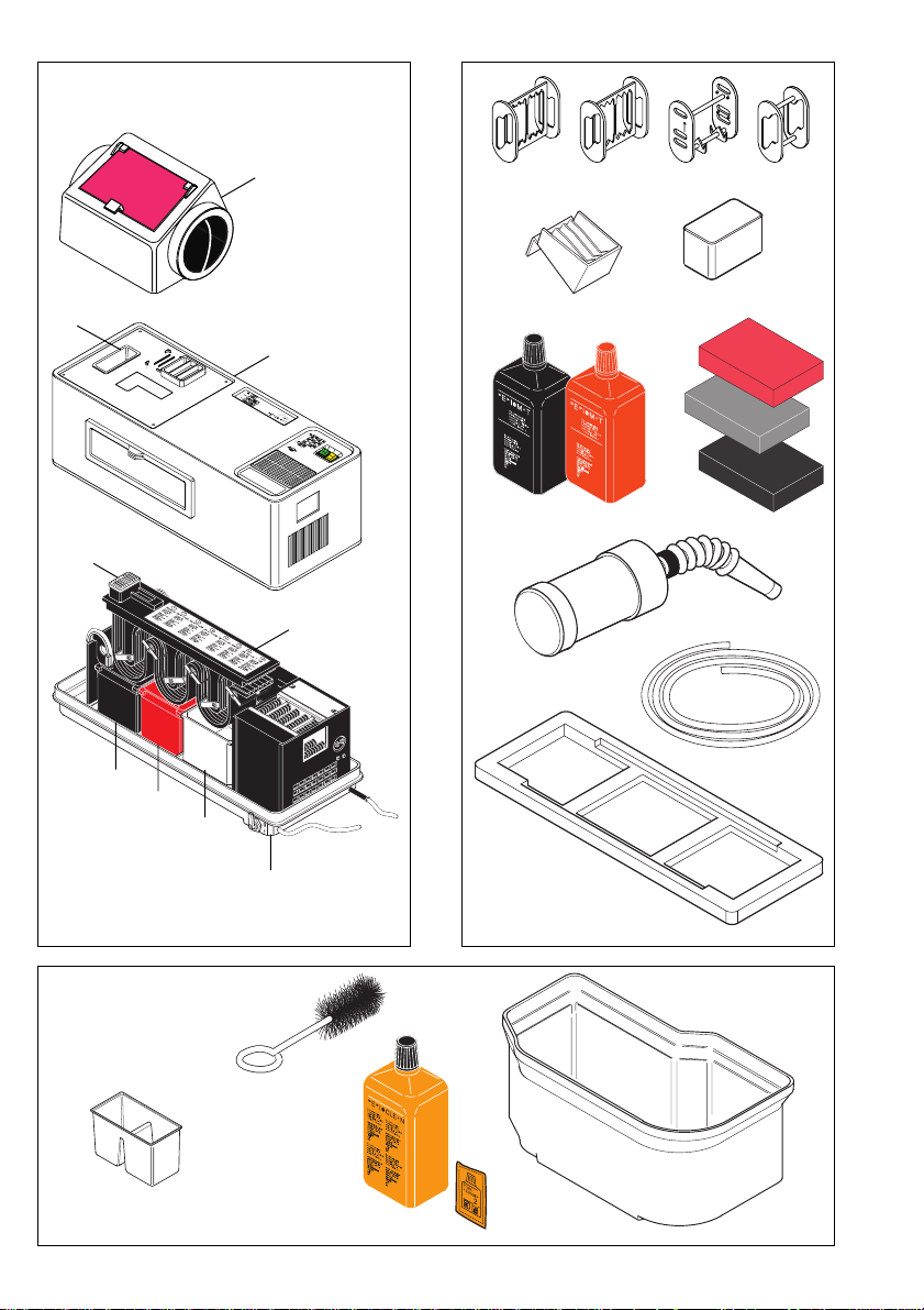
4. DELIVERY CONTENTS
5. TECHNICAL DATA
Fig. 1
(1) Daylight attachment
Model 1307-01, -02, -03 ..... 1307-700-00
(2) Lid ........................................ 1307-981-00
(3) Waste receptacle ................ 1303-000-06
(4) Film feed frame ................... 1303-000-05
(5) Film transport ...................... 1307-300-00
(6) Water bath ........................... 1307-007-00
(7) Fixer bath ............................ 1303-000-09
(8) Developer bath ................... 1303-000-08
(9) Base
Operating instructions D/GB ..9000-600-11/01
4.1 Accessories
Fig. 2
(10) 1 Set of chemicals
Periomat Intra ......................1307-080-00
(11) Adapters for films
3 Pcs. 2x3.5 cm .................. 1303-000-01
2 Pcs. 4x5 and 2.7x5.4 cm .1303-000-02
3 Pcs. 2.4x4 cm .................. 1303-000-18
1 Pcs. 5.7x7.6 cm ............... 1303-000-22
(12) 1 Film collector ....................1303-001-00
(13) 1 Draining rack .................... 1303-000-13
(14) Sponges
2 Pcs. grey .......................... 1330-000-06
1 Pcs. red ............................ 1330-000-05
(15) 1 Lightproof cap
for film entry ....................... 1303-000-14
(16) 1 Water bottle ...................... 1307-001-00
(17) 1 Drain hose ........................ 1307-000-07
4.2 Special accessories
Fig. 3
(18) Cleaning Set
“Perio-Clean” ....................... 1304-070-00
(19) Bath, dual-walled ................ 1303-000-16
Model 1308- 1307-
Voltage (V) 230 230
Frequency(Hz) 50 50
Current (A) 1,8 1,8
Output (W) 400 400
Duty
cycle (%ED) 100
Film run
through
time (min)
50 Hz 5
Developing
temperature (°C) 25
Heating up
time (min/°C) ~7
Heating (V) 24
Fuse (A) T 2,5
Container (l)
Developer 1
Fixer 1
Water 1,25
Weight (kg) 10,2 11,2
Size (HxBxT)
01 01
22x63x25
40x63x25
31
Page 8
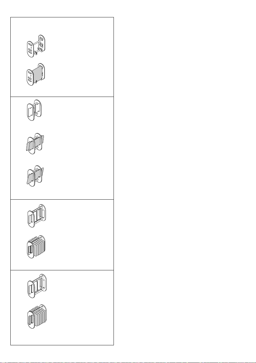
5.1 Recommended film sizes and
adapters
1303-000-22
5,7 x 7,6 cm
1303-000-02
2,7 x 5,4 cm
4 x 5 cm
1303-000-01
WITHOUT Adapter:
• 3 x 4 cm (max. 8 films)
WITH Adapter:
• 5.7 x 7.6 cm (max. 1 film)
• 2.7 x 5.4 cm (max. 2 films)
• 4 x 5 cm (max. 1 film)
• 2 x 3.5 cm (max. 6 films)
• 2.4 x 4 cm (max. 6 films)
The film applications together with the
relevant order numbers can be seen in Fig. 4.
32
2 x 3,5 cm
1303-000-18
2,4 x 4 cm
4
Page 9

6. OPERATING FUNCTIONS
6.1 Indicators
Yellow Indicator: Mains Supply Switch (20)
Pos. O: Periomat + Heating OFF
Pos. l: lit, Periomat + Heating ON
Green Switch: Film-transport Switch (21)
Pos. O: Film transport OFF
Pos. l: Film transport ON, developing starts
20
Green Control Lamp: Heating (30)
Blinks during the warm-up phase from bath
21
temperature of 22° C
5
Lights permanently when chemicals are at
developing temperature
The Periomat is ready for operation when both
mains supply and transport switch indicator
lights are on.
Transport interruption when opening front
panel or cover
For safety reasons, if the front panel is opened
during film development, the transport motor
30
is automatically switched off and the films will
not be transported. The same is true for the
cover (2). This switch-off is controlled by a
31
Reed-switch (30) mounted on the temperature
sensor holder, which is activated by a magnet
(31) mounted on the front panel.
2
6
Disconnect the appliance from the
mains supply before removing the lid.
33
Page 10
MOUNTING
7. INSTALLATION
7.1 Installation - room
• Install the Periomat in a dry, well-ventilated
room.
• The mains supply socket must be so chosen
that the mains supply plug is visible, safe
and easily accessible.
Max. ambient temperature is 25°C.
Do not position the Periomat in
direct sunlight!
Otherwise the films will be exposed
8
5
9
22
8
7
despite the daylight attachment.
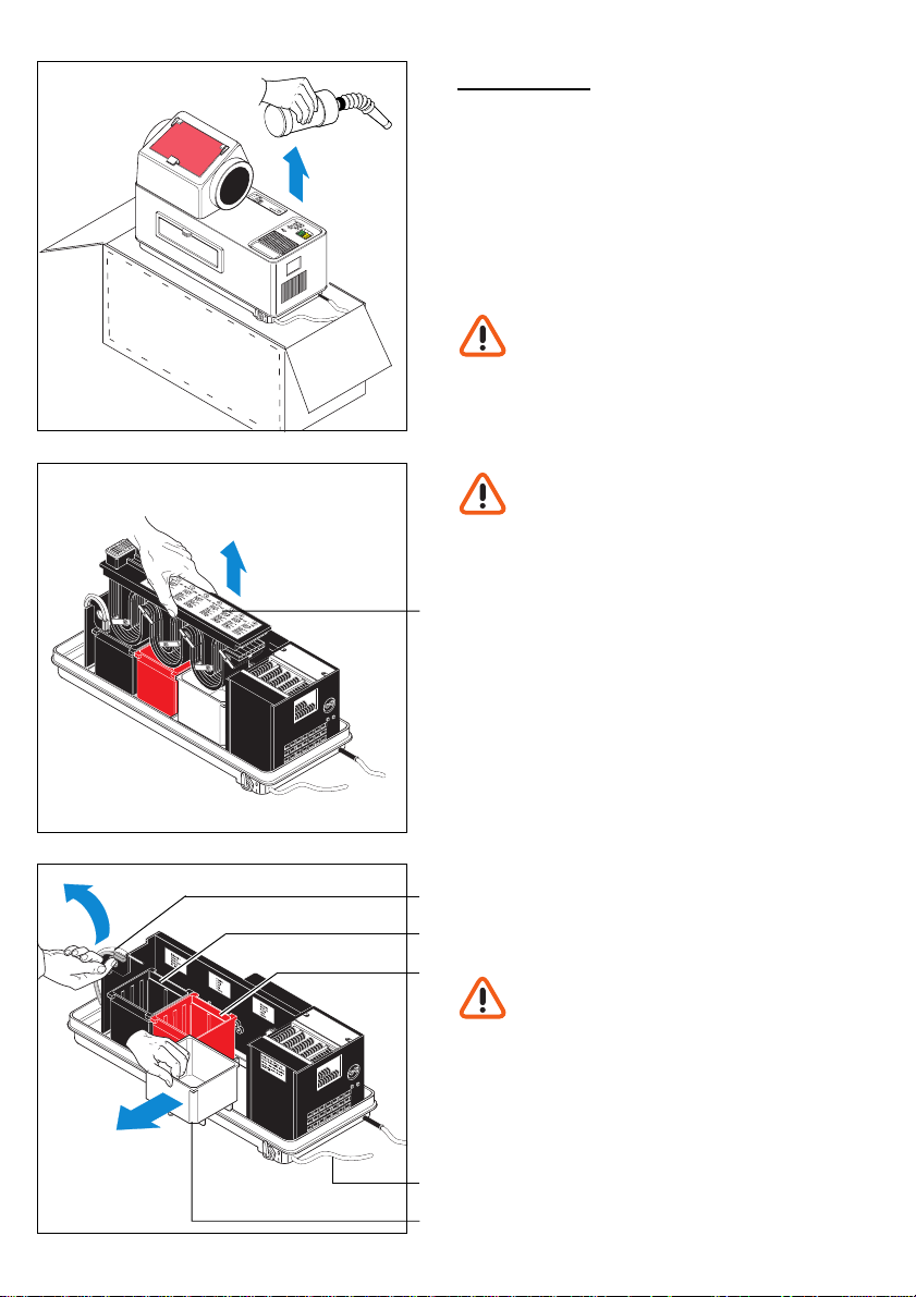
7.2 Installation
Please keep the original packing for
possible return of product. DÜRR
DENTAL accepts no liability for
damage caused during transport,
resulting from faulty or inadequate
packing!
• Lift the Periomat out of its box. Remove the
water bottle and flexible hose from the right
hand packaging. Remove the plastic
packing material.
• Stand the appliance on a stable and level
surface near a mains supply socket.
• Remove lid.
• Remove cardboard box with adapters.
• Remove transport packaging (blue foam
rubber and material in dryer area)!
• Remove sponges from baths.
• Remove the film transport (5) and the three
baths, black “E” (8), red “F” (7) and white
“W” (6), and clean them of any packing
material and dust.
Before removing the “E”-bath,
swing the temperature regulater (22)
to the rear.
34
10
• Fit drainage hose (17).
17
6
Page 11

11
8. COMMISSIONING
4
5
Check that the voltage as given on the
appliance model label corresponds
with the voltage as supplied at the
mains!
If using the appliance for the first time
during winter allow the appliance to
warm to room temperature first,
otherwise there is the risk that
condensation builds up on the
electronic control board causing a
short circuit!
After filling the chemicals do not
move the Periomat as there is the
risk of chemicals mixing!
• Carefully insert the film transport (5).
• Place the numbered film frame (4) onto the
film entry (slot 8 to the front).
• Remove the drainage hose from its holder
and set in collector (min. 5 l) (to collect
water from the water bath). Place this
collector on the floor.
12
13
• Place lid (2) onto appliance (flap to the
front).
• Open and close the front flap until you hear
it click firmly into place.
2
35
Page 12

14
15
• Place the film collector (12) into position.
• Plug appliance into mains socket.
12
• Yellow main switch is set (20) ON (lit).
Both baths “E” and “F” are mounted
on a temperature-regulated heating
plate. If the temperature is below 25°C
during filling, when the yellow main
switch (20) is activated the chemicals
are automatically heated and
maintained at the required
temperature.
Example: Start-up temperature 18°C, warm-
20
up time approx 7 min per °C, ie waiting time is
c. 45 min. until the correct developing
temperature is reached.
21
• The green display (21) begins to blink at a
temperature of 22°C and is fully lit when the
correct developing temperature has been
reached (after ca. 45 min).
Do not develop films until the
control lamp (30) stops blinking!
36
Page 13

9. CIRCUIT DIAGRAM
37
Page 14

9.1 Description
1 Main switch orange
2 Transport switch green
3 Relay
4 Reed contact
5 Transformer
6 Electronics
7 Temperature -Sensor
8 Bath Heating
9 Main plug (earthed)
10 Film dryer ventilator
11 Transport motor
12 Film dryer heating
13 Thermal fuse
14 Power input fuse
15 Controller fuse
16 Distributor 1
17 Distributor 2
18 Distributor power supply
9.2 Cable coloring
gn/ge = green/yellow
rt/sw = red/black
ws/or = white/orange
sw = black
rt = red
br = brown
bl = blue
or = orange
gn = green
38
Page 15
17
18
USE
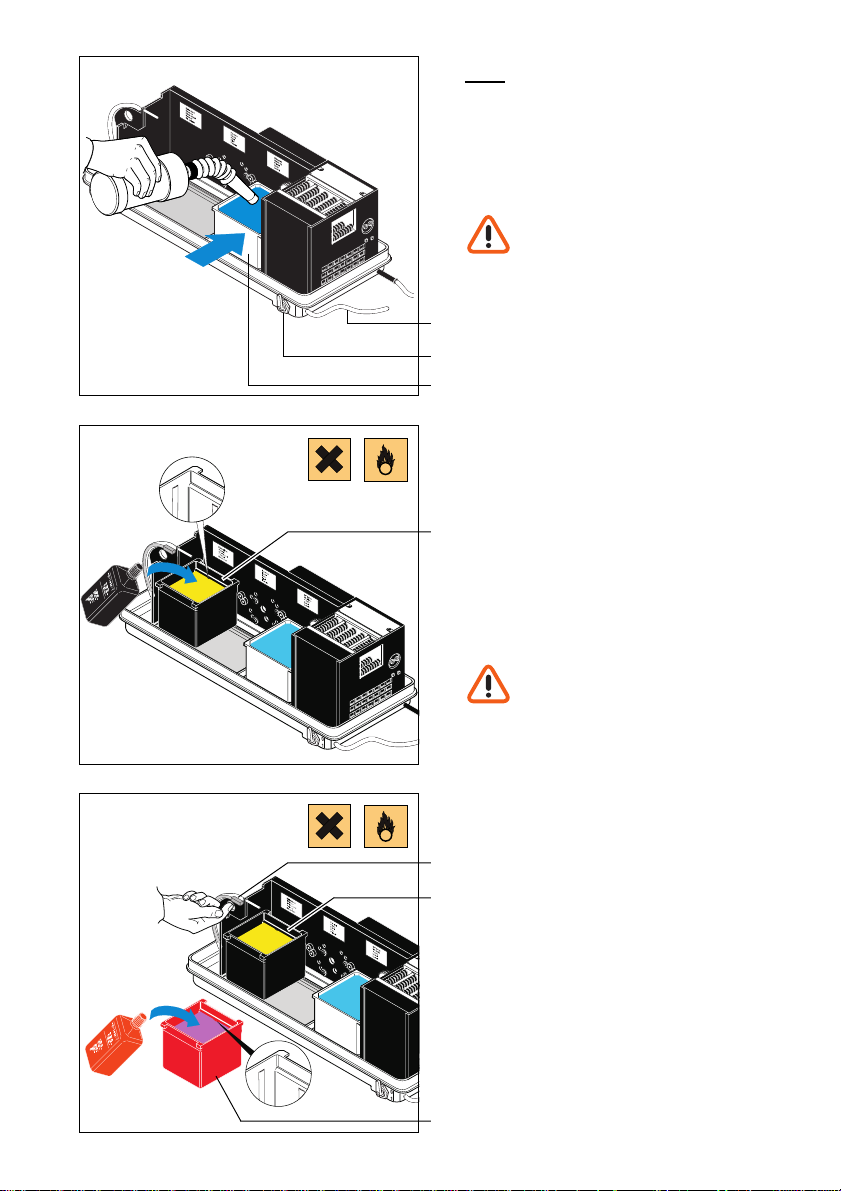
10. FILLING CHEMICALS
In order to produce perfect film results, we
strongly recommend using the specially
developed DÜRR Periomat Intra Chemicals.
Before removing the lid, turn the
yellow power switch OFF and
unplug the appliance.
• Close the water outlet (30).
• Fill the water bottle to the marking (1.25 l)
17
with max. 25°C warm water. Attach hose to
30
bottle.
6
• Pour the complete contents of the water
bottle into the water bath “W” (6).
• Place the black developer bath “E” (8) into
position.
• Pour developer (black bottle) into the black
bath “E” (8).
• Swing the temperature regulater (22)
8
downwards.
• Pour fixer (red bottle) into the red bath “F”
(7) and place bath into position.
• Both baths “F” (7) and “E” (8) should now
be filled with max. 25°C warm water to the
lower marking.
The developer and fixer should be
well stirred, otherwise the results of
developing could vary greatly due
to temperature fluctuations.
19
22
8
7
39
Page 16

20
11. OPERATION
Before inserting films see 5.1
“Recommended film sizes and adapters”.
11.1 Film insertion WITHOUT adapter
• Switch the green transport button (21) ON.
21
• Insert 3 x 4 cm film directly into the
numbered cover (4) of the 8-slot film feeding
frame.
Only 1 film per slot!
21
22
4
15
23
Place root-treatment films in slot 8.
After 2 min. 30 sec. the film should be
removed from slot 8 using tweezers
via the front flap. This film cannot be
used for archival purposes due to
omission of water stage!
• Position lightproof cap (15) in place.
• Push the start lever (23) to the right.
A new film can only be inserted, when
the start lever (23) has returned to its
starting position (after c. 50 seconds).
40
Page 17

23
• After development the 3 x 4 cm films are
deposited in the film collector (12) between
the film separators (24) *.
12
24
• After all films have been deposited in the
film collector, turn the green transport
switch (21) to OFF.
• When the surgery is closed or during longer
breaks (e.g. lunch break) turn the yellow
power switch (20) to OFF.
24
21
41
Page 18

11.2 Film insertion WITH adapter
• Remove the film separators (24) from the
film collector (12).
26
24
12
4
In cases where there is frequent
developing
adapter, we recommend that you
order a second film collector (12).
(Order Nr. 1303-001-00)
• Remove film feed numbered frame (4).
WITH
and WITHOUT an
42
27
• Place film(s) in appropriate adapter:
Occlusal-Film (5.7 x 7.6 cm)
25
• Carefully bend the Occlusal-Film in the
middle.
• Place in the correct adapter (25).
The film must sit firmly in the holder
(26).
26
28
Page 19

29
• Place the adapter (25) in the film feed.
The arrow on the adapter (25) must
point downwards.
25
2 x 3.5 and 2.4 x 4 cm Films
• Place the adapter (27) laterally into the
holder (28) next to the film entry.
27
• Each film (max. 6 films) must be pressed
cross-wise into the slots in the adapter (27)
until they touch the holder.
The films must lie parallel to each other and
must not touch.
28
30
31
• Place the adapter (27) vertically into the film
feed.
27
43
Page 20

32
4 x 5 and 2.7 x 5.4 cm Films
• Each film (max. 2 films) must be placed into
the slots in the adapter (29).
29
• Place the adapter (29) vertically into the film
feed. The edges of the film must not touch
the sides of the film feed shaft.
29
44
33
• Set lightproof cap (15) into place.
• Slide the start lever (23) to the right.
15
23
34
Page 21

35
• After developing, the adapter complete with
film will fall into the film collector (12).
12
• After developing switch the green transport
button (21) to OFF.
• When the surgery is closed or during longer
breaks (e.g. lunch break) turn the yellow
power switch (20) to OFF.
36
37
20
21
11.3 Miscellaneous
• The waste receptacle (3) is provided for the
film packaging, and can be removed for
emptying.
3
45
Page 22

38
12. MAINTENANCE
12.1 Changing the water
Weekly 2 x
and
check level of chemicals!
The drainage hose must be
connected to a water collector (min.
5 l) (to receive water from the water
bath). Place the container on the
floor. On disposal of the waste
water observe all relevant
regulations!
• Turn the yellow mains switch (20) to OFF.
Unplug the appliance.
46
39
40
20
• Open the water outlet (30) and wait until the
container is empty.
30
Page 23

41
42
• Close the water outlet (30).
30
• Fill the water bottle with max. 25°C warm
water to the marking. Replace hose on
bottle.
When changing the water we
recommend the use of an anti-alga
solution.
• Open front flap.
• Pour the contents of the water bottle into
bath “W”.
• Check the levels of developer “E”- and fixer
baths “F” and, if necessary, fill to the
marking (see inside of flap) with max. 25°C
warm water.
The temperature for developer and
fixer is set at 25°C and must not be
exceeded, or the films will appear too
dark.
• Close front flap.
43
• Plug in appliance.
• Switch yellow power switch (20) to ON.
20
47
Page 24
44
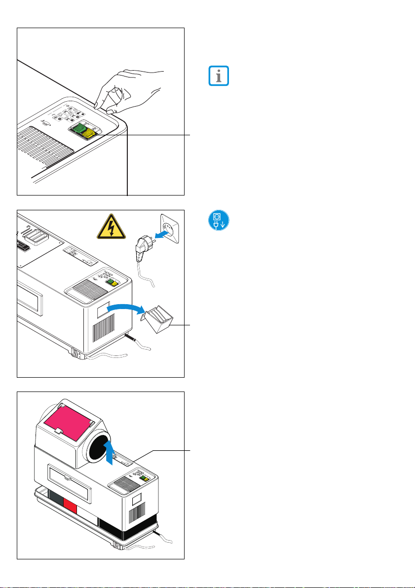
12.2 Changing chemicals
Every 3 weeks
After c. 3 weeks, or after developing c.
350 films of 3 x 4 cm format, the
developer and fixer
must be replenished.
• Turn the yellow mains switch (20) to OFF.
20
Unplug the appliance.
• Remove film collector (12).
are used up and
48
12
45
• Remove lid (2).
2
46
Page 25

47
• Slightly raise the film transport (5), allow the
chemicals to drain off.
• Place the film transport on to the draining
rack.
• Swing temperature regulater (22) to the rear
5
• Rinse the film transport (5) under luke-warm
running water (the film feed must remain
dry).
• Remove any deposits with a brush (included
in the cleaning set “Perio-Clean”).
• Empty of water and chemicals.
In Germany X-ray chemicals are
22
classified as Special Waste and
must be separated and disposed of
separately. Observe all relevant
regulations!
• All 3 baths (6, 7, 8) should be cleaned,
using the appropriate colour-coded sponge,
with warm water and any dirt thoroughly
removed.
• The area around the film feed should be
cleaned using a fluff-free cloth.
• Change the chemicals according to the
instructions in section 9.
48
49
12.3 Chemical cleaning
Every 6 months
• Every 6 months clean the film transport with
8
“chemical cleaner”.
We strongly recommend the use of our
7
chemical cleaning set “Perio-Clean”,
Order.Nr.: 1304-070-00.
Detailed instructions are included in each
cleaning set.
6
49
 Loading...