


580
580
Doppelkettenstich Knopflochautomat,
Einfachkettenstich Schnürlochautomat
Automatic double-chainstitch buttonholer,
Single-chainstitch automat for stitched eyelet
Bedienanleitung / Operating Instructions
Aufstellanleitung / Installation Instructions
Serviceanleitung / Service Instructions
Postfach 17 03 51, D-33703 Bielefeld • Potsdamer Straße 190, D-33719 Bielefeld
Telefon + 49 (0) 5 21 / 9 25-00 • Telefax + 49 (0) 5 21 / 9 25 24 35 • www.duerkopp-adler.com
1
2
3
Ausgabe / Edition: Änderungsindex Teile-Nr./Part.-No.:
02/2008 Rev. index: 02.0 Printed in Federal Republic of Germany 0791 580001

580
Alle Rechte vorbehalten.
Eigentum der Dürkopp Adler AG und urheberrechtlich geschützt. Jede, auch auszugsweise Wiederverwendung
dieser Inhalte ist ohne vorheriges schriftliches Einverständnis der Dürkopp Adler AG verboten.
All rights reserved.
Property of Dürkopp Adler AG and copyrighted. Reproduction or publication of the content in any manner, even in
extracts, without prior written permission of Dürkopp Adler AG, is prohibited.
Copyright ©
Dürkopp Adler AG - 2008
Übersicht Summary
Bedienanleitung
Aufstellanleitung
Serviceanleitung
Bauschaltplan
9890 580001 B
Pneumatik Geraeteplan
9770 580001
Operating Instructions
Installation Instructions
Service Instructions
Interconnection-diagram
9890 580001 B
Pneumatic circuit plan
9770 580001

Foreword
This instruction manual is intended to help the user to become familiar
with the machine and take advantage of its application possibilities in
accordance with the recommendations.
The instruction manual contains important information on how to
operate the machine securely, properly and economically. Observation
of the instructions eliminates danger, reduces costs for repair and
down-times, and increases the reliability and life of the machine.
The instruction manual is intended to complement existing national
accident prevention and environment protection regulations.
The instruction manual must always be available at the machine/sewing
unit.
The instruction manual must be read and applied by any person that is
authorized to work on the machine/sewing unit. This means:
– Operation, including equipping, troubleshooting during the work
cycle, removing of fabric waste,
– Service (maintenance, inspection, repair) and/or
– Transport.
The user also has to assure that only authorized personnel work on the
machine.
The user is obliged to check the machine at least once per shift for
apparent damages and to immediatly report any changes (including the
performance in service), which impair the safety.
The user company must ensure that the machine is only operated in
perfect working order.
Never remove or disable any safety devices.
If safety devices need to be removed for equipping, repairing or
maintaining, the safety devices must be remounted directly after
completion of the maintenance and repair work.
Unauthorized modification of the machine rules out liability of the
manufacturer for damage resulting from this.
Observe all safety and danger recommendations on the machine/unit!
The yellow-and-black striped surfaces designate permanend danger
areas, eg danger of squashing, cutting, shearing or collision.
Besides the recommendations in this instruction manual also observe
the general safety and accident prevention regulations!

General safety instructions
The non-observance of the following safety instructions can cause
bodily injuries or damages to the machine.
1. The machine must only be commissioned in full knowledge of the
instruction book and operated by persons with appropriate training.
2. Before putting into service also read the safety rules and
instructions of the motor supplier.
3. The machine must be used only for the purpose intended. Use of
the machine without the safety devices is not permitted. Observe all
the relevant safety regulations.
4. When gauge parts are exchanged (e.g. needle, presser foot, needle
plate, feed dog and bobbin) when threading, when the workplace is
left, and during service work, the machine must be disconnected
from the mains by switching off the master switch or disconnecting
the mains plug.
5. Daily servicing work must be carried out only by appropriately
trained persons.
6. Repairs, conversion and special maintenance work must only be
carried out by technicians or persons with appropriate training.
7. For service or repair work on pneumatic systems, disconnect the
machine from the compressed air supply system (max. 7-10 bar).
Before disconnecting, reduce the pressure of the maintenance unit.
Exceptions to this are only adjustments and functions checks made
by appropriately trained technicians.
8. Work on the electrical equipment must be carried out only by
electricians or appropriately trained persons.
9. Work on parts and systems under electric current is not permitted,
except as specified in regulations DIN VDE 0105.
10. Conversion or changes to the machine must be authorized by us
and made only in adherence to all safety regulations.
11. For repairs, only replacement parts approved by us must be used.
12. Commissioning of the sewing head is prohibited until such time as
the entire sewing unit is found to comply with EC directives.
13. The line cord should be equipped with a country-specific mains
plug. This work must be carried out by appropriately trained
technicians (see paragraph 8).
It is absolutely necessary to respect the safety
instructions marked by these signs.
Danger of bodily injuries !
Please note also the general safety instructions.

Index Page:
Preface and general safety instructions
Part 1: Operating Instructions Cl. 580
(Edition 02/2008)
1. Product description
1.1 Designated use .................................................5
1.2 Briefdescription.................................................5
1.3 Subclasses....................................................7
1.4 Structure of the product ............................................9
2. Technical data .................................................11
3. Operation
3.1 Needles, threads and gimps .........................................12
3.2 Removingandinsertingtheclampingplates...............................13
3.3 Changing the needle .............................................14
3.4 Threading the upper thread .........................................15
3.5 Threading the looper thread .........................................16
3.6 Threading the gimp thread .........................................17
4. Swivelling the automat up and dow n ..................................18
5. Thread tension
5.1 Upper thread and looper thread tension ..................................19
6. Changing the c utting blocks and knives
6.1 Changing the cutting blocks and knives (580-312000 / 580-321000/ 580-341000) “Multiflex” . . 22
6.1.1 Changing the knives..............................................22
6.1.2 Changing the cutting blocks .........................................23
7. Push buttons .................................................24
8. Setting the f abric stops ...........................................24
9. Switching on - Sw itching off - Threading mode
9.1 Switchingon ..................................................25
9.2 Switchingoff..................................................25
9.3 Threading mode ................................................25
10. Control panel and control unit
10.1 General notes .................................................26
10.2 Control panel .................................................27
1

Index Page:
10.3 Index of the control panel keys .......................................28
10.4 Mainlevelofmenusystem..........................................29
10.4.1 Alteringthevaluesofthemainleveldirectly...............................29
10.4.1.1 Selecting a buttonhole in the main level .................................30
10.4.2 Selecting a s equence or a buttonhole ...................................32
10.4.2.1 Selecting a sequence (Sequence mode) .................................32
10.4.2.2 Selecting a buttonhole (Buttonhole mode) ................................32
10.4.3 Adjustingthethreadtensioninthemainlevel ..............................33
10.4.4 Adjusting the c utting length in the main level ...............................33
10.4.5 Cuttingmode..................................................34
10.4.6 The piece c ounter ...............................................34
10.4.7 Automatic or manual operation (can only be set in sequence mode) .................35
10.5 Buttonhole programming ...........................................36
10.5.1 Selectionofamenuitem...........................................36
10.5.2 Editingofavalue ...............................................36
10.5.3 Programming a buttonhole .........................................37
10.5.4 Listofmenuandsubmenuitems......................................38
10.6 Sequences ...................................................41
10.6.1 General .....................................................41
10.6.2 Switching on / off the sequence mode ...................................41
10.6.3 Programming a sequence ..........................................42
10.6.4 Inserting a buttonhole at the end of a sequence .............................43
10.6.5 Deleting a buttonhole at the end of a sequence .............................43
10.6.6 Inserting a buttonhole in within a sequence ...............................44
10.7 Sewing .....................................................45
11. Information messages
11.1 Needle not in basic position .........................................47
11.2 Threading mode ................................................47
11.3 Threadbreakage................................................47
11.4 Pressuremonitor ...............................................47
11.5 Invalidcuttingconfiguration.........................................47
11.6 Abnormal threading mode ..........................................48
12. Error messages................................................48
13. Maintenance
13.1 Cleaning .....................................................49
13.2 Lubricating ...................................................50
13.3 Control......................................................51

1. Product description
1.1 Designated Use
The DÜRKOPP ADLER 580 is a sewing automat designed for the sewing
of buttonholes in light to medium-weight material.
Such material, which is generally made of textile or synthetic fibres, is
used in the clothing industry. Furthermore, this sewing automat can
possibly also sew so-called technical s eams. However, in this case the
user has to evaluate the possible risks (preferably in cooperation with
DÜRKOPP ADLER) since such applications are rather rare and the
variety of possibilities is vast. According to the result of this evaluation
suitable safety measures are to be taken. Generally only dry fabrics must
be processed with this machine. The material must not be thicker than
8mmwhen compressed by the lowered upper fabric clamps.
The material may not contain any hard objects. The person operating the
automat has to wear finger and eye protection. The sewing automat
must be installed and operated in dry and well-kept rooms only. If it is
operated in other rooms, that are not dry and well-kept further measures
which have to be agreed upon (see EN 60204-31:1999) can become
necessary. We as manufacturers of industrial sewing automats take it for
granted that at least semi-skilled operators are working with our products
so that we can assume that all usual operations and their risks are known
to them.
1.2 Brief description
The DÜRKOPP ADLER 580 is a double-chainstitch buttonhole
automat or a single-chainstitch automat for stitched eyelets with CNC
step motor technology for the material feed and the rotation of the
sewing mechanism.
The buttonhole automat works with two chainstitch loopers, the left one
being thread-guiding. For sewing of buttonholes with or without eye,
with taper tack, round tack, cross tack or without bartacks.
As eyelet automat it works with two chain stitch-blind-loopers for the
sewing of single stitched eyelets.
The automat is equipped with a upper thread trimmer and an
electronically regulated upper thread tension.
Depending on the subclass, the 580 comes with different types of
thread trimmer systems.
Technical features
The automat is driven by a positioning drive integrated in the machine
arm.
The drive for the motion of the axis X, Y and Z is effected by one step
motor for each axis. These drives are controlled via an electronic
control in c onjunction with various pneumatic machine functions.
This drive and control system offers the following advantages:
–
Variable sewing speed according to the sewing parameters
(e.g. upper thread, looper thread, material, seam width)
up to a maximum of 2200 stitches/min.
–
Quiet running (no mechanical switching on and off).
Additional noise reduction by optimized needle bar and looper
drive.
–
The use of step motors allows a very variable field of application.
No use of control cams.
–
The control panel with membrane keyboard that is able to display
graphics is fitted on the right side of the sewing head within easy
reach of the operator.
5
1

–
The following functions are operated via manual switches:
- Closing and opening the clamp
- Activating the sewing operation
- Quick stop with needle position “up”
–
Pneumatic cutting of the buttonhole.
–
Automatic adaptation of the cutting power for the buttonhole knife
dependent on the programmed buttonhole length.
–
Due to the vertically working cutting system support no follow-up
work required in case of different cutting block heights.
–
Vacuum extraction of the eyelet cut wastes
–
Central oil wick lubrication from two oil reservoirs.
–
Switch at the head cover for moving to the ideal position for
threading in.
–
Electronically controlled upper thread tension.
–
In case of upper thread breakage the upper thread monitor
interrupts the sewing cycle, the fabric clamps remain closed and
hold the workpiece which can be removed at the touch of a button.
–
Covered, smooth design. The swivelling up of the automat is
supported by a gas-pressurized spring which also helps that the
machine head is swivelled back slowly.
–
The special design of the machine arm allows for a vertical
positioning of the fabric by using a different cloth detention device
(additional equipment).
Control
–
Counter indicating the number of buttonholes sewn on the display.
–
You can define up to 50 different buttonholes. Up to 25 buttonhole
sequences with up to 5 programmed buttonholes can be
memorized. One sequence may contain up to 9 different
buttonholes, every buttonhole can be 9 times repeated
consecutively within the sequence.
–
Integrated test and monitoring system ”Multitest”. This system
allows not only for a monitoring of the s ewing process but also for
a quick testing of the input and output elements as well as of the
motor functions without additional measuring instruments.
–
By means of a setting provision on the display it is made possible
that the fabric support plate moves to the initial position of the next
buttonhole after releasing the workpiece. This allows for a better
view when positioning the fabric.
–
According to the buttonhole type the following parameters can be
set at the control:
- with or without eye
-tacktype
(with taper tack, round tack, cross tack or no tack)
- max. speed: 2200 min
-1
- buttonhole length
- cutting before or after sewing
- no cutting
- stitch distance
-formofeye
- electronic setting of the stitch row gauge (-1,0 mm to +0,5 mm)
- number of stitches in the eye
6

1.3 Subclasses
580-112000 With short trimmer for the upper and the looper thread.
The looper thread trimmer is integrated into the throat
platesothatthetreadcanbetrimmedveryclosetothe
fabric. To be used for buttonholes with taper tack, cross
tack, with or without eye.
In conjunction with the corresponding sewing
equipment, it can be also be used for double-stitched
eyelets.
An electropneumatic upper thread catcher is part of the
standard equipment.
The cut length is max. 38 mm, depending on the sewing
equipment.
Without a lower gimp.
580-121000 With short trimmer for the upper thread and long thread
trimmer (approx. 3 0 mm thread length) for the looper
thread and the gimp.
Looper thread and gimp can thus be pulled tight or
pulled through for the subsequent sewing of a lockstitch
tack.
After the sewing of a cross tack they are trimmed short
manually.
To be used for buttonholes with or without eye, for
cutting before o r after sewing, with taper, round and
cross tacks or no tacks.
For cut lenghts of up to 38 mm.
An electropneumatic thread catcher and a lower gimp
guide are part of the standard equipment. It catches the
upper thread right after the trimming, holds it and lays it
when sewing the next buttonhole into the right
buttonhole seam. This guarantees:
- a safe seam beginning also with light and loose fabric .
- tightly pulled stitches from beginning of sewing.
- a proper buttonhole rearside, no more cleaning out.
580-141000 With short trimmer for upper and looper thread and lower
gimp.
To be used for buttonholes with or without eye, for cutting
before or after sewing, with taper, round and cross tacks or
no tack.
With these automats buttonhole length, cutting length and
taper tack length can be adjusted after insertion of
corresponding clamping plates.
Three set of clamping plates are designated:
L1 for sewing lengths of 12 - 24 mm
L2 for sewing lengths of 16 - 28 mm
L3 for sewing lengths of 24 - 36 mm
Different taper tack lengths are possible within these
groups.
An electropneumatic thread catcher and a lower gimp
guide are part of the standard equipment.
580-151000 With short trimmer for the upper thread.
Universal machine for cut lenghts of 10 - 50 mm and
buttonholes in fabric of different qualities and thickness,
depending on the sewing equipment optional with or
without lower gimp.
In conjunction with the corresponding sewing equipment
also to be used for single-chain stitch eyelets.
To be used for buttonholes with or without eye, for
cutting before o r after sewing, with taper, round and
cross tacks or no tack.
7
1

580-312000 With short trimmer for upper and looper thread.
The looper thread trimmer is integrated into the throat
plate, so that the thread can be trimmed very close to
the fabric.
Equipped as standard with an electropneumatic upper
thread catcher and the buttonhole cutting system
“Multiflex”. The “ Multiflex” system allows the cutting of
various buttonhole length, buttonhole shapes and round
eyelets without changing the cutting tools.
Equipped as standard with two cutting blocks and three
knives.
Cutting length from 16 mm up to 36 mm or from 9 mm
up to 31 mm can be set, depending on the cutting block.
Special cuttings like only the buttonhole eye, buttonhole
seam are possible with the standard equipment.
Without a lower gimp.
580-321000 With short trimmer for the upper thread and long thread
trimmer for the looper thread and the gimp.
Looper thread and gimp can thus be pulled tight or
pulled through for the subsequent sewing of a lockstitch
tack. After the sewing of a cross tack they are trimmed
short manually.
Equipped as standard with an electropneumatic upper
thread catcher and the buttonhole cutting system
“Multiflex”. The “ Multiflex” system allows the cutting of
various buttonhole length, buttonhole shapes and round
eyelets without changing the cutting tools.
Equipped as standard with two cutting blocks and three
knives.
Cutting length from 16 mm up to 36 mm or from 9 mm
up to 31 mm can be set, depending on the cutting block.
Special cuttings like only the buttonhole eye, buttonhole
seam are possible with the standard equipment.
With a lower gimp guide and a gimp advancing device.
580-341000 With short trimmer for upper and looper thread and lower
gimp.
To be used for buttonholes with or without eye, for
cutting before o r after sewing, with taper, round and
cross tacks or no tack.
The standard equipment includes an electropneumatic
thread catcher.
With these automats buttonhole length, cutting length
and taper tack length can be adjusted after insertion of
corresponding clamping plates.
Three set of clamping plates are designated:
L1 for sewing lengths of 12 - 24 mm
L2 for sewing lengths of 16 - 28 mm
L3 for sewing lengths of 24 - 36 mm
Different taper tack lengths are possible within these
groups.
Equipped as standard with a lower gimp guide and the
buttonhole cutting system “Multiflex”. The “Multiflex”
system allows the cutting of various buttonhole length,
buttonhole shapes and round eyelets without changing
the cutting tools. Equipped as standard with two knives,
two eyelet k nives (Ø 3 mm, Ø 4 mm) and the
supplementary kit for the operating mode “simple cut”.
Cutting length from 16 mm up to 36 mm can be set,
depending on the sewing equipment.
8

1.4 Structure of product
Subclasses
Equipment Material number
Sewing automat 0580 990001 X
0580 990002 X
0580 990004 X
0580 990005 X
0580 990021 X
0580 990022 X
0580 990024 X
Accessories 0791 580501 X X X XXXX
Optional equipment:
Pneumatic connection set 0797 003031 O O O O O O O
Integral sewing lamp (LED) 0580 100344 X X X XXXX
Foot switch 9880 580002 O O O OOOO
Upper gimp guide 0580 590804 O
Upper thread catcher 0580 590154 X X X X X X
Upper thread catcher 0580 590144 O
Fabric deflector for back trousers 0580 590574 O O O O
Support table for operating while standing 0580 590504 O O O O O
Positioning aids
Spacer for the distance buttonhole to buttonhole (R+L) 0580 590294 O O O O O
Spacer (R+L) for the distance buttonhole
to fabric edge 0580 590404 X X X XXXX
Centering device 0580 591224 DÑÑ
Laser marking lamp 0580 590564 O O O OOOO
Slide-on table for vertical positioning 0580 590604 O O O O O
Kit for vertical positioning 0580 590554 O
(left and right clamping plate)
Kit for vertical positioning 0580 590384 O O
(left and right clamping plate)
Kit for vertical positioning 0580 590374 O
(left and right clamping plate)
Kit light barrier for automatic 0580 591524 O O O O O
buttonhole sequence
X = Standard equipment
O = Optional equipment
D = Can only be ordered in connection with the sewing equipment E1151
Ñ = Can only be ordered in connection with the length package L1 or L2
9
1
580-112000
580-312000
580-121000
580-321000
580-141000
580-151000
580-341000

Subclasses
Equipment Material number
Stands
MG58-13 (regular installation) MG58 400104 O O O OOOO
Stand with fastening parts and table top 1060 x 750
incl. maintenance unit and rollers
MG58-13 (regular installation of a narrow stand) MG58 400124 O O O OOOO
Stand with fastening parts and table top 620 x 750
incl. maintenance unit and rollers
MG58-13 (vertical positioning, narrow stand) MG58 400114 O O O
Stand with fastening parts and table top 1060 x 600
incl. maintenance unit and rollers
X = Standard equipment
O = Optional equipment
10
580-112000
580-312000
580-121000
580-321000
580-141000
580-151000
580-341000

2. Technical data
Machine head: Class 580
Type of sewing stitch: Double-chain stitch
Number of needles: 1
Needle system: 558 / 579
Attention!
When changing over from one needle system to the other the distance
between looper and needle and the adjustment of the needle
protection have to be checked imperatively (see service instructions).
Max. needle size: Nm 80-120 (558) / Nm 90-125 (579)
Upper thread size: max. Nm 50
Looper thread size: max. Nm 30
Max. speed: 2200 min
-1
Stitch length: 0,5-2mm
Max. sewing length: 38 mm (subclass 580-11200)
(depend. on sewing equip.) 38 mm (subclass 580-12100)
38 mm (subclass 580-14100)
50 mm (subclass 580-15100)
38 mm (subclass 580-31200)
38 mm (subclass 580-32100)
36 mm (subclass 580-34100)
Max. cutting length: 38 mm (subclass 580-11200)
(depend. on sewing equip.) 38 mm (subclass 580-12100)
32 mm (subclass 580-14100)
50 mm (subclass 580-15100)
36 mm (subclass 580-31200)
36 mm (subclass 580-32100)
36 mm (subclass 580-34100)
Operating pressure: 6 bar ± 0,5 bar
Air consumption: approx. 3 NL per working cycle
Rated load: 320 VA
Rated voltage: 1 x 190-240 V, 50/60 Hz
Dimensions Machine head:
550 x 370 x 580 (L x W x H)
Table top (regular installation):
1060 x 750 x 1150 mm (L x W x H)
Table top (narrow stand):
620 x 850 x 1150 mm (L x W x H)
Working height: 730-900 mm
(upper edge of the table top)
upper edge of the machine table:
830-1000 mm
Weight with stand: approx. 160 kg
Weight of head: approx. 100 kg
Weight of control: approx. 12 kg
11
1

3. Operation
3.1 Needles, threads and gimps
Needles
Needle system: 558 / 579
Needle sizes: Nm 80-120 (558) / Nm 90-125 (579)
according to the type of sewing thread, fabric and
sewing equipment (E-No.).
Attention!
When changing over from one needle system to the other the distance
between looper and needle and the adjustment of the needle
protection have to be checked imperatively (see service instructions).
Threads
The look of the buttonhole is essentially influenced by the sewing
thread used.
Threads of synthetic fibre or silk threads can be used as needle and
looper threads.
The look of the buttonhole is essentially influenced by
–
the thread used.
–
the use of different upper and looper thread sizes.
Gimps
The gimp is meant to stabilize the buttonhole and to give it a relief-type
appearance at the same time.
It should have the following features:
–
not too thick, but supple and tight
–
even thickness
The threads mentioned in the following table are recommendations
only. Depending on the sewing equipment (E-No.) and the material
also other threads and thread sizes may be required.
Subclass Type and size of upper Type and size of looper Type and size of lower
thread thread gimp
580-112000 Polyester fibre thread, Polyester fibre thread, not necessary
schappe-silk spun schappe-silk spun
580-312000 70/3 70/3
80/3 70/3
580-141000 Poly-Poly 80/2 Poly-Poly 80/2 Poly-Schappe 15/3
580-151000
580-321000
580-341000
12
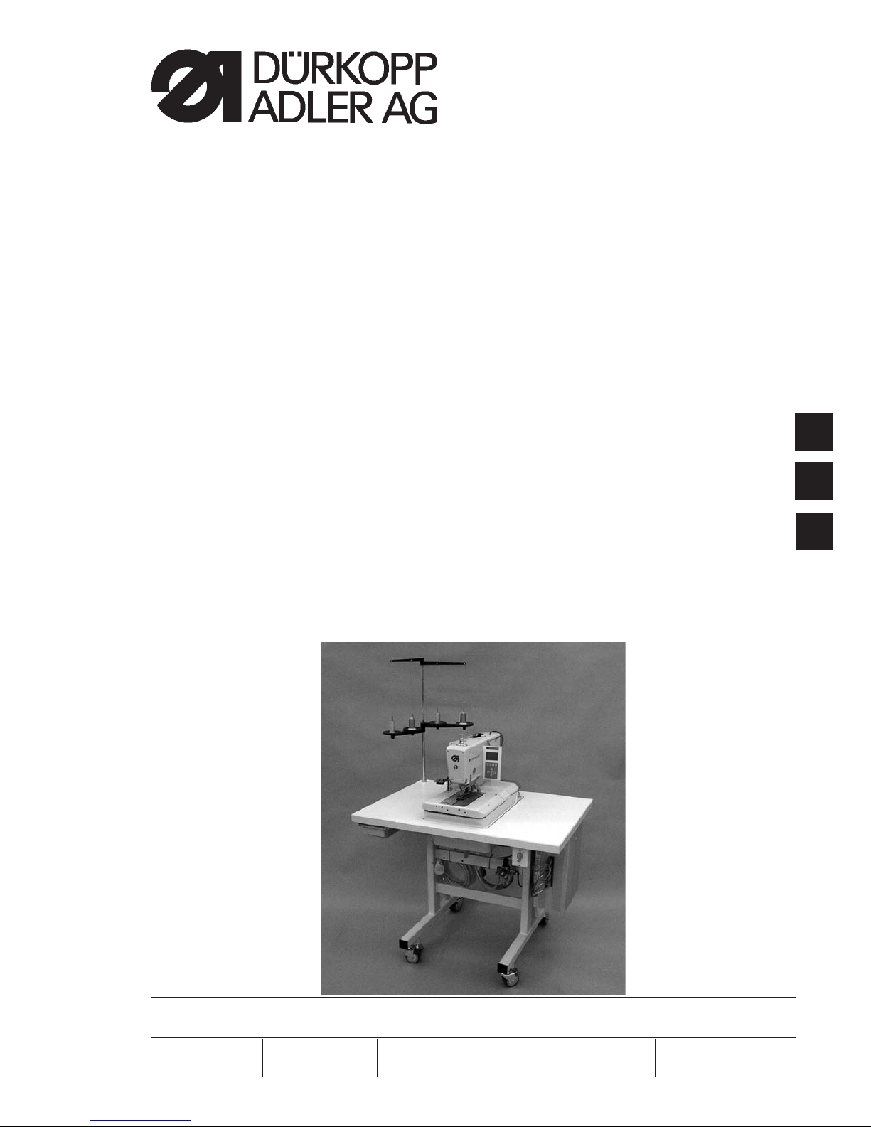
3.2 Removing and inserting the clamping plates
Caution: Danger of injury !
The removing and inserting of the clamping plates 1 has to be done
with the s ewing automat switched off o r in the position “Threading
mode” (see chapter “Threading mode”).
Removing the clamping plate
–
Lift the right clamping plate 1 slightly at the rear and pull it to the
back. Then remove the clamping plate to the right side.
–
Lift the left c lamping plate 1 slightly at the rear and pull it to the
back. Then remove the clamping plate to the left side.
Inserting the clamping plates
–
Push the clamping plate into its front seat.
–
Then snap it at the rear into the pin 3.
Important note!
Wrongly inserted clamping plates can lead to damage or injuries
13
1
1
3
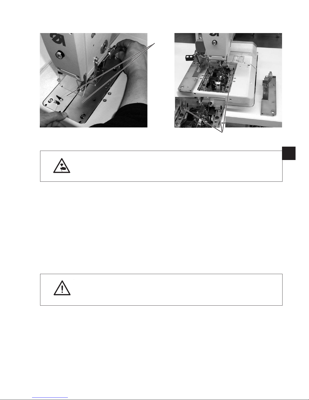
3.3 Changing the needle
Caution: Danger of injury !
The needle has to be changed with the sewing automat switched off or
in the position “Threading mode” (see chapter “Threading mode”).
–
Loosen the screw 1 (Allen key in the accessories).
–
Pull the needle 2 out of the needle bar.
–
Push the new needle as far as it will go into the hole of the needle
bar.
–
Align the needle 2 so that the hollow groove points to the front and
the flat side 3 at the needle butt to the left (towards the fastening
screw 1). Only the needle system 579 has this flat side 3 !
When using needle system 558 align the needle 2 so that the
hollow groove points to the front.
–
Tighten screw 1.
14
1
2
3
 Loading...