

Page 1
Page 2

Teileliste und Klammersaetze
Parts List and Clamp sets
511
Inhaltsverzeichnis Tafel / Table Contents
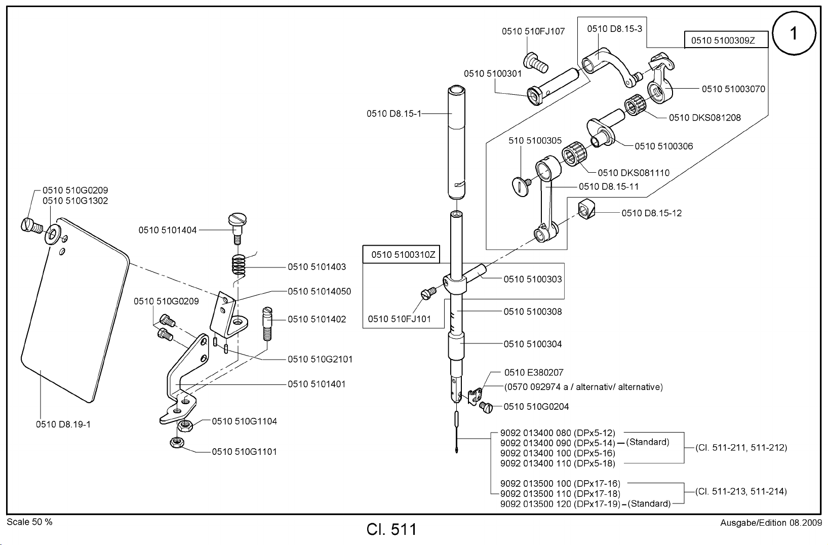
Nadelstange 1 Needle bar
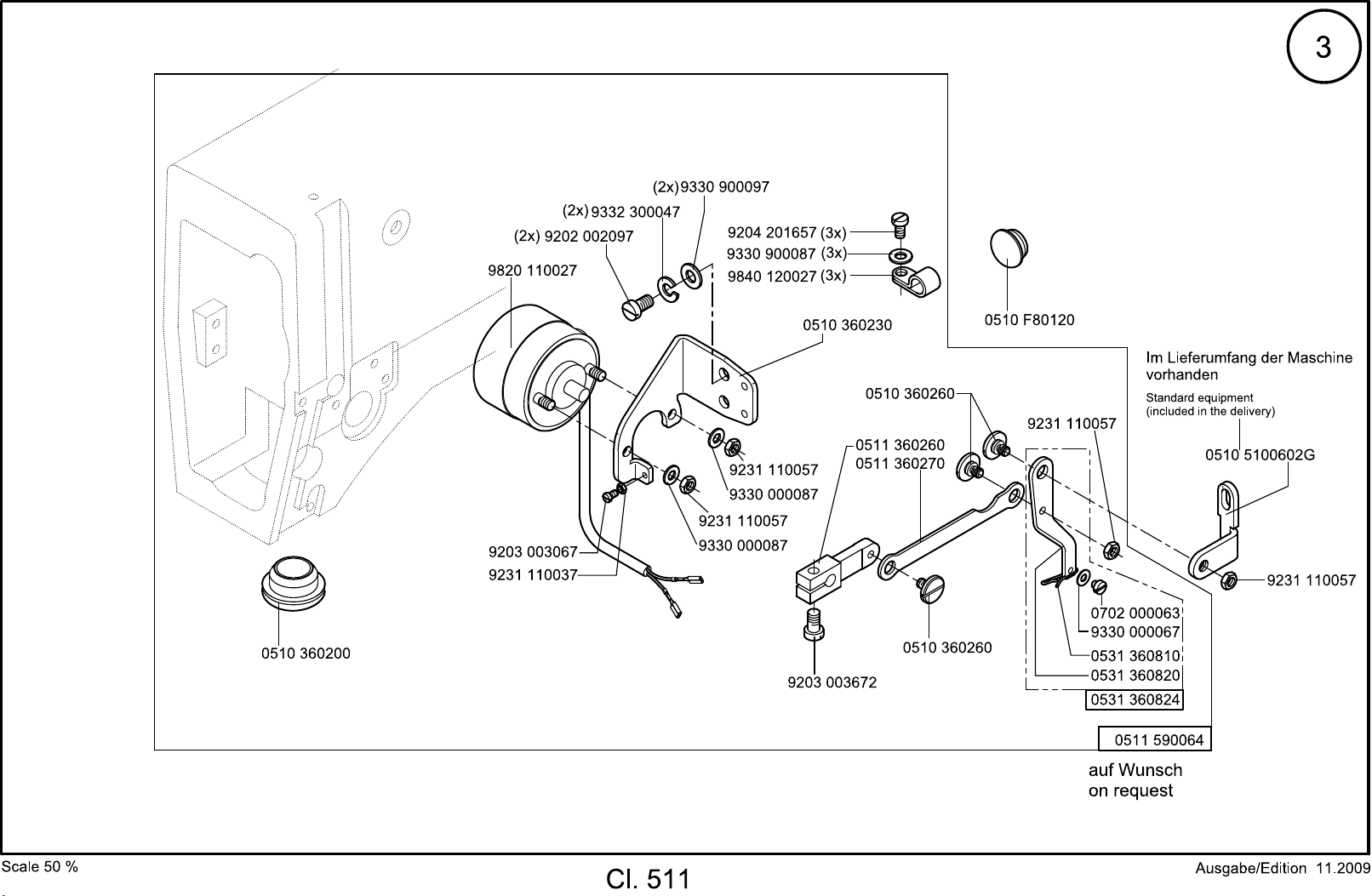
Fadenwischer 3 Thread wiper
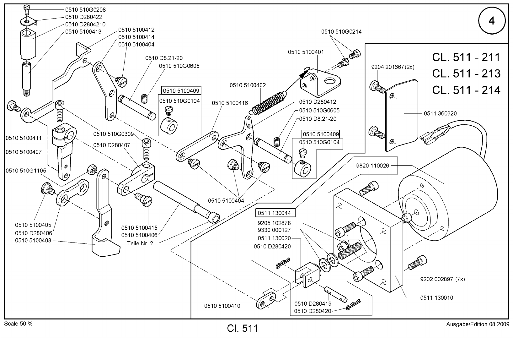
Klammerlueftung 4, 5 Clamp lifting
Greifertreiber 6 Hook driver
Fadenspannung 7 Thread tension
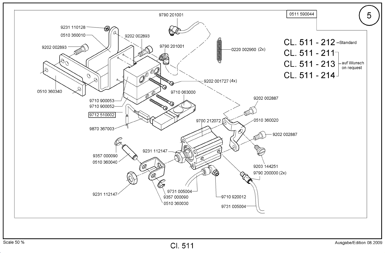
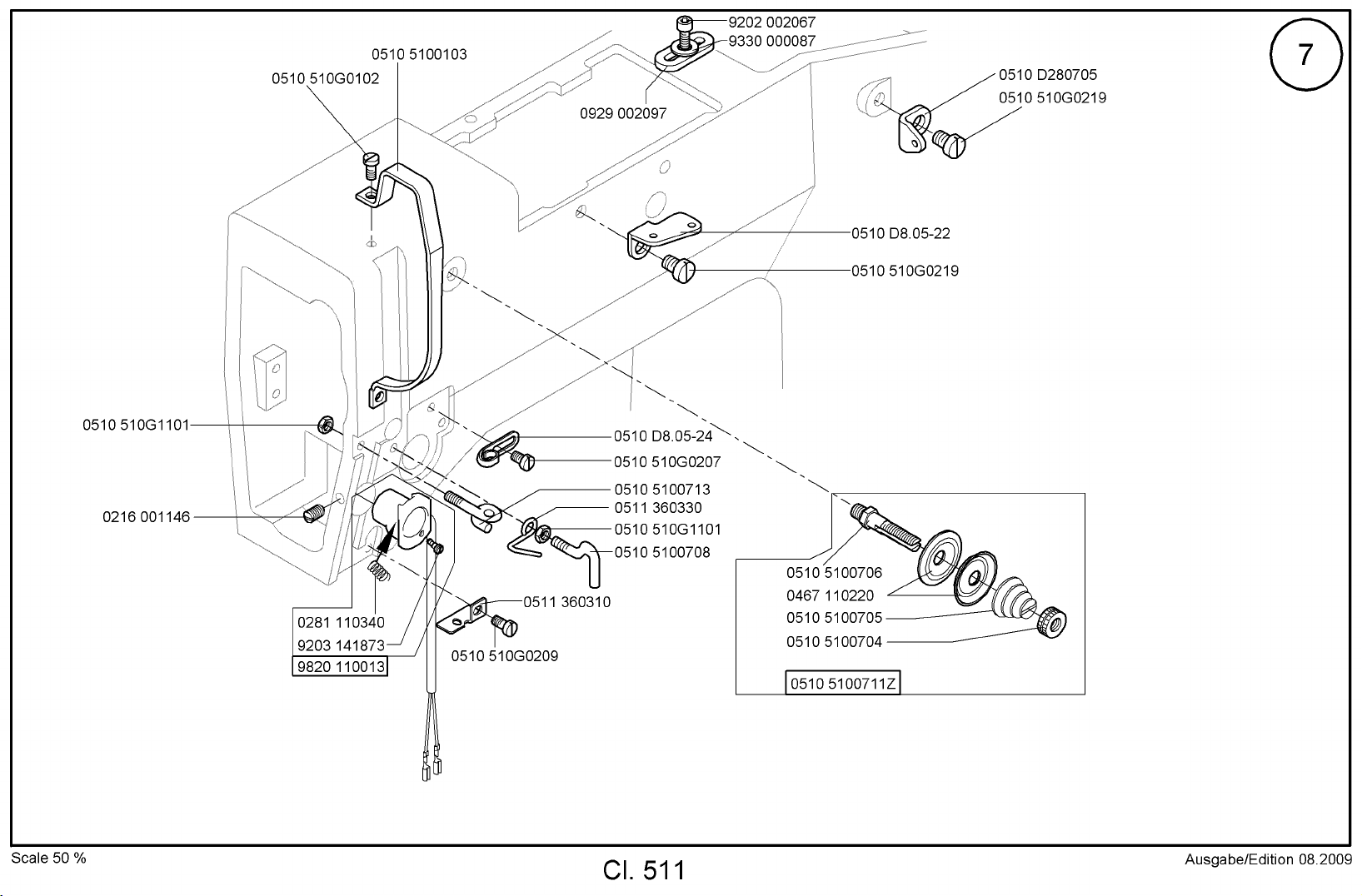
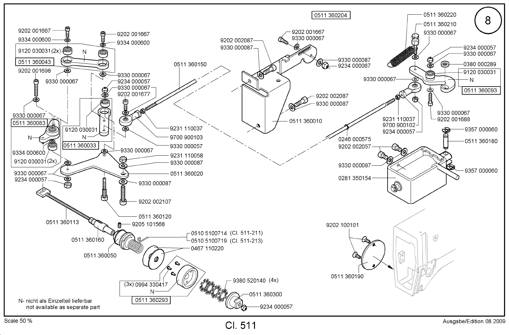
Fadenabschneider 8 - 10 Thread trimmer
Transporteinrichtung 11 Feed drive
Kontraktionsklammer 12 Contraction clamp
Transporteinrichtung 13 Feed drive
(Schrittmotore) (Step motors)
Rahmen und Abdeckung 15 Frame and covering
Schmierung 16 Lubrication
Elektroteile 18 Electronics
Fadenwischer elektrisch 19 Electric thread wiper
Bedienfeld 20 Control panel
Lasermarkierungsleuchte 21 Laser marking lights
Handtaster 22 Push-buttons
Klammerfussabsenkung 23 Lowering device for the clamp
Wartungseinheit 24 Maintenance unit
Zusatzausstattung Optional equipment
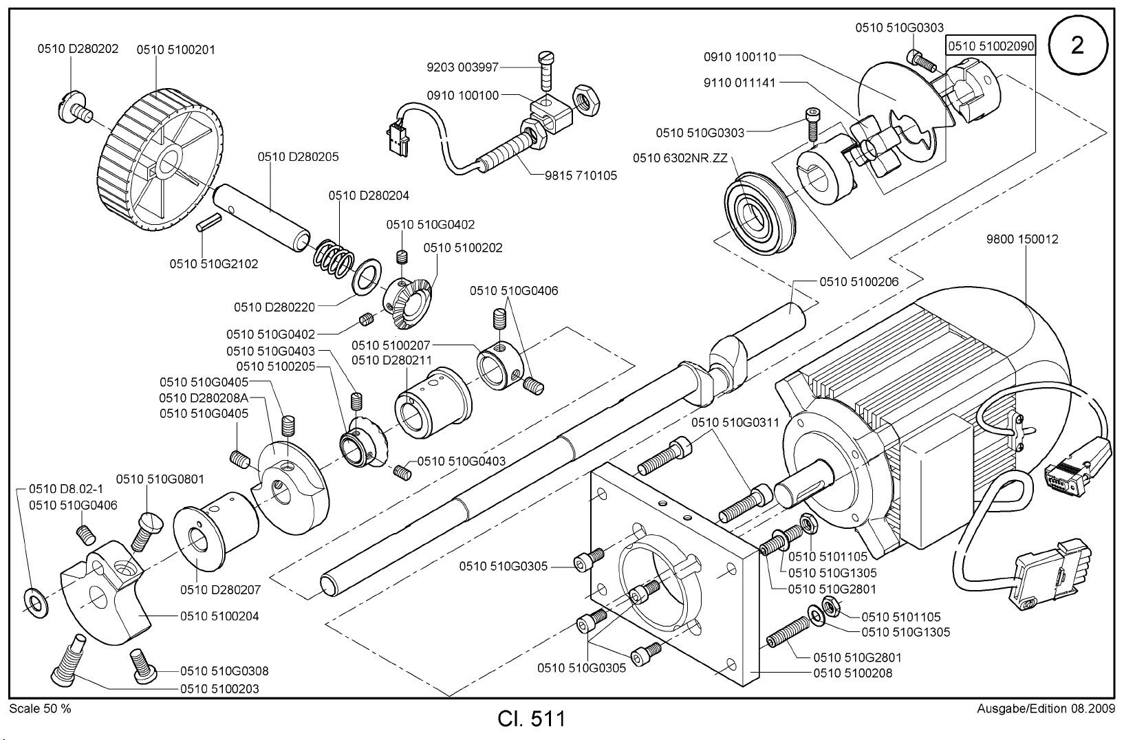
Armwelle 2 Arm shaft
(Klammer) (Clamp)
Spuler 14 Winder
Gestell 17 Stand
Beipack / 25 Accessories /
Klammersaetze Clamp sets
Plaene Plans
Alle Rechte vorbehalten.
Eigentum der Dürkopp Adler AG und urheberrechtlich geschützt. Jede, auch auszugsweise
Wiederverwendung dieser Inhalte ist ohne vorheriges schriftliches Einverständnis der Dürkopp Adler AG
verboten.
All rights reserved.
Property of Dürkopp Adler AG and copyrighted. Reproduction or publication of the content in any
manner, even in extracts, without prior written permission of Dürkopp Adler AG, is prohibited.
Copyright ©
Dürkopp Adler AG - 2010
Page 3
Dürkopp Adler AG
1 2 3 4
Verschleißteile der Klasse 511
Wearing parts of class 511
Part-Nr.: 0791 511800
Edition: 10/2008
Seite 1 / 3
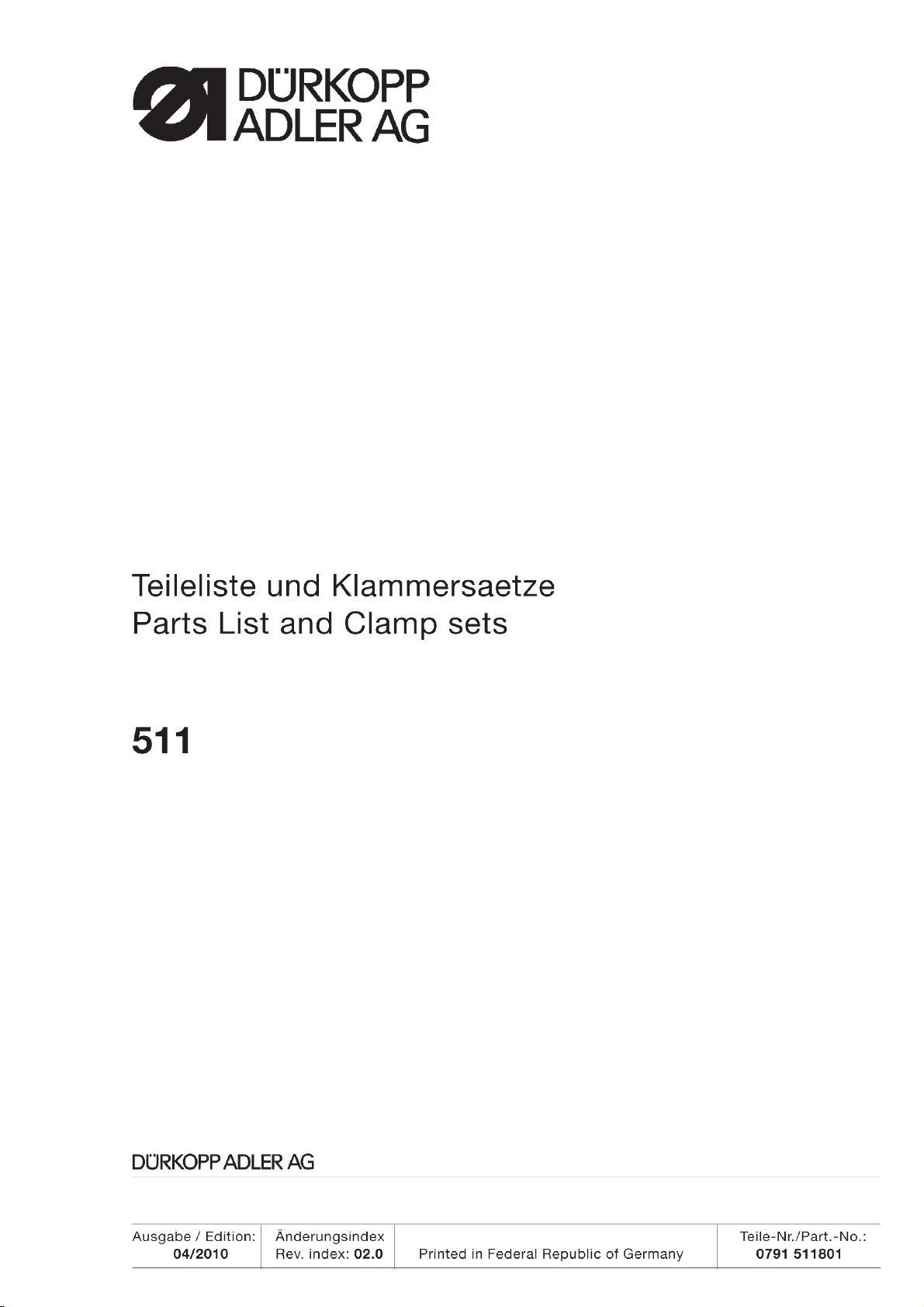
0510 D280515 0570 001015 Ersatz
replacement
Spule, normal
Bobbin
0510 150050 (511-214)
0510 D280511
Spulenkapsel, normal
Bobbin case
0510 150040
(511-214)
0510 150070
Greifer, normal
Hook
0510 150030
(511-214)
0510 5100517Z
Treiber, normal
Driver
0510 150020
(511-214)
5 6 7 8
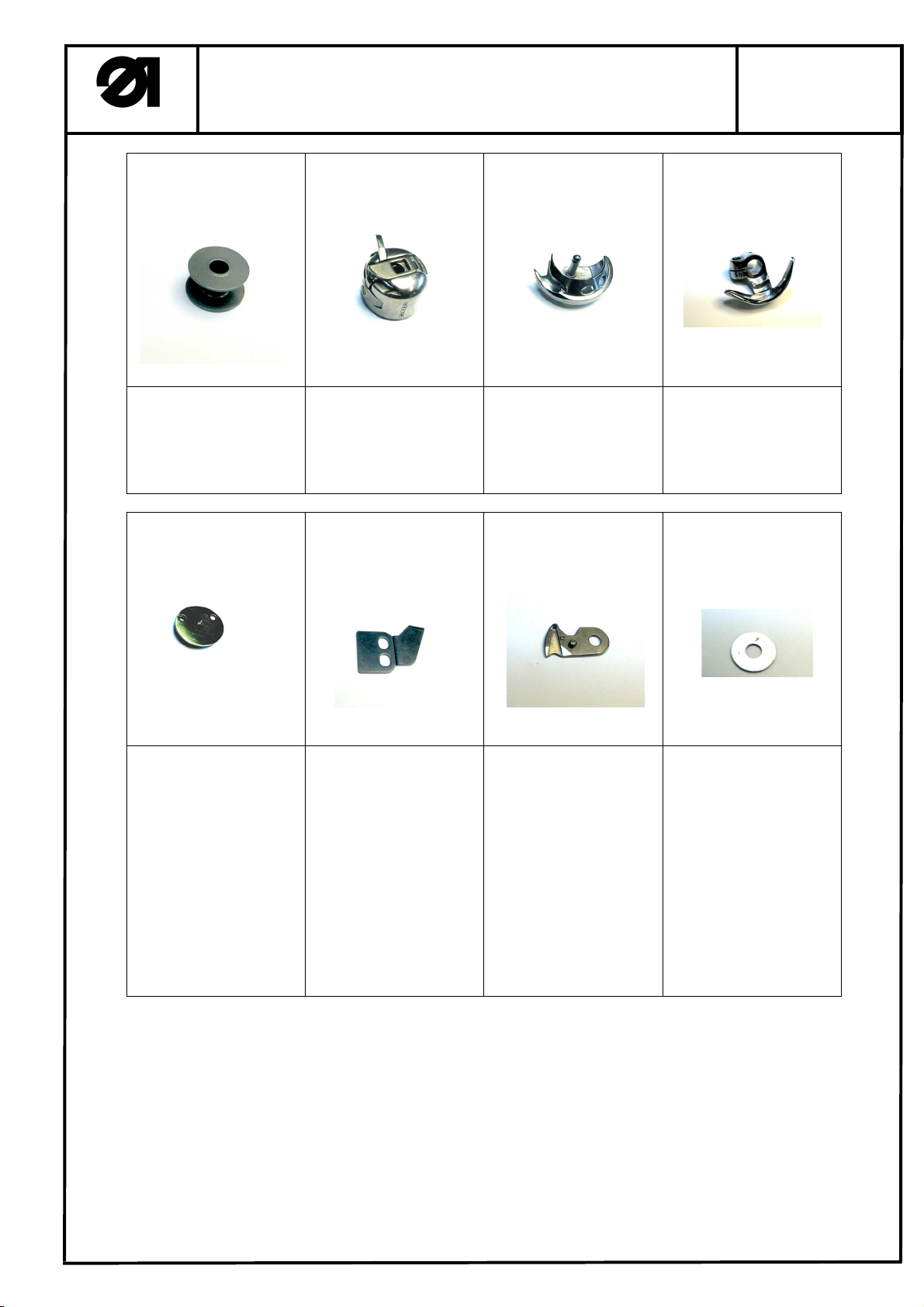
0510 D816-11 (511-211;
511-212)
0510 D816-14 (511-213)
0510 D816-15 Strickware
Knitwear
0510 350180 (511-211;
511-212)
0510 350190 (511-213;
511-214)
0510 350170
(∅2,2 without through)
(∅1,6 without through)
Stichplatteneinsatz
Throat plate insert
0510 350060
Gegenmesser FA
Counter-knife
0510 350033
Hakenmesser
Hooked blade
0510 D816-13-1 (0,8)
0510 D816-13-2 (0,7)
0510 D816-13-3 (0,6)
0510 D816-13-4 (0,5)
Distanzscheibe für Pos.7
Distance washer for pos.7
Page 4
Dürkopp Adler AG
9 10 11 12
Verschleißteile der Klasse 511
Wearing parts of class 511
Part-Nr.: 0791 511800
Edition: 10/2008
Seite 2 / 3
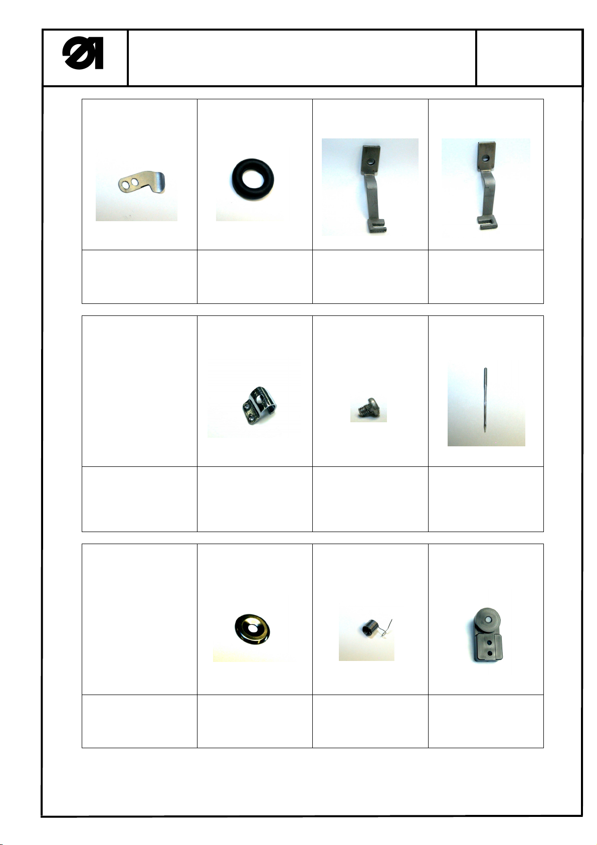
0510 5101204
Abreißmesser
Tear off knife
0510 D281219
Gummiring
Rubber ring
0510 D8.07-15 (511-211)
0510 5101503 (511-212)
0510 D281116 (511-213)
Klammerfuss, links
Clamping foot, left
0510 D8.07-14 (511-211)
0510 5101504 (511-212)
0510 D281115 (511-213)
Klammerfuss, rechts
Clamping foot, right
13 14 15 16
0510 E380207
Fadenführung
Thread guide
0570 092974 a
0510 510G0204 (M3x4)
Schraube für Pos.16
Screw for pos. 16
9092 013400 090
(511-211, 511-212)
9092 013500 120
(511-213)
Nadel
Needle
17 18 19 20
0510 D8.05-15
Spannungsscheibe
Tension disc
0467 110220
0510 5100714 (511-211;
511-212)
0510 5100719 (511-213)
Fadenanzugsfeder
Thread take-up lever
0933 001544
Ölpumpe
Oil pump
Page 5
Dürkopp Adler AG
21 22 23
Verschleißteile der Klasse 511
Wearing parts of class 511
Part-Nr.: 0791 511800
Edition: 10/2008
Seite 3 / 3
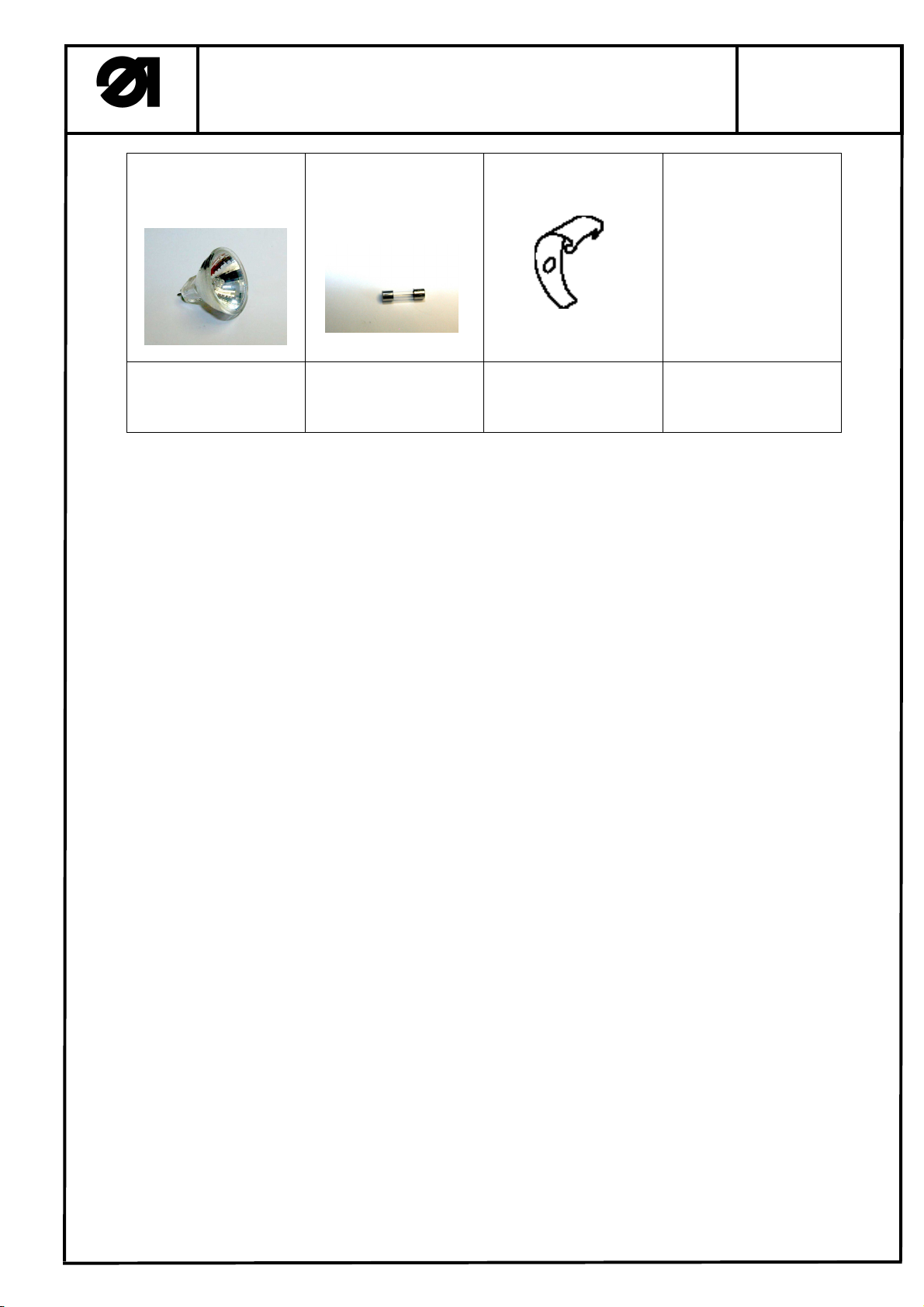
9822 642010
Halogenlampe 12/20W
Halogen bulb 12/20W
9825 810219 (F6,3A)
9825 810417 (T6,3A)
Sicherung
Fuse
0510 150080
Fadenanzugsfeder
Thread take-up spring
Page 6

Page 7
Page 8
Page 9
Page 10
Page 11
Page 12

Page 13
Page 14
Page 15

Page 16

Page 17

Page 18

Page 19

Page 20

Page 21

Page 22

Page 23

Page 24

Page 25

Page 26

Page 27

Page 28

Page 29

Page 30

Page 31

Page 32

Klammersaetze
Clamping sets
511
Ausgabe
Edition
10.08
Blatt
1
Page
Fortsetzung Blatt
Continued page
Einzelteile / Individual Parts
2
Klammer Nr.
Clamping
foot No.
1
2
3
4
5
6
Verwendungszweck / Use
-211; -213; -214
Querriegel / Straight bartack
Standardausstattung Kl. 511-211
Standard equipment for class 511-211
Max. Riegelgroesse / Max. bartack size
19,0 x 3,5 mm
-211; -213; -214
Querriegel / Straight bartack
Standardausstattung Kl. 511-213, 511-214
Standard equipment for class 511-213, 511-214
Max. Riegelgroesse / Max. bartack size
20,0 x 4,1 mm
-211; -213; -214
Querriegel gross / Large straight bartack
Max. Riegelgroesse / Max. bartack size
26,0 x 4,0 mm
-211; -213; -214
Querriegel klein / Small straight bartack
Max. Riegelgroesse / Max. bartack size
9,0 x 3,5 mm
-211; -213; -214
Längsriegel / Longitudinal bartack
Max. Riegelgroesse / Max. bartack size
4,6 x 20,0 mm
-211; -213; -214
Kleinfeld-Klammerfuss / Small field clamping foot
Max. Riegelgroesse / Max. bartack size
18,0 x 11,0 mm
Artikel-Nr. Klammersatz, komplett
Article No. Set of Clamping Foot, cpl.
0510 22 001 4 0510 D8.07-15 0510D8.07-14 0510 D281104 0510 D8.07-16
0510 22 002 4 0510 D281116 0510 D281115
0510 22 003 4 0510 D281107 0510 D281106 0510 D281111 0510 D281128
0510 22 004 4 0510 D8.07-26 0510D8.07-27 0510 D8.07-25 0510 D8.07-16
0510 22 005 4 0510 D281109 0510 D281108 0510 D281112 0510 D281114
0510 22 006 4 0510 D2811330 0510 D2811320 0510 D281139 0510 D281142
Klammerfuss links
Clamp foot left
Klammerfuss rechts
Clamp foot right
Stoffauflageblech
Fabric support plate
0510 D281104
0510 D281117
Fingerschutz
Finger protection
0510 D8.07-16
10
7
8
9
-211; -213; -214
Grossfeld-Klammerfuss / Large field clamping
foot
Max. Riegelgroesse / Max. bartack size
40,0 x 20,0 mm
-212;
Kontraktionsklammer / Contraction clamp
Standardausstattung Kl. 511-212
Standard equipment for class 511-212
Max. Riegelgroesse / Max. bartack size
8,5 x 3,6 mm
-211; -213; -214
Kreis / Circular
Max. Riegelgroesse / Max. bartack size
14,0 x 14,0 mm
-211; -213; -214
D-Klammerfuss Einfach
Simple D-clamping foot
Max. Riegelgroesse / Max. bartack size
11,0 x 8,0 mm
= Aenderung / Modification
0510 22 007 4 0510 51011180 0510 51011170 0510 5101119 0510 D281142
0510 22 008 4
0510 22 009 4 0510 D8.24-2.1 0510 D8.24-1 0510 D281142
0510 22 010 4 0510 D281130 0510 D281129 0510 D281104 0510 D8.07-16
0510 5101503 0510 5101504
Page 33

Klammersaetze
Clamping sets
511
Ausgabe
Edition
10.08
Blatt
2
Page
Fortsetzung Blatt
Continued page
Einzelteile / Individual Parts
3
Klammer Nr.
Clamping
foot No.
11
12
13
14
15
16
Verwendungszweck / Use
Doppel D-Klammerfuss seitlich
Double D-clamping foot lateral
Max. Riegelgroesse / Max. bartack size
8,6 x 11,6 mm
Doppel D-Klammerfuss laengs
Double D-clamping foot longitudinal
Max. Riegelgroesse / Max. bartack size
11,6 x 7,5 mm
Doppel-Tri Klammerfuss seitlich
Double Tri-clamping foot lateral
Max. Riegelgroesse / Max. bartack size
12,9 x 11,2 mm
Guertelschlaufe
Belt loop
Max. Riegelgroesse / Max. bartack size
16,0 x 2,6 mm
Klammerfuesse zum Selbstanfertigen
Clamping feet for self-producing
Max. Riegelgroesse / Max. bartack size
40,0 x 20,0 mm
Doppel-D-Riegel seitlich
Double D bartack lateral
Max. Riegelgroesse / Max. bartack size
8,6 x 13,6 mm
Artikel-Nr. Klammersatz, komplett
Article No. Set of Clamping Foot, cpl.
0510 22 011 4 0510 5101120 0510 5101121 0510 5101122 0510 D281128
0510 22 012 4 0510 5101124 0510 5101125 0510 5101129 0510 D281142
0510 22 013 4 0510 5101126 0510 5101127 0510 5101128 0510 D281142
0510 22 014 4 0510 5101115 0510 5101114 0510 5101116 0510 D8.07-16
0510 22 015 4 0510 51011310 0510 51011300 0510 5101132 0510 D281142
0510 22 016 4 0510 5101140 0510 5101142 0510 D281128
Klammerfuss links
Clamp foot left
Klammerfuss rechts
Clamp foot right
Stoffauflageblech
Fabric support plate
Fingerschutz
Finger protection
17
18
Rohling + Bearbeitung nach Kundenwunsch
(Kreise + Rechtecke)
Blank + customized
(Circle + rectangle)
Max. Riegelgroesse / Max. bartack size
40,0 x 20,0 mm
Rohling + Bearbeitung nach Kundenwunsch
(Polylines)
Blank + customized
(Polylines)
Max. Riegelgroesse / Max. bartack size
40,0 x 20,0 mm
0510 22 017 4 0510 220154
0510 22 018 4 0510 220154
= Aenderung / Modification
Page 34

1
Klammersaetze
Clamping sets
511
Ausgabe
Edition
10.08
Blatt
Page
3
Fortsetzung Blatt
Continued page
4
Max. Riegelgroesse - siehe Tabelle / Max. bartack size - see table
2
Max. Riegelgroesse - siehe Tabelle / Max. bartack size - see table
Page 35

3
Klammersaetze
Clamping sets
511
Ausgabe
Edition
10.08
Blatt
Page
4
Fortsetzung Blatt
Continued page
5
Max. Riegelgroesse - siehe Tabelle / Max. bartack size - see table
4
Max. Riegelgroesse - siehe Tabelle / Max. bartack size - see table
5
Max. Riegelgroesse - siehe Tabelle / Max. bartack size - see table
Page 36

6
Klammersaetze
Clamping sets
511
Ausgabe
Edition
10.08
Blatt
Page
5
Fortsetzung Blatt
Continued page
6
Max. Riegelgroesse - siehe Tabelle / Max. bartack size - see table
7
Max. Riegelgroesse - siehe Tabelle / Max. bartack size - see table
8
Max. Riegelgroesse - siehe Tabelle / Max. bartack size - see table
Page 37

9
Klammersaetze
Clamping sets
511
Ausgabe
Edition
10.08
Blatt
Page
6
Fortsetzung Blatt
Continued page
7
Max. Riegelgroesse - siehe Tabelle / Max. bartack size - see table
10
Max. Riegelgroesse - siehe Tabelle / Max. bartack size - see table
11
Max. Riegelgroesse - siehe Tabelle / Max. bartack size - see table
Page 38

12
Klammersaetze
Clamping sets
511
Ausgabe
Edition
10.08
Blatt
Page
7
Fortsetzung Blatt
Continued page
8
Max. Riegelgroesse - siehe Tabelle / Max. bartack size - see table
13
Max. Riegelgroesse - siehe Tabelle / Max. bartack size - see table
14
Max. Riegelgroesse - siehe Tabelle / Max. bartack size - see table
Page 39

15, 17, 18
Klammersaetze
Clamping sets
511
Ausgabe
Edition
10.08
Blatt
Page
8
Fortsetzung Blatt
Continued page
--
Max. Riegelgroesse - siehe Tabelle / Max. bartack size - see table
16
Max. Riegelgroesse - siehe Tabelle / Max. bartack size - see table
Page 40

1 2 3 4 6
5 7 8 9 10
H10
Z
Steuerung k DAC4,Kl.511
9850 511010
control DAC4,cl.511
Encoder Nähmotor
encoder sewing motor
GND
G1
G2
+5V
(9pol.)
1
2
3ge4
5
X102
gn
bn
678
ws
Nähleuchte
sewing light
Steuerung k DAC4,Kl.531
9850 531010
control DAC4,cl.531
Nähmotor
sewing motor
SYNC
9
gr
Schirm
(5pol.)
X101
1
Schirm
X1
bn
L
bl
N
gnge
PE
bn
bl
gnge
Netzstecker
mains plug
Leitung k
9870 001020
Schrittmotor X-Achse
stepping motor X-axis
PH_X_A1
PH_X_A2
GND
GND
(6pol.)
1
4
5
2
X105
rt
3
gn
Schirm
bl
Steckdose
wall socket
Z
ASC0-Schnittstelle/Pos.Signale
Leitung k
9870 001021
Pedal/CAN
ASC0-Interface/encoder signals
PE
W
V
U
PE
2
3
4
5
bn
bl
sw
gnge
X103
(9pol.)
G2OUT/IN
TxD TTL2RxD TTL
1
ge
+5V
GND
G1OUT/IN
Ext. SYNC
LSM IN
Pos.2OUT
3
4
5
6
7
8
9
gn
ws
bn
Schirm
X104
(9pol.)
GND
1
gr
CAN High
2
+10% -20%
pedal/CAN
CAN Low
Pedal C
+5V
3A
4
5C
6
ws
gn
pedal B
50/60Hz
pedal D
pedal A
7
8
ge
bn
230V
Bootload
9
Schirm
X0
A1
L1
N
PE
PH_X_B2
PH_X_B1
6
ge
bn
bl
gnge
bn
bl
gnge
Hauptschalter
main switch
Q0
T1L1
T2L2
PE
bn
bl
gnge
Schrittmotor Y-Achse
stepping motor Y-axis
PH_Y_A1
PH_Y_A2
GND
GND
PH_Y_B2
PH_Y_B1
(6pol.)
1
4
5
2
3
SchirmSchirm
blbl
6
gege
X106
rtrt
gngn
F1
M8,0A
Netz
power
F2
M8,0 A
E
X102
M
X101
X103
(X)
X105
(Y)
X106
9870 511001 CN L004
Blatt 4
sheet
Nähmotor
sewing motor
A4
M1M1.1
1/2.....12
Pedal 9800 330012
pedal
S14
S15
S16
S17
GND
Pedal-
D
C
B
stufe:
B
D
1/2
0
-1
-2
A
-2
H
H
L
L
-1
H
H
H
L
0
H
H
H
H
H
H
L
H
1
H
L
L
H
2
H
L
L
L
3
H
L
H
L
4
H
L
H
H
5
L
L
H
H
6
L
L
H
L
7
L
L
L
L
8
L
L
L
H
9
L
H
L
H
10
L
H
L
L
11
L
H
H
L
12
L
H
H
H
M M
M2
X-Achse
X-axis
M3
Y-Achse
Y-axis
Z
Zusatzeinrichtung
optional equipment
c
b
a
Änderung Datum
Datum
Bearb.
Gepr.
NormName
04.11.08
Cz
D PPÜR KO
ADLER AG
Bielef eld
Teilefamilie
Freigabe
/0084 07
511/531
Steuerung DAC4, Nähantrieb, Schrittmotore
control DAC4, sewing motor, stepper
Bauschaltplan 9890 511001 B
Blatt
/1 7
Page 41

1 2 3 4 6
5 7 8 9 10
Steuerung k DAC4,Kl.511
9850 511010
control DAC4,cl.511
(37pol.)
X108
IN_ANA_1
+5V_Efka
IN_ANA_2
GND_Case
IN_5
IN_3
IN_1
IN_4
IN_7
IN_8
IN_2
IN_6
IN_9
M12 (24V/0,5A)
M13 (24V/3A/PWM)
I/O 1
M16 (24V/0,5A)
M17 (24V/0,5A)
Ein-/Ausgänge 1
M18 (24V/0,5A)
M7 (24V/0,5A)
M8 (24V/0,5A)
M9 (24V/0,5A)
M14 (24V/0,5A)
M3 (24V/3,0A)
M2 (24V/0,5A)
M10 (24V/0,5A)
M6 (24V/0,5A)
M11 (24V/0,5A)
M5 (24V/0,5A)
VR (24V/6,5A/PWM)
FL (24V/6,5A/PWM)
M4 (24V/4A/PWM)
IN_10
+24V
+24V
GND_Case
+24V
M1 (24V/4A)
Steuerung k DAC4,Kl.531
9850 531010
control DAC4,cl.531
grrs
rtbl
wsgn
bngn
wsge
gebn
wsgr
grbn
wsrs
rsbn
wsbl
bnbl
wsrt
bnrt
wssw
bnsw
grgn
gegr
rsgn
gers
gnbl
gebl
gnrt
gert
gnsw
gesw
ws
bn
gn
ge
gr
rs
bl
rt
sw
vi
I/O .1
X108
1
2
3
4
5
6
7
8
9
10
11
12
13
14
15
16
17
18
19
20
21
22
23
24
25
26
27
28
29
30
31
32
33
34
35
36
37
A1
9870 511001 CN L001
Blatt 4
sheet
IN_2_TTL
I/O 2PWM
IN_3_TTL
Ein-/Ausgänge 2PWM
IN_4_TTL
IN_1_24V
IN_2_24V
IN_3_24V
IN_4_24V
PWM_OUT_1
PWM_OUT_1
PWM_OUT_1
PWM_OUT_1
+5V
GND
+24V
GND
IN_1_TTL
OUT_1
OUT_2
OUT_3
OUT_4
OUT_5
OUT_6
OUT_7
OUT_8
+24V
RxD
TxD
+5V
GND
+24V
GND
+48V
+48V
+48V
+48V
(25pol.)
X109
(25pol.)
X110
(9pol.)
+5V
MTST
CLK
GND
T4IN
GND
GND
GND
BOOT
RxDBF-
TxDBF+
GND
+24V
GND
RxDBF+
TxDBF-
GND
+24V
X111
(15pol.)
X107
1
2
3
4
5
6
7
8
9
memo dongle
Bedienfeld BF3
1
2
3
4
5
6
7
8
9
10
11
12
13
14
15
Schirm
bl
gn
ws
gr
sw
Panel
X170
rt
ge
bn
rs
Leitung k
9870 579025
ws
bn
gn
ge
gr
rs
bl
rt
sw
Schirm
(9pol.)
X201
9850 001066
control panel
A2
1
Rx+
2
Rx-
3
Tx-
4
Tx+
5
GND
6
GND
7
8
RESET
9
+24V
grrs
rtbl
wsgn
bngn
wsge
gebn
wsgr
grbn
wsrs
rsbn
wsbl
bnbl
wsrt
bnrt
grrs
rtbl
ws
bn
gn
ge
gr
rs
bl
rt
sw
vi
I/O .2
X109
9870 511001 CN L002
Blatt 4
test interfacecontrol panel
Diag-SchnittstelleBedienfeld
sheet
ws
bn
gn
ge
PWM
gr
rs
X110
bl
rt
sw
vi
9870 511001 CN L003
Blatt 6
sheet
/RESTERM
1
2
3
4
5
6
7
8
9
10
11
12
13
14
15
16
17
18
19
20
21
22
23
24
25
1
2
3
4
5
6
7
8
9
10
11
12
13
14
15
16
17
18
19
20
21
22
23
24
25
Z
Zusatzeinrichtung
optional equipment
c
b
a
Änderung Datum
Datum
Bearb.
Gepr.
NormName
04.11.08
Cz
D PPÜR KO
ADLER AG
Bielef eld
Teilefamilie
Freigabe
/0084 07
511/531
Steuerung DAC4, I/O, Bedienfeld
control DAC4, I/O, control panel
Bauschaltplan
9890 511001 B
Blatt
/2 7
Page 42

1 2 3 4 6
5 7 8 9 10
A1
Steuerung k
DAC4,Kl.511
9850 511010
control
DAC4,cl.511
Steuerung k
DAC4,Kl.531
9850 531010
control
DAC4,cl.531
X101 X102
M1
M E
X101
sewing
motor
Attention,
before connecting or disconnecting
any plug, switch off the main supply!
X105
X105
(X)
M2
X111
F1 M8,0A
F2 M8,0A
M1.1
9870 511001 CN L004
9870 511001 CN L001
X103
X108
I/O .1
X102
encoder
sewing
motor
X103
X108
X104
X109
step motor X
X106
step motor Y
X107
control
X110
panel
X170
X106
X110
(Y)
Panel
PWM
Pedal
9800 330012
M3
Leitung k
9870 579025
9870 511001 CN L003
memo dongle
c
b
a
Änderung Datum
Datum
Bearb.
Gepr.
NormName
04.11.08
Cz
D PPÜR KO
ADLER AG
Bielef eld
I/O
Teilefamilie
Freigabe
/0084 07
I/O PWM
511/531
Steuerung DAC4, Anschlußplan
control DAC4, connection diagram
X109
I/O .2
9870 511001 CN L002
Bauschaltplan
9890 511001 B
Blatt
/3 7
Page 43

1 2 3 4 6
5 7 8 9 10
9870 511001 CN L001
Blatt 2
sheet
9870 511001 CN L004
Blatt 1
sheet
9870 511001 CN L002
Blatt 2
sheet
X202 X2
ws
bn
gn
ge
gr
rs
bl
rt
sw
vi
grrs
rtbl
wsgn
bngn
wsge
gebn
wsgr
grbn
wsrs
rsbn
wsbl
bnbl
wsrt
bnrt
wssw
bnsw
grgn
gegr
rsgn
gers
gnbl
gebl
gnrt
gert
gnsw
gesw
X213 X13
ws
bn
gn
ge
X201 X1
ws
bn
gn
ge
gr
rs
bl
rt
sw
vi
grrs
rtbl
wsgn
bngn
wsge
gebn
wsgr
grbn
wsrs
rsbn
wsbl
bnbl
wsrt
bnrt
1
IN_ANA_1
2
+5V_Efka
3
IN_ANA_2
4
GND
5
IN_5
6
IN_3
7
IN_1
8
IN_4
9
IN_7
10
IN_8
11
IN_2
12
IN_6
13
IN_9
14
IN_10
15
M12
16
+24V
17
+24V
18
M13 FA
19
GND
20
M16
21
M17
22
M18
23
M7
24
M8
25
M9
26
M14
27
M3
28
M2
29
M10
30
M6
31
M11
32
M5
33
+24V
34
VR
35
FL
36
M4 FS
37
M1 FW/FK
1
GND
2
N-Ref
3
+5V_EFKA
4
1
+5V
2
GND
3
+24V
4
GND
5
IN_1_TTL X-Ref
6
IN_2_TTL Y-Ref
7
OUT_1
8
OUT_2
9
OUT_3
10
OUT_4
11
OUT_5
12
OUT_6
13
OUT_7
14
OUT_8
15
+24V
16
IN_3_TTL
17
IN_4_TTL
18
IN_1_24V
19
IN_2_24V
20
IN_3_24V
21
IN_4_24V
22
23
24
IN_8
IN_9
IN_10
IN_1_24V
IN_2_24V
IN_3_24V
IN_4_24V
+24V
IN_1
IN_2
IN_3
IN_4
IN_5
IN_6
IN_7
GND
X7
2
3
4
5
6
7
X6
1
2
3
4
5
6
7
X5
1
2
3
4
5
6
7
X4
1
2
3
4
5
6
7
A3
X20
X21
X22
1
1
X13
X14
X15
1
bn
DA196
2
X1
1
7
7
1
1
X4
X5
X6
X7
12
1
12
Taster k 9880 511003
X16
1
1
37
19
1
X2
X8
X9
X10
button
ws
1
bn
0
gn
2
X17
A8
IN_1
+24V
IN_1
1
X18
X19
1
1
1
20
1
2
X3
1
1
X11
X12
1
Z
+5V_Efka
IN_ANA_1
+5V
"1"
S1
+24V
IN OUT
S2
GND
IN_4_TTL
"2"
+24V
OUT_3
GND
+24V
OUT_2
GND
+24V
Out_1
GND
GND
GND
X22 X222
2
3
2
3
X20 X220
2
3
ws
1
bn
gn
X221X21
ws
1
bn
gn
ws
1
bn
gn
X19
1
2
3
X18
1
2
3
X17
Leiterplatte 9850 511001 CN
PCB
Lasermarkierung
laser-marker
Z
Blatt 6
sheet
Blatt 5
sheet
1
ws
gn
IN_3_TTL
IN_2_TTL
IN_1_TTL
REF_NM
GND
GND
GND
+24V
GND
2
3
X16 X216
1
2
3
X215X15
1
2
3
X214X14
1
2
3
1
2
3
1
2
3
(Y-Ref)
S26
Ref. Y-Achse
ref. Y-axis
(X-Ref)
S25
Ref. X-Achse
ref. X-axis
(3pol.)
gn
bl
ws
bl
ws
gn
X416
GND
REF_Y
+5V
(3pol.)
ge
sw
rt
sw
rt
ge
X415
GND
REF_X
+5V
(N-Ref)
bn
bl
9870 511001 CN L006
REF_NM
replacement switch
S12
Ref. Nähmotor
ref. sewing motor
9815 710105
Z
Zusatzeinrichtung
optional equipment
c
b
a
Änderung Datum
Datum
Bearb.
Gepr.
NormName
04.11.08
Cz
D PPÜR KO
ADLER AG
Bielef eld
Teilefamilie
Freigabe
/0084 07
511/531
Eingänge
inputs
Bauschaltplan
9890 511001 B
Blatt
/4 7
Page 44

1 2 3 4 6
Leiterplatte 9850 511001 CN
PCB
5 7 8 9 10
Blatt 4
sheet
+24V
OUT_3
GND
+24V
OUT_2
GND
X22 X222
X21 X221
ws
1
bn
2
gn
3
ws
1
bn
2
gn
3
Z
Leitung k
9870 511011
Z
Leitung k
9870 511011
ws
bn
gn
ws
bn
gn
(3pol.)
+24V
Y23
GND
(3pol.)
+24V
Y22
GND
Leiterplatte k 9850 001090
PCB
A7
X1X241
1
U_IN
2
on/off
3
GND_IN
X241
+VCC
A7
Leiterplatte k 9850 001090
PCB
A6
X1X243
1
U_IN
2
on/off
3
GND_IN
+VCC
0V
0V
(2pol)
X242
(2pol)
Z
X2
ws
sw
Z
X2
ws
sw
X242
X244
ws
sw
ws
sw
ws
sw
ws
sw
ws
sw
ws
sw
(*1)
(*1)
(*1)
(*1)
(*1)
(*1)
(2pol.)
X431
ws
sw
(2pol.)
X432
ws
sw
(2pol.)
X433
ws
sw
(2pol.)
X428
ws
sw
(2pol.)
X429
ws
sw
Lasermarkierung 3 schaltbar mit Ausgang Y23
laser marker 3 switchable with output Y23
ws
1
sw
2
ws
1
sw
2
ws
1
sw
2
H3
H3.1
H3.2
Laser 3
laser 3
Laser 3.1
laser 3.1
Laser 3.2
laser 3.2
Z
zusätzl. Option 1
Z
additional option 1
zusätzl. Option 2
Z
additional option 2
Lasermarkierung 2 schaltbar mit Ausgang Y22
laser marker 2 switchable with output Y22
ws
1
sw
2
ws
1
sw
2
H2
H2.1
Laser 2
laser 2
Laser 2.1
laser 2.1
Z
zusätzl. Option 1
Z
additional option 1
Z
X220X20
ws
1
+24V
Out_1
GND
Laser k laser cpl.(*1) 9835 501005
Ersatzlaser replacement laser 9835 501006
bn
2
gn
3
Leitung k
9870 511011
ws
bn
gn
(3pol.)
+24V
Y21
GND
X243
A6
Leiterplatte k 9850 001090
PCB
A5
X1X245
1
U_IN
2
on/off
3
GND_IN
X245
+VCC
A5
0V
X244
(2pol)
X246
Z
X2
ws
sw
X246
ws
sw
ws
sw
ws
sw
(*1)
(*1)
(*1)
(2pol.)
X430
ws
sw
(2pol.)
X425
ws
sw
(2pol.)
X426
ws
sw
(2pol.)
X427
ws
sw
ws
1
sw
2
H2.2
Laser 2.2
laser 2.2
zusätzl. Option 2
Z
additional option 2
Lasermarkierung 1 schaltbar mit Ausgang Y21
laser marker 1 switchable with output Y21
ws
1
sw
2
ws
1
sw
2
ws
1
sw
2
H1
H1.1
H1.2
Laser 1
laser 1
Laser 1.1
laser 1.1
Laser 1.2
laser 1.2
Z
zusätzl. Option 1
Z
additional option 1
zusätzl. Option 2
Z
additional option 2
Z
Zusatzeinrichtung
optional equipment
c
b
a
Änderung Datum
Datum
Bearb.
Gepr.
NormName
04.11.08
Cz
D PPÜR KO
ADLER AG
Bielef eld
Teilefamilie
Freigabe
/0084 07
511/531
Lasermarkierung
laser-marker
Bauschaltplan
9890 511001 B
Blatt
/5 7
Page 45

1 2 3 4 6
5 7 8 9 10
Blatt 4
sheet
IN_ANA_2
+ -
ACS712
M4
Fadenspannung Regelung
thread tension control
A3
Leiterplatte 9850 511001 CN
DA196
PCB
2
1
7
7
X13
X14
X1
1
1
X4
X5
X6
X7
12
1
12
X20
1
X15
X16
1
1
37
19
X8
X9
X10
511-211/ -212/ -213/ -214, 531-211
M1
M2
M3
FS
M5
M6
M7
M8
M9
M10
M11
M12
X8
10
11
12
1
ws
2
3
bl
4
ws
5
ws
6
7
8
9
+24V
X9
1
X21
X22
1
1
X17
X18
1
X2
X19
1
1
1
20
1
2
X3
1
1
X11
X12
1
2
3
4
5
6
7
8
9
10
11
12
rt
bn
bn
bn
bn
bl
sw
bl
sw
Leitung k
9870 367003
Leitung k
9870 367003
9870 511001 CN L007
Leitung k
9870 367003
ws
bn
ws
bn
bn
bl
Y1
Y1
Y5
Y6
Y4
Y13
Fadenklemme
thread clamp
Fadenwischer
thread wiper
Klammerfuss geteilt 1
clamping foot shared 1
Klammerfuss geteilt 2
clamping foot shared 2
(PWM 3)
Fadenspannung
thread tension
(PWM 2)
Faden abschneiden
cut the thread
(Standard 511)
(standard 511)
(Variante 511)
(variant 511)
(Standard 531)
(standard 531)
Z
Z
Y6Y2
ZY5Z
Z
9870 511001 CN L003
Blatt 2
sheet
ws
bn
gn
ge
gr
rs
bl
rt
sw
vi
grrs
rtbl
M13
M14
M16
M17
M18
VR
FL
OUT_4
OUT_5
X3X203
+5V
1
GND
2
+24V
3
GND
4
PWM_OUT_1
5
PWM_OUT_1
6
PWM_OUT_1
7
PWM_OUT_1
8
+48V
9
+48V
10
+48V
11
+48V
12
13
14
15
16
OUT_6
OUT_7
OUT_8
X10
1
2
3
4
5
6
7
8
9
10
11
12
X11
1
X12
1
c
Z
Zusatzeinrichtung
optional equipment
b
a
Änderung Datum
sw
sw
bl
Datum
Bearb.
Gepr.
NormName
04.11.08
Cz
D PPÜR KO
ADLER AG
Bielef eld
Teilefamilie
Freigabe
/0084 07
511-212
ws
bn
Y2
Klammerfuss pneu. (Variante 2)
clamping foot pneu. (variant 2)
511-211/ -213/ -214, 531-211
ws
bn
Y2
Y31
Klammerfuss pneu. (Variante 2)
clamping foot pneu. (variant 2)
(PWM 1)
Klammerfussmagnet (Variante 1)
clamping foot solenoid (variant 1)
511/531
Ausgänge
outputs
Bauschaltplan
9890 511001 B
Blatt
/6 7
Page 46

1 2 3 4 6
5 7 8 9 10
Ansicht von oben
9870 511001 CN L008
9870 511001 CN L009
top view
gr
Nähkopf
sewing head
Steuerung k DAC4
gr
control DAC4
c
b
a
Änderung Datum
Datum
Bearb.
Gepr.
NormName
04.11.08
Cz
D PPÜR KO
ADLER AG
Bielef eld
Teilefamilie
Freigabe
/0084 07
511/531
Teileliste, Potentialausgleich
parts list, operational bondings
Bauschaltplan
9890 511001 B
Blatt
/7 7
 Loading...