

Page 1
OG7508A2
ECN 12490, Rev A 01/06/16
Dynamic Transducers and Systems
21592 Marilla St. • Chatsworth, CA 91311 • Phone 818-700-7818
www.dytran.com • e-mail: info@dytran.com
OPERATING GUIDE
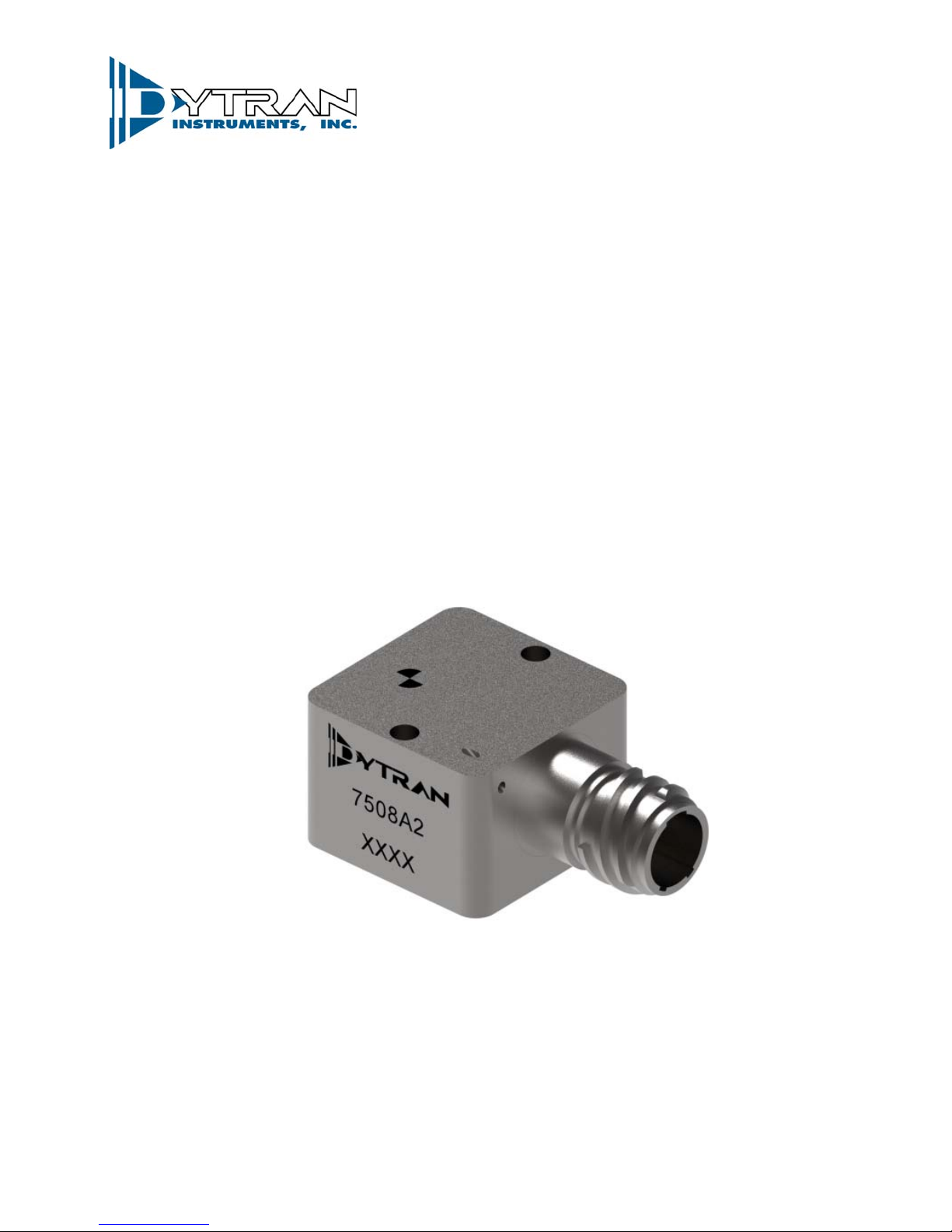
MODEL 7508A2
Variable Capacitance Accelerometer with
CVLD (Constant Voltage Line Driver) Interface
Page 2

OPERATING GUIDE
MODEL 7508A2 ACCELEROMETER
INTRODUCTION
Dytran model 7508A2 is a high-performance,
wide temperature range, variable capacitance (VC)
accelerometer intended to directly replace CVLD units
for existing or new applications. This accelerometer
utilizes a capacitive sensing element and an advanced
electrical circuitry to simulate the operation of a CVLD
sensor. It combines an integrated VC accelerometer
chip with high-drive, low-impedance buffering for
measuring acceleration in commercial and industrial
environments. It is tailored for zero-to-medium
frequency instrumentation applications. This module
contains a hermetically sealed micromachined
capacitive sensing element, a custom integrated circuit
amplifier, and current output stages. The hermetically
sealed titanium case has a Glenair Series 805 MightyMouse, 3-pin receptacle, and is easily mounted via
two 4-40 screws. It is relatively insensitive to
temperature changes and thermal gradients. The
power signal and ground wires are isolated from the
case. An initial calibration sheet is included and
periodic calibration checking is available.
OPERATION
Model 7508A2 accelerometer modules
produce an analog current output which varies with
acceleration. The sensitive axis is perpendicular to
the bottom of the package, with positive acceleration
defined as a force pushing on the bottom of the
package. The signal output current oscillates about a
bias current (14-15 mA) which provides dynamic
acceleration information. The output scale factor and
the bias current are independent from the supply
voltage of 10 to 36 volts. At zero acceleration, the
output current is nominally 14-15 mA. At ± full scale
acceleration, the output current is ±5mA from the bias
current stated on the calibration certificate.
NOTE: After powering the unit, allow 3-5 minutes
for the unit to stabilize before taking readings.
CABLE LENGTH CONSIDERATIONS
Cable lengths of up to 15 meters (50 feet) can
be used with the 7508A2 accelerometer. For lengths
longer than 15 meters, we recommend you check
each individual installation for oscillation by tapping
the accelerometer and watching the current output for
oscillation in the 20kHz to 50kHz region. If no
oscillation is present, then the cable length being used
is acceptable. From the standpoint of output current
drive and slew rate limitations, model 7508A2 is
capable of driving over 600 meters (2000 feet) of its
cable type, but at some length between 15 and 600
meters, each device will likely begin to exhibit
oscillation.
ABOUT CVLD INTERFACE
The basic idea of the CVLD (Constant Voltage
Line Driver) interface is accomplished by changing the
signal carrier from voltage to current. The CVLD is
similar to IEPE in regard that CVLD is also a two wire
sensor, meaning that the sensor is powered and the
signal is extracted through the same wire. Unlike
IEPE, no current limitation is required, as the sensor
regulates the current internally and is changing it in
accordance with applied acceleration. Therefore, by
monitoring the current, one can always receive the
acceleration information.
The CVLD sensor is compatible with 4-20mA
signal loops. When using the CVLD sensor with a
standard 4-20mA loop equipment the signal must be
interpreted differently. A 4-20mA interface is designed
such that 4mA current designates zero measurand
and when used with accelerometers, the increase in
current shows the increase in RMS or peak
acceleration. In other words, a typical 4-20mA loop
accelerometer does not provide dynamic acceleration,
but rather its RMS or peak representation. In case of
CVLD sensor, the bias current (14-15mA, the exact
value can be found on the calibration certificate)
designates zero measurand which allows for dynamic
signal representation.
The advantages of using the CVLD
accelerometers are lower noise, high immunity to
EMI/EMC interference, simplified wiring (only two
wires: power and ground are required), and long cable
runs.
Page 3
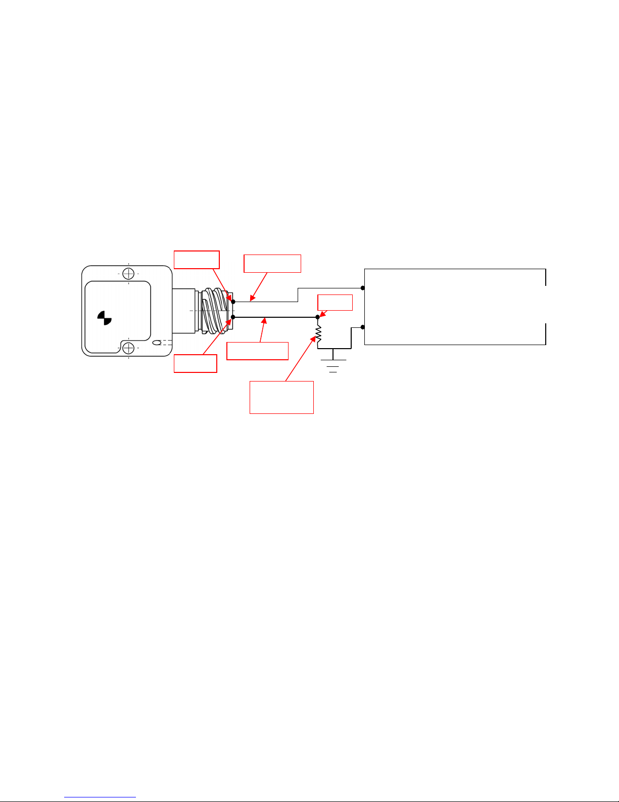
GROU
Vout
MAINTENANCE AND REPAIR
Should you experience a problem with your
system, contact the Dytran factory for technical
assistance with analysis and troubleshooting. If the
product must be returned for evaluation and/or repair,
you will be given an RMA (returned materials
authorization) number and instructions for
returning the instrument to the factory. Do not return
the instrument without first obtaining this authorization
to return.
PIN 1
POWER
ND
PIN 2
SENSE
RESISTOR
Figure 2: Connection Diagram
POWER
GROUND
POWER SUPPLY
(10-36 VDC)
 Loading...