

Model Number
Y
X
2
y
2
10000HZ
0.000008
Grms/√(Hz)
0.00008
m/s
rms/√(Hz)
y
2
2
2
°
°
pply
]
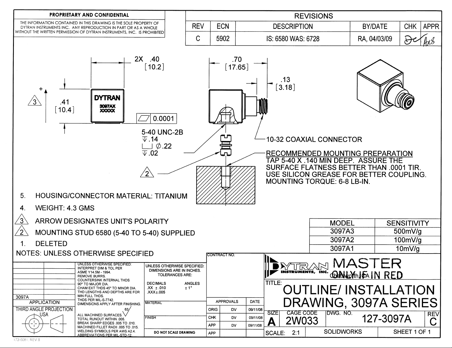
3097A2 PS3097A2
PERFORMANCE SPECIFICATIONS
IEPE ACCELEROMETER
This family also includes:
• MINIATURE SIZE
• HERMETICALLY SEALED
• EXCELLENT LINEARIT
Model Sensitivity (mV/g)
3097A1 10 0.3 to 5,000 1.5 to 2.5
3097A3 500 0.3 to 5,000 1.5 to 2.5
Refer to the performance specifications of the products in this family for detailed description
Supplied Accessories:
PHYSICAL 2) Model 6580 mounting stud (5-40 to 5-40), qty 1
ENGLISH SI
Weight 0.15 oz 4.3 grams Notes:
Connector [1] Type 10-32 10-32 [1] Coaxial, 10-32 connector. Mates with Dytran cable Model 6010AXX or 6011AX
Mounting Provision
Material, Housing/Connector
Sensing Element CERAMIC CERAMIC
Element Style PLANAR SHEAR PLANAR SHEAR
PERFORMANCE
Sensitivity, ±5 % [2]
Range for ± 5 Volts Output
Frequency Response, ±5%
±15%
Resonant Frequenc
Broad Band Resolution
Spectral Noise
Linearity [2]
Maximum Transverse sensitivit
Strain Sensitivity @ 250µε
Phase Response ±5° 5 to 3000 Hz 5 to 3000 Hz
ENVIRONMENTAL
Maximum V ibrati on
Maximum S hock
Temperature Range -60 to 180
Seal
ELECTRICAL
Su
Current Range [3
Compliance Voltage Range
Output Impedence,Typ 100 Ω 100 Ω
Bias Voltage
Discharge Time Constant
Tapped Hole 5-40 UNC-2B 5-40 UNC-2B
1Hz 0.00006
10Hz 0.00001
100Hz 0.00004
1000Hz 0.000002
TITANIUM TITANIUM
100 mV/G 10
50 G peak 491
0.3 to 5,000 Hz 0.3 to 5,000 Hz
0.15 to 10,000 Hz 0.15 to 10,000 Hz
> 35 kHz > 35 kHz
0.0004
±1
5
0.002 G/με 0.02
400 G peak 3924
5000 G peak 49050
HERMETIC HERMETIC
2 to 20 mA 2 to 20 mA
+18 to +30 Volts +18 to +30 Volts
+11 to +13 VDC +11 to +13 VDC
1.5 to 2.5 Sec 1.5 to 2.5 Sec
G rms 0.004
Grms/√(Hz)
Grms/√(Hz)
Grms/√(Hz)
Grms/√(Hz)
% F.S. ±1 % F.S.
%5%
F
0.001
0.0001
0.00039
0.00002
-51 to 82
m/s
m/s
m/s
m/s
m/s
m/s
mV/m/s
m/s
m/s
rms
2
rms/√(Hz)
2
rms/√(Hz)
2
rms/√(Hz)
2
rms/√(Hz)
2
/µε
m/s
peak
peak
C
1) Accredited calibration certificate (ISO 17025)
[2] Measured at 100Hz, 1 Grms per ISA RP 37.2.
[3] Measure using zero-based straight line method, % of F.S. or any lesser range.
[5] Do not apply power to this system without current limiting, 20 mA MAX. To do so will destroy the IC charge amplifier.
[6] In the interest of constant product improvement, we reserve the right to change spec ifications without notice.
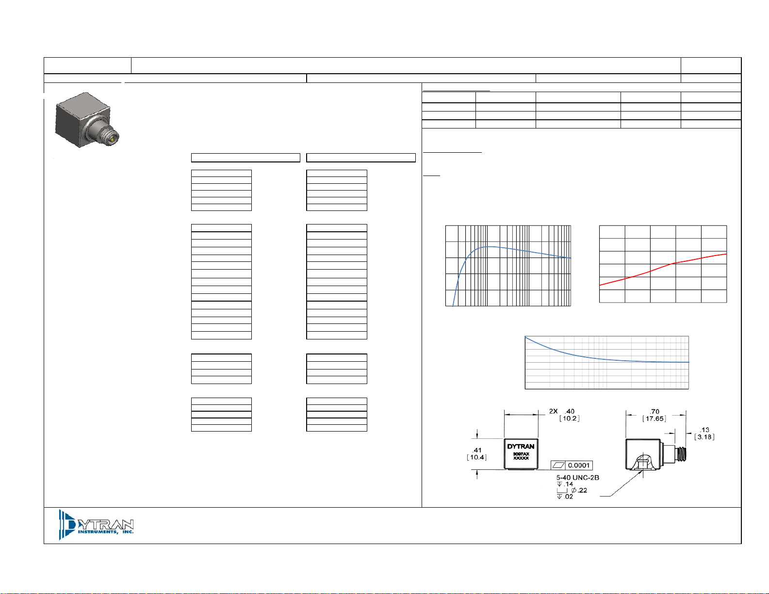
TYPICAL LOW FREQUENCY RESPONSE
10
2
10
5
5
0
0
-5
-5
SENSIT IVITY DEVIATION (% )
SENSIT IVITY DEVIATION (% )
-10
-10
-15
-15
0.1 1 10 100
TYPICAL LOW FREQUENCY RESPONSE
FREQUENCY (HZ)
Phase Shift (degrees)
Frequency Response ±5%,(Hz)
30
30
20
20
10
10
0
0
-10
-10
SENSIT IVITY DEVIATION (% )
SENSIT IVITY DEVIATION (% )
-20
-20
-30
-30
-60 -12 36 84 132 180
40
30
20
10
0
-10
-20
-30
-40
0.4 4 40
TYPICAL PHASE RESPONSE
Frequency (Hz)
REV C, ECN 7213 , 11/16/10
Time Constant (Sec)
TYPICAL TEMPERATURE RESPONSE
TYPICAL TEMPERATURE RESPONSE
TEMPERATURE ( °F)
Operating Temp (°F)
DOC NO
-60 to 200
-60 to 150
Units on the line drawing are in inche s, units in brack ets are in millim eters. Refe r to 127-309 7A for more inf ormation.
21592 Marilla Street, Chatsworth, California 91311 Phone: 818.700.7818 Fax:818.700.7880 www.dytran.com
For permission to reprint this content, please contact info@dytran.com
 Loading...