

Page 1
Dynamic Transducers and Systems
21592 Marilla St. • Chatsworth, CA 91311 • Phone 818-700-7818
www.dytran.com • e-mail: info@dytran.com
OG3049E.DOC
Rev B 17 APR 06
OPERATING GUIDE
MINIATURE 3049E SERIES IEPE ACCELEROMETERS
10 mV/g AND 100 mV/g
HERMETICALLY SEALED AND CASE ISOLATED
NOTE:
Series 3049E Series features hermetically sealed construction
and electrically isolated case for "off-ground" performance.
Hermeticity is obtained by all-welded construction and glass-tometal sealed connector. Case material is titanium. Signal
ground return is electrically isolated from the mounting surface.
This guide contains:
1) Operating Instructions, Series 3049E Series.
2) Outline/installation drawing, Series 3049E Series
3) Specifications, Series 3049E Series
4) Paper, "Low Impedance Voltage Mode (LIVM) Theory and
Operation”
NOTE: IEPE is an acronym for Integrated Electronics Piezoelectric types of low impedance voltage mode sensors
with built-in amplifiers operating from constant current sources over two wires. IEPE instruments are compatible
with most other manufacturers’ comparable systems.
Page 2

SPECIFICATIONS
MODEL SERIES 3049E Series IEPE ACCELEROMETERS
SPECIFICATION VALUE UNITS
PHYSICAL
WEIGHT 3049E, 3049E2 3.3 grams
3049E1, 304E3 3.1 grams
SIZE, HEX x HEIGHT (all models) .39 x .54 inches
MOUNTING PROVISION 3049E, 3049E2 10-32 integral stud x .15 inch
3049E1, 3049E3 adhesive
CONNECTOR, TOP MOUNTED 10-32 coaxial
MATERIAL, BASE, CAP & CONNECTOR titanium alloy
SEISMIC ELEMENT TYPE ceramic, annular shear
PERFORMANCE 3049E 3049E1 3049E2 3049E3
SENSITIVITY, ± 5% [1] 10 10 100 100 mV/g
RANGE F.S. FOR ± 5 VOLTS OUTPUT ± 500 ±500 ±50 ±50 g
FREQUENCY RANGE, ± 5% (all models) 1 to 10,000 Hz
RESONANT FREQUENCY, NOM. (all models) 35 kHz
EQUIVALENT ELECTRICAL NOISE .002 .002 .001 .001 grms
BASE STRAIN SENSITIVITY .004 .004 .004 .004 eq g/µe
LINEARITY [2] (all models) ±2 % F.S.
TRANSVERSE SENSITIVITY, MAX. (all models) 5 %
ENVIRONMENTAL 3049E 3049E1 3049E2 3049E3
MAXIMUM VIBRATION 600 600 200 200 g pk
MAXIMUM SHOCK (all models) 5000 g pk
TEMPERATURE RANGE min -60 -60 -60 -60 °F
max 250 250 212 212 °F
SEAL, HERMETIC (all models) glass-to-metal/welded
COEFFICIENT OF THERMAL SENSITIVITY .06 %°F
ELECTRICAL
SUPPLY CURRENT [3] 2 to 20 mA
COMPLIANCE VOLTAGE RANGE +18 to +30 Volts
OUTPUT IMPEDANCE, TYP. 100 Ω
BIAS VOLTAGE. +11 to +13 Vdc
DISCHARGE TIME CONSTANT, MIN. 0.5 Sec
OUTPUT SIGNAL POLARITY positive
FOR ACCELERATION TOWARD TOP
ELECTRICAL ISOLATION, MIN 10 MΩ
CASE GROUND TO MOUNTING SURFACE
Accessories supplied: none
[1] Measured at 100 Hz, 1 grms per ISA RP 37.2.
[2] Measured using zero-based best straight line method, % of F.S. or any lesser range.
[3] Do not apply power to this device without current limiting, 20 mA MAX. To do so will destroy the integral IC
amplifier.
2
Page 3

3
Page 4
OPERATING INSTRUCTIONS MODEL SERIES 3049E SERIES
IEPE ACCELEROMETERS
INTRODUCTION
The Dytran Model 3049E Series consists of
four accelerometers, differing in sensitivity and
mounting configuration. Stud mount versions are
Model 3049E (10mV/g), and 3049E2 (100mV/g).
Adhesive mount versions are Model 3049E1 (10mV/g)
and 3049E3 (100mV/g).
These accelerometers are for IEPE operation.
The self-generating seismic element, utilizing
piezoceramic crystals in annular shear mode, convert
acceleration to an analogous electrostatic charge
mode signal. This very high impedance signal is fed to
the input of a miniature on-board IC JFET charge
amplifier that drops the output impedance level ten
orders of magnitude, allowing this instrument to drive
long cables without an appreciable effect on sensitivity
and frequency response.
Simple constant current type power units
supply power to operate the integral charge amplifier
and separate the signal from the DC bias at the output
of the internal amplifier. Coaxial cables or even twisted
pair wire may be used to connect accelerometer to
power units. Power and signal are conducted over the
same two-wire cable.
The 3049E Series also features signal ground
isolation from the mounting surface to avoid annoying
ground loops and hermetic sealing for normal
operation in moist and dirty environments.
DESCRIPTION
The seismic mass, made from a very dense
tungsten alloy, is carefully mated to the ceramic
sensing element, ensuring low non-linearity and high
natural frequency.
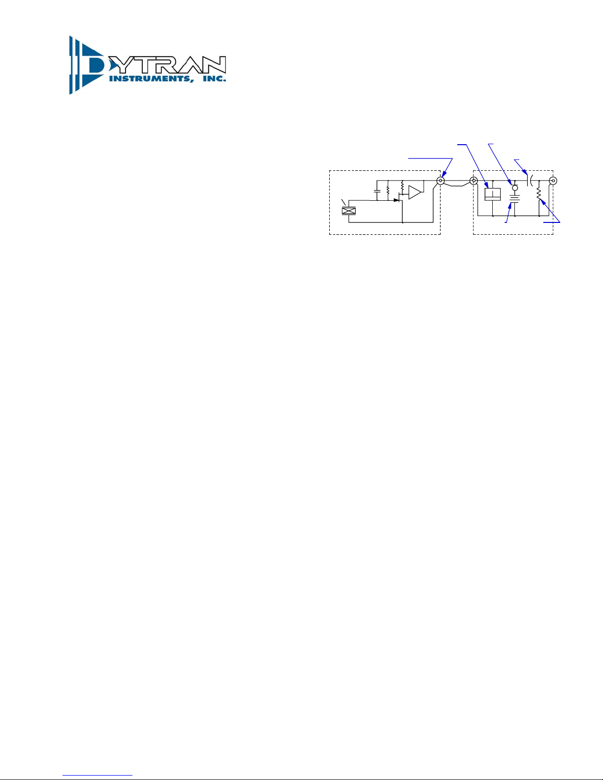
Because the IC is a 2-wire IEPE charge
amplifier, the dynamic output voltage signal is
impressed across the connector of the sensor which is
the same point into which the constant current from
the power unit is applied. (See Figure 1 below)
CURRENT
REG DIODE
DC POWER
SOURCE
POWER UNIT
COUPLING
CAP
+
PULLDOWN
RESISTOR
PIEZO
CERAMIC
SEISMIC
ELEMENT
C
f
FET INPUT
STAGE
MINIATURE CHARGE AMPLIFIER
SENSOR SERIES 3055B
SENSOR
CONNECTOR
R
f -
BIAS MONITOR
METER
HIGH
GAIN
STAGE
CABLE
Figure 1-Electro-mechanical schematic,
accelerometer and power unit system.
When constant current from the IEPE power
unit is applied to the accelerometer amplifier input
terminal, the amplifier "turns on" at approx. +12 Volts
DC quiescent bias level. When the accelerometer
senses acceleration, the resultant signal is
superimposed upon this bias voltage.
In the power unit, in its simplest form, a
capacitor blocks the DC bias and allows the dynamic
signal voltage to be separated and brought out to an
"output" jack on the power unit. At this point the signal
may be connected directly to almost any type of
readout instrument such as DVM's, oscilloscopes,
data collectors, spectrum analyzers, etc. The low
output impedance of the signal allows the driving of
long cables without adverse effects on sensitivity or
frequency response.
4
Page 5

Referring to Figure 1, the feedback resistor Rf
in conjunction with shunt capacitance Cf, forms a first
order high-pass filter which sets the low frequency
response of the accelerometer in accordance with the
following equation:
.16
f
RC
where:
f
R = resistance value R (Ohms)
C = total shunt capacitance C (Farads)
RC = discharge time constant TC (Seconds)
Equation 1 above, defines the frequency at
which the accelerometer sensitivity will be 3db down
when compared to the reference sensitivity measured
at 100 Hz.
The discharge time constant for all Models is
0.5 seconds, yielding a lower -3db frequency of 0.3
Hz, from equation 1.
As rule of thumb, the lower -5% frequency is
three times the -3db frequency or 1 Hz.
INSTALLATION
(Refer to Outline/Installation drawing 1273049E) To install Model 3049E series accelerometers,
it is necessary to prepare (or find) a flat mounting area
of approximately 0.5 inch diameter. Ideally, the
mounting surface should be flat to .001 in. TIR. The
flat mounting surface ensures intimate contact
between accelerometer base and mounting surface for
best high frequency transmissibility, thus accuracy.
3049E3, clean the mounting surfaces with solvent if
necessary to remove all traces of oils and other
impurities including burrs or any matter which could
preclude intimate contact between mating surfaces.
Apply a light coating of cynoacrylate adhesive
(or other type of suitable adhesive) to either mounting
surface, position the accelerometer in the desired
cable orientation and press the accelerometer firmly
= ------------------ (eq.1)
-3db
= lower -3db frequency (Hz)
-3db
To install the adhesive mounted 3049E1 or
onto the mounting surface and hold for several
seconds.
To install the stud mounted 3049E or 3049E2
accelerometers, drill and tap a 10-32 mounting hole
with enough thread depth to accommodate the integral
stud. Clean the area to remove all traces of machining
chips, burrs, etc. Spread a light coating of silicone
grease, or other lubricant, on either of the mating
surfaces and thread the accelerometer/stud
combination into the tapped hole by hand, until the
accelerometer base seats against the mounting
surface. Check to see that the mating surfaces are
meeting properly, i.e., that they are meeting flush and
that there is not an angle formed between the two
surfaces indicating that they are not co-planar. If this
condition is observed, torquing the accelerometer
down will strain the base causing possible poor
frequency response and even erroneous reference
sensitivity. Inspect the perpendicularity of the tapped
hole. If the hand tight meeting between the two
surfaces is satisfactory, torque the 3049E or 3049E2
accelerometer to the mating surface with 15 to 20 lbinch of torque, preferably measuring the torque with a
torque wrench torquing on the hex surface only.
Proper torque will ensure the best high
frequency performance from the instrument as well as
repeatability of sensitivity when mounting and
remounting. Excessive torque could damage the
ground isolation base.
Connect the cable (typically Models 6010AXX
or 6011AXX) to the accelerometer snugging up the
threaded lock ring tightly by hand.
NOTE: Do not use a pliers or vise grips on the
knurled lock ring. This could damage the
connector of the 3049E Series and/or the
cable connector.
To avoid stressing the cables which could lead
to early failure, especially under larger excursions of
the test object, it is good practice to tie the cable down
to a fixed surface near the mounting area at a point
approximately one inch from the accelerometer.
If there is excessive motion between the
accelerometer and the nearest tie point, allow a strain
loop of cable to let relative motion occur without
stressing the cable.
5
Page 6

Connect the other end of the cable to the
"Sensor" jack of the Dytran power unit (Models 4102C,
4103C, 4110C, 4114B1, etc.) and switch the power
on.
Observe the monitor voltmeter located at the
front panel of each of the power units. If the meter
reads in the mid-scale region, (labeled "Normal"), this
tells you that the cables, accelerometer and power unit
are functioning normally and you should be able to
proceed with the measurement.
Check for shorts in the cables and connectors
if the meter reads in the "Short" region. Check for
open cables or connections if the meter reads in the
"Open" area. In this manner, the meter becomes a
trouble shooting tool for the measurement system.
HIGH FREQUENCY RESPONSE
All piezoelectric accelerometers are basically
rigid spring mass systems, i.e., second order systems
with essentially zero damping. As a result, these
instruments will exhibit a rising characteristic as the
resonance is approached. A filter incorporated into
Model 3049E Series compensates for this rise.
The frequency at which the sensitivity may
increase or decrease by 5% is approximately 10,000
Hz, the frequency to which the 3049E Series series is
calibrated. The accelerometer is usable above this
frequency but to use it above 10,000 Hz, it must be
calibrated at the specific frequencies of intended use
because sensitivity deviations will increase drastically
as you greatly exceed this high frequency calibration
limit. Consult the factory for special calibrations
required above 10kHz.
CAUTIONS
1) Do not store or use the 3049E Series above
250 degrees F. To do so can damage the IC amplifier.
2) Do not allow cables to vibrate unrestrained.
This will eventually destroy the cable and could lead to
system inaccuracies.
3) Avoid dropping or striking the
accelerometer, especially against rigid materials such
as concrete and metals. While Model 3049E Series is
protected against shock induced overloads, the very
high overloads induced by dropping can do permanent
damage to the IC amplifier or to the mechanical
structure of the accelerometer. This type of damage is
not covered by the warranty.
MAINTENANCE AND REPAIR
The welded construction of the series 3049E
Series precludes field repair.
Should the mounting surface become
distorted, nicked and otherwise distressed, it can be
redressed by CAREFULLY wiping on a new sheet of
400 grit emery paper on top of a clean surface plate
(3049E1 and 3049E3 only). We stress "carefully"
because if not done properly, this procedure can do
more harm than good. Press the surface firmly against
the paper and draw directly toward you in several
short precise strokes making sure that the surface
remains in full contact with the paper and does not
"rock". Rotate the accelerometer 90 degrees and
repeat the procedure. When you observe the bottom
surface it should appear perfectly flat with straight
marks across it. If you cannot achieve flatness with
several attempts, return the instrument to the factory
for repair.
Should the electrical connector become
contaminated with moisture, oil, grease, etc., the entire
instrument may be immersed in degreasing solvents to
remove the contaminants. After degreasing, place the
instrument in a 200°F to 250°F oven for one hour to
remove all traces of the solvent.
Should a problem be encountered with the
operation of the instrument, contact the factory for
trouble shooting advice. Often our service engineers
may point out something which may have been
overlooked and which may save the expense and time
of returning the 3049E Series to the factory.
If the instrument must be returned, the service
department will issue you a Returned Materials
Authorization (RMA) number to aid in tracking the
repair through the system. Do not send the instrument
back without first obtaining an RMA number. At this
time you will be advised of the preferred shipping
method.
A short note describing the problem, included
with the returned instrument, will aid in trouble
shooting at the factory and will be appreciated.
We will not proceed with a non-warranty repair
without first calling to notify you of the expected
charges. There is no charge for evaluation of the unit.
6
 Loading...