

Page 1

D y n a m i c T r a n s d u c e r s a n d S y s t e m s
2 1 5 9 2 M a r i l la St. • Chat s w o r t h , C A 9 1 3 1 1 • P hone 8 1 8 -700-7818
w w w . d y t r a n . c o m • e -mai l : i n f o @ d y tr an.com
OG1060C.docx 1-25-01
OG1060C.docx ECN 9708 3-6-13
Rev B, ECN 12920 08-23-16
OPERATING GUIDE
MODEL 1060C
CHARGE MODE DYNAMIC FORCE SENSOR
This manual contains:
1) Outline/Installation drawing 127-1060C
2) Operating Instructions Model 1060C
Page 2
2
OPERATING INSTRUCTIONS MODEL 1060C
PLATEN
QUARTZPLATE
AND INSULATOR
10-32COA XIAL
CONNECTOR
THREADED
MOU NTING STEM
CHARGE MODE DYNAMIC FORCE SENSOR
INTRODUCTION
The 1060C force sensor is designed to
measure compressive and tensile forces over a
wide dynamic range, e.g., from 10 Lbs full scale to
25,000 Lbs full scale over a very wide frequency
range, (quasi static to 50 kHz.) This sensor can
measure to 500 Lbs full scale in tension.
A thin x-cut quartz crystal held under very
high preload, provides an electrostatic charge output
analogous to dynamic force input. The output
polarity is negative-going for compression and
positive-going for tension.
Model 1060C features an integral axial
mounting stud (threaded stem) which protrudes from
the bottom of the unit. The 10-32 coaxial electrical
connector is at the end of this stud.
DESCRIPTION
Refer to figure 1 below for a representative
cross section of Model Series 1060C force sensor.
Series 1060C features an integral threaded
(11/16-12 thread) mounting stud for convenient
mounting where radial space is limited. As
previously stated, the electrical connector is located
at the bottom end of the stud.
Referring to Figure 1, the upper threaded
member (called the platen) distributes the force
evenly across the quartz crystals while sealing the
instrument against moisture and other contaminants.
The very thin quartz crystal comprise a relatively
small portion of the length of the sensor which
results in a very high stiffness and high rigidity and
natural frequency. The overall stiffness of this
instrument is almost comparable to a solid piece of
steel of similar dimension.
Refer to the Outline/Installation drawing,
127-1060C, supplied with this manual, for a
dimensioned outline of Model 1060C.
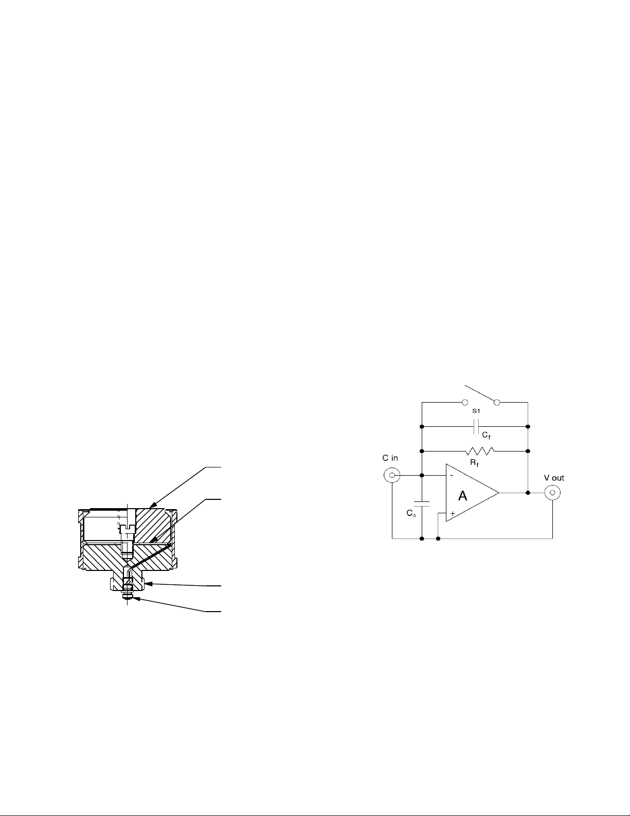
THEORY OF OPERATION
Force compressing the load cell stresses the
crystals causing an electrostatic charge to be
generated which is exactly analogous to the applied
force. A special type of amplifier called a Charge
Amplifier because of its high impedance level must
read out this charge. Refer to Figure 2 below.
Figure 2: THE CHARGE AMPLIFIER
(SIMPLIFIED SCHEMATIC)
A charge amplifier has the ability to read out
the very small signal from the force sensor without
Figure 1: CROSS SECTION, MODEL 1060C
Model 1060C is recommended for use
where radial space is limited such as in some drop
shock testers, in impact hammers or when
instrumenting shafts or pushrods where there is no
space around the machine for the electrical
connector to exit radially.
OG1060C, Rev B, ECN 12920 08-23-16
changing the signal. The charge amplifier converts
the charge mode signal generated by the crystals to
a low impedance voltage which may then be fed
directly to almost any type of readout instrument.
A charge amplifier is essentially a very high
input impedance-inverting amplifier with infinite gain
and with capacitive feedback. It can be shown that
as the gain of the amplifier (-A) approaches infinity,
the transfer function of the charge amplifier
becomes:
Page 3

3
-q
Vo = -------- (Eq 1)
Cf
Where:
Vo is the output voltage (Volts)
q is the input charge, (pC)
Cf is the feedback capacitor, (pF)
This means that the sensitivity of the charge
amplifier is determined by the value of the feedback
capacitor only. Since the output voltage is fed back
to the summing junction of the amplifier (the input
terminal) the virtual input impedance is extremely
high which means that the charge signal generated
by the quartz crystals will not be drained away by
the measuring device.
SIGNAL POLARITY
Compressive forces on these sensors (see
Figure 1) produce negative-going output signals.
This is because most charge amplifiers are inverting
amplifiers and the output signal from the charge
amplifier will be positive going for compressive
loads. This is conventional.
By the same token, tension loads on the
1060C will produce positive-going output signals.
SENSITIVITY
The nominal charge sensitivity of Model
1060C is -9 pC/Lb.
CHARGE AMPLIFIER SELECTION
Dytran manufactures many different types of
charge amplifiers to suit the needs of most any
measurement requirement from the larger laboratory
type Model 4165 which features ranging and filtering
plus standardization to the miniature in-line types
4751 and 4705 which adapt the 1060C to LIVM
operation with constant current power units. For
laboratory measurements, the 4165 is
recommended and for field use, the dedicated
sensitivity in-line charge amplifiers may be a better
choice.
Consult the factory for recommendations on
the best type of charge amplifier for your
measurement needs.
INSTALLATION
Refer to outline/installation drawing 127-
1060C, supplied with this guide.
To mount model 1060C, it is necessary to
prepare a flat smooth mounting surface of 5/8”
minimum diameter. The surface should be flat to
.0005 TIR for best results.
The mounting port must provide for room to
connect the cable to the 10-32 connector at the end
of the threaded integral mounting stem. Drill and tap
a thru hole to accept the 11/16-12 thread on the
mounting stud to secure the 1060C to its mounting
surface.
Before mounting the 1060C, thread the
sensor into the mounting port and examine the fit of
the mounting surfaces. They must meet parallel, i.e.,
a wedge must not be formed between these
surfaces. Also, at this time, inspect the mating
surfaces for foreign particles which may become
lodged between these surfaces and clean if
necessary. It is important that the mating surfaces
meet squarely and intimately with no particles of
foreign matter of any kind included between them.
Foreign particles included between mating surfaces
could damage the sensor and/or modify the
sensitivity of the sensor.
When you are satisfied that the surfaces are
square and clean, place a thin layer of silicone
grease on one of the surfaces and thread the force
sensor place, torquing it in place with 25 to 30 Lbinches of torque to secure.
For most impact applications, the Model
6217 (steel) impact cap will be utilized. This cap is
threaded into the platen (top surface of the force
sensor). Thread this cap securely into the tapped
hole in the platen, again inspecting for foreign
particles between mating surfaces and clean if
necessary. For more permanent installations,
thread-locking compounds may be used to secure
the installation. Use these compounds sparingly.
For a slightly higher resonant frequency, an
aluminum version of the 6217 may be a better
choice in some applications. Consult the factory for
availability and price for various other materials
which may better suit your measurement needs.
Connect the sensor to the charge amplifier
using Series 6010AXX cable (10-32 to 10-32) or
Series 6011AXX (10-32 to BNC plug), depending on
the connector called for by the power unit. Tighten
the cable lock ring snugly by hand. Do not use a
pliers or vise grips on these cable lock rings.
OG1060C, Rev B, ECN 12920 08-23-16
Page 4

4
OPERATION
MODEL
1060C
F
PROPER TENSILE
LOADING USING
THREADED HOOK EYES
After connecting the cable from the sensor
to the charge amplifier, if the charge amplifier is the
laboratory type, press the reset button which should
zero the output voltage. You are now ready to select
your range, set the discharge time constant and
make the measurement.
If you are using an in-line charge amplifier,
there is no reset button so you must wait a few
seconds for the output voltage to stabilize. The
instrument may be used before complete
stabilization of the sensor bias voltage since the DC
bias is blocked within the power unit.
Consult the factory for the low frequency
limitations and other limitations when using the inline charge amplifiers.
LOADING CONSIDERATIONS, IMPACT
When applying loads to the force sensor, it
is important to note that the load must be distributed
evenly across the force sensitive face of the force
sensor.
For impact measurements, the impact cap
accomplishes this adequately in most cases. During
impact testing, try to control the impact point so the
contact occurs close to the center of the sensor. For
more massive objects impacting the sensor, a
special thicker cap may need to be employed.
Consult the factory for special applications such as
this.
Figure 3 is intended to illustrate the right and
the wrong way to apply loads to the 1060C.
Obviously we cannot address all of he many
different applications that may arise but we want to
illustrate, in the most basic sense, the proper and
improper ways to apply loads to these instruments
for the purpose of heading off measurement
problems which may be incurred by improper use.
In the illustration chosen in Figure 3, the
force sensor is being loaded dynamically by a
hydraulic or pneumatic ram. It is important that the
force be evenly distributed, centrally, to the force
sensor and the right way would be to use a steel ball
to evenly load the sensor through a special adaptor
which has been designed to center the ball over the
force sensor.
Dytran offers such adaptors as a special
order accessory. Our engineering department and
our state of the art machine shop are at your
disposal for the design and fabrication of such
adaptors. Call the factory for assistance with your
particular measurement problem.
TENSILE LOADING
Figure 4 (following) illustrates one proper
way to load the 1060C in tension. Again, the forces
must travel through the center of the sensor.
FIGURE 4
PROPER TENSILE LOADING
FIGURE 3
ILLUSTRATING OFF-CENTER LOADING
OG1060C, Rev B, ECN 12920 08-23-16
The arrangement shown in Figure 4 ensures
that the load is applied centrally to the sensor
without bending moments and transverse loading.
One important point to keep in mind when
making tensile measurements is that, due to limits in
the design of the internal preload structure of these
Page 5

5
sensors, the maximum tensile force is limited to
1000 Lbs. in this series. If this level is exceeded,
the sensor may be destroyed and the load could
be suddenly released. This could engender
dangerous situations for personnel and equipment if
this eventuality is not fully understood.
Remember that the maximum force is the
combination of both static and dynamic tensile
forces. For example, if the sensor is supporting a
static load of 500 Lbs., the maximum dynamic range
possible is 500 Lbs, (1000 - 500).
QUASI-STATIC CONSIDERATIONS
Close to DC measurements are possible
with the 1060C when used with a laboratory type
charge amplifier such as the model 4165. These
force sensors are calibrated at the factory by placing
a traceable compressive force on them, (with a
proving ring) then rapidly removing it and capturing
the resultant step function on a digital storage
oscilloscope. This is a very accurate and repeatable
method for calibration of these sensors.
MAINTENANCE AND REPAIR
The sealed construction of model 1060C
precludes field maintenance. Should you experience
a problem with your sensor, contact the factory to
discuss the problem with one of our sales engineers.
If the instrument must be returned to the factory, you
will be issued a Returned Materials Authorization
(RMA) number so we may better follow the
instrument through the evaluation process. Please
do not return an instrument without first obtaining the
RMA number. There is no charge for the evaluation
and you will be notified of any charges before we
proceed with a repair.
OG1060C, Rev B, ECN 12920 08-23-16
 Loading...