

Dyson XYS10013 Installation & Assembly
300mm minimum
200mm maximum
385mm minimum
200mm maximum
200mm maximum
PRE-INSTALLATION INFORMATION
Sink specification guidelines
Using a specially designed test method, Dyson engineers
tested a wide range of sinks to assess their compatibility with
the Dyson Airblade Wash+Dry hand dryer. For recommended
sinks, please use our guide at www.dyson.com/docs
Porcelain or brushed metal sinks are ideal.
Sinks with highly polished surfaces should be avoided
e.g. reflective chrome.
Fi g.1
15” (380 mm) minim um
350mm minimum
13” (330 mm) minimum
Faucet mounting
The faucet stem (measured from the outside diameter) should
be mounted
1
/2” - 1 1/2” (15-40 mm) from the outside edge of
the sink.
There should be a minimum of 11
1
/2” (290 mm) between a
faucet center and a side wall. When multiple faucets are installed
side-by-side, faucet centers should be a minimum of 22
7
/8”
(580 mm) apart. This allows sufficient space for mounting
the motor bucket, as well as sufficient shoulder room for users.
Fig.2
maximum
8” (200 mm)
Fig.3
16 3/16” (411 mm) minimum
minimum
5” (127 mm)
100mm minimum
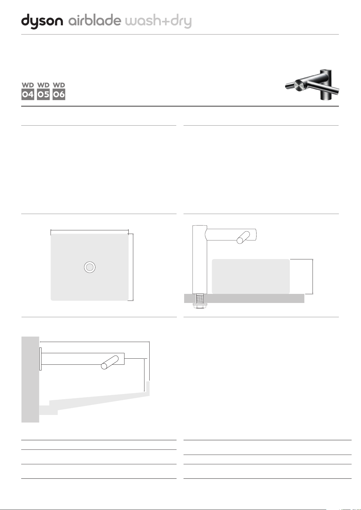
Sink dimensions (All internal measurements unless other wise stated)
Fi g.1 Width of sink minimum: 15” (380 mm),
Front to back of sink minimum: 13” (330 mm)
Fig.2 Maximum depth of sink for Tall Neck Faucet ( WD05) only: 8” (200 mm)
(External measurement of vessel/pedestal sink.)
Fig.3 Minimum distance from faucet center to top of sink (WD06 only) 5” (127 mm).
Front edge of sink (all types – pedestal, recessed, slab) to wall minimum 16
Internal depth of sink minimum (for all models): 5” (127 mm)
3
/16” (411 mm).
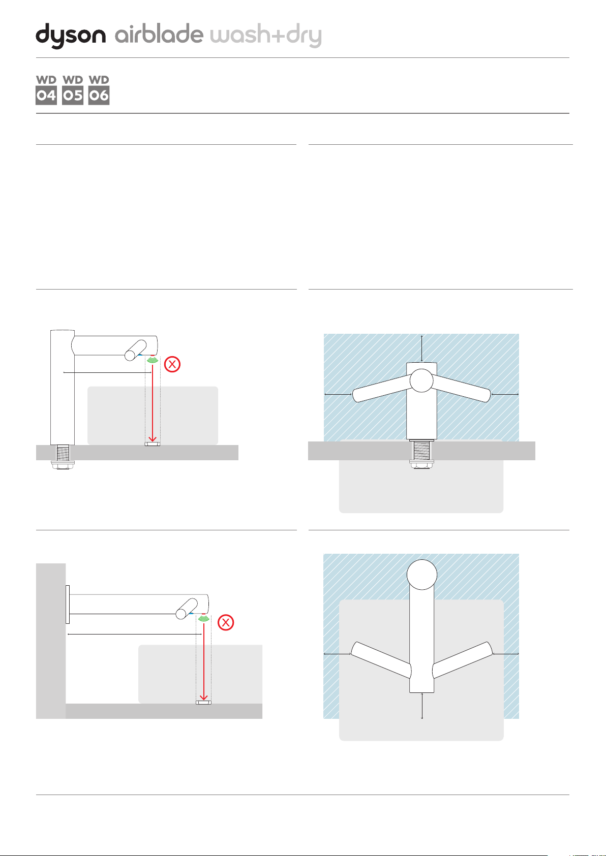
Faucet mounting
Soap and locating the soap dispenser
Do not place the downward facing water sensor of the faucet
over a reflective surface, such as the drainage hole. (Fig.4)
For complete instructions, please refer to the printed
installation guide supplied with the machine.
It’s also available online at www.dyson.com/docs
Fig.4
WD04, WD05
9 7/16” (240 mm)
For best user experience, Dyson recommends the use of gel soaps.
The infrared sensing zone for air activation extends along each
faucet branch. In order to prevent accidental activation, it’s
important to consider the user’s hand route to the soap dispenser.
The dispenser should be located at least 2
5
/16” (60 mm) outside the
width of the faucet, so the user reaches around the side of the branch.
It should also be located at least 2
5
/16” (60 mm) above the
branches, so that the sensors are not activated.
Please note that the user may reach diagonally across for the soap,
so this path must not go through the sensing zone.
Front on view showing
soap dispenser
clear zone
2 5/16”
(60 mm)
”
16
/
5
2
(60 mm)
2 5/16”
(60 mm)
13
11
/16” (300 mm)
WD06
Over head view showing
soap dispenser
clear zone
5
2
/16”
(60 mm)
2 5/16”
(60 mm)
”
16
/
5
2
(60 mm)
 Loading...