

Page 1
Page 2
Quick Start Guide
What’s included:
· Dyno S1 preinstalled in an OEM crankset.
· Dyno S1 USB adapter (micro or mini)
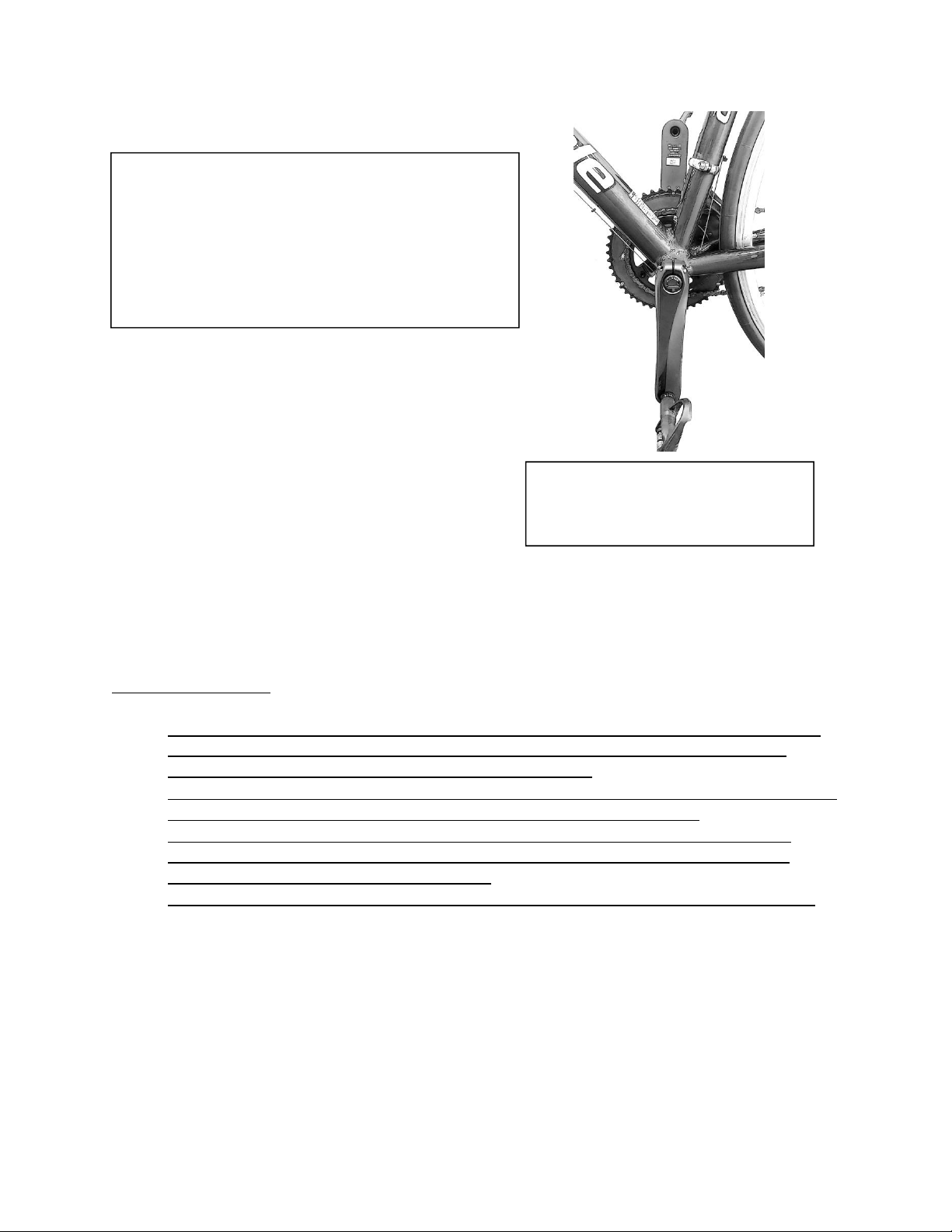
Figure 1. Non-Chain Arm in the 6
o’clock position. Always use this
position for the zero offset calibration
IMPORTANT NOTICES:
· The Dyno S1 USB adapter is ONLY used for charging/communicating. Do NOT use to tighten or
loosen Dyno S1 Cap as this could cause the adapter to break. Care should be taken when
connecting and/or disconnecting the adapter to the Dyno S1.
· Should the crankset installation require removal and reinstallation of the Dyno S1 electronics for
crankset installation, use a spanning wrench (Park Tool SPA-6 or equivalent).
· When removing a crankset having a Dyno S1, NEVER hammer on the cap as this will cause
damage to cap and electronics. Follow ‘Installing/Removal of the Crankset’ procedure for
removing and installing the electronic module.
· Always use a 2.0 USB Hub and never a 3.0 USB Hub for communicating/charging the Dyno S1.
Please follow the following steps to start riding with power. Do not install the crankset until first
confirming communication by using the Dyno Calibration Wizard.
What you will need:
· USB 2.0 –Mini or Micro B USB to Type A USB cable depending on the Dyno S1 USB Adapter
shipped with the power meter. Cable length shall not exceed 3 meters.
· Windows PC for the Dyno Calibration Wizard
Page 3

· Internet Connection
· ANT+ Display unit (Cycle computer with Power) such as an Garmin Edge 510 or equivalent.
· Park Tool SPA-6 or equivalent spanner wrench
Warning:
To reduce the risk of injury to persons and damage to the Dyno S1:
· Do not submerge the Dyno S1 in water if not installed in a crankset as there is no water
protection.
· Do not reach for an uninstalled Dyno S1 that has accidentally fallen into water or other liquid.
· If an uninstalled/ installed Dyno S1 is damaged, do not attempt to charge the battery.
· Other than use in a power meter, Dyno Velo is not responsible or liable for any other uses of
this product.
· Use only a Dyno Velo rechargeable battery.
· Use only USB 2.0 computer ports.
Battery Warning and Environmental Notice:
If these guidelines are not followed, the internal lithium ion battery may experience a shortened life
span or may present risk of damage to the device or personal injury. Dispose of a spent or a damaged
battery according to local laws and regulations.
· Do not use sharp objects, or an electrically conductive object (such as a small metal screwdriver)
to remove the battery.
· Keep the battery away from children or pets.
· Do not disassemble, puncture, or damage the battery.
· Do not expose the battery to extreme temperatures less -20C and greater than 60C
· Do not charge the battery at temperatures less than 0C or greater than 45C
· Do not long term store batteries at less than -20C or greater than +25C.
· If using an external battery charger, use the Dyno S1 USB adapter.
· Only replace the battery with the correct replacement battery.
· Stop using the battery if abnormal heat, odor, discoloration, deformation, or abnormal
condition detected during use, charge, or storage.
· If liquid leaks onto your skin or clothes, wash well with fresh water immediately.
· If liquid leaking from a battery gets into your eyes, do not rub your eyes. Wash them well with
clean edible oil and go see a doctor immediately.
Water Resistance Notice
Properly installed the Dyno S1 has a water ingress protection of lPX7 (up to 1 meter). This will permit
water protection for normal cycling conditions either on-road or off-road. The cap’s USB cover is for
water splash and dust/dirt protection. Replacement dust covers can be replaced by the user using a T3
driver. In the event of a lost/torn dust cover, a piece of electrical tap covering the USB adapter pins will
provide adequate dust protection.
Page 4

Do not subject the power meter to direct spray from a high pressure sprayer. There is high probability
that water will be forced past the O-ring seals, and under these conditions, damage to the electronics
may occur. Should the Dyno S1 be accidentally subjected to a high pressure water spray, the power
meter should be immediately serviced to avoid potential damage from water. Should the external
USB electrical pins ever require cleaning, a soft toothbrush may be used.
Power Meter (Crankset) Installation
Follow the 10 steps below to getting the power meter up and working with your display.
1. Install the Dyno Calibration Wizard which can be found at www.dynovelo.com/downloads. You
will need the Dyno Calibration Wizard in order to unlock the Dyno S1 power meter. The Dyno S1
is locked in order to keep the power meter from transmitting during shipment. When first
connecting to the Wizard, the Dyno S1 will automatically be unlocked.
2. Connect the Dyno S1 to a USB 2.0 hub on your PC using the Dyno S1 USB adapter with a USB
cable. Do not connect to a USB 3.0 hub (damage to your computer or the Dyno S1 could occur if
your USB cable has a short). Your PC will recognize a new device and install drivers
automatically.
3. Unlock the Dyno S1 power meter. Launch the Dyno Calibration Wizard. The Wizard will
recognize your Dyno S1 and automatically unlock it.
4. Retrieve your ANT+ ID. This number is unique to your torque sensor.
5. Charge the battery. Leave the Dyno S1 connected to your PC (or after Step 4, attach to an
external USB 2.0 not exceeding 5V) and let it fully charge the battery. Either terminate charging
after 2 hours or when the red light turns off. See Battery Charging and Indicator Lights below.
6. Install the crankset following the manufacturer’s procedure.
7. Pair the Power Meter. After installing the crankset, follow the ANT+ display unit instructions
(See Pairing the Power Meter below) and pair the display to the Dyno S1 (connecting wirelessly
to the Dyno S1) using the ANT+ ID obtained during Step 4. Always manually enter this number
into the ANT+ display if the display does not automatically find the Dyno S1. NOTE: When the
Dyno S1 is connected to the Dyno Calibration Wizard, no wireless communication is possible.
Prior to rotating the crankset, the USB adapter shall always be disconnected from the Dyno S1 at
the crankset. To turn on the power meter, the crankset must be rotated from the non-chain
side at 40 rpm or higher and for longer than 1 second.
8. Perform a Zero Offset Calibration. See further instructions below. A Dyno S1 that is preinstalled
in a crankset is already pre-calibrated at the factory but will always require a zero offset
calibration (or setting the zero when no load is applied).
9. Perform a Dynamic Zero Balancing. The power meter is at this point is ready and operating. To
achieve proper results a Dynamic Zero Balancing is required. See further instructions below.
10. Break in the Power Meter. Since the sensing technology is frictionally engaged which allows the
sensor to be removable, the power meter needs to be broken in before the wattage reading will
stabilize. Hill riding and hard sprints will vastly accelerate the break in period. This process is
known as Brinnelling the metal, and though not the same is akin to packing down fresh dirt until
the dirt no longer packs down.
Page 5

Battery Charging and Indicator Lights
Ensure the power meter is fully charged. For a fully charged battery, the riding time is 20+hours. The
Dyno Calibration Wizard has both a temperature monitor and a battery voltage monitor. A fully charged
battery registers at over ~4.0+ V. A discharged battery is ~3.45 V. The charge cycle is set for two hours
to prolong the life of the battery. The battery can be charged over 400+ times under normal conditions,
but will vary with usage and storage. The blue light is always illuminated when USB power is present.
The red light will remain illuminated while the battery is being charged. The red light will go out upon
the battery being fully charged. In rare cases the red light may not go out after the preset two hour time
limit. Do not be alarmed if this occurs. However, a flashing red light may indicates a faulty charging
circuit or battery. If this occurs, disconnect the USB adapter and reconnect, if the red light proceeds to
flash again after a period of time contact support. If a battery is NOT present and the USB is plugged in,
only the blue light will be illuminated. In addition, the Dyno Calibration Wizard will not be able to detect
if the battery is not present, and the voltage reading will not be accurate. If a battery is connected and
the red light does not illuminate, this may indicate an issue with either the battery, the USB adapter
itself, or the USB connection. The most common problem is a connection issue with the USB adapter.
When unplugging the USB and reconnecting the USB, the charge cycle starts all over again, and the red
light may stay on for some time. In general the Wizard does a very good job of reading the battery
voltage. For further trouble shooting see Dyno Velo’s website.
Installing/ Removal of the Crankset
When removing a crankset with a Dyno S1 NEVER hammer on the cap of the Dyno S1 as this will
damage the power meter. Follow the Installing/Removal of the Crankset procedure for removal and
installing the electronic module.
In most installation cases, the non-chain crank arm spindle bearing-crank arm gap can be set by pushing
on the crank arm If, the crank arm needs to be tightened to set this gap, the Dyno S1 modular
electronics can be removed and reinstalled. The Dyno S1 cap uses a right-hand thread, thus unscrew by
turning counter clockwise. Only 3 turns are needed to tighten or loosen the cap. Avoid excessively
twisting the connector wiring harness, and when removing, be careful to avoid snagging the harnessing
wires. Always use a spanner wrench for cap removal and protect the crank arm from potential
scratches. Prior to disconnecting the wiring harness, first, disconnect the battery by gently pulling on all
three wires of the battery connection. Disconnect the wiring harness by pushing directly down on the
connector tab directly above the harness wires while pulling out the harness connector. The harness
connector can now be pushed back into the spindle allowing for normal installation of the crank arm.
After tightening the crank arm, remove the crank arm side adjuster and reinstall the Dyno S1 electronics
by the reverse order of connecting the wiring harness connector first, making sure that the harness
connector snaps into place, gently tugging on the wiring harness to confirm, and then reconnecting the
battery connection. A broken/dulled toothpick works well for the battery connector. Note for battery
wires that the red wire is towards the cap, black wire towards the PCB header pins.
Page 6

Pairing the Power Meter
The power meter must be connected or “paired” to the cycle computer (display) according to the
display manufacturer’s instruction. Follow the ANT+ display manufacturer’s instructions for pairing a
power meter. Since each power meter has a unique ANT+ device ID, the display has to either find this
wireless, or the ANT+ID must be manually entered. During the pairing process the ‘ANT+ID’ will be used
to communicate with the corresponding power meter. The ANT+ ID number can be obtained using the
Dyno Calibration Wizard (Step 4 above) and is also located on the chain side crank arm. Once paired to
the power meter, both Watts and RPM (Cadence) will be transmitted from the power meter to the
display unit, provided the power meter is in operation. NOTE: The ANT+ ID is permanently assigned to
the power meter sensor and is not affected by changing either the power meter battery or by
upgrading the electronic module.
Zero Offset Calibration
Please note that some device manufacturers refer to the step of resetting the zero offset as just
“calibration” so keep this in mind as this can be confusing. Calibrating the zero offset is a function
controlled by the cycle computer (display unit) when paired to the Dyno S1 power meter. When paired
to a compatible ANT+ display unit, the power meter and display unit are in two-way communication.
Although the process for calibrating the zero offset will vary depending on the display manufacturer, it
should roughly follow these general steps; however consult your display unit’s manual for specific
instructions:
1. Ensure the power meter has been paired to and is communicating with the display unit.
2. Position the crank straight down (6 o’clock position) and make sure the bike is stable.
3. Access the settings function of the wireless display.
4. Select the power sensor (many times the power sensor is located within a “BIKE” setting).
5. Select the “CALIBRATE” or “Zero” function.
6. Calibration of the zero offset will begin and take only a few seconds*to complete. (*see
Calibration time out)
7. Upon completion the display will show a message indicating success or failure of the procedure.
Please note the displayed zero offset value will likely NOT be zero. The Dyno S1 sends back a number
that is in ‘Watts’ by which the sensor is offset at 60 rpm. This number also includes the temperature
change as well, and thus is not a true wattage error as the temperature is automatically compensated
but is included in this number. Large offset numbers indicate that a high temperature value may have
caused a shift, or the break in periods is not over, or if wattage numbers are appearing incorrect that the
sensor has come loose. Temperature, drift, aging and other variables affect the zero offset value. The
Dyno S1 will automatically temperature compensate, but works in conjunction with the zero offset
calibration, and thus the zero offset calibration also records the temperature at which automatic
temperature is being adjusted about. For a better understanding of this please see the Dyno Velo
website.
The non-chain crank arm shall be located in vertical position with its pedal located closest to the ground
(6 o’clock). See Figure 1. Note that the Dyno S1 must be awake for wireless zero offset calibration. To
wake the unit, the crankset must be rotated from the non-chain side at 40 rpm or higher and for longer
than 1 second, alternatively a soft start turns on the Dyno S1. A soft start is when the USB adapter is
Page 7

plugged in and power comes from a USB 2.0 on the computer or from an AC-DC 5V charger, and then
unplugged from the Dyno S1. As long as a battery is present and has sufficient charge, the Dyno S1 will
at minimum stay awake for 2 minutes without the non-chain crank arm needing to be rotated. The
Dyno S1 also allows the zero offset to be set by using the Dyno Calibration Wizard. Note: if the Dyno
Calibration Wizard is used for the zero offset calibration, be sure to use Figure 1 at the 6 o’clock position
and not to place the crank arm in a horizontal position as this position is only ever used for calibrating
the maximum output (Sensor Output/Weight to slope).
The zero offset is the sensor reading when there is no pedaling load (torque) applied. For accurate
power measurement readings, the sensor reading when no load is applied to the sensor is needed. This
value is stored in sensor memory. Unplugging the battery will not lose this reading in sensor memory.
When the crank is at the 6 o’clock position there is little to no torque to the sensor. The sensor output
at this position needs to be recorded, and this is known as the ‘zero offset’. This value is used by the
power meter to determine the correct power in Watts.
Ambient temperature changes will affect the zero offset. To ensure maximum accuracy, manually
calibrate the zero offset before each ride, and do not perform zero offset calibration unless the power
meter is at a stable temperature. The power meter utilizes temperature sensors to automatically
compensate for temperature changes that take place during the ride based on the temperature at which
zero offset calibration is performed. Thus, even if your unit has been zero calibrated that day, it is
highly advisable to do a zero offset calibration if your power meter has undergone a large temperature
change whether cold or hot. The crankset itself (not the sensor) can take over a half hour to
temperature stabilize. The Dyno Wizard Calibration has a temperature monitor that displays the sensors
temperature. This temperature monitor can also be used by the user to verify and check how long the
crank and bike take to temperature stabilize (USB adapter needs to be left in. See Dyno Velos website
for further information. Temperature calibration is done automatically while you ride after you zero
offset calibrate and you need not take any further steps to calibrate the sensor during the ride.
Calibration time out
When using a Garmin display unit with a heart rate (HR) sensor enabled, it is possible the calibration
process will take too long and time out before completion. To resolve this, either turn off the HR sensor
on your Garmin while you calibrate your power meter (you can turn it back on once the power meter is
calibrated) or put the HR strap on and ensure it has been detected by the display before you attempt to
calibrate the zero offset.
Dynamic Zero Balancing
Similar to a new car tire needing to be balanced, the Dyno S1 also needs balanced. For much more
information refer to the website. Follow these quick instructions:
1. Set the non-chain crank arm in the zero offset calibration position (6 o’clock) and connect to the
Dyno Calibration Wizard. Go to the third page (step 6) ignoring the crank positional picture) and
mouse click on ‘Set Zero’.
Page 8

2. Return to second page where weight is displayed in lbs/kgs, and confirm crank position and that
the weight is near zero (will display +/-0.00x fluctuating a small amount).
3. Select Calibration>Properties and at the upper right check the ‘Enable Manual Mode’ radio box.
4. At the left bottom of screen is Dynamic Offset. Go to Step 1 of this box and Mouse Click once on
set. Hit okay when asking to proceed. Close property page by hitting ok on the right bottom of
the page. Weight will be ~2.04lbs/.925kg. If not, return to Step 1.
5. Disconnect the USB adapter at the crankset. You will be spinning the crank next. Do not spin the
crank if the USB adapter is installed at the crankset.
6. Using your display’s stop watch/time feature (where you start and stop a ride), set your power
meter display page to show these two fields: the average power (Avg. Pwr.) and average
cadence (Avg. Cad.).
7. With the bike elevated, or in a training stand (no resistance is needed), spin the CHAIN –SIDE
crank arm (do not spin from the non chain side crank arm) and bring the crankset up to an
elevated rpm (higher the better) and start/stop for at least 1 minute.
8. Set the non-chain crank arm in the zero offset calibration position (6 o’clock). Connect to the
Dyno Calibration Wizard.
9. Select Calibration>Properties; and at the upper right of the window, check the ‘Enable Manual
Mode’ radio box.
10. Return to the Dynamic Offset Box (lower left of the window), and go to Step 2 in this box and
type in the Average Cadence (RPM) and Average Watts (Power) which were recorded from Step
7 of this procedure, being sure to enter the proper value in the correct box.
11. Make sure the NON-CHAIN Crank arm is at the 6 o’clock positon. Mouse click on ‘Calculate’. Hit
‘ok’ on the next page. Close the window.
12. Confirm the weight is reading zero on page 2 of the Wizard.
13. Confirm power meter is properly working by spinning the Chainside crank arm. One should see
that only 0- 1 of power is displayed. (The Dyno S1 only displays power from the non-chain side
crank arm).
14. Switch to the Non-chain crank arm and spin it. One should see a low wattage.
Troubleshooting
The Dyno S1 can be trouble shot very easily using the Dyno Calibration Wizard program.
If no power (watts) or cadence (RPM) reading is being received by your display when riding the bike,
please confirm the following items:
1. Confirm that the battery is charged and is properly installed. Check the voltage using the Dyno
Calibration wizard.
2. Confirm using the Dyno Calibration Wizard that the sensor is displaying and updating the mV
and weight display outputs. If not, disconnect the USB and reconnect the USB and check again.
3. Using the Dyno Calibration Wizard menu, select Calibration >Properties and verify that sensor
data, electronic location, crank length and Weight Slope are not zero. Note that if your Dyno
S1 does not seem to work when just turning the non-chain crank arm with your finger, but
seems to work when in a bike resistance trainer, or on the road, then the Dynamic Zero
Balancing is likely needing to be set or corrected. See the Dyno Velo website for further
information on how to set this parameter. Likely, the wattage is incorrectly less than zero due
to an improper dynamic zero balance, and thus is not reporting to your display until positive
Page 9

wattage from a higher load is seen. Thus your Dyno S1 is not sending cadence or wattage to the
display as the Dynamic Zero Balance is negative.
4. Confirm your display is paired to your Dyno S1 and not another power meter or even another
Dyno S1.
5. For further assistance with Troubleshooting, FAQS, videos and useful tips, please visit our
website at: www.dynovelo.com/support.
Firmware
Firmware is the programming that operates the power meter’s computer. The power meter has been
designed to allow new firmware to be loaded using the Dyno Calibration Wizard. Updated firmware
may be developed and released by Dyno Velo to provide added or improved functionality.
The latest firmware will be available through the Dyno Velo Website along with instructions on how to
update the power meter.
Maintenance and Cleaning
The Dyno Velo was designed for both the professional and the home mechanic. As such, trouble
shooting; calibrating; removal and re-installing in another crank are all possible (all new calibration are
are required including a new sensor output/weight slope value). Items that can be serviced are the Orings and seals, and even replacement of the electronics cover. Items such as the electronics and the
sensor are separately replaceable, but were not designed to be serviced. No other items are
serviceable and no attempt should be made to adjust or to alter any other item.
The power meter uses a custom seal for the cap to electronic interface. All other O-rings are standard
metric Buna-N rubber O-rings. Silicon grease or equivalent may be used to seal your Dyno S1. Grease
shall always be used with the O-rings. The grease protects the O-ring from abrasions, environmental
conditions and is critical to ensure proper water resistance. When servicing the O-ring ensure it is well
coated with a grease designed for use on O-rings which may be obtained at most hardware stores.
When cleaning the power meter use only a water dampened cloth to wipe off dirt and debris (external
components only), and a very soft toothbrush. Never use any harsh cleaning chemicals that may
damage the plastic housing. Inspect the USB connector and pins ensure the contacts are free of any
corrosion. In the event of corrosion, the electronics can be removed and reinserted using a T5 driver,
which allows the connector pins to be thoroughly cleaned. A new USB connector pin seal should always
be used when the electronics are disassembled and silicon used as well for sealing. Whenever working
on the Dyno S1 the battery shall always be removed.
Never directly spray the power meter with high pressure water. The water pressure from sprayers
can reach thousands of pounds per square inch and may force water past the O-ring damaging the
power meter electronics.
Warranty procedures
Page 10

Complete warranty details is available at our website FAQ page:
http://www.dynovelo.com/support
The Dyno S1 power meter is considered to be the electronic module, and the sensor, and as such are
limited to a one year warranty. As such customers are instructed to contact their retailer or Dyno Velo
directly for all warranty claims related to the power meter. Do not contact the crank manufacturer for
warranty concerns regarding the power meter.
To pursue a warranty claim please contact the retailer that sold the power meter. If the power meter
was purchased directly from Dyno Velo please contact us directly via the website.
In all cases a Return Authorization Number (RA#) must be issued by Dyno Velo before any product is
returned for warranty inspection and service.
The Dyno Velo power meter may be protected by USA or foreign patents or patents pending.
This document may contain trademarks or registered trademarks of DYNO VELO as represented by the
use of that marking respectively.
ANT+ is a trademark of Dynastream Innovations Inc.
Garmin is a registered trademark of Garmin Corporation.
Copyright DYNO VELO, 2015
Dyno Velo
Important Product Information
Contact Information Product Name Dyno S1
Dyno Velo Model Name: Dyno S1
8500 Clinton Rd. FCC ID: R3W-S1P12
Unit 1104A IC ID: 10704A-S1P12
Brooklyn, OH 44144
www.dynovelo.com
FCC Rules Part 15
This device complies with Part 15 of the FCC Rules. Operation is subject to the following two
conditions: (1) This device may cause harmful interference and (2) it must accept any interference
received, including interference that may cause undesired operation.
FCC Compliance Statement
This equipment has been tested and found to comply with limits for a Class B digital device pursuant to
Part 15 of the FCC rules. These limits are designed to provide reasonable protection against
interference in residential installations. The equipment generates, uses, and can radiate radio
frequency energy, and if not installed and used in accordance with instructions, may cause harmful
interference to radio communications. However, there is no guarantee that interference will not occur
in a particular installation. If this equipment does cause interference to radio or television equipment
Page 11

reception, which can be determined by turning the equipment off and on, the user is encouraged to try
and correct the interference by one or more of the following measurers:
· Reorient or relocate the receiving antenna
· Increase the separation between the equipment and receiver
· Connect the equipment into an outlet on a circuit different from that to which the receiver is
connected.
· Consult the dealer or an experienced radio/TV technician for help.
To assure continued compliance, any changes or modifications, not expressly approved by the party
responsible for compliance could void the user’s authority to operate this equipment. (Example – use
only shielded interface cables when connecting to a computer or peripheral devices).
Caution! The manufacturer is not responsible for any radio or TV interference caused by unauthorized
modifications to this equipment. Such modifications could void the user authority to operate the
equipment.
IC Statement
The device complies with Industry Canada license. Operation is subject to the following two conditions:
(1) this device may not cause interference, and (2) this device must accept any interference, including
interference that may cause undesired operation of the device.
California Proposition 65
The enclosed hardware and its packaging contain chemicals the State of California has found to cause
cancer, birth defects or reproductive harm.
RoHS
Dyno Velo certifies that this product and its packaging are in compliance with European Union Directive
2011/65/EU on the Restriction of the Use of Certain Hazardous Substances in Electrical and Electronics
Equipment, commonly known as RoHS.
DYNO VELO (1) One Year Limited Warranty
HOW CONSUMER LAW RELATES TO THIS WARRANTY
THIS WARRANTY GIVES YOU SPECIFIC LEGAL RIGHTS AND YOU MAY HAVE OTHER RIGHTS THAT
DEPENDS UPON THAT STATE IN WHICH YOU RESIDE (OR BY COUNTRY OR PROVINCES). YOU SHOULD
CONSULT THE LAWS OF YOUR COUNTRY, PROVIDENCE OR STATE TO UNDERSTAND YOUR LEGAL RIGHTS.
OTHER THAN AS PERMITTED BY LAW, DYNO VELO DOES NOT EXCLUDE, LIMIT OR SUSPEND OTHER
RIGHTS YOU MAY HAVE.
WARRANTY LIMITATIONS THAT MAY AFFECT CONSUMER LAW
TO THE EXTENT PERMITTED BY LAW, THIS WARRANTY AND THE REMEDIES SET FORTH ARE EXCLUSIVE
AND IN LIEU OF ALL OTHERS WARRANTIES, REMEDIES AND CONDITIONS, WETHER ORAL, WRITTEN,
STATUTORY EXPRESS OR IMPLIED. DYNO VELO DISCLAIMS ALL STATUTORY AND IMPLIED WARRANTIES,
INCLUDING WITHOUT LIMITATION WARRANTIES OF MERCHANTABILITY AND FITNESS FOR A
PARTICULAR PURPOSE AND WARRANTIES AGAINST HIDDEN OR LATENT DEFECTS TO THE EXTENT
PERMITTED BY LAW, IN SO FAR AS SUCH WARRANTIES CANNOT BE DISCLAIMED. DYNO VELO LIMITS
Page 12

THE DURATION AND REMEDIES OF SUCH WARRANTIES TO THE DURATION OF THE EXPRESS WARRANTY
AND AT DYNO VELO’S OPTION, THE REPAIR OR REPLACEMENT SERVICES DESCRIBED BELOW, IN NO
EVENT WILL THE VALUE OF THE WARRANTY PROVIDED EXCEED THE ORIGINAL PURCHASE PRICE OF THE
POWER METER ITSELF. THE POWER METER IS COMPROMISED OF THE TORQUE SENSOR AND
ASSOCIATED ELECTRONICS AND DOES NOT INCLUDE THE CRANKSETS. CRANKSETS ARE SOLD AS-IS AND
WITHOUT REFUND. SOME STATES (COUNTRIES AND PROVINCES) DO NOT ALLOW LIMITATIONS ON
HOW LONG AN IMPLIED WARRANTY (OR CONDITION) MAY LAST, SO THE LIMITATION DESCRIBED ABOVE
MAY NOT APPLY TO YOU.
WHAT IS COVERED BY THIS WARRANTY
DYNO VELO warrants the DYNO VELO TORQUE SENSOR AND ELECTRONIC MODULE which excludes the
entire crankset against defects in material and workmanship when used normally and in accordance
with DYNO VELO’s published guidelines for a period of ONE (1) YEAR from the date of original retail
purchase by the end-user purchaser (“Warranty Period”). The warranty only applies to the original
owner and is not transferable. At the sole discretion of DYNO VELO, the warrantied item may be either
repaired or replaced. No refunds will be issued for a used product.
WHAT IS NOT COVERED BY THIS WARRANTY
This warranty applies to DYNO VELO branded products and excludes cranks when packaged or sold with
DYNO VELO power meters. Manufacturers, suppliers or publishers, other than DYNO VELO in so far as
permitted by law, provide their products “AS IS”. DYNO VELO does not warrant that the operation of
the DYNO VELO Product will be uninterrupted or error-free. DYNO VELO is not responsible for damage
arising from failure to follow instructions relating to the DYNO VELO Product’s use. DYNO VELO’s Cycling
published guidelines include, but are not limited to, information contained in technical specifications,
user manuals, and service communications. Consequential damage is not covered by this warranty nor
warranty work unless authorized by DYNO VELO.
This warranty does not apply: (a) to consumable parts, such as batteries , the USB adapters, or
protective coatings that are designed to diminish over time, unless failure has occurred due to a
defect in materials or workmanship: (b) to cosmetic damage, including but not limited to scratches
and dents; (c) to damage caused by use with another product; (d) to damage caused by accident,
impact, abuse, misuse, fire, fire, earthquakes or other external cause; (e) to damage caused by
operating the power meter outside DYNO VELO’s published guidelines; (f) to damage caused by
service, modifications or alterations performed by anyone other than DYNO VELO or an authorized
DYNO VELO Provider (g) to defects caused by normal wear and tear or otherwise due to the normal
aging of the DYNO VELO product, or (h) if any serial number has been removed or defaced from the
DYNO VELO product.
IMPORTANT RESTRICTION
DYNO VELO may restrict warranty service to the country where DYNO VELO or its Authorized
Distributors originally sold the DYNO VELO Product.
Page 13

 Loading...