

Page 1
Page 2

©2006-2014 Dynojet Research, Inc. All Rights Reserved.
#
RECORD
Installation Guide For Above Ground Model 424x and 424xLC
Dynamometers.
This manual is copyrighted by Dynojet Research, Inc., hereafter referred to as Dynojet,
and all rights are reserved. This manual, and the software described in it, is furnished
under license and may only be used or copied in accordance with the terms of such
license. This manual is furnished for informational use only, is subject to change without
notice, and should not be construed as a commitment by Dynojet. Dynojet assumes no
responsibility or liability for any error or inaccuracies that may appear in this manual.
Except as permitted by such license, no part of this manual may be reproduced, stored in
a retrieval system, or transmitted, in any form or by any means, electronic, mechanical,
recording, or otherwise, without the prior written permission of Dynojet.
The Dynojet logo is a trademark of Dynojet Research, Inc.
Any trademarks, trade names, service marks, or service names owned or registered by any
other company and used in this guide are the property of their respective companies.
Dynojet Research, Inc., 2191 Mendenhall Drive, North Las Vegas, Nevada 89081, USA.
Printed in USA.
Part Number: 98200054 Version 1 (08/2014)
2
Automotive
Stationary Dynamometer Number: ______________________________________________
Eddy Current Brake
(Retarder) Number:____________________________________________________________
4WD Dynamometer Number: ___________________________________________________
Eddy Current Brake
(Retarder) Number:_________________________________________________________
Page 3

T
ABLE OF
C
ONTENTS
Warnings . . . . . . . . . . . . . . . . . . . . . . . . . . . . . . . . . . . . . . . . . . . . . . . . . . . . . . . . . . v
Chapter 1 Specifications and Operating Requirements
Introduction . . . . . . . . . . . . . . . . . . . . . . . . . . . . . . . . . . . . . . . . . . . . . . . . . . . . . . . . . . . . 1-2
Conventions Used In This Manual . . . . . . . . . . . . . . . . . . . . . . . . . . . . . . . . . . . . . . . 1-3
Technical Support . . . . . . . . . . . . . . . . . . . . . . . . . . . . . . . . . . . . . . . . . . . . . . . . . . . . 1-3
Dynamometer Specifications and Requirements . . . . . . . . . . . . . . . . . . . . . . . . . . 1-4
Chassis Specifications . . . . . . . . . . . . . . . . . . . . . . . . . . . . . . . . . . . . . . . . . . . . . . . . . 1-4
Compressed Air . . . . . . . . . . . . . . . . . . . . . . . . . . . . . . . . . . . . . . . . . . . . . . . . . . . . . . 1-8
Computer Specifications . . . . . . . . . . . . . . . . . . . . . . . . . . . . . . . . . . . . . . . . . . . . . . . 1-8
Drill and Drill Bit Requirements . . . . . . . . . . . . . . . . . . . . . . . . . . . . . . . . . . . . . . . . . 1-8
Electrical Requirements . . . . . . . . . . . . . . . . . . . . . . . . . . . . . . . . . . . . . . . . . . . . . . . 1-9
Environmental Requirements . . . . . . . . . . . . . . . . . . . . . . . . . . . . . . . . . . . . . . . . . . . 1-9
Fire Suppression . . . . . . . . . . . . . . . . . . . . . . . . . . . . . . . . . . . . . . . . . . . . . . . . . . . . 1-10
Forklift Requirements . . . . . . . . . . . . . . . . . . . . . . . . . . . . . . . . . . . . . . . . . . . . . . . . 1-10
Hydraulic Motor . . . . . . . . . . . . . . . . . . . . . . . . . . . . . . . . . . . . . . . . . . . . . . . . . . . . . 1-10
Phone and Internet Access . . . . . . . . . . . . . . . . . . . . . . . . . . . . . . . . . . . . . . . . . . . 1-10
Tie-Down Straps . . . . . . . . . . . . . . . . . . . . . . . . . . . . . . . . . . . . . . . . . . . . . . . . . . . . 1-10
Model 424 Stationary and 4WD Dynamometer . . . . . . . . . . . . . . . . . . . . . . . . . . . 1-11
Model 424 4WD Dynamometer With Bridge and Deck . . . . . . . . . . . . . . . . . . . 1-12
DynoWare RT Electronics . . . . . . . . . . . . . . . . . . . . . . . . . . . . . . . . . . . . . . . . . . . . . . 1-13
Main Module Connections . . . . . . . . . . . . . . . . . . . . . . . . . . . . . . . . . . . . . . . . . . . . 1-14
Network Connections . . . . . . . . . . . . . . . . . . . . . . . . . . . . . . . . . . . . . . . . . . . . . . . . 1-15
Lift Specifications and Requirements . . . . . . . . . . . . . . . . . . . . . . . . . . . . . . . . . . . . 1-16
Chapter 2 Stationary Dyno Installation
Unpacking and Inspecting the Dyno . . . . . . . . . . . . . . . . . . . . . . . . . . . . . . . . . . . . . 2-2
Dyno Installation . . . . . . . . . . . . . . . . . . . . . . . . . . . . . . . . . . . . . . . . . . . . . . . . . . . . . . . . 2-7
Removing the Dyno from the Crate . . . . . . . . . . . . . . . . . . . . . . . . . . . . . . . . . . . . . . 2-7
Placing the Dyno in Front of the Lift . . . . . . . . . . . . . . . . . . . . . . . . . . . . . . . . . . . . . 2-9
Installing the Interface Guide . . . . . . . . . . . . . . . . . . . . . . . . . . . . . . . . . . . . . . . . . . 2-10
Anchoring the Dyno . . . . . . . . . . . . . . . . . . . . . . . . . . . . . . . . . . . . . . . . . . . . . . . . . 2-13
Installing the Air Fittings . . . . . . . . . . . . . . . . . . . . . . . . . . . . . . . . . . . . . . . . . . . . . . 2-14
Eddy Current Brake Installation . . . . . . . . . . . . . . . . . . . . . . . . . . . . . . . . . . . . . . . . . 2-15
2
Above Ground Model 424x/424xLC
Automotive Dynamometer Installation Guide
i
Page 4

TABLE OF CONTENTS
Above Ground Model 424x/424xLC2 Automotive Dynamometer Installation Guide
ii
Chapter 3 4WD Dyno Installation
Unpacking and Inspecting the Dyno . . . . . . . . . . . . . . . . . . . . . . . . . . . . . . . . . . . . . 3-2
Track Assembly . . . . . . . . . . . . . . . . . . . . . . . . . . . . . . . . . . . . . . . . . . . . . . . . . . . . . . . . . 3-5
Installing the Track Assembly . . . . . . . . . . . . . . . . . . . . . . . . . . . . . . . . . . . . . . . . . . 3-7
Dyno Installation . . . . . . . . . . . . . . . . . . . . . . . . . . . . . . . . . . . . . . . . . . . . . . . . . . . . . . . . 3-9
Removing the Dyno from the Crate . . . . . . . . . . . . . . . . . . . . . . . . . . . . . . . . . . . . . . 3-9
Placing the Dyno on the Track . . . . . . . . . . . . . . . . . . . . . . . . . . . . . . . . . . . . . . . . . 3-10
Eddy Current Brake Installation . . . . . . . . . . . . . . . . . . . . . . . . . . . . . . . . . . . . . . . . . 3-12
Cable Routing . . . . . . . . . . . . . . . . . . . . . . . . . . . . . . . . . . . . . . . . . . . . . . . . . . . . . . . . . 3-13
Identifying the Cables . . . . . . . . . . . . . . . . . . . . . . . . . . . . . . . . . . . . . . . . . . . . . . . . 3-13
Routing the Cables—Without the Eddy Current Brakes . . . . . . . . . . . . . . . . . . . . 3-15
Routing the Cables—With One Eddy Current Brake . . . . . . . . . . . . . . . . . . . . . . . 3-17
Routing the Cables—With Two Eddy Current Brakes . . . . . . . . . . . . . . . . . . . . . . 3-20
Hydraulic Movement Installation . . . . . . . . . . . . . . . . . . . . . . . . . . . . . . . . . . . . . . . . 3-23
Rotating the Hydraulic Motor . . . . . . . . . . . . . . . . . . . . . . . . . . . . . . . . . . . . . . . . . . 3-27
Wiring the Hydraulic Motor . . . . . . . . . . . . . . . . . . . . . . . . . . . . . . . . . . . . . . . . . . . 3-29
Filling the Hydraulic Motor with Hydraulic Fluid . . . . . . . . . . . . . . . . . . . . . . . . . . 3-31
Air Can Sleeve . . . . . . . . . . . . . . . . . . . . . . . . . . . . . . . . . . . . . . . . . . . . . . . . . . . . . . . . . 3-32
4WD Dyno Movement Test . . . . . . . . . . . . . . . . . . . . . . . . . . . . . . . . . . . . . . . . . . . . . 3-33
Bridge Installation—Stationary Dyno . . . . . . . . . . . . . . . . . . . . . . . . . . . . . . . . . . . . . 3-34
Installing the Drum Guards . . . . . . . . . . . . . . . . . . . . . . . . . . . . . . . . . . . . . . . . . . . 3-35
Installing the Runner Mounts and Runner Supports . . . . . . . . . . . . . . . . . . . . . . 3-36
Installing the Runner Assemblies . . . . . . . . . . . . . . . . . . . . . . . . . . . . . . . . . . . . . . 3-37
Installing the Bridge Cover . . . . . . . . . . . . . . . . . . . . . . . . . . . . . . . . . . . . . . . . . . . . 3-39
Bridge Installation—4WD Dyno . . . . . . . . . . . . . . . . . . . . . . . . . . . . . . . . . . . . . . . . . 3-40
Installing the Drum Guards . . . . . . . . . . . . . . . . . . . . . . . . . . . . . . . . . . . . . . . . . . . 3-41
Installing the Runner Mounts . . . . . . . . . . . . . . . . . . . . . . . . . . . . . . . . . . . . . . . . . . 3-42
Installing the Runner Assemblies . . . . . . . . . . . . . . . . . . . . . . . . . . . . . . . . . . . . . . 3-43
Installing the Cover and Runner Tie Straps . . . . . . . . . . . . . . . . . . . . . . . . . . . . . . 3-44
Deck Installation . . . . . . . . . . . . . . . . . . . . . . . . . . . . . . . . . . . . . . . . . . . . . . . . . . . . . . . 3-45
Logo Panel Installation . . . . . . . . . . . . . . . . . . . . . . . . . . . . . . . . . . . . . . . . . . . . . . . . . 3-51
Chapter 4 Eddy Current Brake Installation
Eddy Current Brake Installation . . . . . . . . . . . . . . . . . . . . . . . . . . . . . . . . . . . . . . . . . . 4-2
Before Installing the Eddy Current Brake: Verify Optimal Brake Cooling . . . . . . 4-2
ii
Above Ground Model 424x/424xLC2 Automotive Dynamometer Installation Guide
Before Installing the Eddy Current Brake: Verify Mounting Holes . . . . . . . . . . . . 4-3
Unpacking the Eddy Current Brake . . . . . . . . . . . . . . . . . . . . . . . . . . . . . . . . . . . . . . 4-4
Installing the Temperature Sensor . . . . . . . . . . . . . . . . . . . . . . . . . . . . . . . . . . . . . 4-10
Installing the Bearing, Splined Shaft, and Driveline Assembly . . . . . . . . . . . . . . 4-11
Installing the Eddy Current Brake . . . . . . . . . . . . . . . . . . . . . . . . . . . . . . . . . . . . . . 4-13
Installing the Load Cell . . . . . . . . . . . . . . . . . . . . . . . . . . . . . . . . . . . . . . . . . . . . . . . 4-15
Installing the Front and Rear Brake Covers and Eddy Current Brake Driver . . . 4-16
Installing the Top and Logo Panel Covers . . . . . . . . . . . . . . . . . . . . . . . . . . . . . . . 4-18
Load Cell Calibration . . . . . . . . . . . . . . . . . . . . . . . . . . . . . . . . . . . . . . . . . . . . . . . . . . . 4-19
Page 5

TABLE OF CONTENTS
Chapter 5 Side Deck Assembly Installation
Side Deck Installation . . . . . . . . . . . . . . . . . . . . . . . . . . . . . . . . . . . . . . . . . . . . . . . . . . . 5-2
Installing the Side Deck Assembly . . . . . . . . . . . . . . . . . . . . . . . . . . . . . . . . . . . . . . 5-3
Chapter 6 Basic Dyno Operation
Loading the Vehicle . . . . . . . . . . . . . . . . . . . . . . . . . . . . . . . . . . . . . . . . . . . . . . . . . . . . . 6-2
Connecting the RPM Pickup . . . . . . . . . . . . . . . . . . . . . . . . . . . . . . . . . . . . . . . . . . . . . 6-6
RPM Pickup Descriptions . . . . . . . . . . . . . . . . . . . . . . . . . . . . . . . . . . . . . . . . . . . . . . 6-6
Connecting the Secondary Inductive Pickup . . . . . . . . . . . . . . . . . . . . . . . . . . . . . . 6-7
Connecting the Primary Inductive Pickup . . . . . . . . . . . . . . . . . . . . . . . . . . . . . . . . 6-8
Pre-run Inspection . . . . . . . . . . . . . . . . . . . . . . . . . . . . . . . . . . . . . . . . . . . . . . . . . . . . . . 6-9
Before Starting the Engine . . . . . . . . . . . . . . . . . . . . . . . . . . . . . . . . . . . . . . . . . . . . . 6-9
Engine Warm Up . . . . . . . . . . . . . . . . . . . . . . . . . . . . . . . . . . . . . . . . . . . . . . . . . . . . 6-10
After Engine Warm Up . . . . . . . . . . . . . . . . . . . . . . . . . . . . . . . . . . . . . . . . . . . . . . . 6-10
Making a Test Run . . . . . . . . . . . . . . . . . . . . . . . . . . . . . . . . . . . . . . . . . . . . . . . . . . . . . 6-11
Preventative Maintenance . . . . . . . . . . . . . . . . . . . . . . . . . . . . . . . . . . . . . . . . . . . . . . 6-12
Things to Check . . . . . . . . . . . . . . . . . . . . . . . . . . . . . . . . . . . . . . . . . . . . . . . . . . . . . 6-12
Verifying the SAAR Brake Pressure . . . . . . . . . . . . . . . . . . . . . . . . . . . . . . . . . . . . . 6-13
Maintaining the SAAR Brake Shoe Clearance . . . . . . . . . . . . . . . . . . . . . . . . . . . . 6-14
Dynos with 4WD Attachment—Things to Check . . . . . . . . . . . . . . . . . . . . . . . . . . 6-16
Appendix A Red Head Anchor Installation
Warnings . . . . . . . . . . . . . . . . . . . . . . . . . . . . . . . . . . . . . . . . . . . . . . . . . . . . . . . . . . . . . . . A-1
Contact Information for ITW Ramset/Red Head . . . . . . . . . . . . . . . . . . . . . . . . . . . A-1
Installation . . . . . . . . . . . . . . . . . . . . . . . . . . . . . . . . . . . . . . . . . . . . . . . . . . . . . . . . . . . . . A-2
Appendix B Power Requirements and Installation
Power Requirements and Installation—North America, Japan,
and Locations Using 60 Hz Power
Installing the Wall Receptacle . . . . . . . . . . . . . . . . . . . . . . . . . . . . . . . . . . . . . . . . . . B-2
Testing for Correct Voltages . . . . . . . . . . . . . . . . . . . . . . . . . . . . . . . . . . . . . . . . . . . . B-3
Hard Wiring to the Building . . . . . . . . . . . . . . . . . . . . . . . . . . . . . . . . . . . . . . . . . . . . B-4
Power Requirements and Installation—Excluding North America and Japan B-5
Installing the Wall Receptacle . . . . . . . . . . . . . . . . . . . . . . . . . . . . . . . . . . . . . . . . . . B-6
Testing for Correct Voltages . . . . . . . . . . . . . . . . . . . . . . . . . . . . . . . . . . . . . . . . . . . . B-7
Hard Wiring to the Building . . . . . . . . . . . . . . . . . . . . . . . . . . . . . . . . . . . . . . . . . . . . B-7
. . . . . . . . . . . . . . . . . . . . . . . . . . . . . . . . . . . . . . . B-2
Version 1 Above Ground Model 424x/424xLC
2
Automotive Dynamometer Installation Guide
iii
Page 6

TABLE OF CONTENTS
Above Ground Model 424x/424xLC2 Automotive Dynamometer Installation Guide
iv
Appendix C Stationary Dyno Upgrade
Deck Relocation . . . . . . . . . . . . . . . . . . . . . . . . . . . . . . . . . . . . . . . . . . . . . . . . . . . . . . . . C-2
Removing the Early Style Deck from an Early Model Dyno . . . . . . . . . . . . . . . . . . C-2
Removing the New Style Deck from a New Model Dyno . . . . . . . . . . . . . . . . . . . . C-6
Installing the Early Style Deck on the 4WD Dyno . . . . . . . . . . . . . . . . . . . . . . . . . C-11
Installing the New Style Deck on the 4WD Dyno . . . . . . . . . . . . . . . . . . . . . . . . . C-15
Lift Kit Installation . . . . . . . . . . . . . . . . . . . . . . . . . . . . . . . . . . . . . . . . . . . . . . . . . . . . . C-16
Air Fittings Upgrade . . . . . . . . . . . . . . . . . . . . . . . . . . . . . . . . . . . . . . . . . . . . . . . . . . . C-17
Appendix D Bridge Extension Assembly
Bridge Extension Installation . . . . . . . . . . . . . . . . . . . . . . . . . . . . . . . . . . . . . . . . . . . . . D-2
Appendix E Interface Roller Assembly Installation
Interface Roller Assembly Installation . . . . . . . . . . . . . . . . . . . . . . . . . . . . . . . . . . . . E-2
Appendix F Torque Values
Standard Bolt Torque Values . . . . . . . . . . . . . . . . . . . . . . . . . . . . . . . . . . . . . . . . . . . . F-2
Grade 5 . . . . . . . . . . . . . . . . . . . . . . . . . . . . . . . . . . . . . . . . . . . . . . . . . . . . . . . . . . . . . F-2
Grade 8 . . . . . . . . . . . . . . . . . . . . . . . . . . . . . . . . . . . . . . . . . . . . . . . . . . . . . . . . . . . . . F-3
Metric Bolt Torque Values . . . . . . . . . . . . . . . . . . . . . . . . . . . . . . . . . . . . . . . . . . . . . . . F-4
Grade 8.8 . . . . . . . . . . . . . . . . . . . . . . . . . . . . . . . . . . . . . . . . . . . . . . . . . . . . . . . . . . . . F-4
Grade 10.9 . . . . . . . . . . . . . . . . . . . . . . . . . . . . . . . . . . . . . . . . . . . . . . . . . . . . . . . . . . . F-4
Index . . . . . . . . . . . . . . . . . . . . . . . . . . . . . . . . . . . . . . . . . . . . . . . . . . . . . . . . . . . . Index-i
iv
Above Ground Model 424x/424xLC2 Automotive Dynamometer Installation Guide
Page 7

W
ARNINGS
Disclaimers
Dynojet Research, Inc. (Dynojet) makes no representation or warranties with respect to the c onte nt s
hereof and specifically disclaims any implied warranties of merchantability for any particular purpose.
Dynojet reserves the right to revise this publication and to make changes from time to time in the
content hereof without obligation of Dynojet to notify any person of such revision or changes.
Dynojet is not responsible for false operation due to unexpected dynamometer operation such as may
be caused by static, software bugs, hardware failure, etc.
Dynojet is not responsible for damage resulting from improper installation of the dynamometer or
from improper service rendered to the dynamometer. Dynojet is not responsible for damage incurred
due to alteration of the dynamometer or components, use of unapproved parts, or abuse to the
dynamometer.
Do not connect or disconnect cables or components on the dynamometer with the power on.
Always wear protective clothing, ear protection, and eye protection (goggles, safety glasses) when using
and servicing the dynamometer.
Equipment Power Requirements
The dynamometer has specific power requirements. Connecting the dynamometer to the incorrect
voltage will void the dynamometer warranty. Installation may require a licensed electrician.
Potentially Lethal Voltages
Components attached to and within the dynamometer operate with potentially lethal voltages. To
provide the greatest assurance of safety, the AC power cord(s) must be disconnected from the power
source before servicing electrical components or wiring. Disconnect all power cords before servicing
electrical components for the greatest assurance of safety.
2
Above Ground Model 424x/424xLC
Automotive Dynamometer Installation Guide
v
Page 8

Above Ground Model 424x/424xLC2 Automotive Dynamometer Installation Guide
vi
WARN ING S
Electrostatic Discharge Precautions
Electrostatic Discharge
Electrostatic Discharge (ESD), or static shock, can damage electronic components within the
dynamometer. The damage may occur at the time of an ESD occurrence, or the shock may degrade the
component, resulting in a premature component failure later. To avoid ESD damage, always practice
good ESD control precautions when servicing the dynamometer. Dynojet designs its dynamometers
to be very tolerant of static shocks by the users, but the electronics are vulnerable when the electronics
are exposed. ESD occurs as a result of a difference of potential between two o bjects when the two objects
touch. Damage occurs as a result of the energy released when the discharge (touch) occurs. The
difference of potential can accumulate by as simple an action as a user moving across carpet or a seat.
If that person’s energy is discharged directly to the electronics, the electronics can be damaged .
Precautions
To protect against ESD damage, you must eliminate the di ffer ence of pote nt ial befo re the el ect r oni cs
are handled. Touch the chassis of the dynamometer before touching any of the electronics. By touching
the chassis, you discharge any static shocks to the chassis instead of to the electronics.
If you are holding a circuit board or dynamometer component in your hand when you approach the
machine, touch the chassis of the dynamometer with your hand before installing the circuit board or
component.
When handing a circuit board or component to someone, touch that person with your hand first, then
hand them the component.
Always carry circuit boards in anti-static bags when the boards are exposed (removed from the
dynamometer).
Battery Fire and Explosion Hazards
There is a danger of explosion if the battery is incorrectly replaced. Replace only with the same or
equivalent type recommended by the manufacturer. Discard used batteries according to the
manufacturer’s instructions.
Automotive Batteries
In operation, batteries generate and release flammable hydrogen gas. They must always be assumed
to contain this gas which, if ignited by burning cigarette, naked flame or spark, may cause battery
explosion with dispersion of casing fragments and corrosive liquid electrolyte. Carefully follow
manufacturer's instructions for installation and service. Keep away all sources of gas ignition and do
not allow metallic articles to simultaneously contact the negative and positive terminals of a battery.
Do not allow the positive and negative terminals to short-circuit. The dynamometer chassis is tied to
the negative side of the battery. Do not short between the positive battery terminal or the starter
connections to the chassis. In addition, make sure metal tools such as screw drivers, wrenches, and
torque wrenches do not come in contact with the negative and positi ve terminals of the battery. Short
circuiting the terminals of the battery can cause burn injuries, damage to the dynamometer, or trigger
explosions.
Charging
Batteries being charged will generate and release flammable hydrogen gas. Charging space should be
ventilated. Keep battery vent caps in position. Prohibit smoking and avoid creation of flames and sparks
nearby.
Wear protective clothing, eye and face protection, when charging or handling batteries.
Page 9

WARN ING S
Other Potential Hazards
The AC power outlet shall be installed near the equipment and it shall be easily accessible to allow for
disconnect before service.
The dynamometer should be located in a well ventilated area. There is a carbon monoxide hazard with
all internal combustion engines. Engine exhaust contains poisonous carbon monoxide gas. Breathing
it could cause death.
Any dyno room design must incorporate sufficient exhaust extraction.
Equipment is intended for indoor use only. The dynamometer is not designed to be installed or
operated in an outdoor environment.
Always wear proper ear and eye protection when operating the dynamometer.
Never operate the dynamometer with the covers removed.
Never stand behind the dynamometer when in operation.
Never operate the dynamometer when there is excessive vibration or noise. Resolve these problems
before proceeding.
Never fuel the vehicle on the dynamometer unless appropriate safety measures are taken.
Verify brake operation before beginning any dynamometer testing.
Verify the vehicle is properly secured to the dynamometer.
Never operate the blowers without the guards installed.
Exercise care with any dynamometer testing; portions of the dynamometer and vehicle may become
hot.
As with any equipment using electricity and having moving parts, there are potential hazards. To use
this dynamometer safely, the operator should become familiar with the instructions for operation of
the dynamometer and always exercise care when using it.
Do not repair or replace any part of the dynamometer or attempt any servicing unless specifically
recommended in published user-repair instructions that you understand and have the skills to carry
out.
Version 1 Above Ground Model 424x/424xLC
2
Automotive Dynamometer Installation Guide
vii
Page 10

Page 11

CHAPTER 1
S
PECIFICATIONS AND
O
PERATING
R
EQUIREMENTS
Thank you for purchasing Dynojet’s Above Ground Model 424x/424xLC2 Automotive
Dynamometer (dyno). Dynojet’s software and dynamometers will give you the power
to get the maximum performance out of the vehicles you evaluate. Whether you are
new to the benefits of a chassis dynamometer or an experienced performance leader,
the repeatability and diagnostic tools of Power Core software and a Dynojet
dynamometer will give you the professional results you are looking for.
This document provides instructions for installing the stationary dyno, the four wheel
drive (4WD) dyno, and the eddy current brakes. This document will walk you through
operating requirements, hardware installation, electronics set up, and basic dyno
operation. To ensure safety and accuracy in the procedures, perform the procedures as
they are described.
Document Part Number: 98200054
Version 1
Last Updated: 08-19-14
This chapter is divided into the following categories:
• Introduction, page 1-2
• Dynamometer Specifications and Requirements, page 1-4
• Model 424 Stationary and 4WD Dynamometer, page 1-11
• Model 424 4WD Dynamometer with Bridge and Deck, page 1-12
• DynoWare RT Electronics, page 1-13
• Lift Specifications and Requirements, page 1-16
2
Above Ground Model 424x/424xLC
Automotive Dynamometer Installation Guide
1-1
Page 12

CHAPTER 1
Introduction
Above Ground Model 424x/424xLC2 Automotive Dynamometer Installation Guide
1-2
INTRODUCTION
Before installing your dyno, please take a moment to read this guide for installation
instructions, dyno features, and other important information. This guide is designed
to be a reference tool in your everyday work and includes the following chapters and
information:
SPECIFICATIONS AND OPERATING REQUIREMENTS
This chapter describes the specifications and requirements for the dyno.
STATIONARY DYNO INSTALLATION
This chapter describes the procedures for installing the stationary dyno.
4WD DYNO INSTALLATION
This chapter describes the procedures for installing the 4WD dyno.
EDDY CURRENT BRAKE INSTALLATION
This chapter describes the procedures for installing the eddy current brake, torque
module, and load cell. This chapter also includes the procedures for load cell
calibration.
SIDE DECK ASSEMBLY INSTALLATION
This chapter describes the procedures for installing the side deck assembly.
BASIC DYNO OPERATION
This chapter describes basic dyno operating procedures and maintenance.
RED HEAD INSTALLATION
This appendix describes the procedures for installing the Red Head anchors.
POWER REQUIREMENTS
This appendix describes the power requirements and installation instructions for the
eddy current brake.
STATIONARY DYNO UPGRADE
This appendix describes the procedures for upgrading an existing stationary dyno to
be used with the 4WD dyno.
BRIDGE EXTENSION ASSEMBLY
This appendix describes the procedures for installing the bridge extension assembly.
INTERFACE ROLLER ASSEMBLY INSTALLATION
This appendix describes the procedures for installing the interface roller assembly.
TORQUE VALUES
This appendix describes the standard and metric torque values.
Page 13

SPECIFICATIONS AND OPERATING REQUIREMENTS
Introduction
CONVENTIONS USED IN THIS MANUAL
#
RECORD
The conventions used in this manual are designed to protect both the user and the
equipment.
example of convention description
The Caution icon indicates a potential hazard to the
dynamometer equipment. Follow all procedures
exactly as they are described and use care when
performing all procedures.
The Warning icon indicates potential harm to the
person performing a procedure and/or the
dynamometer equipment.
The Record # icon reminds you to record your
dynamometer and/or eddy current brake (retarder)
number on the inside cover of this manual.
Bold Highlights items you can select on in the software
interface, including buttons and menus.
The arrow indicates a menu choice. For example,
“select
File Open” means “select the File menu,
then select the
Open choice on the File menu.”
TECHNICAL SUPPORT
For assistance, please contact Dynojet Technical Support at 1-800-992-3525, or write
to Dynojet at 2191 Mendenhall Drive, North Las Vegas, NV 89081.
Visit us on the World Wide Web at www.dynojet.com and www.winpep.com where
Dynojet provides state of the art technical support, on-line shopping, and press
releases about our latest product lines.
Version 1 Above Ground Model 424x/424xLC2 Automotive Dynamometer Installation Guide
1-3
Page 14

CHAPTER 1
Dynamometer Specifications and Requirements
Above Ground Model 424x/424xLC2 Automotive Dynamometer Installation Guide
1-4
DYNAMOMETER SPECIFICATIONS AND REQUIREMENTS
description specifications
Length
Height
Width
Track Assembly
Weight
Drum
Frame structural steel channel and angle
Maximum Speed 322 kph (200 mph)
Maximum Axle Weight 1361 kg (3000 lb.)
Remote Switches remote software control
The following specifications and requirements will help you set up your dyno area and
verify you have the requirements necessary to operate your dyno safely.
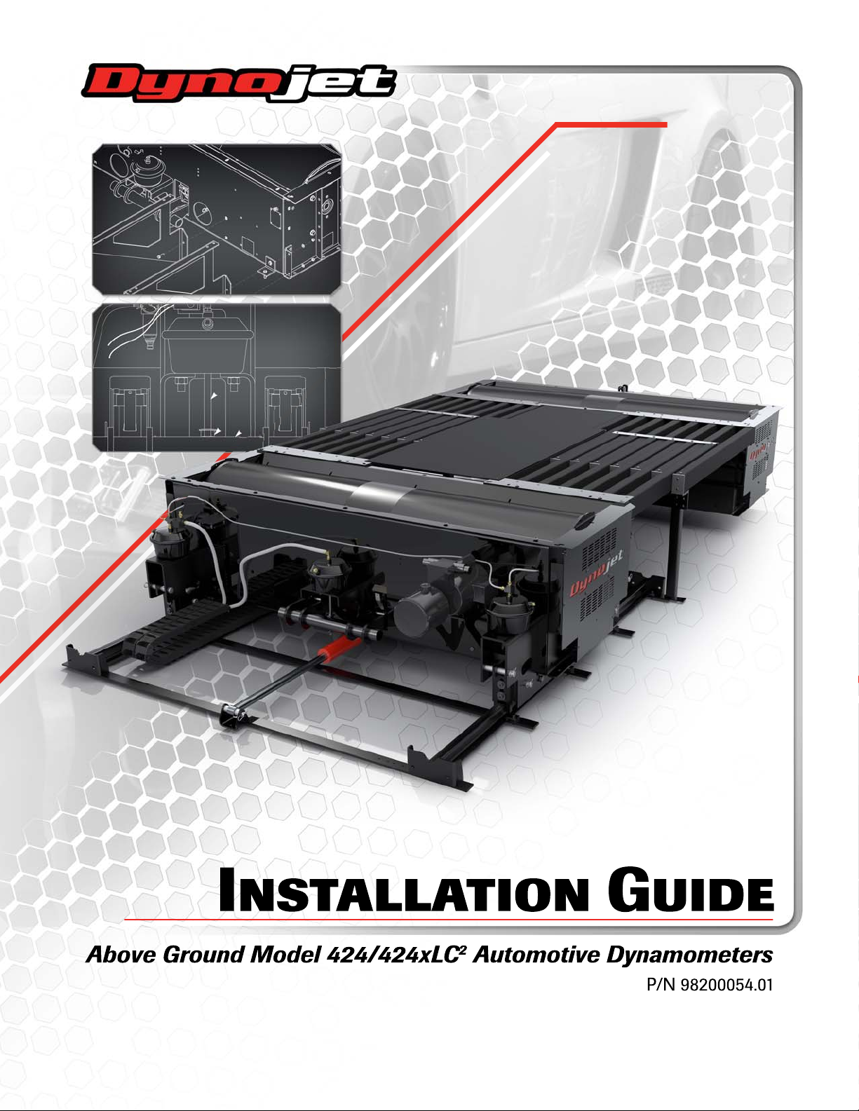
CHASSIS SPECIFICATIONS
of frame 218.44 cm (86.00 in.)
of frame with eddy current brake 321.23 cm (126.47 in.)
to top of frame 58.42 cm (23.00 in.)
to top of frame with feet/track
assembly
of frame 73.66 cm (29.00 in.)
including cradle assembly 130.18 cm (51.25 in.)
including air brake 93.83 cm (36.94 in.)
both frames, deck, bridge—full in 397.00 cm (156.30 in.)
both frames, deck, bridge—full in
with extension kit
both frames, deck, bridge—full out 487.68 cm (192.00 in.)
both frames, deck, bridge—full out
with extension kit
Length 208.92 cm (82.25 in.)
Width 218.44 cm (86.00 in.)
stationary crated dyno 2,114 kg (4,660 lb.)
4WD crated dyno 2,495 kg (5,500 lb.)
diameter 60.96 cm (24.00 in.)
width 205.74 cm (81.00 in.)
72.07 cm (28.375 in.)
422.40 cm (166.30 in.)
513.08 cm (202.00 in.)
Page 15
SPECIFICATIONS AND OPERATING REQUIREMENTS
Dynamometer Specifications and Requirements
A598D
93.83 cm
(36.94 in.)
frame and
air brake
115.49 cm (45.47 in.)
frame, air brake, and
interface kit
321.23 cm (126.47 in.)
frame and brake
65.58 cm (25.82 in.)
brake only
80.01 cm (31.50 in.)
brake to floor
106.93 cm (42.10 in.)
brake
218.44 cm (86.00 in.)
73.66 cm (29.00 in.)
72.02 cm (28.375 in.)
frame to floor
58.42 cm (23.00 in.)
frame only
Figure 1-1: Model 424 Stationary Dyno Dimensions
Version 1 Above Ground Model 424x/424xLC2 Automotive Dynamometer Installation Guide
1-5
Page 16
CHAPTER 1
Dynamometer Specifications and Requirements
Above Ground Model 424x/424xLC2 Automotive Dynamometer Installation Guide
1-6
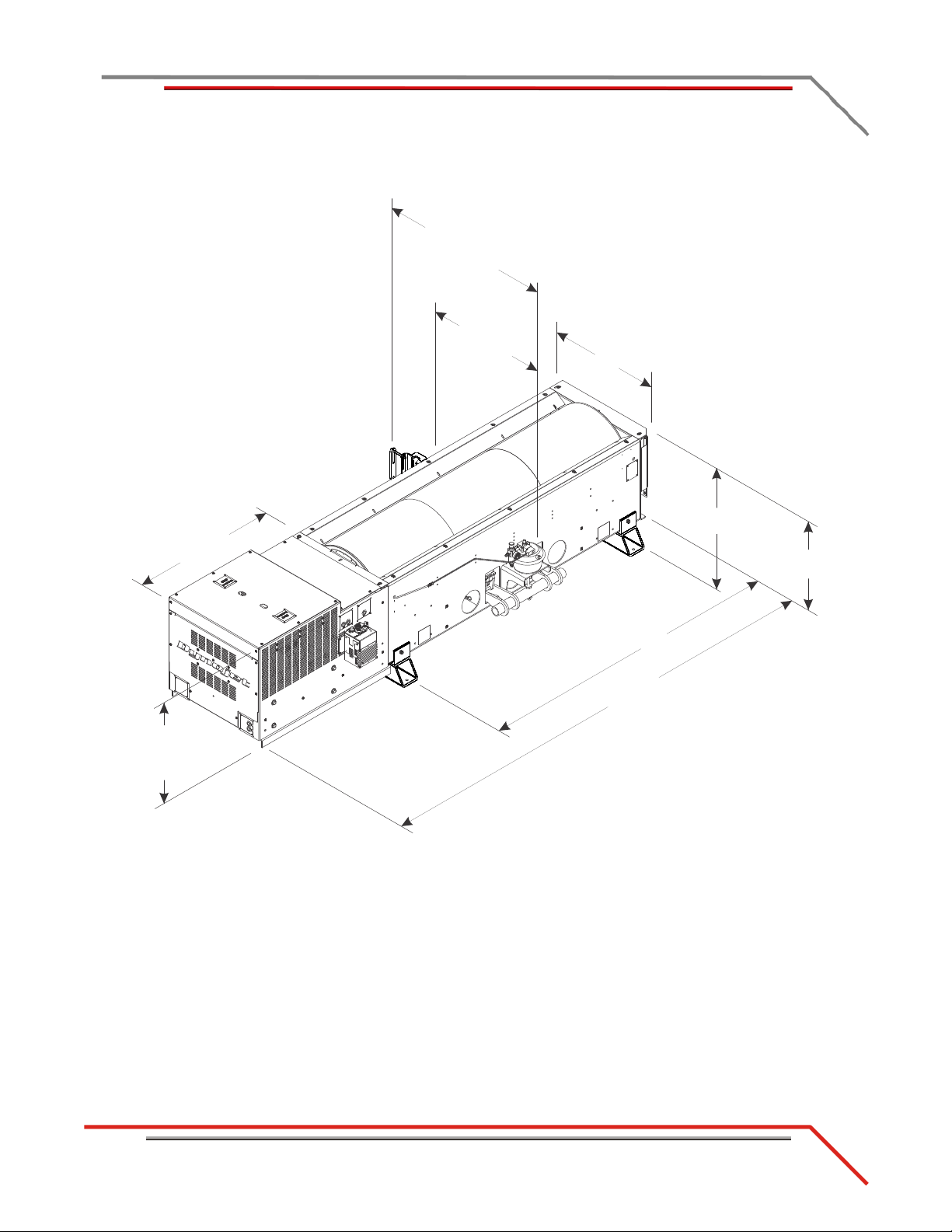
A599D
218.44 cm (86.00 in.)
frame only
321.23 cm (126.47 in.)
frame and brake
218.44 cm (86.00 in.)
track
224.15 cm (88.25 in.)
track
65.58 cm (25.82 in.)
brake only
80.01 cm (31.50 in.)
brake to floor
73.66 cm
(29.00 in.)
frame
130.18 cm (51.25 in.)
frame and cradle assembly
193.45 cm (76.16 in.)
frame, cradle assembly,
and deck
228.60 cm (90.00 in.)
deck
Figure 1-2: Model 424 4WD Dyno with Track Assembly Dimensions
Page 17
SPECIFICATIONS AND OPERATING REQUIREMENTS
Dynamometer Specifications and Requirements
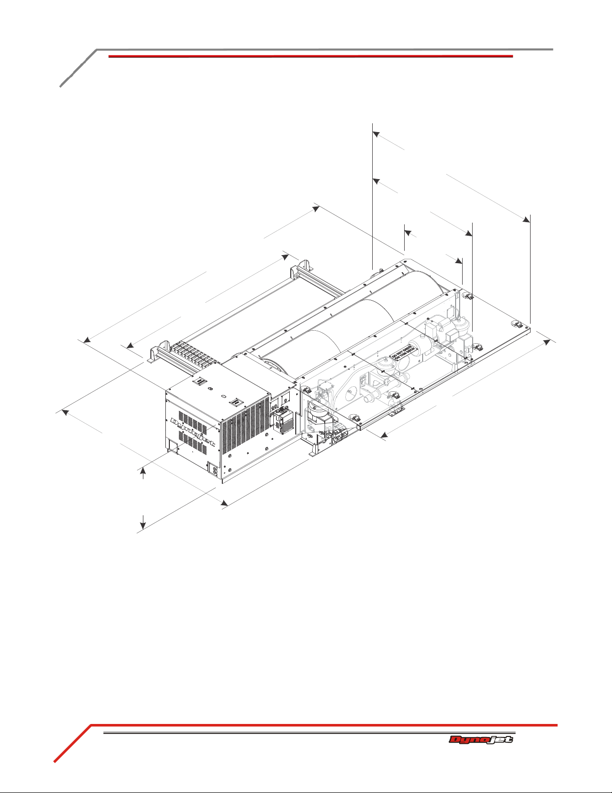
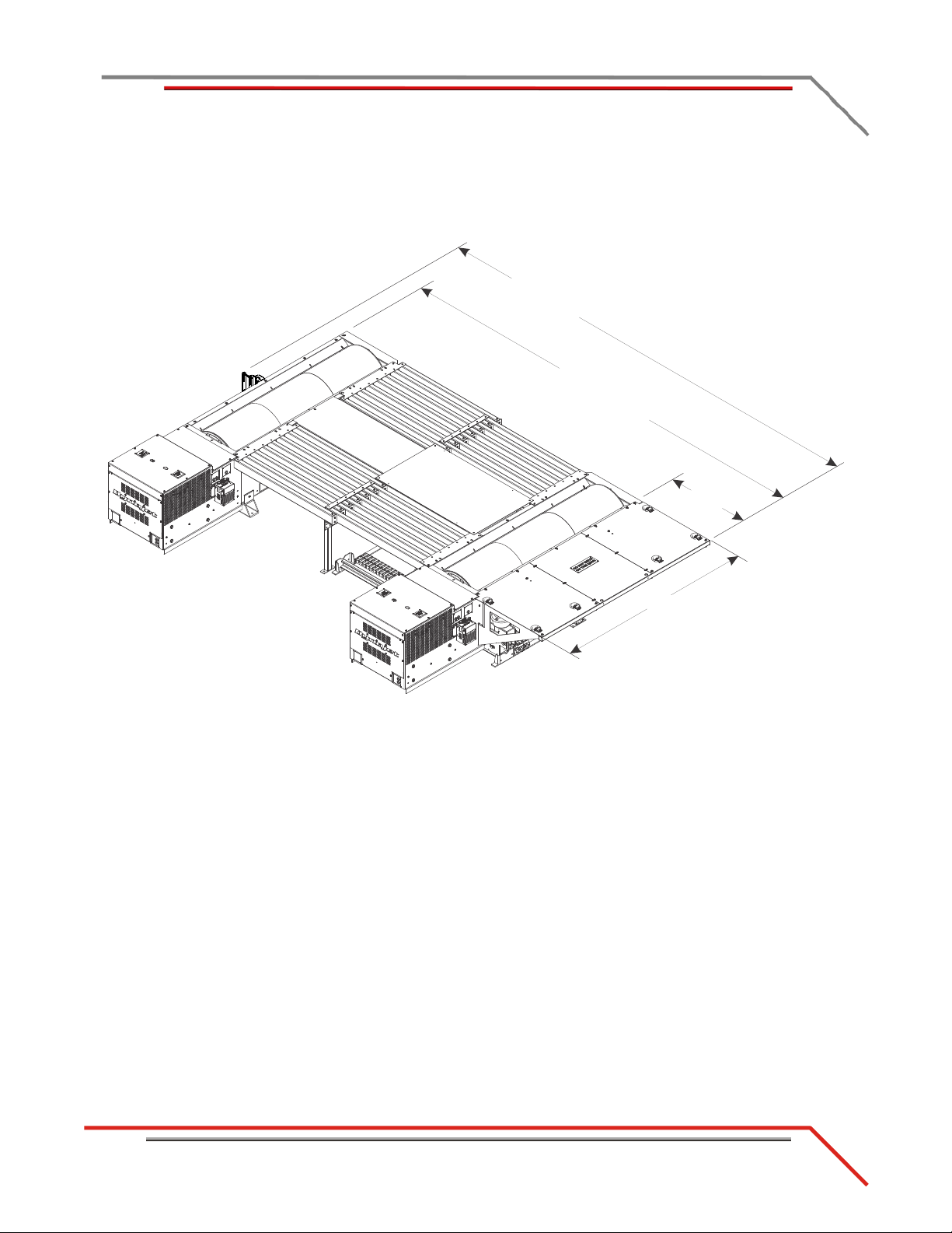
Figure 1-3: Model 424 4WD Dyno with Bridge and Deck Dimensions
A 600D
508.00 cm (200.00 in.)
deck full out to lift
416.56 cm (164.00 in.)
deck full in to lift
487.68 cm (192.00 in.)
frame and deck full out
397.00 cm (156.30 in.)
frame and deck full in
91.44 cm
(36.00 in.)
229.62 cm (90.40 in.)
deck
extension kit dimensions*
533.40 cm (210.00 in.)
deck full out to lift
441.96 cm (174.00 in.)
deck full in to lift
513.08 cm (202.00 in.)
frame and deck full out
422.40 cm (166.30 in.)
frame and deck full in
*requires extension parts,
inquire with Dynojet sales
Version 1 Above Ground Model 424x/424xLC2 Automotive Dynamometer Installation Guide
1-7
Page 18

CHAPTER 1
Dynamometer Specifications and Requirements
Above Ground Model 424x/424xLC2 Automotive Dynamometer Installation Guide
1-8
COMPRESSED AIR
The following requirements are needed for the air brake:
• Clean and dry air, between 100-140 psi
• shut off valve
• 1/4-inch NPT pipe thread connector (to attach air to the dyno), if air hose does not
have a 3/8-inch inside diameter
• have a 3/8-inch inside diameter
COMPUTER SPECIFICATIONS
You will need to provide a computer system to run the Power Core software.
description minimum specifications recommended specifications
Operating System Windows XP (service pack 3) or
higher
Processor Dual Core Processor, 2GHz or
faster
Memory 2GB System Ram 4GB System Ram or more
Hard Drive 100GB or larger
(54MB required for program)
Monitor/Graphics Card 1280x1024 (SXGA) resolution or
higher
Network Adapter 1 free 10/100 Mbps
RJ45 Ethernet Port
External Media CD Rom Drive CD Rom Drive
Printer Printer, if prints or needed Color printer, if prints are needed
Windows 7 or later
Intel Core i5 2.8GHz or faster
500GB or larger
(54 MB required for program)
1600x900 resolution or higher
1 free 100Mbps RJ45 or Wireless
DRILL AND DRILL BIT REQUIREMENTS
You will need to provide a drill and drill bit capabl e of dril ling holes in concrete. Refer
to Appendix A for more information on installing Red Head Anchors.
• drill bit size: 1/2-inch
• minimum hole depth: 1 5/8-inch (41.2 mm)
Page 19

SPECIFICATIONS AND OPERATING REQUIREMENTS
Dynamometer Specifications and Requirements
ELECTRICAL REQUIREMENTS
description specifications
Power Requirements: 4WD electronics 100-240 VAC, 50/60 Hz
Power Requirements: dyno electronics 100-240 VAC, 50/60 Hz
Power Requirements: hydraulic motor 110 VAC, 60 Hz, 20A/240 VAC, 60 Hz, 10A
Power Requirements: computer Per computer manufacturer specifications
Power Requirements: optional eddy
current brake
The hydraulic pump/motor power source and eddy current braking power source
require user supplied grounded electrical outlets with over current and short circuit
protection. These must be accessible to the operator to be used as a disconnect.
240v 30amp single phase circuit for each eddy current
brake
Refer to Appendix B for more information.
ENVIRONMENTAL REQUIREMENTS
description specifications
Temperature
operating min./max 10°C/50°C (50°F/122°F)
storage min./max 0°C/70°C (32°F/158°F)
Humidity 0 to 95% non condensing
Version 1 Above Ground Model 424x/424xLC2 Automotive Dynamometer Installation Guide
1-9
Page 20

CHAPTER 1
Dynamometer Specifications and Requirements
Above Ground Model 424x/424xLC2 Automotive Dynamometer Installation Guide
1-10
FIRE SUPPRESSION
Always have adequate fire suppression or fire extinguishers in your dyno room.
FORKLIFT REQUIREMENTS
You will need to provide equipment capable of lifting 2,495 kg (5,500 lb.) to lift the
crated dyno and to lift the dy no off the c r ate and into position in your dyno room. You
will also need a pair of straps capable of supporting the uncrated dyno. Dynojet
recommends using single loop style straps. Use an approved strap lifting attachment
for the forklift to prevent strap slippage. To use lift straps with bare forks is not OSHA
compliant.
HYDRAULIC MOTOR
You will need to provide up to five quarts of AW-68 hydraulic fluid for the hydraulic
motor.
PHONE AND INTERNET ACCESS
Dynojet recommends you have a phone close to the dyno to call for assistance in an
emergency. You may also wish to contact Dynojet to troubleshoot your dyno.
Internet access on your computer is desirable for contacting Dynojet and downl oading
new information and updates.
TIE-DOWN STRAPS
Dynojet recommends using tie-down straps for securing the vehicle on the dyno. The
dyno comes with an automotive tie-down package.
Page 21
SPECIFICATIONS AND OPERATING REQUIREMENTS
Model 424 Stationary and 4WD Dynamometer
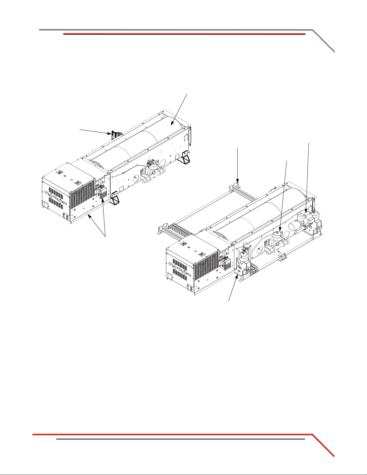
MODEL 424 STATIONARY AND 4WD DYNAMOMETER
A601D
Drum
precision balanced
and knurled
Air Brake
Track Assembly
Dyno Movement
Hydraulic Motor
Cradle Assembly
4WD Dyno
Stationary Dyno
Eddy Current Brake
with stiffener plate and
eddy current brake driver
Interface Guide
Figure 1-4: Model 424 Stationary and 4WD Dynamometer
Version 1 Above Ground Model 424x/424xLC2 Automotive Dynamometer Installation Guide
1-11
Page 22
CHAPTER 1
Model 424 4WD Dynamometer With Bridge and Deck
Above Ground Model 424x/424xLC2 Automotive Dynamometer Installation Guide
1-12
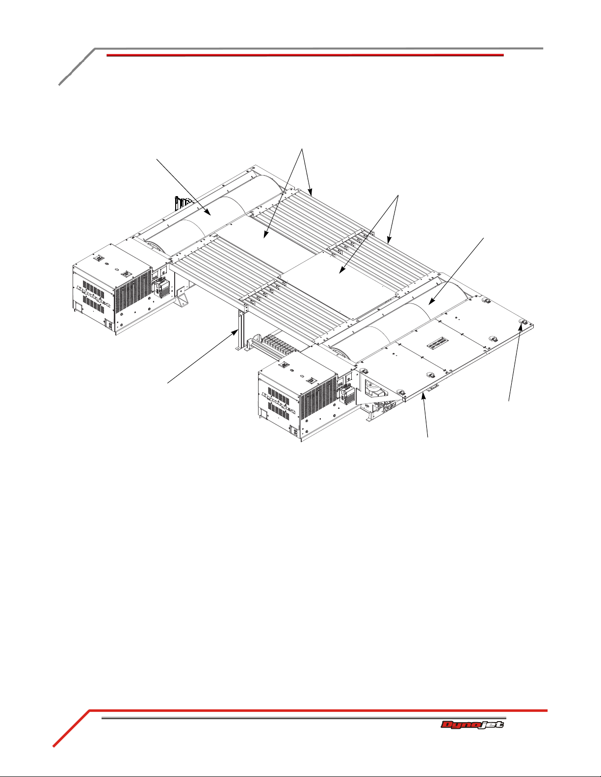
MODEL 424 4WD DYNAMOMETER WITH BRIDGE AND DECK
A602D
Deck
Stationary Dyno Bridge
and Center Cover
4WD Dyno
Stationary Dyno
4WD Dyno Bridge
and Center Cover
Tie-Down
Runner Support
Pillar
Figure 1-5: Model 424 4WD Dynamometer with Bridge and Deck
Page 23
SPECIFICATIONS AND OPERATING REQUIREMENTS
DynoWare RT Electronics
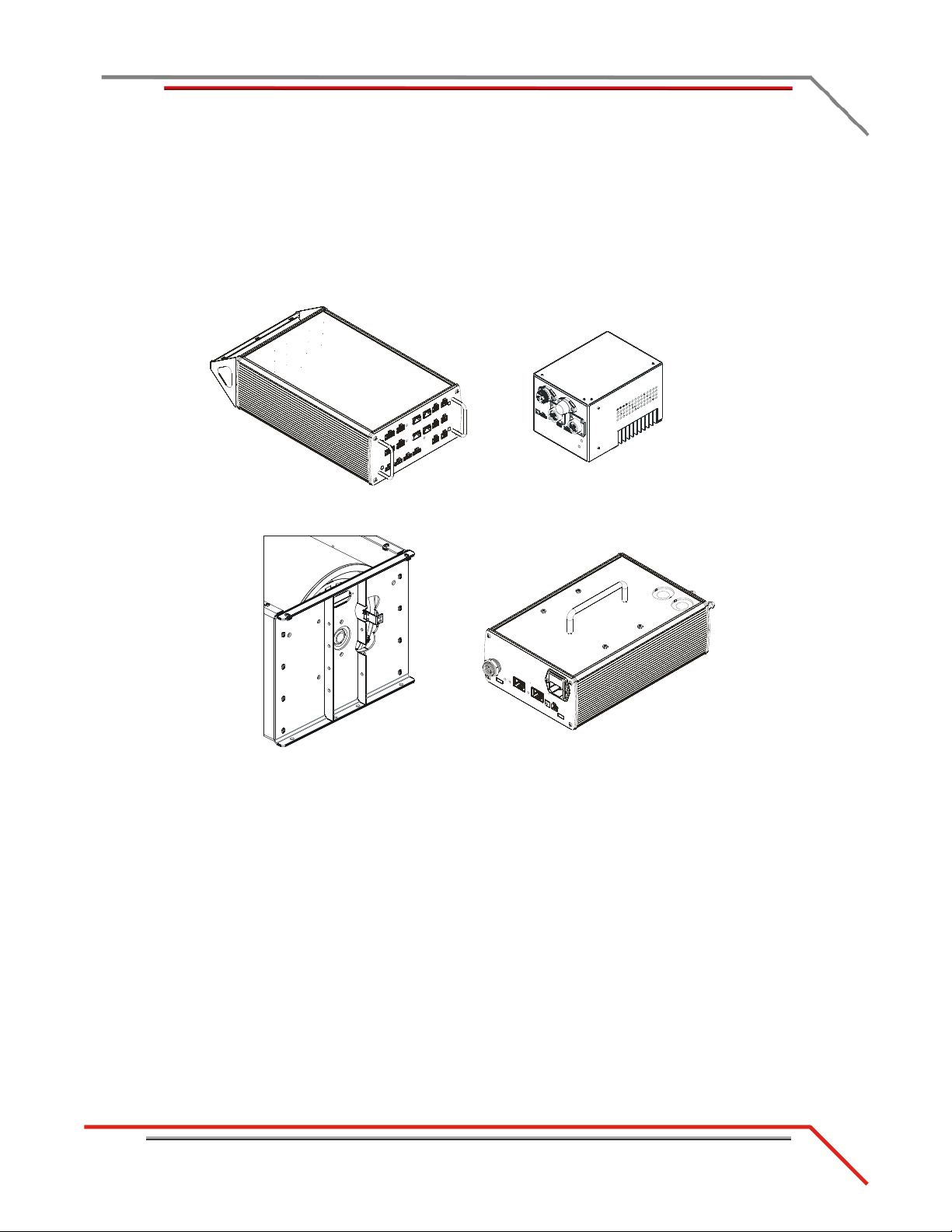
DYNOWARE RT ELECTRONICS
AD510
air fuel ratio
module
eddy current
brake driver
main module
speed pickup
The DynoWare RT electronics consists of a main module and a speed pickup. Optional
modules include the Air Fuel Ratio (AFR) module and the Eddy Current Brake (ECB)
driver. Use this section to identify the modules and connections. More detailed
information for configuring the DynoWare RT electronics can be found in the Power
Core Help.
Figure 1-6: DynoWare RT Electronics
Version 1 Above Ground Model 424x/424xLC2 Automotive Dynamometer Installation Guide
1-13
Page 24
CHAPTER 1
DynoWare RT Electronics
Above Ground Model 424x/424xLC2 Automotive Dynamometer Installation Guide
1-14
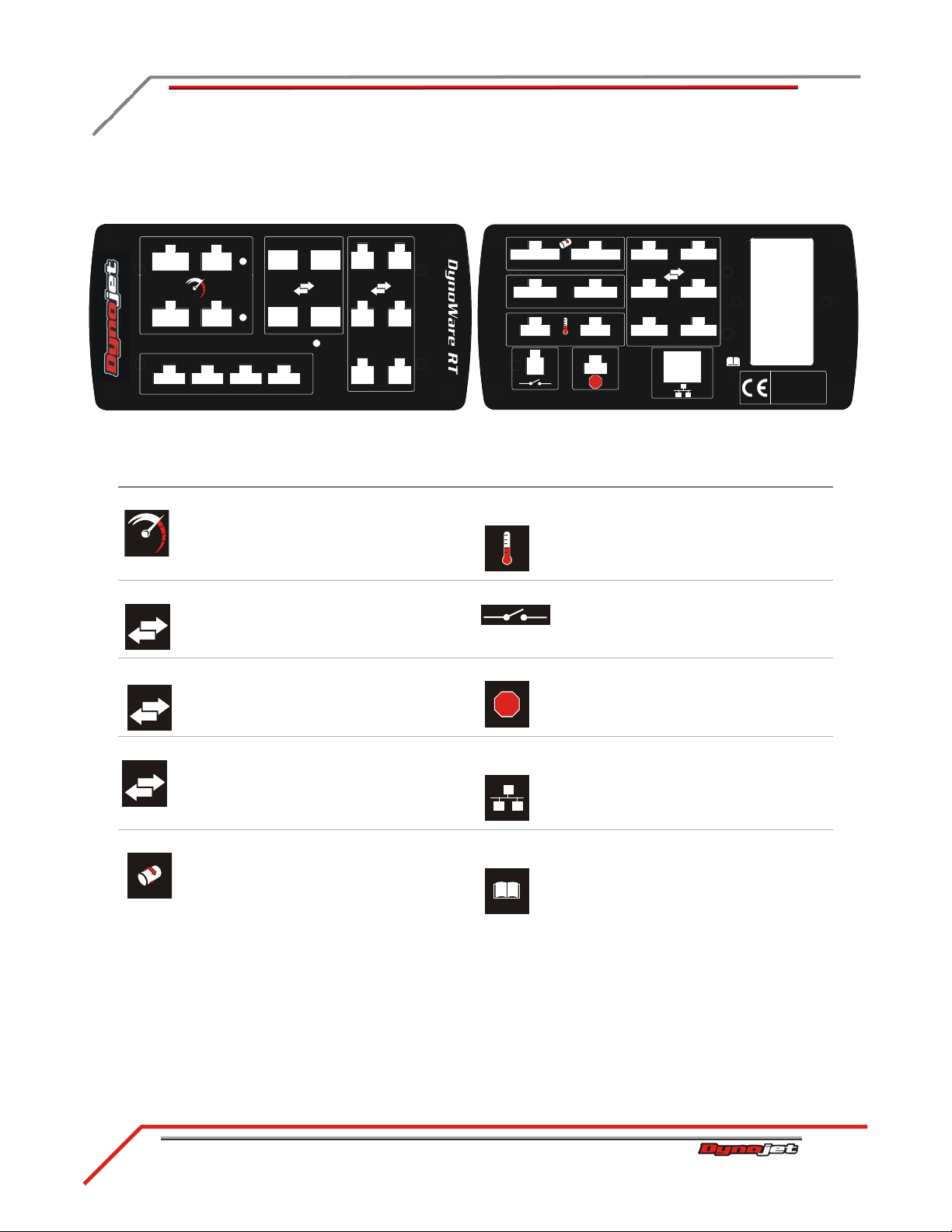
MAIN MODULE CONNECTIONS
1
2
1
2
12
Linx
!
C
Dynojet Research, Inc.
2191 Mendenhall Drive
N. Las Vegas, NV 89081
100-240 VAC
50-60 Hz
1.0 A
1
2
1234
Analog
Status
B
A
A
B
!
C
A description of the main module symbols and connections follows.
use this port to use this port to
RPM Inputs Connect inductive and optical
RPM inputs.
Auxiliary
Temperature
Connect to an auxiliary input
for an infrared temperature
sensor.
Communication I/O Connect to auxiliary Dynojet
Communication I/O Connect to auxiliary dyno
Communication I/O Connect to internal dyno
Drum Connect to the drum 1 and
products such as the Power
Commander, Wideband 2,
Power Vision, etc.
electronics such as the
pendant, atmospheric module,
AFR module, etc.
electronics and controllers
such as the ECB controller.
drum 2 speed inputs and
digital brake outputs.
Auxiliary Switch Connect to the brake air
pressure switch on 248 and
older 224 dynos.
Emergency Stop Connects the dyno electronics
to the emergency stop input on
the 200i/250i dynos.
Network
Connection
Connects the dyno electronics
to your computer or computer
network.
Refer to
Instructions
Do not press this button unless
instructed to do so by a Dynojet
Technician. This button may
need to be pressed to update
the device.
Page 25
SPECIFICATIONS AND OPERATING REQUIREMENTS
DynoWare RT Electronics
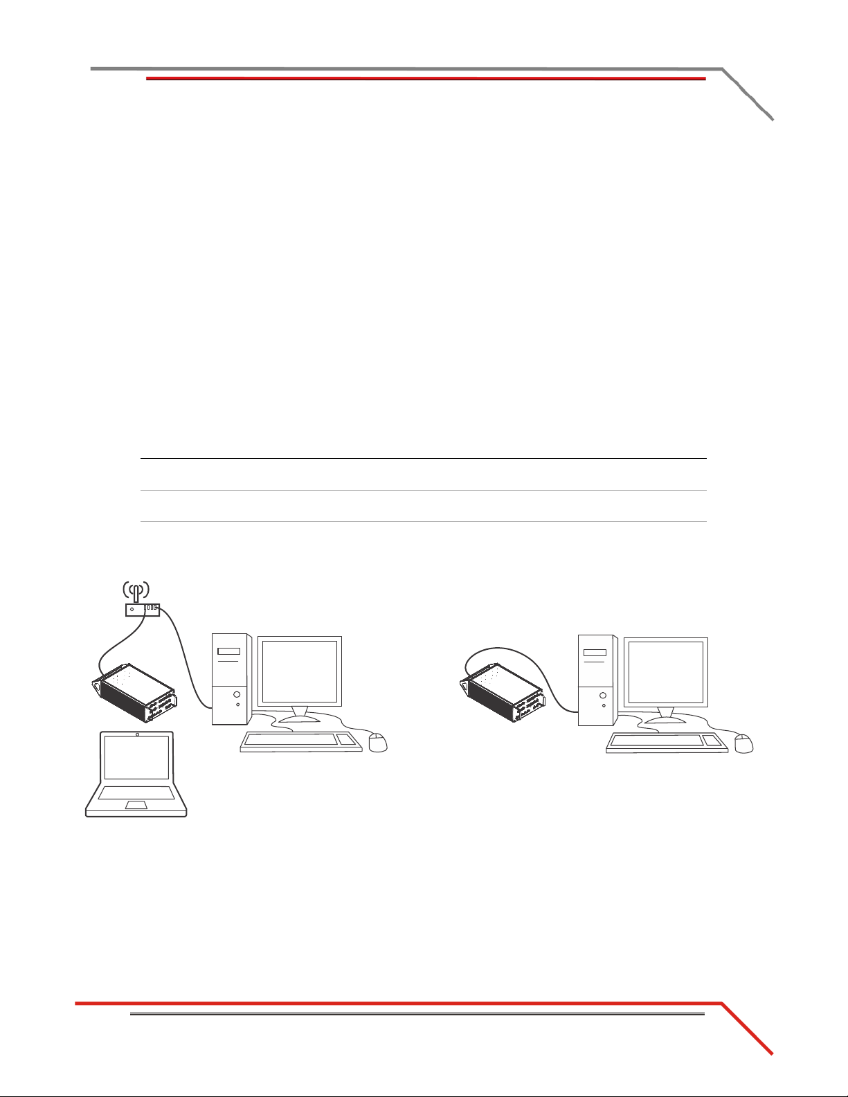
NETWORK CONNECTIONS
wireless network
internet and router
direct connection
point to point
The Dynojet DynoWare RT dyno electronics connects to your computer directly or
over a Local Area Network. If you have an existing network, connect t he DynoWare RT
main module to a router or a network switch on your network. If you don't have an
existing network, you can create a network for the DynoWare RT by connecting the
main module to a router.
There are some advantages to connecting the DynoWare RT to a network, particularly
a wireless network. With DynoWare RT on a network, you don't have to have one
dedicated computer for the dyno. Any computer on the network can connect and
operate the dyno. A wireless connection allows you to control the dyno from inside the
vehicle without a cable running to the DynoWare RT main module.
Note: Only one computer at a time can connect.
When the DynoWare RT main module is on a network connected to the internet,
automatic updates for both the box and software are possible.
connection method auto updates
Wireless Network
Internet
Wireless Network
Router
Direct Connection
Point to Point
Yes Yes Yes
multi-computer
connection wireless connection
Yes Yes
Figure 1-7: DynoWare RT Network Connections
Version 1 Above Ground Model 424x/424xLC2 Automotive Dynamometer Installation Guide
1-15
Page 26

CHAPTER 1
Lift Specifications and Requirements
Above Ground Model 424x/424xLC2 Automotive Dynamometer Installation Guide
1-16
LIFT SPECIFICATIONS AND REQUIREMENTS
Dynojet recommends installing the four-post lift before installing your dynamometer.
However, if space constraints make it difficult to install the lift first, the dynamometer
can be installed before the lift.
Dynojet acts as a liaison for Rotary Lifts, to ensure that you receive the proper
four-post lift. Dynojet recommends purchasing Rotary Lift’s SM14L four-post lift. The
information given and the images shown in this manual is currently based on Rotary
Lift’s SM14L four-post lift. This information is subject to change, contact Rotary Lift
for technical assistance and installation instructions, 1-800-532-6973.
description specifications
voltage single phase 208V-230V
Page 27

CHAPTER 2
This chapter will walk you through unpacking and installing the stationary dyno. To
ensure safety and accuracy in the procedures, perform the procedures as they are
described.
This chapter is divided into the following categories:
• Unpacking and Inspecting the Dyno, page 2-2
• Dyno Installation, page 2-7
• Eddy Current Brake Installation, page 2-15
S
TATIONARY
D
YNO INSTALLATION
Above Ground Model 424x/424xLC
2
Automotive Dynamometer Installation Guide
2-1
Page 28

CHAPTER 2
Unpacking and Inspecting the Dyno
Above Ground Model 424x/424xLC2 Automotive Dynamometer Installation Guide
2-2
UNPACKING AND INSPECTING THE DYNO
When you receive your dyno, examine the exterior of the shipping container for any
visible damage. If damage is detected at this stage, contact the shipper or Dynojet
before proceeding with unpacking.
Use the following steps to unload your dyno. You will need to provide equipment
capable of lifting a minimum of 2,114 kg (4,660 lb.) to move the crated dyno into
position in your dyno room. Refer to “Dynamometer Specifications and
Requirements” on page 1-4 for more information.
1 Move the crated dyno to a clear area near your dyno room.
2 Using a pry bar, or a large flat screwdriver, and a hammer, remove the top and
sides of the crate.
3 Inspect the exterior of the dyno for any indications of damage. Report any damage
immediately.
4 Remove the boxes and loose parts from the crate, verify their condition and
contents and set them aside.
Note: Some of these parts may have been shipped in the 4WD dyno crate
(crate 2).
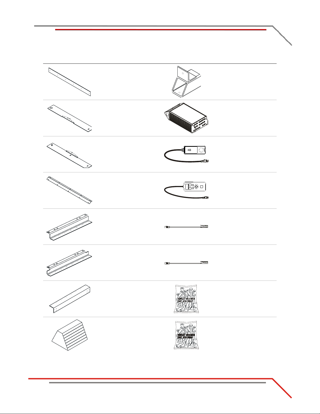
part description part description
runner tie strap (2)
P/N 21214701
network cable
P/N 42900000
runner clamp, short (2)
P/N 21214702
runner clamp plate (2)
P/N 21214703
runner slide (2)
P/N 21214704
car tie-down, 2" x 10' (4)
P/N 500-C10
car tie-down, hi-perf,
2" x 10' (2)
P/N 500-C10W/S
runner support pillar
assembly (4)
P/N 61314500
Page 29
STATIONARY DYNO INSTALLATION
Unpacking and Inspecting the Dyno
part description part description
runner tie slide (2)
P/N 21214705
riser foot assembly (4)
P/N 61319600
side deck
P/N 21216101
side deck, left
P/N 21216102
side deck, center
P/N 21216103
runner mount, short (2)
P/N 21514801
runner mount (2)
P/N 21514802
DynoWare RT main module
P/N 66100016
remote atmos assembly
P/N 66400011
pendant assembly
P/N 76100007
primary inductive
pickup (2)
P/N 76950201
secondary inductive
pickup (2)
P/N 76950203
runner support (2)
P/N 21514803
chock (4)
P/N 2A092
Version 1 Above Ground Model 424x/424xLC2 Automotive Dynamometer Installation Guide
bolt kit, 424 bridge
P/N 79110002
bolt kit, 4WD above ground
P/N 79110004
2-3
Page 30
CHAPTER 2
Unpacking and Inspecting the Dyno
Above Ground Model 424x/424xLC2 Automotive Dynamometer Installation Guide
2-4
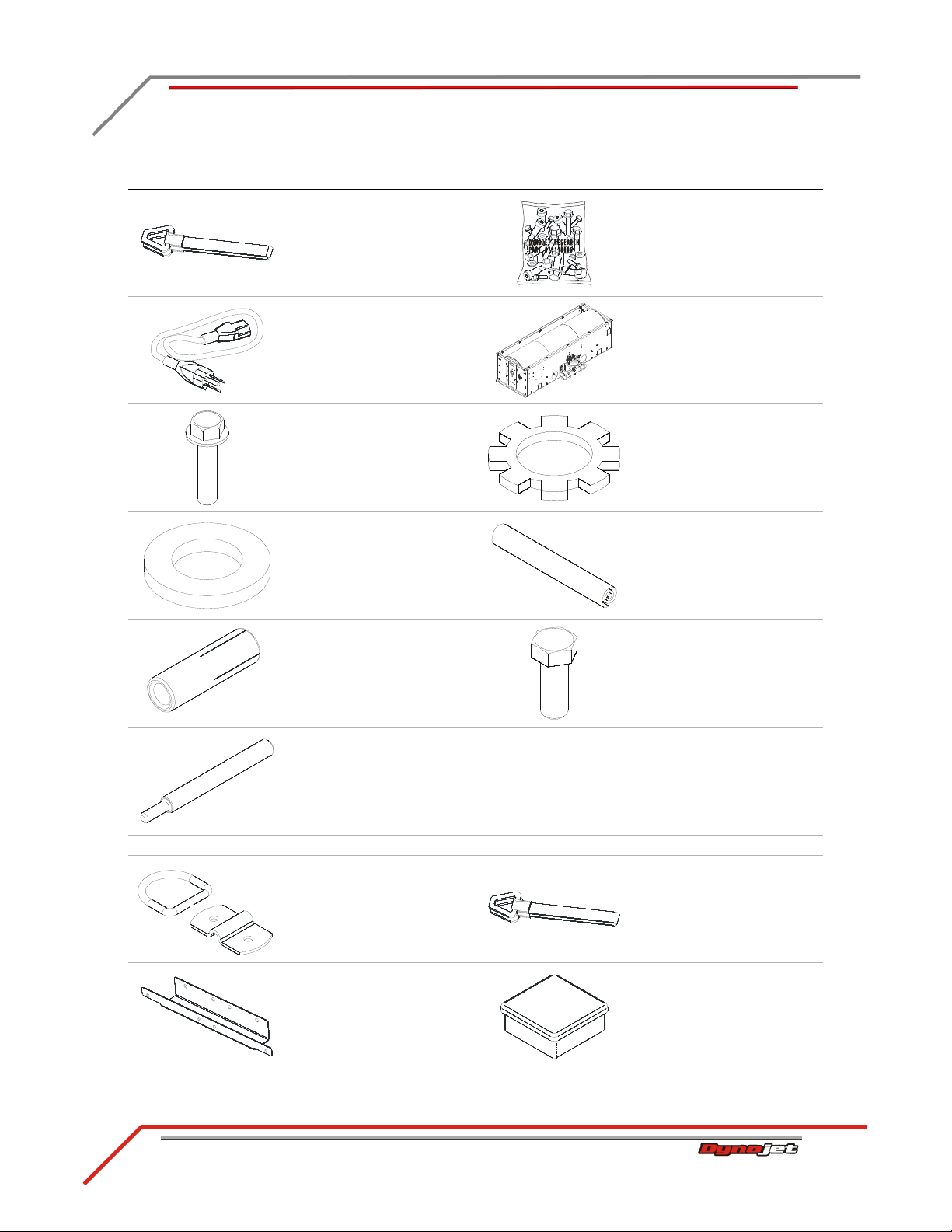
part description part description
axle strap, 21" (4)
P/N 30AS21
bolt kit, 3/8-16 x 5", Black
oxide
P/N 79110006
power cord, 125V, 10A
P/N 318110301
bolt, 3/8-16 x 1.5", flange,
hex (4)
P/N 36582471
washer, 3/8", flat (4)
P/N 36923100
anchor, redhead, 3/8" (4)
P/N 37513200
installation tool, redhead
anchor
P/N 37518200
model 224-2 dyno
P/N 81200000
washer, #8 ext star (4)
P/N 91114A009
banner, dynojet (2)
P/N D706
bolt, 3/8-16 x 1", hex (4)
P/N DM150-019-012
The following parts are included in the Above Ground Kit P/N 78112001:
ground hook/D-ring (6)
P/N 10111
mounting bracket, logo
panel (4)
P/N 21200004
axle strap, (2)
P/N 30AS72
cap plug, 1.75" x 1/2",
black (2)
P/N 35521420
Page 31

STATIONARY DYNO INSTALLATION
Unpacking and Inspecting the Dyno
part description part description
lower mounting bracket,
logo panel (2)
P/N 21200009
nut, 7/16-14, hex,
grade-5 (4)
P/N 36491100
center panel, deck
P/N 21214300
outer panel, deck (2) P/N
21214301
right drum guard
P/N 21216101
left drum guard
P/N 21216102
lateral drum guard (2)
P/N 21216103
screw, 1/4-20 x 5/8", panhead, torx (36)
P/N 36561045
bolt, 3/8-16 x 1.25", button
head flange allen, (12)
P/N 36582034
bolt, 7/16-14 x 1", hex (4)
P/N 36591670
washer, 7/16", flat (4)
P/N 36933100
logo panel assembly (2)
P/N 61100001
support angel, deck (2)
P/N 21610807
brace mount, deck (2) P/N
21614102
Version 1 Above Ground Model 424x/424xLC2 Automotive Dynamometer Installation Guide
interface guide assembly
P/N 71300000
bolt kit, 224-2 above ground
P/N 79110003
2-5
Page 32

CHAPTER 2
Unpacking and Inspecting the Dyno
Above Ground Model 424x/424xLC2 Automotive Dynamometer Installation Guide
2-6
part description part description
deck tube
P/N 21619103
washer, 3/8", flat (8)
P/N DM150-011-002
brace, deck (4)
P/N 21714200
bolt, 3/8-16 x 3/4", hex (8)
P/N DM150-019-008
Page 33

STATIONARY DYNO INSTALLATION
Dyno Installation
DYNO INSTALLATION
#
RECORD
A539D
place strap through
opening in dyno frame
dyno number
remove feet
set aside bolts
This section will walk you through removing the dyno from the crate and installing the
dyno in front of your lift. Refer to Appendix C for instructions on upgrading an
existing dyno.
REMOVING THE DYNO FROM THE CRATE
You will need to provide equipment capable of lifting a minimum of 2,114 kg
(4,660 lb.) to lift the dyno off the crate and into position in your dyno room. You will
also need a pair of straps capable of supporting the same weight. Dynojet recommends
using two 2-inch x 6-foot single loop style straps. Refer to “Forklift Requirements” on
page 1-7.
Be sure you record the dynamometer number on the inside cover of this
manual.
1 Remove the crate braces that support the top portion of the crate.
2 Remove the four lag bolts and washers securing the dyno to the crate base using a
9/16-inch socket, open or box end wrench.
3 Remove and set aside the four flange bolts securing the crate feet to the dyno.
4 Route the loop strap through the opening in the dyno frame and through itself.
Pull the strap tight. Do this on each side of the dyno frame.
5 Push the forklift forks together.
6 Place each loop strap over both forks.
Note: The straps must be the same length and meet in the middle. Verify each
loop strap is over both forks to prevent the forks from being pulled apart.
7 Using the forklift, carefully lift the dyno off the crate and move it into position in
your dyno room.
Figure 2-1: Loop Strap Placement
Version 1 Above Ground Model 424x/424xLC2 Automotive Dynamometer Installation Guide
2-7
Page 34

CHAPTER 2
Dyno Installation
Above Ground Model 424x/424xLC2 Automotive Dynamometer Installation Guide
2-8
8 With the dyno on the forklift, secure the four feet to the bottom of the dyno using
AD540
feet
the four 3/8 x 1.5-inch flange bolts removed earlier.
Note: If the feet are already installed, skip this step.
Figure 2-2: Install the Feet
Page 35

STATIONARY DYNO INSTALLATION
Dyno Installation
PLACING THE DYNO IN FRONT OF THE LIFT
lift runway
lift runway
cross member
interface bracket
10.16 cm
(4.00 in.)
1 Verify the interface bracket faces the lift as shown in Figure 2-3.
2 Verify the lift is in the down position.
3 Using the forklift, bring the dyno in front of the lift. The dyno should be about
10.16 cm (4.00 in.) from the lift cross member.
4 Center the dyno drum with the lift runways.
5 Gently lower the dyno into position.
Version 1 Above Ground Model 424x/424xLC2 Automotive Dynamometer Installation Guide
Figure 2-3: Dyno with Lift
2-9
Page 36

CHAPTER 2
Dyno Installation
Above Ground Model 424x/424xLC2 Automotive Dynamometer Installation Guide
2-10
INSTALLING THE INTERFACE GUIDE
A512D
lift cross
member
interface guide
interface guide with the pin facing
the dyno and near the bottom of
the lift cross member
The interface guide secures the dyno to the four-post lift. It is a good idea to install
your interface guide before anchoring your dyno to the ground. If you have the
interface roller assembly, refer to Appendix E.
You will need the following parts:
• 21600000 Interface Bar
• 21600001 Interface Bracket
secured to the dyno using P/N 36582471 Bolt, 3/8-16 x 1.5",
Flange-Hex (2)
• 36488100 Nut, 3/8-16, Nylock (2)
• 36500000 Bolt, 3/8-16 x 4.5", Hex, Full Thread (2)
• 36923100 Washer, 3/8", Hardened, Flat, Steel (4)
• 61100000 Interface Guide
1 Raise the lift until the bottom of the lift is approximately 86.36 cm (34.00 in.)
above the floor.
2 Loosely attach the interface guide to the lift cross member using two
3/8-16 x 4.5-inch bolts, four 3/8-inch flat washers, and two 3/8-inch nylock nuts.
Note: Verify the interface guide with the pin is facing the dyno and is near the
bottom of the lift cross member.
Figure 2-4: Interface Guide and Lift Cross Member
Page 37

STATIONARY DYNO INSTALLATION
Dyno Installation
3 Align the interface guide pin on the lift cross member with the interface bracket on
A 513D
interface bracket
on dyno
(dyno not shown
for clarity)
pin
mounting bolt
lift cross member
the dyno. The interface bracket is already installed on the dyno.
Note: The distance between the dyno and the lift may need to be adjusted.
4 Lower the lift until the interface guide pin just starts to enter the interface bracket
on the dyno.
Figure 2-5: Align the Interface Bracket and the Interface Guide
Version 1 Above Ground Model 424x/424xLC2 Automotive Dynamometer Installation Guide
2-11
Page 38

CHAPTER 2
Dyno Installation
Above Ground Model 424x/424xLC2 Automotive Dynamometer Installation Guide
2-12
5 Verify the interface guide clears the interface bracket by 1/8-inch to 1/4-inch as
interface guide on
cross member
interface bracket
on dyno
0.125" to .250"
shown in Figure 2-6.
6 Slide the interface guide up until the bottom bolt touches the cross member.
Lower the top bolt down in the slots until it touches the cross member.
7 Tighten the hardware securing the interface guide to the lift cross member.
Note: The lower and upper interface guide mounting bolts should touch the lift
cross member.
8 Raise and lower the lift several times to make sure that the interface guide is
working smoothly. Adjust the interface guide if needed.
9Verify the lift can be lowered down to floor level.
Figure 2-6: Verify Distance Between Interface Guide and Interface Bracket
Page 39

STATIONARY DYNO INSTALLATION
Dyno Installation
ANCHORING THE DYNO
A514D
secure dyno
to floor
secure dyno to
floor
lift
Dynojet recommends you secure your dyno to the floor in your dyno room using
concrete anchors. Use the following instructions to secure the dyno to the floor.
You will need the following parts:
• 36923100 Washer, 3/8", Hardened, Flat, Steel (4)
• 37513200 Anchor, Redhead, 3/8" (4)
• 37518200 Redhead Anchor Installation Tool
• DM150-019-012 Bolt, 3/8-16 x 1", Hex (4)
1 Using the mounting feet as a template, mark and drill each hole needed to secure
the four dyno feet to the floor.
2 Install four Red Head anchors. Refer to Appendix A for installation instructions.
3 Secure each mounting foot to the floor using one 3/8-16 x 1-inch hex-head bolt
and one 3/8-inch flat washer.
Figure 2-7: Secure the Dyno to the Floor
Version 1 Above Ground Model 424x/424xLC2 Automotive Dynamometer Installation Guide
2-13
Page 40

CHAPTER 2
Dyno Installation
Above Ground Model 424x/424xLC2 Automotive Dynamometer Installation Guide
2-14
INSTALLING THE AIR FITTINGS
A560D
existing air inlet fitting
brake solenoid
assembly
street tee
barbed hose fitting
bushing and
elbow fitting
Before the stationary dyno can be used with the 4WD dyno, the existing air fittings on
the stationary dyno must be upgraded.
You will need the following parts:
• 3400X4 Fitting, Street Tee
• 141900001 Fitting, Barbed Hose
• 34122231 Bushing, 1/4"F x 3/8"M, Brass
• 34161320 Elbow-90, 3/8"H x 1/4"P
1 Remove the existing air inlet fitting from the brake solenoid assembly.
2 Install the street tee.
3 Replace the air inlet fitting removed earlier.
4 Install a barbed hose fitting into the street tee.
5 Remove the existing plug from the air can.
6Install one 3/8-1/4-inch bushing and elbow fitting.
Figure 2-8: Upgrade the Air Fittings
Page 41

STATIONARY DYNO INSTALLATION
Eddy Current Brake Installation
EDDY CURRENT BRAKE INSTALLATION
AD603
Refer to Chapter 4 for eddy current brake installation instructions and install your
eddy current brake at this time.
Figure 2-9: Eddy Current Brake
Version 1 Above Ground Model 424x/424xLC2 Automotive Dynamometer Installation Guide
2-15
Page 42

Page 43

CHAPTER 3
4WD D
This chapter will walk you through unpacking and installing the 4WD dyno . To ensure
safety and accuracy in the procedures, perform the procedures as they are described.
This chapter is divided into the following categories:
• Unpacking and Inspecting the Dyno, page 3-2
• Track Assembly, page 3-5
• Dyno Installation, page 3-9
• Eddy Current Brake Installation, page 3-12
• Cable Routing, page 3-13
•Hydraulic Movement Installation, page 3-23
• Air Can Sleeve, page 3-32
• 4WD Movement Test, page 3-33
• Bridge Installation—Stationary Dyno, page 3-34
• Bridge Installation—4WD Dyno, page 3-40
• Deck Installation, page 3-45
YNO INSTALLATION
• Logo Panel Installation, page 3-51
Above Ground Model 424x/424xLC
2
Automotive Dynamometer Installation Guide
3-1
Page 44

CHAPTER 3
Unpacking and Inspecting the Dyno
Above Ground Model 424x/424xLC2 Automotive Dynamometer Installation Guide
3-2
UNPACKING AND INSPECTING THE DYNO
When you receive your dyno, examine the exterior of the shipping container for any
visible damage. If damage is detected at this stage, contact the shipper or Dynojet
before proceeding with unpacking.
Use the following steps to unload your dyno. You will need to provide equipment
capable of lifting a minimum of 2,495 kg (5,500 lb.) to move the crated dyno into
position in your dyno room. Refer to “Dynamometer Specifications and
Requirements” on page 1-4 for more information.
1 Move the crated dyno (crate 2) to a clear area near your dyno room.
2 Using a pry bar, or a large flat screwdriver, and a hammer, carefully remove the
top and sides of the crate.
Note: At this point, you will want to inspect the exterior of the dyno for any
indications of damage. Report any damage immediately.
3 Remove the following parts from the crate and set aside.
Note: Some of these parts may have been shipped in the stationary dyno crate
(crate 1).
4 Verify the contents of the hardware boxes and set aside.
Note: The hardware required for the 4WD dyno installation may be packed in the
stationary dyno crate (crate 1).
part description part description
bridge cover, stationary
dyno
P/N 21219511
anchor, redhead, 3/8" (12)
P/N 37513200
bridge cover, 4WD dyno
P/N 21219512
rail (2)
P/N 21514282
rail tie (3)
P/N 21716400
installation tool, redhead
anchor
P/N 37518200
cylinder mount, dyno
P/N 61300016
cylinder mount, floor
P/N 61300061
Page 45

4WD DYNO INSTALLATION
Unpacking and Inspecting the Dyno
part description part description
spacer, 424 hydraulic
movement (2)
P/N 26100000
rail tie assembly (2)
P/N 61314300
spacer, rail clamp (8)
P/N 26152020
rail clip (10)
P/N 31619500
clevis pin, 3/4 x 4.5" (2)
P/N 32900000
hairpin cotter,
7/16 x 3/4" (2)
P/N 32904080
weight (4)
P/N 35430899
rail clamp (4)
P/N 61314700
calibration arm assembly
P/N 61319001
runner assembly (30)
P/N 61319500
washer, 1/4", flat (4)
P/N DM150-009-003
washer, 3/8", flat (4)
P/N DM150-011-002
bolt, 3/8-16 x 1.5", flange,
hex (12)
P/N 36582471
bolt, shoulder, 3/8-16,
1/2"D x 1"L (8)
P/N 36800973
Version 1 Above Ground Model 424x/424xLC2 Automotive Dynamometer Installation Guide
bolt, 1/4 x 1/2", hex (4)
P/N DM150-011-005
bolt, 3/8-16 x 1", hex (6)
P/N DM150-019-012
3-3
Page 46

CHAPTER 3
Unpacking and Inspecting the Dyno
Above Ground Model 424x/424xLC2 Automotive Dynamometer Installation Guide
3-4
5 Remove the crate braces that support the top portion of the crate.
6 Remove the four lag bolts and washers securing the dyno to the crate base using a
9/16-inch socket, open or box end wrench.
7 Before removing the dyno from the crate, you will need to install the track
assembly in your dyno room. Refer to the instructions page 3-5 for more
information on installing the track assembly.
Page 47

4WD DYNO INSTALLATION
Track Assembly
TRACK ASSEMBLY
The stationary dyno must be installed before proceeding with the 4WD dyno
installation. Refer to chapter 2 for stationary dyno installation instructions.
Before installing the track assembly, layout the entire track assembly using the
following instructions and Figure 3-1 for position and alignment.
You will need the following parts:
• 37513200 Anchor, Redhead, 3/8" (10)
• 37518200 Redhead Anchor Installation Tool
1 Line up the center line of the track assembly with the center line of the stationary
dyno.
2 Measure the following distances and set the track assembly as listed below and
shown in Figure 3-1.
• The track assembly should be 128.27 cm (50.50 in.) from the stationary dyno
without the extension kit and 153.67 cm (60.50 in.) with the extension kit.
• The distance between the inside of the rails should be 184.15 cm
(72.50-inches +/- 0.06 in.).
• The distance from the first rail tie assembly to the first rail tie is 49.37 cm
(19.438 in.).
• The distance from the first rail tie assembly to the second rail tie is 103.82 cm
(40.875 in.).
• The distance from the first rail tie assembly to the third rail tie is 158.28 cm
(62.313 in.).
3 Verify the track assembly is square. Measure from corner to corner and verify
these measurements are equal.
4 Mark and drill all ten holes, five on each side of the track assembly.
5 Set the track assembly aside.
6 Install the ten Red Head anchors. Refer to Appendix A for installation
instructions.
Version 1 Above Ground Model 424x/424xLC2 Automotive Dynamometer Installation Guide
3-5
Page 48

CHAPTER 3
Track Assembly
Above Ground Model 424x/424xLC2 Automotive Dynamometer Installation Guide
3-6
A604
D
128.27 cm
(50.50 in.)
without extension
153.67 cm
(60.50 in.)
with extension
(requires extension
parts, inquire with
Dynojet sales)
49.37 cm
(19.438 in.)
103.82 cm
(40.875 in.)
158.28 cm
(62.313 in.)
184.15 cm
(72.5 in.)
center line for
stationary dyno and
track assembly
stationary dyno
track layout
mark and
drill holes
first rail tie assembly
first rail tie
second rail tie
third rail tie
last rail tie assembly
Figure 3-1: Mark and Drill Holes for the Track Assembly
Page 49

4WD DYNO INSTALLATION
Track Assembly
INSTALLING THE TRACK ASSEMBLY
AD045
rail clamps
rail
first rail tie
assembly
last rail tie
assembly
rail tie
holes for cable
track assembly
Once all the holes are marked and drilled, install the track assembly.
You will need the following parts:
• 21514282 Rail (2)
•21716400 Rail Tie (3)
• 31619500 Rail Clip (10)
•36582471 Bolt, 3/8-16 x 1.5", Flange-Hex (10)
• 61314300 Rail Tie Assembly (2)
• 61314700 Rail Clamp (4)
1 Layout the first and last rail tie assemblies and the rail ties. Use the holes you
marked and drilled for placement of the rail tie assemblies and rail ties.
Note: The first rail tie has four holes for securing the cable track assembly. Verify
this rail tie assembly is closest to the stationary dyno.
2 Place the rail clamps over the rails.
3 Place the rails into the rail tie assemblies.
Note: For clarity, the stationary dyno is not shown.
Figure 3-2: Install the Track Assembly
Version 1 Above Ground Model 424x/424xLC2 Automotive Dynamometer Installation Guide
3-7
Page 50

CHAPTER 3
Track Assembly
Above Ground Model 424x/424xLC2 Automotive Dynamometer Installation Guide
3-8
4 Loosely install the ten rail tie clips using one 3/8-16 x 1.5-inch flange-hex bolt per
AD103
bolt
rail tie clip
rail
anchor in floor
rail tie
clip. There are five rail tie clips on each side of the track assembly.
5 Verify the track assembly is square and make any necessary adjustments.
6Tighten all ten bolts.
Note: For clarity, the stationary dyno is not shown.
Figure 3-3: Install the Rail Tie Clips
Page 51

4WD DYNO INSTALLATION
Dyno Installation
DYNO INSTALLATION
#
RECORD
AD351
dyno number
place strap through
opening in dyno frame
hydraulic ram
With the track assembly installed and secured to the floor, you are ready to install the
4WD dyno. This section will walk you through removing the dyno from the crate and
securing the dyno to the track.
REMOVING THE DYNO FROM THE CRATE
You will need to provide equipment capable of lifting a minimum of 2,495 kg
(5,500 lb.) to lift the dyno off the crate and into position in your dyno room. You will
also need a pair of straps capable of supporting the same weight. Dynojet recommends
using two 2-inch x 6-foot single loop style straps.
Be sure you record the dynamometer number on the inside cover of this
manual
1 Route the loop strap through the opening in the dyno frame and through itself.
Pull the strap tight. Do this on each side of the dyno frame.
2 Push the forklift forks together.
3 Place each loop strap over both forks.
Note: The straps must be the same length and meet in the middle. Verify each
loop strap is over both forks to prevent the forks from being pulled apart.
4 Using the forklift, carefully lift the dyno off the crate and move it into position in
your dyno room.
Use caution when handling the hydraulic ram and the hoses connecting
the ram to the hydraulic motor.
Figure 3-4: Loop Strap Placement
Version 1 Above Ground Model 424x/424xLC2 Automotive Dynamometer Installation Guide
3-9
Page 52

CHAPTER 3
Dyno Installation
Above Ground Model 424x/424xLC2 Automotive Dynamometer Installation Guide
3-10
PLACING THE DYNO ON THE TRACK
A605D
rail clamp
hydraulic movement
motor facing away
from stationary dyno
cable track under dyno and
towards stationary dyno
rail clamp
cradle
assembly
pin and cotter pin
stationary dyno
You will need to keep the cable track routed underneath the dyno and towards the
stationary dyno.
You will need the following parts:
• 26152020 Spacer, Rail Clamp (8)
• 36800973 Bolt, Shoulder, 3/8-16, 1/2"D x 1"L (8)
1 Remove the cotter pin and pin from all four cradle assemblies as shown in
Figure 3-5.
2 Verify the rail clamps are positioned as shown in Figure 3-5.
3 Verify the hydraulic movement motor is facing away from the stationary dyno.
4 Using the forklift, gently lower the dyno onto the rails.
Figure 3-5: Lower the Dyno onto the Rails
Page 53

4WD DYNO INSTALLATION
Dyno Installation
5 Secure the rail clamps to the cradle assembly on the dyno using two 3/8-inch
AD353
spacer
bolt
shoulder bolts and two spacers each.
6 Replace the pins and cotter pins removed earlier from the four cradle assemblies
as shown in Figure 3-5.
7 Move the rail clamps up and down and verify they move freely.
8 Roll the dyno back and forth and verify the rail clamps are not binding and the
track assembly is square.
Note: For clarity, the stationary dyno is not shown.
Figure 3-6: Secure the Dyno to the Rail Clamps
Version 1 Above Ground Model 424x/424xLC2 Automotive Dynamometer Installation Guide
3-11
Page 54

CHAPTER 3
Eddy Current Brake Installation
Above Ground Model 424x/424xLC2 Automotive Dynamometer Installation Guide
3-12
EDDY CURRENT BRAKE INSTALLATION
AD606
Refer to Chapter 4 for eddy current brake installation instructions and install your
eddy current brake at this time.
Figure 3-7: Eddy Current Brake
Page 55

4WD DYNO INSTALLATION
Cable Routing
CABLE ROUTING
B
B
Use the following instructions to identify and route the cables for dynos with and
without eddy current brakes.
IDENTIFYING THE CABLES
cable brief routing description
A - 318110301 power cable connects the DynoWare RT to a power outlet
B - 318110301 power cable connects the 4WD board power supply with cable (N)
to a power outlet
C - 42900000 network cable connects the DynoWare RT to your local network
D - 66400011 remote atmos cable assembly connects to the DynoWare RT
E - 66952003 controller cable connects the eddy current brake to the eddy current
brake driver
F - 76100007 CAN pendant cable assembly connects to the DynoWare RT
G - 76950135 hydraulic pump power cable connects to a power outlet
H - 76950201 primary RPM pick up cable
- 76950203 secondary pick up cable
I - 76950311 power cable connects the eddy current brake driver to a power
J - 76950547 speed pick up/brake cable connects the brake solenoid and speed pick up to the
connects to the DynoWare RT
outlet
DynoWare RT
Version 1 Above Ground Model 424x/424xLC2 Automotive Dynamometer Installation Guide
3-13
Page 56

CHAPTER 3
Cable Routing
Above Ground Model 424x/424xLC2 Automotive Dynamometer Installation Guide
3-14
cable brief routing description
C
K - 76950568 CAN control cable connects the eddy current brake driver to the
DynoWare RT
L - 76950569 IR temp sensor cable connects the temp sensor to the eddy current brake
driver
M - 76950574 load cell cable connects the load cell to the eddy current brake
N - 76952008 4WD power supply with cable connects the 4WD board to the 4WD power cable (B)
O - 76953004 dyno movement pendant cable connects to the 4WD board
P - air hose connects the air can on the stationary dyno to your
Q - rail brake air hose connects the air can on the 4WD dyno to the T fitting
R - drum brake air hose connects the drum brake air can on the 4WD dyno to
driver
clean dry shop air (customer supplied)
on the stationary dyno air can
the drum brake air can on the stationary
Page 57

4WD DYNO INSTALLATION
Cable Routing
ROUTING THE CABLES—WITHOUT THE EDDY CURRENT BRAKES
Use the following instructions along with Figure 3-8 on page 3-16 for routing cables
without eddy current brakes.
You will need the following parts:
• DM150-009-003 Washer, 1/4", Flat (4)
• DM150-011-005 Bolt, 1/4" x 1/2", Hex (4)
1 Secure the first and second cable tracks to the front rail tie assembly using two
1/4-20 x 1-inch hex-head screws and two washers each.
2 Route the pickup/brake cable (J) from the speed pickup card and the brake
solenoid leads on the stationary dyno to DRUM 1 on the back of the DynoWare RT
module.
Route the pickup/brake cable (J) from the second cable track to DRUM 2 on the
back of the DynoWare RT module.
3 Route the air hose (P) from the T fitting on the air brake can on the stationary
dyno to your clean dry air supply. Refer to “Installing the Air Fittings” on page 2-
14 for more information.
The air brake comes installed with a hose barb for a 3/8-inch inside diameter air
hose. If your hose does not have an inside diameter of 3/8-inch then you will need
an air hose nipple (1/4-inch NPT) to connect your clean, dry shop air supply to the
dyno. Once the pressure is connected, the air brake is ready to use.
4 Route the drum brake air hose (R) from the cable track to the air brake can on the
stationary dyno.
5 Route the rail brake air hose (Q) from the second cable track to the T fitting on the
air brake can on the stationary dyno.
The air brake comes installed with a hose barb for a 3/8-inch inside diameter air
hose. If your hose does not have an inside diameter of 3/8-inch then you will need
an air hose nipple (1/4-inch NPT) to connect your clean, dry shop air supply to the
dyno. Once the pressure is connected, the air brake is ready to use.
6 Route the hydraulic pump power cable (G) from the first cable track and connect
to a 110VAC or 220VAC outlet. The pump motor is wired for 110VAC, refer to
Figure 3-19 on page 3-30 for more information on wiring the hydraulic pump
motor.
7 Route the 4WD board power cable (N) from the first cable track and connect to
the power supply. Plug the power supply cable (B) into your power source.
8 Route the dyno movement pendant cable (O) from the second cable track and
connect to the pendant.
9 Connect the CAN pendant cable (F) to the DynoWare RT module.
10 Connect the primary/secondary pickup cable (H) to the DynoWare RT module.
11 Connect the remote atmos cable (D) to the DynoWare RT module.
12 Connect the ethernet cable (C) to your DynoWare RT module and connect to your
network. Refer to “Network Connections” on page 1-15 for more information.
13 Connect the power cable (A) to the DynoWare RT module. Plug the power ca ble
into your power source.
Version 1 Above Ground Model 424x/424xLC2 Automotive Dynamometer Installation Guide
3-15
Page 58

CHAPTER 3
Cable Routing
Above Ground Model 424x/424xLC2 Automotive Dynamometer Installation Guide
3-16
4WD board
N
B
J
J
RJQ
P
G
brake
solenoid
pickup
card
RPM pickup
remote
atmos
F
C
H
D
A
P
O
J
pickup
card
hand held
pendant
router
DynoWare RT
DRY IR IN A
100-140 PSI
A 607D
dyno movement
pendant
first cable track
second cable track
Figure 3-8: Routing the Cables—Without the Eddy Current Brakes
Page 59

4WD DYNO INSTALLATION
Cable Routing
ROUTING THE CABLES—WITH ONE EDDY CURRENT BRAKE
Use the following instructions along with Figure 3-9 on page 3-19 for routing cables
with one eddy current brake. Refer to Chapter 4 for eddy current brake installation
instructions.
You will need the following parts:
• DM150-009-003 Washer, 1/4", Flat (4)
• DM150-011-005 Bolt, 1/4" x 1/2", Hex (4)
1 Secure the first and second cable tracks to the front rail tie assembly using two
1/4-20 x 1-inch hex-head screws and two washers each.
2 Route the pickup/brake cable (J) from the speed pickup card and the brake
solenoid leads on the stationary dyno to DRUM 1 on the back of the DynoWare RT
module.
Route the pickup/brake cable (J) from the second cable track to DRUM 2 on the
back of the DynoWare RT module.
3 Route the CAN control cable (K) from the eddy current brake driver on the
stationary dyno to the back of the DynoWare RT module.
4 Route the air hose (P) from the T fitting on the air brake can on the stationary
dyno to your clean dry air supply. Refer to “Installing the Air Fittings” on page 2-
14 for more information.
The air brake comes installed with a hose barb for a 3/8-inch inside diameter air
hose. If your hose does not have an inside diameter of 3/8-inch then you will need
an air hose nipple (1/4-inch NPT) to connect your clean, dry shop air supply to the
dyno. Once the pressure is connected, the air brake is ready to use.
5 Route the drum brake air hose (R) from the cable track to the air brake can on the
stationary dyno.
6 Route the rail brake air hose (Q) from the second cable track to the T fitting on the
air brake can on the stationary dyno.
The air brake comes installed with a hose barb for a 3/8-inch inside diameter air
hose. If your hose does not have an inside diameter of 3/8-inch then you will need
an air hose nipple (1/4-inch NPT) to connect your clean, dry shop air supply to the
dyno. Once the pressure is connected, the air brake is ready to use.
7 Route the hydraulic pump power cable (G) from the first cable track and connect
to a 110VAC or 220VAC outlet. The pump motor is wired for 110VAC, refer to
Figure 3-19 on page 3-30 for more information on wiring the hydraulic pump
motor.
8 Route the 4WD board power cable (N) from the first cable track and connect to
the power supply. Plug the power supply cable (B) into your power source.
9 Route the eddy current brake driver power cable (I) from the eddy current brake
driver on the stationary dyno to your power source. Plug the power cable into your
power source. Refer to Appendix B for power requirements.
10 Route the dyno movement pendant cable (O) from the second cable track and
connect to the pendant.
Version 1 Above Ground Model 424x/424xLC2 Automotive Dynamometer Installation Guide
3-17
Page 60

CHAPTER 3
Cable Routing
Above Ground Model 424x/424xLC2 Automotive Dynamometer Installation Guide
3-18
11 Connect the IR temperature sensor cable (L) to the eddy current brake driver.
12 Connect the load cell cable (M) to the eddy current brake driver.
13 Connect the controller cable (E) from the eddy current brake to the eddy current
brake driver.
14 Connect the CAN pendant cable (F) to the DynoWare RT module.
15 Connect the primary/secondary pickup cable (H) to the DynoWare RT module.
16 Connect the remote atmos cable (D) to the DynoWare RT module.
17 Connect the ethernet cable (C) to your DynoWare RT module and connect to your
network. Refer to “Network Connections” on page 1-15 for more information.
18 Connect the power cable (A) to the DynoWare RT module. Plug the power cable
into your power source.
Page 61

4WD DYNO INSTALLATION
Cable Routing
4WD board
N
B
J
J
R
J
K
Q
P
I
G
brake
solenoid
pickup
card
RPM pickup
remote
atmos
F
C
H
D
eddy current
brake driver
L
A
M
E
P
O
J
pickup
card
hand held
pendant
router
DynoWare RT
DRY IR IN A
100-140 PSI
A609
D
dyno movement
pendant
first cable track
second cable track
Figure 3-9: Routing the Cables—With One Eddy Current Brake
Version 1 Above Ground Model 424x/424xLC2 Automotive Dynamometer Installation Guide
3-19
Page 62

CHAPTER 3
Cable Routing
Above Ground Model 424x/424xLC2 Automotive Dynamometer Installation Guide
3-20
ROUTING THE CABLES—WITH TWO EDDY CURRENT BRAKES
AD079
cable track
link
crossbar
use screwdriver
to open
Use the following instructions along with Figure 3-11 on page 3-22 for routing cables
with two eddy current brakes. Refer to Chapter 4 for eddy current brake installation
instructions.
You will need the following parts:
• DM150-009-003 Washer, 1/4", Flat (4)
• DM150-011-005 Bolt, 1/4" x 1/2", Hex (4)
1 Pull both the first and second cable tracks out from under the dyno.
2 Using a screwdriver, open the crossbar on each link.
Figure 3-10: Open the Crossbar
3 Place the eddy current brake driver power cable (I) in the first cable track.
Note: Keep the power cables in a separate cable track from the signal cables.
4 Place the pickup/brake cable (J), the CAN control cable (K), and the air hose (Q)
in the second cable track.
5 Close the cable door on each link.
6 Place the cable tracks back under the dyno.
7 Secure the first and second cable tracks to the front rail tie assembly using two
1/4-20 x 1-inch hex-head screws and two washers each.
8 Route the pickup/brake cable (J) from the speed pickup card and the brake
solenoid leads on the stationary dyno to DRUM 1 on the back of the DynoWare RT
module.
Route the pickup/brake cable (J) from the second cable track to DRUM 2 on the
back of the DynoWare RT module.
9 Route the CAN control cable (K) from the eddy current brake driver on the
stationary dyno to the back of the DynoWare RT module.
Route the CAN control cable (K) from the second cable track to the back of the
DynoWare RT module.
Page 63

4WD DYNO INSTALLATION
Cable Routing
10 Route the air hose (P) from the T fitting on the air brake can on the stationary
dyno to your clean dry air supply. Refer to “Installing the Air Fittings” on page 2-
14 for more information.
The air brake comes installed with a hose barb for a 3/8-inch inside diameter air
hose. If your hose does not have an inside diameter of 3/8-inch then you will need
an air hose nipple (1/4-inch NPT) to connect your clean, dry shop air supply to the
dyno. Once the pressure is connected, the air brake is ready to use.
11 Route the drum brake air hose (R) from the cable track to the air brake can on the
stationary dyno.
12 Route the rail brake air hose (Q) from the second cable track to the T fitting on the
air brake can on the stationary dyno.
The air brake comes installed with a hose barb for a 3/8-inch inside diameter air
hose. If your hose does not have an inside diameter of 3/8-inch then you will need
an air hose nipple (1/4-inch NPT) to connect your clean, dry shop air supply to the
dyno. Once the pressure is connected, the air brake is ready to use.
13 Route the hydraulic pump power cable (G) from the first cable track and connect
to a 110VAC or 220VAC outlet. The pump motor is wired for 110VAC, refer to
Figure 3-19 on page 3-30 for more information on wiring the hydraulic pump
motor.
14 Route the 4WD board power cable (N) from the first cable track and connect to
the power supply. Plug the power supply cable (B) into your power source.
15 Route the eddy current brake driver power cable (I) from the eddy current brake
driver on the stationary dyno to your power source. Plug the power cable into your
power source. Refer to Appendix B for power requirements.
Route the eddy current brake driver power cable (I) from the first cable track to
your power source. Plug the power cable into your power source. Refer to
Appendix B for power requirements.
16 Route the dyno movement pendant cable (O) from the second cable track and
connect to the pendant.
17 Connect the IR temperature sensor cables (L) to the eddy current brake drivers.
18 Connect the load cell cables (M) to the eddy current brake drivers.
19 Connect the controller cables (E) from the eddy current brake to the eddy current
brake drivers.
20 Connect the CAN pendant cable (F) to the DynoWare RT module.
21 Connect the primary/secondary pickup cable (H) to the DynoWare RT module.
22 Connect the remote atmos cable (D) to the DynoWare RT module.
23 Connect the ethernet cable (C) to your DynoWare RT module and connect to your
network. Refer to “Network Connections” on page 1-15 for more information.
24 Connect the power cable (A) to the DynoWare RT module. Plug the power cable
into your power source.
Version 1 Above Ground Model 424x/424xLC2 Automotive Dynamometer Installation Guide
3-21
Page 64

CHAPTER 3
Cable Routing
Above Ground Model 424x/424xLC2 Automotive Dynamometer Installation Guide
3-22
4WD board
N
B
J
J
R
J
K
K
Q
P
I
I
K
G
brake
solenoid
pickup
card
RPM pickup
remote
atmos
F
C
H
D
eddy current
brake driver
L
A
M
E
P
O
M
I
L
eddy current
brake driver
J
pickup
card
hand held
pendant
router
DynoWare RT
DRY IR IN A
100-140 PSI
E
A608
D
dyno movement
pendant
first cable track
second cable track
Figure 3-11: Routing Cables—With Two Eddy Current Brakes
Page 65

4WD DYNO INSTALLATION
Hydraulic Movement Installation
HYDRAULIC MOVEMENT INSTALLATION
AD346
dyno cylinder mount
Use the following instructions to install the hydraulic movement.
You will need the following parts:
• 26100000 Spacer, 424 Hydraulic Movement (2)
• 32900000 Clevis Pin, 3/4 x 4.5" (2)
• 32904080 Hairpin Cotter, 7/16 x 3/4" (2)
• 36582471 Bolt, 3/8-16 x 1.5", Flange-Hex (2)
• 37513200 Anchor, Redhead, 3/8" (2)
• 61300016 Cylinder Mount, Dyno
• 61300061 Cylinder Mount, Floor
• DM150-011-002 Washer, 3/8", Flat (4)
• DM150-019-012 Bolt, 3/8-16 x 1", Hex (4)
1 Secure the dyno cylinder mount to the dyno using two 3/8-16 x 1.5-inch bolts.
Figure 3-12: Secure the Dyno Cylinder Mount to the Dyno
Version 1 Above Ground Model 424x/424xLC2 Automotive Dynamometer Installation Guide
3-23
Page 66

CHAPTER 3
Hydraulic Movement Installation
Above Ground Model 424x/424xLC2 Automotive Dynamometer Installation Guide
3-24
2 Secure the hydraulic ram to the dyno cylinder mount using one clevis pin and
AD343
clevis pin
hairpin cotter
dyno cylinder mount
hydraulic ram
hairpin cotter.
Figure 3-13: Secure the Hydraulic Ram to the Dyno Cylinder Mount
Page 67

4WD DYNO INSTALLATION
Hydraulic Movement Installation
3 Temporarily hold the floor cylinder mount to the hydraulic ram using two spacers
AD485
clevis pin
spacers
floor cylinder
mount
hydraulic ram
and one clevis pin.
Figure 3-14: Hold the Floor Cylinder Mount to the Ram
Version 1 Above Ground Model 424x/424xLC2 Automotive Dynamometer Installation Guide
3-25
Page 68

CHAPTER 3
Hydraulic Movement Installation
Above Ground Model 424x/424xLC2 Automotive Dynamometer Installation Guide
3-26
4 Using the floor cylinder mount as a template, mark each hole needed to secure the
AD472
secure the hydraulic ram to
the floor cylinder mount
use the floor cylinder
mount to mark holes
install the anchors and secure the
floor cylinder mount to the floor
mount to the floor.
5 Remove the clevis pin, spacers, and floor cylinder mount.
6 Move the hydraulic ram out of the way.
7 Drill the holes marked in step #4.
8 Install the Red Head anchors. Refer to Appendix A for installation instructions.
9 Secure the floor cylinder mount to the floor using four 3/8-16 x 1-inch hex bolts
and four 3/8-inch flat washers.
Note: Four 3/8-16 x 1.25-inch hex bolts were included if you find the anchors are
too deep for the 3/8-16 x 1-inch hex bolts.
10 Secure the hydraulic ram to the floor cylinder mount using the clevis pin and two
spacers removed in step #5 and one hairpin cotter.
Figure 3-15: Secure the Floor Cylinder Mount to the Floor
Page 69

4WD DYNO INSTALLATION
Hydraulic Movement Installation
ROTATING THE HYDRAULIC MOTOR
AD486
motor
wiring box cover
Before rotating the hydraulic motor, verify the motor is wired for your needs. The
motor is wired for 110v but can be changed to 220v. Refer to “Wiring the Hydraulic
Motor” on page 3-29.
1 Remove the four bolts and washers securing the motor.
Figure 3-16: Removing the Hydraulic Motor
Version 1 Above Ground Model 424x/424xLC2 Automotive Dynamometer Installation Guide
3-27
Page 70

CHAPTER 3
Hydraulic Movement Installation
Above Ground Model 424x/424xLC2 Automotive Dynamometer Installation Guide
3-28
2 Rotate the motor as shown in Figure 3-17.
AD487
motor
3 Secure the motor using the bolts and washers removed earlier.
Figure 3-17: Rotate and Secure the Hydraulic Motor
Page 71

4WD DYNO INSTALLATION
Hydraulic Movement Installation
WIRING THE HYDRAULIC MOTOR
A558D
wiring box cover
Verify the motor is wired for your needs. The motor is wired for 110V but can be
changed to 220V.
1 Remove the wiring box cover.
2 Follow the instructions on the cover to wire the motor for 220v. Refer to the
Hydraulic Movement Wiring Diagram in Figure 3-19 on page 3-30.
Figure 3-18: Wiring the Hydraulic Motor
Version 1 Above Ground Model 424x/424xLC2 Automotive Dynamometer Installation Guide
3-29
Page 72

CHAPTER 3
Hydraulic Movement Installation
Above Ground Model 424x/424xLC2 Automotive Dynamometer Installation Guide
3-30
drum brake
from B.O.B.
BRN
T2T4T8
BRN
BLUE
T1
T3
T5
110V
T2T3T5
BLUE
T4
T8
T1
220V
hydraulic
motor
P/N 76950131
ground
BLK
P/N 76950135
GRN
WHT
P/N 76950136
GRN
BLU
BRN
1
3
2
4
relay
LOAD
IN
rail brake
solenoid
P/N 76950130
RED
BLK
GRN
WHT
P/N 76950132
RED
BLK
GRN
WHT
in solenoid, hydraulic rear, A port
out solenoid, hydraulic front, B port
hydraulic
solenoid
BLK
YEL
WHT
BLK
RED
BLK
WHT
BLK
YEL
power supply
movement switch
rail brake
pressure switch
4WD movement board
AD507
wiring
cover
GR
N
Figure 3-19: Hydraulic Movement Wiring Diagram
Page 73

4WD DYNO INSTALLATION
Hydraulic Movement Installation
FILLING THE HYDRAULIC MOTOR WITH HYDRAULIC FLUID
AD488
remove the cap on the
hydraulic motor
1 Remove the cap on the hydraulic motor.
2 Add four quarts of AW-68 hydraulic fluid.
3 Replace the cap.
Figure 3-20: Fill the Hydraulic Motor with Oil
Version 1 Above Ground Model 424x/424xLC2 Automotive Dynamometer Installation Guide
3-31
Page 74

CHAPTER 3
Air Can Sleeve
Above Ground Model 424x/424xLC2 Automotive Dynamometer Installation Guide
3-32
AIR CAN SLEEVE
AD489
loosen nut
sleeve
shipped placement of
nut and sleeve
correct placement of
nut and sleeve
sleeve
nut
When you receive your dyno, the nut holding the air can sleeve will be tight. You will
need to loosen the nut on all four air cans.
Using a wrench, loosen the nut as far as you can. The sleeve will drop down as shown
in Figure 3-21.
Figure 3-21: Air Can Sleeve
Page 75

4WD DYNO INSTALLATION
4WD Dyno Movement Test
4WD DYNO MOVEMENT TEST
Verify the movement of the 4WD dyno before installing the bridge.
1 Verify the hydraulic motor is filled with hydraulic fluid. Refer to “Filling the
Hydraulic Motor with Hydraulic Fluid” on page 3-31 for more information.
2 Turn the dyno electronics on.
3 Verify the dyno has 100-140 psi of compressed air.
4 Press the red button on the dyno pendant. The button should light up indicating
the brakes are activated. The red button will control the brakes on both dynos.
5 Verify the brakes are working properly by pressing the red button a few times to
cycle the brakes.
6 With the brakes on, press and hold the "in" button on the dyno movement
pendant. You should hear air venting, and the rail clamps releasing.
Note: The dyno brakes MUST be on or the 4WD dyno will not move.
Note: If the Linx is installed, the brake must be released.
7 Keep holding the "in" button down until you see the dyno begin to move.
8 Repeat this procedure holding the "out" button.
9 Remove the cap on the hydraulic motor and check the level of the oil. Add
additional oil if needed. Refer to “Filling the Hydraulic Motor with Hydraulic
Fluid” on page 3-31 for more information.
Version 1 Above Ground Model 424x/424xLC2 Automotive Dynamometer Installation Guide
3-33
Page 76

CHAPTER 3
Bridge Installation—Stationary Dyno
Above Ground Model 424x/424xLC2 Automotive Dynamometer Installation Guide
3-34
BRIDGE INSTALLATION—STATIONARY DYNO
Use the following instructions to install the drum guards, runner mounts and
supports, runner assemblies, and the bridge cover.
You will need the following parts:
• 21214703 Runner Clamp Plate (2)
• 21214704 Runner Slide (2)
• 21216101 Drum Guard, Right
• 21216102 Drum Guard, Left
• 21216103 Drum Guard (2)
• 21219511 Stationary Cover
• 21514802 Runner Mount (z-shaped) (2)
• 36562070 Bolt, 1/4-20 x 1.25", Hex (16)
• 36580434 Bolt, 3/8-16 x 1/2", Button-Head, Flange, Allen (4)
• 36582034 Bolt, 3/8-16 x 1.25", Button-Head, Flange, Allen (8)
• 36582471 Bolt, 3/8-16 x 1.5", Flange-Hex (6)
• 36588071 Bolt, 3/8-16 x 5", Black Oxide (16)
• 36701100 Nut, 1/2-13, Hex (8)
• 36800000 Bolt, 1/2-13 3", Hex (8)
• 36912100 Washer, 1/4", Splitlock, Steel (16)
• 36923100 Washer, 3/8", Hardened, Flat, Steel (24)
• 36932100 Washer, 3/8", Splitlock, Steel (24)
• 36942100 Washer, 1/2", Splitlock, Steel (8)
• 37513200 Anchor, Redhead, 3/8" (4)
• 37518200 Redhead Anchor Installation Tool
• 61314500 Runner Support Assembly (4)
• 61319500 Runner Assembly (30)
• DM150-011-004 Nut, 3/8-16, Hex (16)
• DM150-011-006 Bolt, 3/8-16 x 1.25", Hex (8)
Page 77

4WD DYNO INSTALLATION
Bridge Installation—Stationary Dyno
INSTALLING THE DRUM GUARDS
AD610
drum guard
closest to interface guide
drum guard
closest to air brake
left drum guard
right drum guard
1 Secure the left and right drum guards using one 3/8-16 x 1.25-inch button-head
flange bolt each.
2 Secure the drum guard (closest to the interface assembly) using five 3/8-16 x 1.25-
inch button-head flange bolts.
3 Loosely attach the drum guard (closest to the air brake) using the center
3/8-16 x 1.25-inch button-head flange bolt only.
Figure 3-22: Install the Drum Guards
Version 1 Above Ground Model 424x/424xLC2 Automotive Dynamometer Installation Guide
3-35
Page 78

CHAPTER 3
Bridge Installation—Stationary Dyno
Above Ground Model 424x/424xLC2 Automotive Dynamometer Installation Guide
3-36
INSTALLING THE RUNNER MOUNTS AND RUNNER SUPPORTS
A611D
runner mount
assembly
runner clamp
runner mount
runner
support
runner support
pillar
runner support
assembly
drum guard
119.38cm
(47.00 in.)
inner holes on
runner support
outer holes on
runner support
Refer to Appendix D for bridge extension kit installation instructions.
1 Place the runner mount (z-shaped) with eight round holes on top of the drum
guard.
Note: The standard runner mount is smaller than the extended runner mount
used with the bridge extension kit. Be sure to use the correct runner mount for
your installation.
2 Place the runner clamp plate with eight round holes on top of the runner mount.
3 Loosely secure each runner mount and runner clamp to the dyno using three
3/8 x 1.5-inch flange hex bolts.
4 Secure two runner support pillars to each runner support using two
1/2 x 3-inch hex bolts, lock washers, and nuts per support pillar.
Note: Use the inner holes on the runner support closest to the outside of the
dynos. Use the outer holes on the runner support closest to the center of the
dynos.
5 Stand up the runner support assemblies and place approximately 119.38 cm
(47.00 in.) from the stationary dyno.
Note: Do not secure the runner support to the floor at this time.
Figure 3-23: Install the Runner Mounts and Runner Supports
Page 79

4WD DYNO INSTALLATION
Bridge Installation—Stationary Dyno
INSTALLING THE RUNNER ASSEMBLIES
A612
D
runner assembly
runner mount
runner
assembly
runner support
existing bolt on top
secure from underneath
(not visible from this view)
plastic end
runner slide
1 Place the plastic runner slide on top of the runner support.
2 Slide each runner assembly into the runner mount. Verify the plastic end faces
away from the stationary dyno.
3 Loosely secure each runner assembly to the runner mount using one 3/8 x 5-inch
bolt, flat washer, lock washer, and nut. These bolts will be tightened later.
4 Loosely secure each runner assembly to the runner support from underneath
using one 1/4 x 1.25-inch bolt and lock washer. These bolts will be tightened later.
Verify the existing bolt in each runner assembly is on top. There are sixteen
runner assemblies, eight with each runner mount.
Note: For clarity, only one runner assembly is shown.
Figure 3-24: Install the Runner Assemblies
Version 1 Above Ground Model 424x/424xLC2 Automotive Dynamometer Installation Guide
3-37
Page 80

CHAPTER 3
Bridge Installation—Stationary Dyno
Above Ground Model 424x/424xLC2 Automotive Dynamometer Installation Guide
3-38
5 Square up the runner assemblies.
AD613
edge of dyno
square ruler
runner assembly
support pillar
5a Place a square along the edge of the stationary dyno and along one of the
runner assemblies. Move the runner assemblies until they are square with
they dyno.
5b Tighten the bolts securing the runner assemblies to the runner mounts.
5c Tighten the bolts securing the runner mounts to the dyno.
6 Dynojet recommends you anchor the support pillars to the dyno room floor,
however this step is optional.
6a Using the support pillars as a template, mark and drill each hole needed to
secure the four pillars to the floor.
6b Install eight Red Head anchors. Refer to Appendix A for installation
instructions.
6c Secure each pillar to the floor using two 3/8-16 x 1.25-inch hex-head bolts,
two 3/8-inch lock washers, and two 3/8-inch flat washers.
Figure 3-25: Square up the Runner Assemblies
Page 81

4WD DYNO INSTALLATION
Bridge Installation—Stationary Dyno
INSTALLING THE BRIDGE COVER
A614
D
center bolt
cover
support pillar
cover
1 Remove the center bolt from the rear drum guard.
2 Place the cover on the drum guard while supporting the other end of the cover.
3 Replace the center bolt.
4 Secure the cover to each runner support pillar using two 3/8-16 x 1/2-inch button-
head flange bolts.
Installing the cover will square up the other set of runner assemblies.
5 Tighten all bolts.
Figure 3-26: Install the Center Cover
Version 1 Above Ground Model 424x/424xLC2 Automotive Dynamometer Installation Guide
3-39
Page 82

CHAPTER 3
Bridge Installation—4WD Dyno
Above Ground Model 424x/424xLC2 Automotive Dynamometer Installation Guide
3-40
BRIDGE INSTALLATION—4WD DYNO
This section will walk you through installing the drum guards, runner mounts, runner
assemblies, cover, and runner tie straps.
You will need the following parts:
• 21214701 Runner Tie Strap (2)
• 21214702 Runner Clamp, Short (2)
• 21214705 Runner Tie Slide (2)
• 21216101 Drum Guard, Right
• 21216102 Drum Guard, Left
• 21216103 Drum Guard, Left/Right (2)
• 21219512 Moveable Cover
• 21514801 Runner Mount, Short (2)
• 36561045 Screw, 1/4-20 x 5/8", PH, Torx, Black (14)
• 36582034 Bolt, 3/8-16 x 1.25", Button-Head, Flange, Allen (4)
• 36582471 Bolt, 3/8-16 x 1.5", Flange-Hex (6)
• 36588071 Bolt, 3/8-16 x 5", Black Oxide (14)
• 36923100 Washer, 3/8", Hardened, Flat, Steel (14)
• 36932100 Washer, 3/8", Splitlock, Steel (14)
• 61319500 Runner Assembly (14)
• DM150-011-004 Nut, 3/8-16, Hex (14)
Page 83

4WD DYNO INSTALLATION
Bridge Installation—4WD Dyno
INSTALLING THE DRUM GUARDS
A615D
drum guard
closest to bridge assembly
drum guard
closest to air brake
left drum guard
right drum guard
1 Secure the left and right drum guards using one 3/8-16 x 1.25-inch button-head
flange bolt each.
2 Loosely attach the drum guard (closest to the bridge assembly) using the center
3/8-16 x 1.25-inch button-head flange bolt only.
3 Loosely attach the drum guard (closest to the air brake) using the center
3/8-16 x 1.25-inch button-head flange bolt only.
Figure 3-27: Install the Drum Guards
Version 1 Above Ground Model 424x/424xLC2 Automotive Dynamometer Installation Guide
3-41
Page 84

CHAPTER 3
Bridge Installation—4WD Dyno
Above Ground Model 424x/424xLC2 Automotive Dynamometer Installation Guide
3-42
INSTALLING THE RUNNER MOUNTS
A616D
runner clamp
runner mount
drum guard
The runner mounts and runner clamps are shorter for the moveable dyno.
1 Place the runner mount (z-shaped) with seven round holes on top of the drum
guard.
2 Place the runner clamp plate with seven round holes on top of the runner mount.
3 Loosely secure each runner mount and runner clamp to the dyno using three
3/8 x 1.5-inch flange hex bolts.
Figure 3-28: Install the Runner Mounts
Page 85

4WD DYNO INSTALLATION
Bridge Installation—4WD Dyno
INSTALLING THE RUNNER ASSEMBLIES
A617
D
runner mount
runner
assembly
leave inner bolt out
plastic end
1 Slide each runner assembly into the runner mount.Verify the plastic end faces
away from the 4WD dyno.
2 Loosely secure the six outside runner assemblies to the runner mount using one
3/8 x 5-inch bolt, flat washer, lock washer, and nut each.
Note: Leave the seventh inner bolt out. This bolt will be used to secure the center
cover.
Each runner assembly will lay on the runner supports between the stationary
dyno runner assemblies.
3 Verify the existing bolt in each runner assembly is on the bottom. There are
fourteen runner assemblies, seven on each runner mount.
Figure 3-29: Install the Runner Assemblies
Version 1 Above Ground Model 424x/424xLC2 Automotive Dynamometer Installation Guide
3-43
Page 86

CHAPTER 3
Bridge Installation—4WD Dyno
Above Ground Model 424x/424xLC2 Automotive Dynamometer Installation Guide
3-44
INSTALLING THE COVER AND RUNNER TIE STRAPS
A618
D
1/4 x 5/8-inch torx
head bolt
cover
reserved bolts
runner tie strap
runner tie slide
1 Secure the cover to the runner mounts using the two reserved bolts from earlier.
2 Secure the cover to the runner assemblies using two 1/4 x 5/8-inch torx head
bolts.
3 Secure one runner tie strap and one plastic runner tie slide to e ach set of moveable
runner assemblies using six 1/4 x 5/8-inch torx head bolts each.
Figure 3-30: Install the Cover and Runner Tie Straps
Page 87

4WD DYNO INSTALLATION
Deck Installation
DECK INSTALLATION
Use the following instructions to install the deck.
Note: Refer to Appendix C for instructions on upgrading an existing deck.
You will need the following parts:
• 1011 Ground Hook/D-Ring (6)
• 10112 D-Ring Bracket, Surface Mount (6)
• 21214300 Center Panel
• 21214301 Outer Panel (2)
• 21610807 Support Angle (2)
• 21614102 Deck Brace Mount (2)
• 21619103 Tube
•21714200 Deck Brace (4)
• 35521420 Cap Plug (2)
• 36561045 Screw, 1/4-20 x 5/8", Pan-Head, Torx (12)
• 36488100 Nut, 3/8-16, Nylock (22)
• 36582471 Bolt, 3/8-16 x 1.5", Flange-Hex (30)
• 36584871 Bolt, 3/8-16 x 3", Flange-Hex (4)
• 36923100 Washer, 3/8", Hardened, Flat, Steel, (22)
• DM150-020-005 Nut, Crush, 1/4-20 (12)
Version 1 Above Ground Model 424x/424xLC2 Automotive Dynamometer Installation Guide
3-45
Page 88

CHAPTER 3
Deck Installation
Above Ground Model 424x/424xLC2 Automotive Dynamometer Installation Guide
3-46
1 Verify the drum guards are installed. Refer to page 3-41 for installation
A619
D
mounting bracket
instructions.
2 Verify the front and rear eddy current brake covers are installed. Refer to page 4-
16 for installation instructions.
3 Install the deck brace mounting bracket using two 3/8-16 x 1.5-inch flange hex
bolts.
Note: If you do not have an eddy current brake, you will need to install one deck
mounting bracket on each side of the dyno.
Figure 3-31: Install the Deck Brace Mounting Bracket
Page 89

4WD DYNO INSTALLATION
Deck Installation
4 Loosely install the inner deck braces to the dyno using two 3/8-16 x 1.5-inch
A620
D
mounting bracket
outer brace
inner brace
outer brace
right drum guard
left drum guard
flange hex bolts each.
5 Loosely install one outer deck brace to the eddy current brake using two
3/8-16 x 1.5-inch flange hex bolts, washers, and nuts.
6 Loosely install one outer deck brace to the mounting bracket using two
3/8-16 x 1.5-inch flange hex bolts, washers, and nuts.
Note: If you do not have an eddy current brake, the outer deck brace will secure
to a mounting bracket.
7 Remove one 3/8-16 x 1.25-inch button-head flange bolt from the left and right
drum guards.
Figure 3-32: Install the Deck Braces
Version 1 Above Ground Model 424x/424xLC2 Automotive Dynamometer Installation Guide
3-47
Page 90

CHAPTER 3
Deck Installation
Above Ground Model 424x/424xLC2 Automotive Dynamometer Installation Guide
3-48
8 Install the outside panels.
A621
D
panel
tie-down
inside bolt
step 8c
outer brace
inner brace
reserved bolt
step 8a
step 8a
step 8a
8a Secure the panel to the dyno frame using the 3/8-16 x 1.5-inch button-head
flange bolt removed in step #7 and two additional 3/8-16 x 1.5-inch button-
head flange bolts.
8b Secure the three tie downs to the panel and to the deck braces using two 3/8-
16 x 1.5-inch flange hex bolts, two 3/8-inch washers, and two 3/8-inch
nylock nuts each.
Verify the panel is sandwiched between the tie-downs and the brace.
8c Secure the inside of the panel to the inner brace using one 3/8-16 x 1.5-inch
flange hex bolt, one 3/8-inch washer, and one 3/8-inch nylock nut.
8d Tighten the bolts securing the braces to the dyno frame.
Figure 3-33: Install the Outside Panels
Page 91

4WD DYNO INSTALLATION
Deck Installation
9 Remove the center bolt from the drum guard.
A622
D
center panel
support
outer panel
center bolt
10 Secure the supports to the outer panels using three 1/4-20 x 5/8-inch screws and
crush nuts each.
11 Secure the center panel to each support using three 1/4-20 x 5/8-inch screws and
crush nuts each.
12 Secure center panel to dyno with the center bolt removed earlier.
Figure 3-34: Install the Center Panel
Version 1 Above Ground Model 424x/424xLC2 Automotive Dynamometer Installation Guide
3-49
Page 92

CHAPTER 3
Deck Installation
Above Ground Model 424x/424xLC2 Automotive Dynamometer Installation Guide
3-50
13 Install the tube to the outer panels and deck supports using four
A 623
D
tube
plug
3/8-16 x 3-inch flange hex bolts, four 3/8-inch flat washers, and four 3/8-inch
nylock nuts.
14 Install a plastic plug in each end of the tube.
Figure 3-35: Install the Tube
Page 93

4WD DYNO INSTALLATION
Logo Panel Installation
LOGO PANEL INSTALLATION
A624D
lower mounting
bracket
If you did not install the eddy current brakes, you will install four logo panels, two on
the stationary dyno and two on the 4WD dyno using the instructions in this section. If
you installed the eddy current brakes, use the following instructions to install one logo
panel on each dyno. Refer to “Installing the Top and Logo Panel Covers” on page 4-18
to install the logo panel covers on the eddy current brake.
You will need the following parts:
• 21200004 Mounting Bracket (4)
• 21200009 Lower Mounting Bracket (2)
• 36491100 Nut, 7/16-14, Hex, Grade-5 (4)
• 36561045 Screw, 1/4-20 x 5/8", Pan-Head, Torx (10)
• 36591670 Bolt, 7/16-14 x 1", Hex (4)
• 36933100 Washer, 7/16", Flat, Steel (4)
• 61100001 Logo Panel Assembly (2)
• DM150-011-002 Washer, 3/8", Flat (8)
• DM150-019-008 Bolt, 3/8-16 x 3/4", Hex (8)
Repeat the following steps for each logo panel being installed to the dyno.
1 Secure each lower mounting bracket to the dyno using two 7/16-14 x 1-inch hex
bolts, two 7/16-inch flat washers, and two 7/16-14 nuts.
Figure 3-36: Install the Lower Mounting Bracket
Version 1 Above Ground Model 424x/424xLC2 Automotive Dynamometer Installation Guide
3-51
Page 94

CHAPTER 3
Logo Panel Installation
Above Ground Model 424x/424xLC2 Automotive Dynamometer Installation Guide
3-52
2 Secure each mounting bracket to the dyno using two 3/8-16 x 3/4-inch hex bolts
A625D
mounting bracket
and two 3/8-inch flat washers.
Use two mounting brackets per logo panel.
Figure 3-37: Install the Mounting Brackets
Page 95

4WD DYNO INSTALLATION
Logo Panel Installation
3 Secure each logo panel to the mounting brackets using five 1/4-20 x 5/8-inch pan-
A 626D
logo panel
head torx screws.
Figure 3-38: Install the Logo Panel
Version 1 Above Ground Model 424x/424xLC2 Automotive Dynamometer Installation Guide
3-53
Page 96

Page 97

CHAPTER 4
The eddy current brake along with the torque module, when added to Dynojet's
market leading inertia dynamometer, results in a complete vehicle performance test.
This chapter provides instructions for installing the eddy current brake (retarder) to
the stationary and 4WD dynos. This chapter also provides instructions for installing
the torque module and load cell along with load cell calibration procedures. To ensure
safety and accuracy in the procedures, perform the procedures as they are described.
This chapter is divided into the following categories:
• Eddy Current Brake Installation, page 4-2
• Load Cell Calibration, page 4-19
E
DDY
C
URRENT
B
RAKE INSTALLATION
Above Ground Model 424x/424xLC
2
Automotive Dynamometer Installation Guide
4-1
Page 98

CHAPTER 4
Eddy Current Brake Installation
Above Ground Model 424x/424xLC2 Automotive Dynamometer Installation Guide
4-2
EDDY CURRENT BRAKE INSTALLATION
arrow on rotor
direction of
rotation
load cell
stationary dyno 4WD dyno
front of dyno
This section will walk you through removing the eddy current brake from the crate,
installing the eddy current brake to the dyno, and installing the theta controller.
These instructions will show the stationary dyno, but the instructions are the same for
both the stationary and 4WD dynos.
You will need to provide equipment capable of lifting the eddy current brake off the
crate and into position in your dyno room. You will also need a pair of straps. Dynojet
recommends using single loop style straps.
Refer to Appendix B for information on the power requirements for the eddy current
brake.
BEFORE INSTALLING THE EDDY CURRENT BRAKE: VERIFY OPTIMAL BRAKE COOLING
Placing the eddy current brake on the left or right side of the dyno will determine the
direction that it turns.
Note: The Linx system can only be installed on one side of the dyno. Refer to the
Linx installation guide.
For optimal eddy current brake cooling, the brake should turn in the direction of the
arrows on the rotor.
Note: The dyno will perform correctly in either direction, but cooling of the rotors
may be less effective when turning in the direction opposite of the arrows.
The example below shows the brake turning in the direction of the arrows on the
rotors.
Figure 4-1: Optimal Brake Cooling
Page 99

EDDY CURRENT BRAKE INSTALLATION
Eddy Current Brake Installation
BEFORE INSTALLING THE EDDY CURRENT BRAKE: VERIFY MOUNTING HOLES
A 566
D
1.59 cm
(0.625 in.)
6.67 cm
(2.625 in.)
24.13 cm
(9.50 in.)
36.83 cm
(14.50 in.)
60.96 cm
(24.00 in.)
1.59 cm
(0.625 in.)
Dynos with the serial number 2240308 and lower will need to have mounting holes
drilled into the dyno frame before installing the eddy current brake.
Using a 5/8-inch or 1/2-inch drill, mark and drill the four holes as shown in
Figure 4-2.
Figure 4-2: Eddy Current Brake Mounting Holes
Version 1 Above Ground Model 424x/424xLC2 Automotive Dynamometer Installation Guide
4-3
Page 100

CHAPTER 4
Eddy Current Brake Installation
Above Ground Model 424x/424xLC2 Automotive Dynamometer Installation Guide
4-4
UNPACKING THE EDDY CURRENT BRAKE
1 Remove the top and sides of the crate.
2 Remove any hardware and parts boxes from the crate and verify the box contents.
part description part description
screw, 4-40 x 1/4", panhead, phil (4)
P/N 1904004
calibration arm assembly
P/N 61319002
bracket, eddy current brake
driver (2)
P/N 21200068
splined shaft
P/N 22117130
bearing, flange
P/N 32355056
weight, 25 lb. (4)
P/N 35430899
screw, 8-32 x 3/8", phsems, phil (4)
P/N 36540647
driveline assembly
P/N 62240130
eddy current brake
assembly
P/N 62900000
eddy current brake driver
P/N 66400012
cable, CAN control
P/N 76950568
temperature sensor
P/N 76950569
included in P/N 37700000
nut, 1/2-13, nylock, hex (4)
P/N 36708100
load cell assembly
P/N 76950574
 Loading...