

Page 1
Page 2

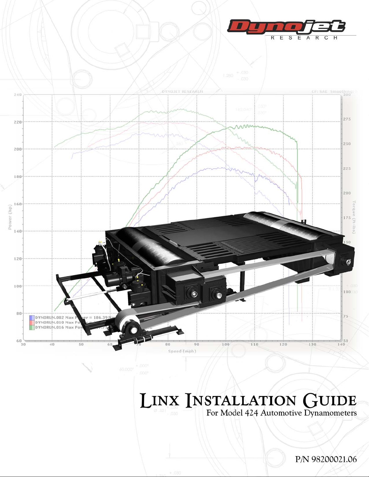
©2009-2013 Dynojet Research, Inc. All Rights Reserved.
Linx Installation for Model 424 Automotive Dynamometers
This manual is copyrighted by Dynojet Research, Inc., hereafter referred to as Dynojet,
and all rights are reserved. This manual, and the software described in it, is furnished
under license and may only be used or copied in accordance with the terms of such
license. This manual is furnished for informational use only, is subject to change without
notice, and should not be construed as a commitment by Dynojet. Dynojet assumes no
responsibility or liability for any error or inaccuracies that may appear in this manual.
Except as permitted by such license, no part of this manual may be reproduced, stored in
a retrieval system, or transmitted, in any form or by any means, electronic, mechanical,
recording, or otherwise, without the prior written permission of Dynojet.
The Dynojet logo is a trademark of Dynojet Research, Inc.
Any trademarks, trade names, service marks, or service names owned or registered by any
other company and used in this guide are the property of their respective companies.
Dynojet Research, Inc., 2191 Mendenhall Drive, North Las Vegas, Nevada 89081, USA.
Printed in USA.
Part Number: 98200021 Version 06 (05/2013)
Page 3

T
ABLE OF
C
ONTENTS
424 Linx Installation
Introduction . . . . . . . . . . . . . . . . . . . . . . . . . . . . . . . . . . . . . . . . . . . . . . . . . . . 2
Conventions Used In This Manual . . . . . . . . . . . . . . . . . . . . . . . . . . . . . . . . 2
Drill and Drill Bit Requirements . . . . . . . . . . . . . . . . . . . . . . . . . . . . . . . . . . 2
Technical Support . . . . . . . . . . . . . . . . . . . . . . . . . . . . . . . . . . . . . . . . . . . . 2
Linx Belt Drive Specifications . . . . . . . . . . . . . . . . . . . . . . . . . . . . . . . . . . . . . 3
Linx Belt Drive Specifications . . . . . . . . . . . . . . . . . . . . . . . . . . . . . . . . . . . . 3
Unpacking the Linx Parts . . . . . . . . . . . . . . . . . . . . . . . . . . . . . . . . . . . . . . . . 4
Dynojet Logo Panels and Pit Covers . . . . . . . . . . . . . . . . . . . . . . . . . . . . . . . 7
Removing the Dynojet Logo Panels—Above Ground . . . . . . . . . . . . . . . . . . 7
Removing the Pit Covers—In Ground . . . . . . . . . . . . . . . . . . . . . . . . . . . . . 9
Inner Mounting Plate Installation . . . . . . . . . . . . . . . . . . . . . . . . . . . . . . . . 10
Installing the Inner Mounting Plate—Moveable Dyno . . . . . . . . . . . . . . . . 10
Installing the Inner Mounting Plate—Stationary Dyno . . . . . . . . . . . . . . . . 12
Flange Bearing, Outer Shaft, and Splined Shaft Installation . . . . . . . . . . . 13
Drive Pulley Installation . . . . . . . . . . . . . . . . . . . . . . . . . . . . . . . . . . . . . . . . 15
Idler Pulley Assembly Installation . . . . . . . . . . . . . . . . . . . . . . . . . . . . . . . . . 17
Belt and Tensioner Pulley Assembly Installation . . . . . . . . . . . . . . . . . . . . . 18
Pulley Mounting Plates and Outer Bearings Installation . . . . . . . . . . . . . . 20
Installing the Idler Pulley Outer Bearing, Bearing Mounting Plate,
and Lower Pulley Mount . . . . . . . . . . . . . . . . . . . . . . . . . . . . . . . . . . . . . . 21
Installing the Moveable Dyno Pulley Outer Bearing, Bearing
Mounting Plate, and Lower Pulley Mount . . . . . . . . . . . . . . . . . . . . . . . . . 22
Installing the Upper Moveable Dyno and Idler Pulley Mounts . . . . . . . . . . 23
Installing the Stationary Dyno Pulley Outer Bearing, Bearing
Mounting Plate, and Lower Pulley Mount . . . . . . . . . . . . . . . . . . . . . . . . . 26
Installing the Upper Stationary Dyno Pulley Mount . . . . . . . . . . . . . . . . . . 27
Brake Signal Relay Installation . . . . . . . . . . . . . . . . . . . . . . . . . . . . . . . . . . . 29
Tension the Belt . . . . . . . . . . . . . . . . . . . . . . . . . . . . . . . . . . . . . . . . . . . . . . . 31
Above Ground Covers . . . . . . . . . . . . . . . . . . . . . . . . . . . . . . . . . . . . . . . . . 33
In Ground Covers . . . . . . . . . . . . . . . . . . . . . . . . . . . . . . . . . . . . . . . . . . . . . 37
Disconnect the Belt Drive from the Dyno Drums . . . . . . . . . . . . . . . . . . . . 41
Reconnecting the Belt Drive . . . . . . . . . . . . . . . . . . . . . . . . . . . . . . . . . . . . 42
Linx Installation for Model 424 Automotive Dynamometers
i
Page 4

TABLE OF CONTENTS
Appendix A Red Head Anchor Installation
Installation . . . . . . . . . . . . . . . . . . . . . . . . . . . . . . . . . . . . . . . . . . . . . . . . . . .A-2
Appendix B Disconnect the Belt Drive from the
Dyno Drums—Early Version Shafts
Disconnect the Belt Drive from the Dyno Drums . . . . . . . . . . . . . . . . . . .B-2
Appendix C Shaft Safety Wire Installation
Installation . . . . . . . . . . . . . . . . . . . . . . . . . . . . . . . . . . . . . . . . . . . . . . . . . . .C-2
ii
Linx Installation for Model 424 Automotive Dynamometers
Page 5

424 L
INX INSTALLATION
Thank you for your interest in Dynojet’s Automotive Dynamometers. Dynojet’s
software and dynamometers will give you the power to get the maximum
performance out of vehicles you evaluate. Whether you are new to the benefits of a
chassis dynamometer or an experienced performance leader, the repeatability and
diagnostic tools of WinPEP 7 software and a Dynojet dynamometer (dyno) will give
you the professional results you are looking for.
The Linx belt drive system synchronizes the speed of the front and rear drums for
testing sensitive all-wheel drive and two-wheel drive vehicles with traction control.
This document is designed to help you install the Linx system on your model 424
automotive dyno. To ensure safety and accuracy in the procedures, perform the
procedures as they are described.
Note: The Linx system is for 88-130-inch wheel base dynos only and cannot be
used with the extension kit.
Document Part Number: 98200021
Versio n 6
Last Updated: 05-30-13
This chapter is divided into the following categories:
•Introduction, page 2
• Linx Belt Drive Specifications, page 3
• Unpacking the Linx Parts, page 4
• Dynojet Logo Panels and Pit Covers, page 7
• Inner Mounting Plate Installation, page 10
• Flange Bearing, Outer Shaft, and Splined Shaft Installation, page 13
• Drive Pulley Installation, page 15
• Idler Pulley Assembly Installation, page 17
• Belt and Tensioner Pulley Assembly Installation, page 18
• Pulley Mounting Plates and Outer Bearings Installation, page 20
• Brake Signal Relay Installation, page 29
• Tension the Belt, page 31
• Above Ground Covers, page 33
• In Ground Covers, page 37
• Disconnect the Belt Drive from the Dyno Drums, page 41
Linx Installation for Model 424 Automotive Dynamometers
1
Page 6

424 LINX INSTALLATION
. . . . . . . . . . . . . . . . . . . . . . . . . . . . . . . . . . .
Introduction
INTRODUCTION
Thank you for your interest Dynojet’s Automotive Dynamometers. Before installing
the Linx system, please take a moment to read this guide for proper installation
procedures.
Note: The Linx system is for 88-130-inch wheel base dynos only and cannot be
used with the extension kit.
CONVENTIONS USED IN THIS MANUAL
The conventions used in this manual are designed to protect both the user and the
equipment.
example of convention description
The Caution icon indicates a potential hazard to the
dynamometer equipment. Follow all procedures
exactly as they are described and use care when
performing all procedures.
The Warning icon indicates potential harm to the
person performing a procedure and/or the
dynamometer equipment.
DRILL AND DRILL BIT REQUIREMENTS
You will need to provide a drill and drill bit capable of drilling holes in concrete. Refer
to Appendix A for more information on installing Red Head Anchors.
• drill bit size: 1/2-inch
• minimum hole depth: 1 5/8-inch (41.2 mm)
TECHNICAL SUPPORT
For assistance, please contact Dynojet Technical Support at 1-800-992-3525, e-mail
Dynojet at dynosales@dynojet.com, or write to Dynojet at 2191 Mendenhall Drive,
North Las Vegas, NV 89081.
Visit us on the World Wide Web at www.dynojet.com where Dynojet provides state of
the art technical support, on-line shopping, 3D visualizations, and press releases
about our latest product lines.
2
Linx Installation for Model 424 Automotive Dynamometers
Page 7
. . . . . . . . . . . . . . . . . . . . . . . . . . . . . . . . . . .
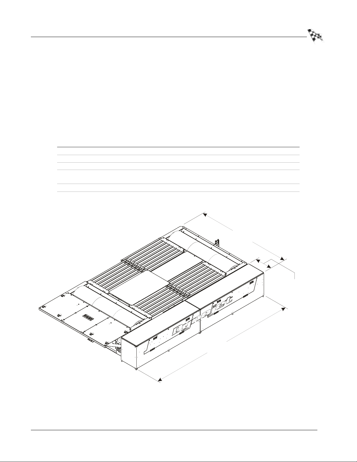
LINX BELT DRIVE SPECIFICATIONS
XD085
372.03 cm (146.46 in.)
frame, brake, and Linx option
441.96 cm (174.00 in.)
Linx option
50.80 cm (20.00 in.)
Linx option
The following specifications specific to the Linx belt drive dyno application will help
you set up your dyno area and verify you have met the requirements necessary to
operate your dyno safely.
For more detailed information about your dyno specifications, refer to the installation
guide included with your dyno.
LINX BELT DRIVE SPECIFICATIONS
description specifications
Length
of Linx option 441.96 cm (174.00 in.)
Width
of frame with eddy current brake and
Linx option
of Linx option 50.80 cm (20.00 in.)
Maximum Speed 290 kph (180 mph)
372.03 cm (146.46 in.)
424 LINX INSTALLATION
Linx Belt Drive Specifications
Version 6 Linx Installation for Model 424 Automotive Dynamometers
Figure 1: Above Ground Model 424xLC2 Dyno with Linx Belt Drive Dimensions
3
Page 8
424 LINX INSTALLATION
. . . . . . . . . . . . . . . . . . . . . . . . . . . . . . . . . . .
Unpacking the Linx Parts
UNPACKING THE LINX PARTS
Use the following steps to unload your Linx system parts.
1 Using a pry bar, or a large flat screwdriver, and a hammer, carefully remove the
top and sides of the crate. At this point, you will want to inspect the exterior of
the dyno for any indications of damage. Report any damage immediately.
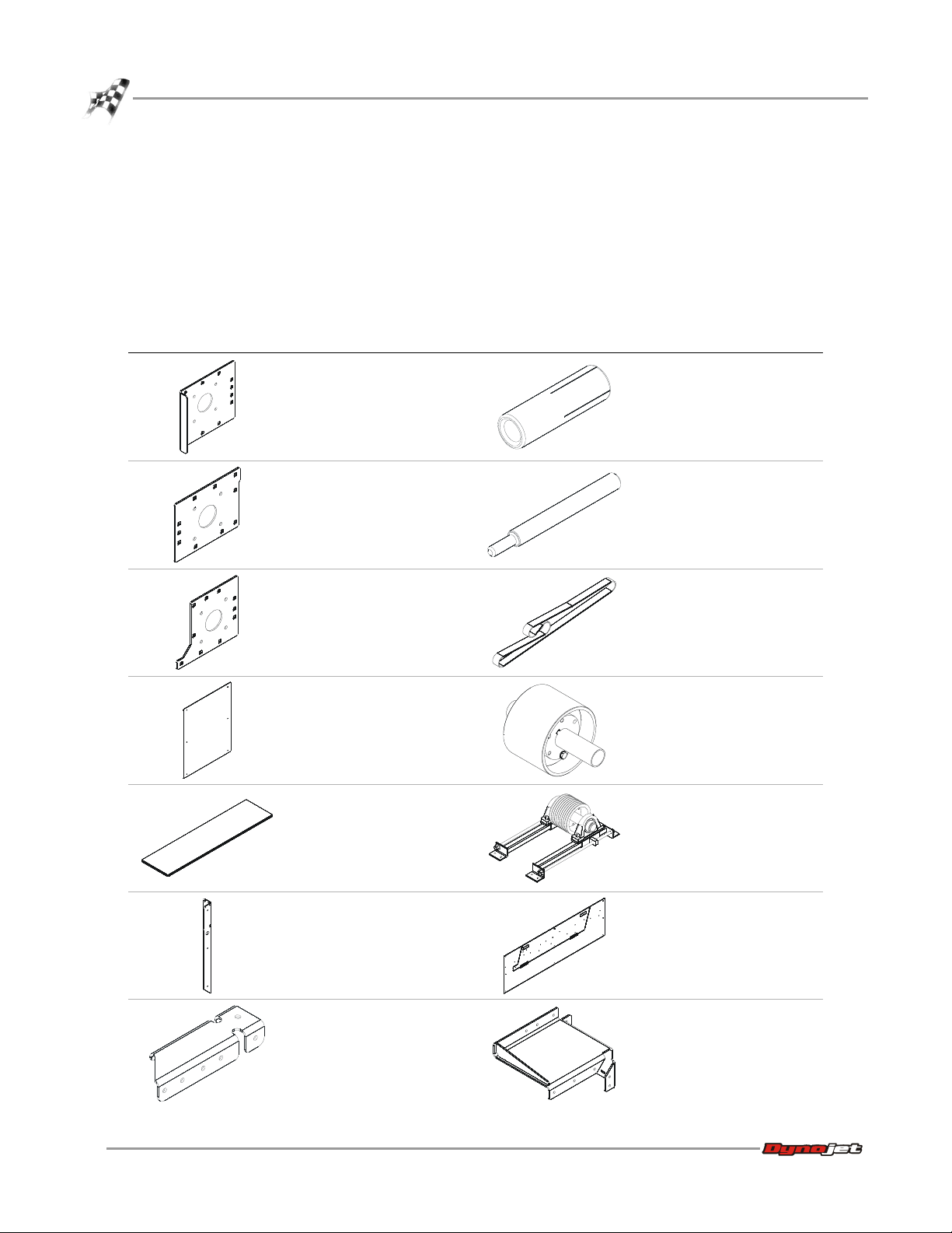
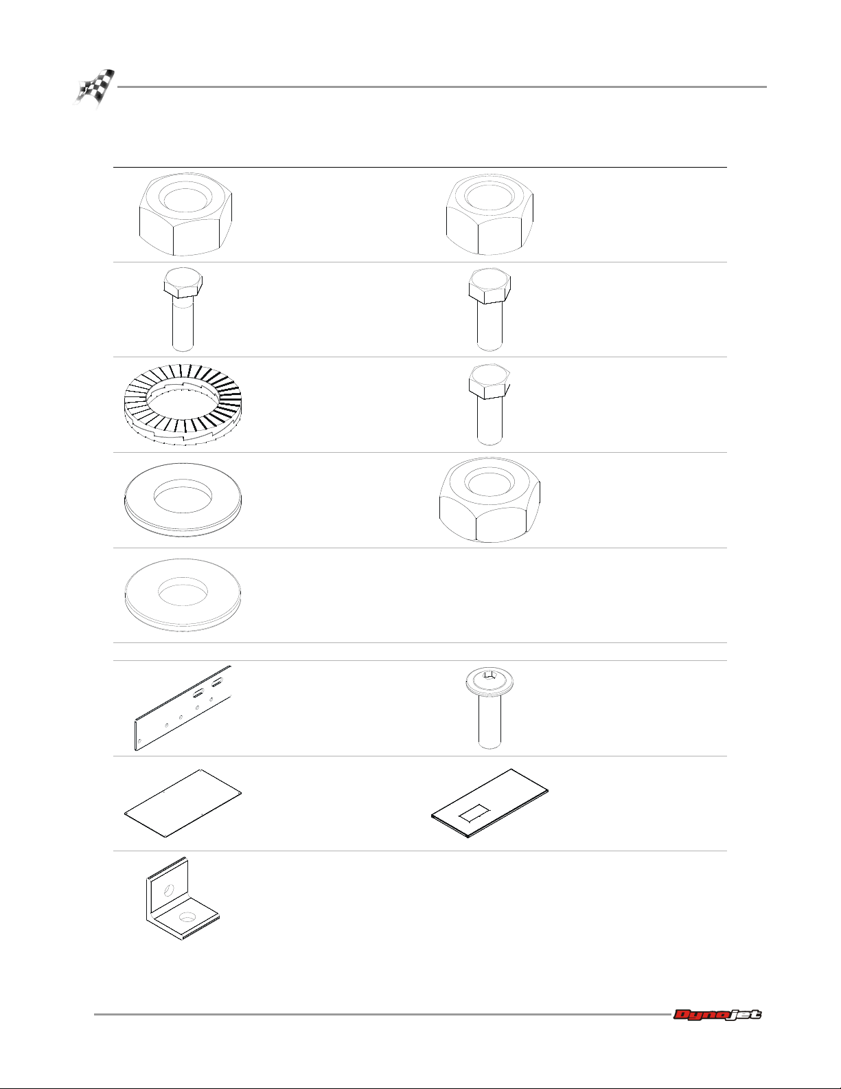
2 Remove the following parts from the crate and set aside.
part description part description
stationary pulley mounting
plate
P/N 21200083
anchor, red head, 3/8" (10
above ground, 6 additional
for in ground, plus 2 extra)
P/N 37513200
moveable pulley mounting
plate
P/N 21200090
idler pulley mounting plate
P/N 21200091
belt cover, end panel (2)
P/N 21200095
belt cover, top (2)
P/N 21200097
belt cover, leg (8)
P/N 21400006
installation tool, red head
anchor
P/N 37518200
v-belt 10/5V3800
P/N 46200007
idler pulley assembly
61100007
tensioner assembly
P/N 61100008
belt cover, front panel
assembly (2)
P/N 61100013
belt cover, center support
P/N 21600026
4
Linx Installation for Model 424 Automotive Dynamometers
upper stationary pulley
mount
P/N 61300022
Page 9
424 LINX INSTALLATION
Unpacking the Linx Parts
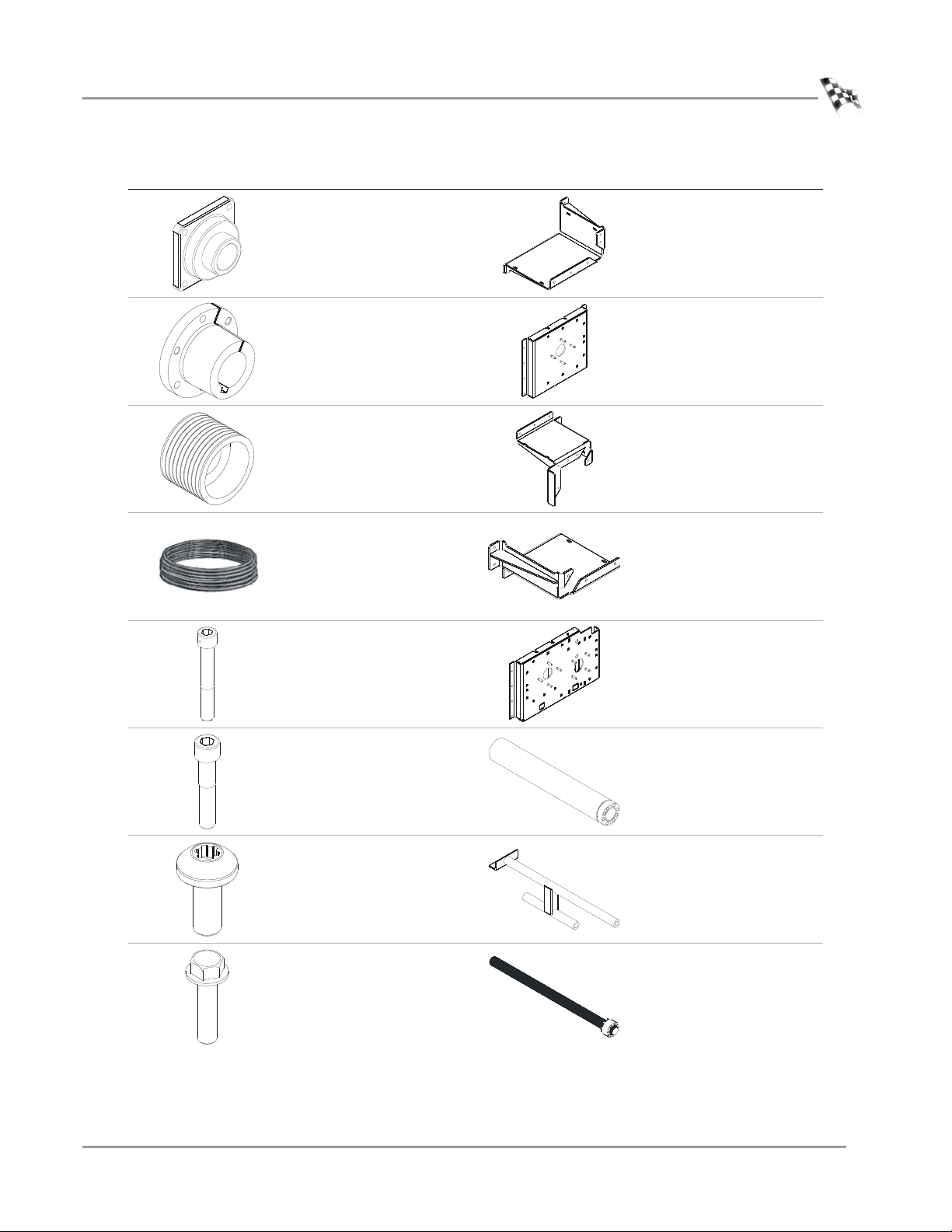
part description part description
flange bearing with lock
collar (6)
P/N 32300001
lower stationary pulley
mount (3)
P/N 61300023
bushing (2)
includes three bolts and
washers per bushing
P/N 32300002
grooved pulley (2)
P/N 32300003
safety wire
P/N 35300002
screw, 1/4-20 x 1.75",
shcs, drilled (4)
P/N 36500016
screw, 1/4-20 x 1.25",
shcs, drilled (4)
P/N 36500017
inner stationary dyno
mounting plate
P/N 61300024
upper moveable pulley
mount
P/N 61300025
lower moveable pulley
mount
P/N 61300026
inner moveable dyno
mounting plate
P/N 61300027
outer shaft, drive pulley (2)
P/N 61300030
screw, 1/4-20 x 5/8", panhead, torx, black (64 above
ground, 16 in ground)
P/N 36561045
bolt, 3/8-16 x 1.5", flangehex (2)
P/N 36582471
Version 6 Linx Installation for Model 424 Automotive Dynamometers
tension arm assembly
P/N 62100003
splined shaft (2)
P/N 62200006
5
Page 10
424 LINX INSTALLATION
Unpacking the Linx Parts
part description part description
nut, 9/16-12, hex (24)
P/N 36711100
nut, 3/8-16, hex (2)
P/N DM150-011-004
bolt, 9/16-12 x 2", hex (12)
P/N 36811640
washer, 1/4", lock (4)
P/N 36900001
washer, 3/8", hardened, flat
(86 above ground)
P/N 36923100
6 additional for in ground as
P/N DM150-011-002
washer, 9/16", flat (24)
P/N 36943101
The following parts are included in the In Ground Installation P/N 78100007:
pit cover mount
P/N 21200098
bolt, 3/8-16 x 1.25", hex (4)
included as extras
P/N DM150-011-006
bolt, 3/8-16 x 1", hex (85
above ground, 1 to de
couple the drums, 6
additional for in ground)
P/N DM150-019-012
nut, crush, 1/4-20 (8 above
ground, 4 in ground)
P/N DM150-020-005
bolt, 3/8-16 x 1/2", buttonhead flange allen, (8)
P/N 36580434
calibration access cover (2)
P/N 21217513
feet (6)
P/N 21919101
6
Linx Installation for Model 424 Automotive Dynamometers
pit cover assembly (2)
P/N 61329400
Page 11
. . . . . . . . . . . . . . . . . . . . . . . . . . . . . . . . . . .
DYNOJET LOGO PANELS AND PIT COVERS
XD001
logo panel
The Linx option can only be installed on one side of the dyno, refer to Figure 1. When
the Linx option is being installed on an existing above ground dyno, the Dynojet logo
panels must be removed. When the Linx option is being installed on an existing in
ground dyno, the pit covers must be removed.
If your Dynojet logo panels or pit covers are already removed, continue with “Inner
Mounting Plate Installation” on page 10.
424 LINX INSTALLATION
Dynojet Logo Panels and Pit Covers
REMOVING THE DYNOJET LOGO PANELS—ABOVE GROUND
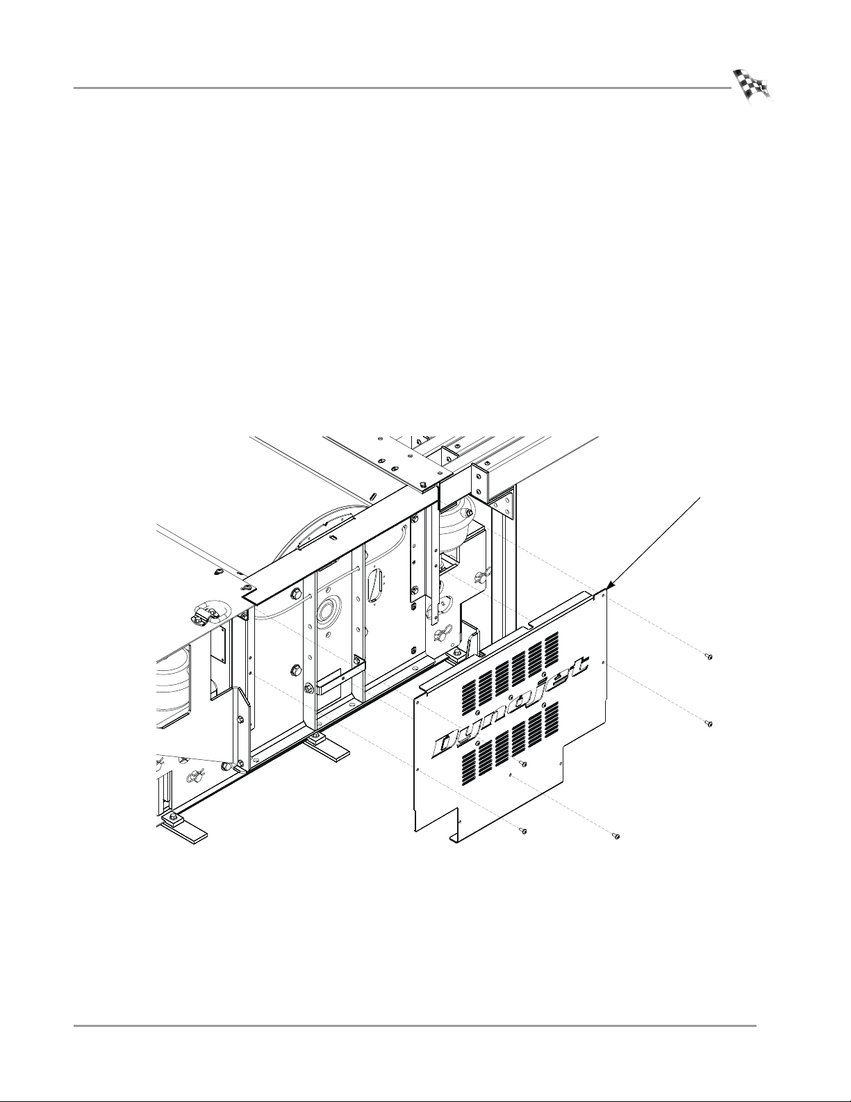
Repeat the following steps for each logo panel.
1 Remove the five 1/4-20 x 5/8-inch pan-head torx screws securing the logo panel to
the mounting brackets. Set these screws aside.
2 Remove the logo panel and set aside.
Figure 2: Remove the Dynojet Logo Panel
Version 6 Linx Installation for Model 424 Automotive Dynamometers
7
Page 12
424 LINX INSTALLATION
XD002
XD003
mounting bracket
lower mounting bracket
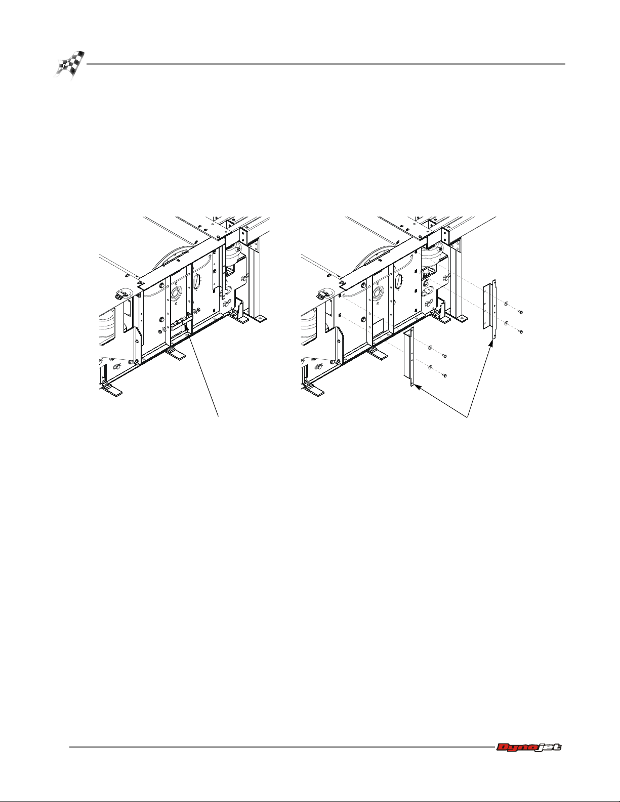
Dynojet Logo Panels and Pit Covers
3 Remove the two 7/16-14 x 1-inch hex bolts, two 7/16-inch flat washers, and two
7/16-14 nuts securing the lower mounting bracket to the dyno. Set the hardware
aside.
4 Remove the lower mounting bracket and set aside.
5 Remove the two 3/8-16 x 3/4-inch hex bolts and two 3/8-inch flat washers securing
each mounting bracket to the dyno. Set the hardware aside.
6 Remove each mounting bracket and set aside.
Figure 3: Remove the Logo Panel Mounting Brackets
8
Linx Installation for Model 424 Automotive Dynamometers
Page 13
424 LINX INSTALLATION
XD004
XD005
rear deck brace
mounting bracket
rear deck brace
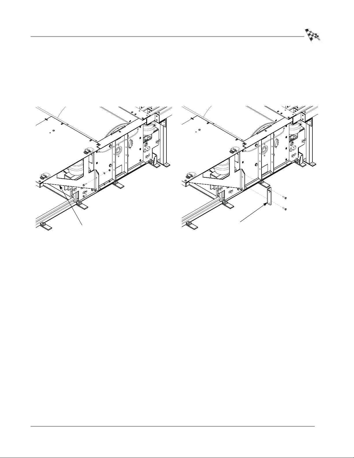
Dynojet Logo Panels and Pit Covers
7 Remove the two 3/8-16 x 1.5-inch flange hex bolts, washers, and nuts securing the
rear deck brace to the mounting bracket. Set the hardware aside.
8 Remove two 3/8-16 x 1.5-inch flange hex bolts securing the rear deck brace
mounting bracket to the dyno. Set the hardware aside.
9 Remove the rear deck brace mounting bracket and set aside.
Figure 4: Remove the Rear Deck Brace Mounting Bracket
REMOVING THE PIT COVERS—IN GROUND
If present, remove any pit covers on this side of the dyno.
Version 6 Linx Installation for Model 424 Automotive Dynamometers
9
Page 14
424 LINX INSTALLATION
. . . . . . . . . . . . . . . . . . . . . . . . . . . . . . . . . . .
XD006
for in ground
installations only
inner mounting plate
Inner Mounting Plate Installation
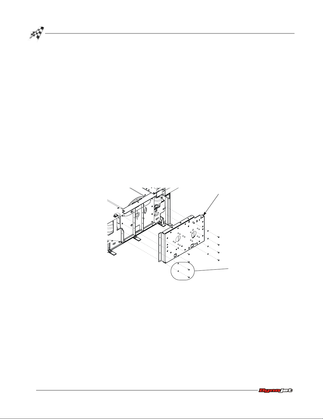
INNER MOUNTING PLATE INSTALLATION
Use the following instructions to install the moveable dyno and stationary dyno inner
mounting plates.
You will need the following parts:
• 36582471 Bolt, 3/8-16 x 1.5", Flange-Hex (2)
• 36923100 Washer, 3/8", Flat (18)
• 61300024 Inner Mounting Plate, Stationary Dyno
• 61300027 Inner Mounting Plate, Moveable Dyno
• DM150-011-004 Nut, 3/8-16, Hex (2)
• DM150-019-012 Bolt, 3/8-16 x 1", Hex (16)
INSTALLING THE INNER MOUNTING PLATE—MOVEABLE DYNO
1 Secure the inner mounting plate to the moveable dyno using eight 3/8 x 1-inch
bolts and eight 3/8-inch flat washers.
Note: For above ground installations, use only six 3/8 x 1-inch bolts and
six 3/8-inch flat washers.
Figure 5: Secure the Inner Mounting Plate to the Moveable Dyno
10
Linx Installation for Model 424 Automotive Dynamometers
Page 15
424 LINX INSTALLATION
XD007
access hole
XD008
XD009
rear deck brace
mounting bracket
rear deck brace
Inner Mounting Plate Installation
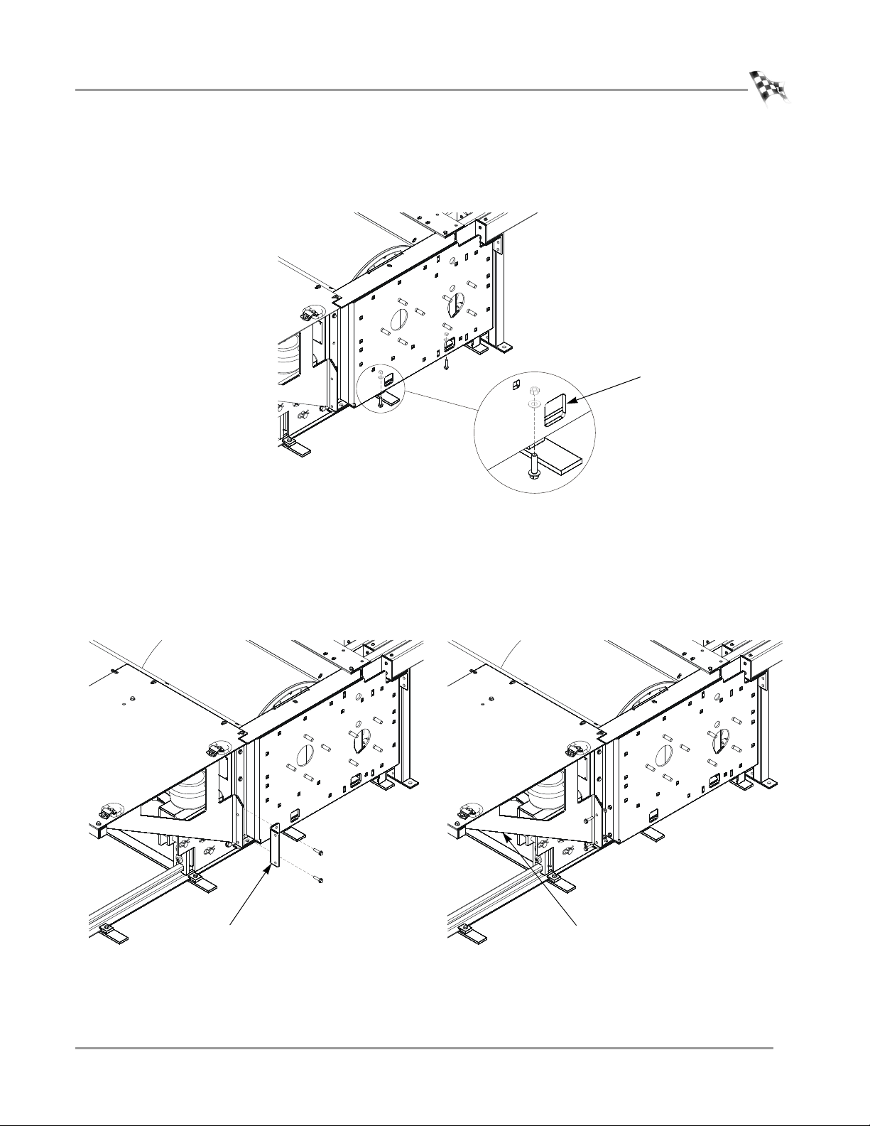
2 Using the access holes, secure the bottom of the inner mounting plate to the
moveable dyno using two 3/8-16 x 1.5-inch flange bolts, two 3/8-inch flat washers,
and two 3/8-inch nuts.
Figure 6: Secure the Bottom of the Inner Mounting Plate to the Moveable Dyno
The following steps are for the above ground dyno only.
3 Secure the rear deck brace mounting bracket to the inner mounting plate and
dyno using the two 3/8-16 x 1.5-inch flange-hex bolts removed earlier.
4 Secure the rear deck brace to the mounting bracket using the two
3/8-16 x 1.5-inch flange-hex bolts, washers, and nuts removed earlier.
Figure 7: Secure the Rear Deck Brace and Mounting Bracket
Version 6 Linx Installation for Model 424 Automotive Dynamometers
11
Page 16
424 LINX INSTALLATION
XD010
inner mounting plate
Inner Mounting Plate Installation
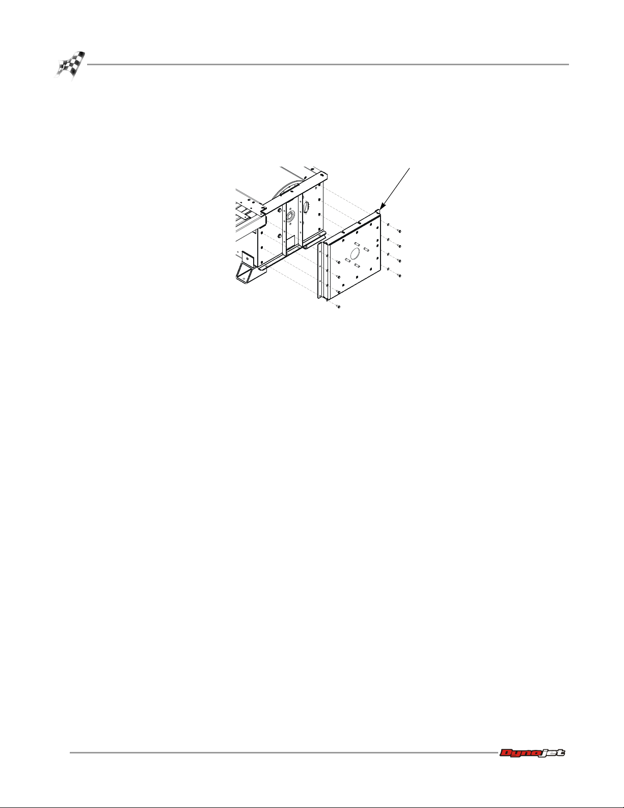
INSTALLING THE INNER MOUNTING PLATE—STATIONARY DYNO
Secure the inner mounting plate to the stationary dyno using eight 3/8 x 1-inch bolts
and eight 3/8-inch flat washers.
Figure 8: Secure the Inner Mounting Plate to the Stationary Dyno
12
Linx Installation for Model 424 Automotive Dynamometers
Page 17
424 LINX INSTALLATION
. . . . . . . . . . . . . . . . . . . . . . . . . . . . . . . . . . .
XD049
flange bearing
outer shaft
Flange Bearing, Outer Shaft, and Splined Shaft Installation
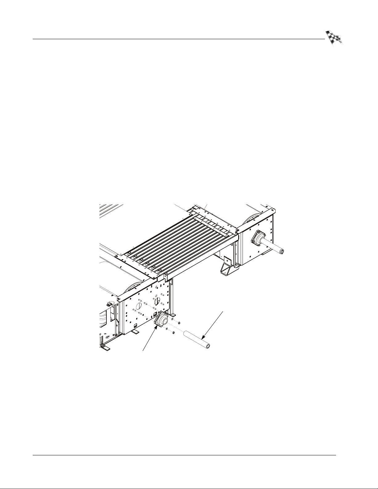
FLANGE BEARING, OUTER SHAFT, AND SPLINED SHAFT INSTALLATION
Use the following instructions to install the flange bearing, splined shaft, and outer
shaft on both the moveable and stationary dynos.
You will need the following parts:
• 32300001 Flange Bearing with Lock Collar (2)
• 36500016 Screw, 1/4-20 x 1.75", SHCS, Drilled (4)
• 36711100 Nut, 9/16-12, Hex (8)
• 36943101 Washer, 9/16", Flat (8)
• 61300030 Drive Pulley Shaft (Outer Shaft) (2)
• 62200006 Splined Shaft (2)
1 Place the flange bearing on the threaded studs on the inner plate.
2 Loosely secure the flange bearing to the inner plate using four 9/16-inch washers
and four 9/16-inch nuts.
3 Slide the outer shaft into the bearing.
Figure 9: Install the Flange Bearing and Outer Shaft
Version 6 Linx Installation for Model 424 Automotive Dynamometers
13
Page 18

424 LINX INSTALLATION
XD086
lock collar
threaded holes
splined shaft
unthreaded holes
outer shaft
splined shaft
flange
gap
16 1/8-inches
Flange Bearing, Outer Shaft, and Splined Shaft Installation
4 The distance from the face of the bearing mounting plate to the end of the outer
shaft should be approximately 16.125-inches.
5 Apply a small amount of grease to the first two inches of the splined shaft.
6 Slide the splined shaft through the outer shaft and into the splines in the dyno
drum.
7 Align the two unthreaded holes in the splined shaft flange with the two threaded
holes in the outer shaft.
8 Insert two 1/4-20 x 1.75-inch cap screws and tighten them just enough so the
tapered pins are engaged with the tapered holes.
Note: A gap will remain between the splined shaft flange and outer shaft.
9 While applying just enough upward pressure to support the shaft, tighten the
four 9/16-inch nuts.
10 Remove the two 1/4-20 x 1.75-inch cap screws.
11 Once the four 9/16-inch nuts are tight, it should be very easy to slide the splined
shaft in and out of the dyno splines.
12 Replace the 1/4-20 x 1.75-inch cap screws.
13 Confirm the outer shaft is 16 1/8-inches from the mounting plate.
14 Using the installation instructions included with the bearing, secure the lock
collar.
14
Linx Installation for Model 424 Automotive Dynamometers
Figure 10: Measure the Outer Shaft and Test Install the Splined Shaft
Page 19

. . . . . . . . . . . . . . . . . . . . . . . . . . . . . . . . . . .
DRIVE PULLEY INSTALLATION
grooved pulley
bushing
section view of bushing
and grooved pulley to
show correct alignment
with the tapered hole
XD051
bushing
grooved pulley
Use the following instructions to install the drive pulleys for both the moveable and
stationary dynos.
You will need the following parts:
• 32300002 Bushing (2)
includes three bolts and lock washers each
• 32300003 Grooved Pulley (2)
1 Place the bushing into the grooved pulley.
Figure 11: Align the Bushing in the Grooved Pulley
424 LINX INSTALLATION
Drive Pulley Installation
2 Loosely secure the bushing in the pulley using the three included bolts and lock
washers.
3 Slide the pulley assembly onto the outer shaft.
Figure 12: Install the Moveable Dyno Pulley Assembly
Version 6 Linx Installation for Model 424 Automotive Dynamometers
15
Page 20

424 LINX INSTALLATION
XD052
10-13/16 in. before tightening bolts
11.00 in. after tightening bolts
Drive Pulley Installation
4 The outer face of the pulley should be approximately 10-13/16 inches from the
face of the inner plate. Slowly tighten the bolts until the hub starts to pull into the
pulley, checking that it is approximately 10-13/16 inches from the inner plate
before the pulley is locked on the shaft.
5 Tighten the bolts by working around the bushing until none of the bolts will turn
at a torque wrench setting of 75 ft.-lb. The pulley should have moved out to
approximately 11 inches from the face of the inner plate.
Note: The measurement of 11 inches is not critical; however, this measurement
should be the same on both the moveable and stationary dynos.
Figure 13: Verify the Pulley Distance
16
Linx Installation for Model 424 Automotive Dynamometers
Page 21

. . . . . . . . . . . . . . . . . . . . . . . . . . . . . . . . . . .
IDLER PULLEY ASSEMBLY INSTALLATION
XD053
flange bearing
idler pulley assembly
You will need the following parts:
• 32300001 Flange Bearing with Lock Collar
• 36711100 Nut, 9/16-12, Hex (4)
• 36943101 Washer, 9/16", Flat (4)
• 61100007 Idler Pulley Assembly
1 Place the flange bearing on the threaded studs on the inner plate.
2 Secure the flange bearing to the inner plate using four 9/16-inch flat washers and
four 9/16-inch nuts.
3 Holding the idler assembly horizontal, slide the assembly into the bearing until its
outer edge is approximately 11-1/8-inches from the face of the inner plate.
4 Using the installation instructions included with the bearing, secure the lock
collar.
Note: Refer to the installation instructions included with the bearing.
Carefully allow the idler pulley assembly to hang in the bearing.
424 LINX INSTALLATION
Idler Pulley Assembly Installation
Figure 14: Install the Idler Pulley Assembly
Version 6 Linx Installation for Model 424 Automotive Dynamometers
17
Page 22

424 LINX INSTALLATION
. . . . . . . . . . . . . . . . . . . . . . . . . . . . . . . . . . .
Belt and Tensioner Pulley Assembly Installation
BELT AND TENSIONER PULLEY ASSEMBLY INSTALLATION
You will need the following parts:
• 36923100 Washer, 3/8", Flat (8)
• 37513200 Anchor, Red Head, 3/8" (8)
• 37518200 Red Head Anchor Installation Tool
• 46200006 Belt
• 61100008 Tensioner Assembly
• DM150-019-012 Bolt, 3/8-16 x 1", Hex (8)
Use the following instructions along with Figure 15 on page 19.
1 Route the belt around the pulleys as shown in Figure 15 on page 19.
2 Place the belt around the tensioner pulley and place the tensioner assembly in the
position shown.
Note: Verify the welded on nuts on the tensioner assembly are towards the back
and the tensioner pulley is slid all the way to the end of the assembly towards the
stationary dyno.
3 Verify the bearings are the same distance from each mounting angle.
4 Slide the tensioner assembly on the floor as far back as possible, taking some slack
out of the belt.
Note: Do not tension the belt at this point.
5 Using a long straight edge, verify the tensioner pulley and the movable dyno
pulley are aligned.
6 With the tensioner assembly in this position, drill the eight holes needed to
secure the tensioner assembly to the floor.
7 Install eight Red Head anchors. Refer to Appendix A for installation instructions.
8 Secure the tensioner assembly to the floor using eight 3/8-16 x 1-inch bolts and
eight 3/8-inch flat washers.
Note: If a Red Head is drilled too deep, use one of the four 3/8 x 1.25-inch bolts
included. Two extra Red Heads are also included.
9 Apply some grease to the two ACME threads.
18
Linx Installation for Model 424 Automotive Dynamometers
Page 23

424 LINX INSTALLATION
XD054
tensioner pulley towards
stationary dyno
welded nuts towards back
apply grease to
ACME threads
Belt and Tensioner Pulley Assembly Installation
Figure 15: Install the Belt and Tensioner Pulley Assembly
Version 6 Linx Installation for Model 424 Automotive Dynamometers
19
Page 24

424 LINX INSTALLATION
. . . . . . . . . . . . . . . . . . . . . . . . . . . . . . . . . . .
Pulley Mounting Plates and Outer Bearings Installation
PULLEY MOUNTING PLATES AND OUTER BEARINGS INSTALLATION
Note: The inner pulley mounting plates and the pulley mounts are stamped with
numbers to help match the parts and guide you in the installation process.
You will need the following parts:
• 21200083 Stationary Dyno Pulley Bearing Mounting Plate
• 21200090 Moveable Dyno Pulley Bearing Mounting Plate
• 21200091 Idler Pulley Bearing Mounting Plate
• 32300001 Flange Bearing with Lock Collar (3)
• 36711100 Nut, 9/16-12, Hex (12)
• 36811640 Bolt, 9/16-12 x 2", Hex (12)
• 36900001 Washer, 1/4", Lock (4)
• 36923100 Washer, 3/8", Flat (60)
• 36943101 Washer, 9/16", Flat (12)
• 61300022 Pulley Mount, Upper, Stationary Dyno
• 61300023 Pulley Mount, Lower, Stationary Dyno (3)
used for stationary dyno pulley, lower
moveable dyno pulley, upper
idler pulley, lower
• 61300025 Pulley Mount, Upper, Idler Pulley
• 61300026 Pulley Mount, Lower, Moveable Dyno
• DM150-019-012 Bolt, 3/8-16 x 1", Hex (60)
20
Linx Installation for Model 424 Automotive Dynamometers
Page 25

424 LINX INSTALLATION
XD055
outer idler
bearing
idler bearing
plate
XD056
pulley mount
P/N 61300023
idler bearing plate
Pulley Mounting Plates and Outer Bearings Installation
INSTALLING THE IDLER PULLEY OUTER BEARING, BEARING MOUNTING PLATE, AND LOWER PULLEY MOUNT
1 Secure the outer idler bearing to the idler bearing mounting plate using four
9/16-12 x 2-inch bolts, four 9/16-inch flat washers, and four 9/16-inch nuts. Slide
this assembly onto the idler shaft.
Figure 16: Install the Outer Idler Pulley Bearing and Bearing Mounting Plate
2 Place a lower stationary dyno pulley mount (P/N 61300023) under the idler pulley
and loosely secure the mount to the inner plate using five 3/8-16 x 1-inch bolts
and five 3/8-inch flat washers (one of the holes in the pulley mount is not used).
3 Loosely secure the pulley mount to the idler bearing mounting plate using
five 3/8-16 x 1-inch bolts and five 3/8-inch flat washers.
4 Before tightening these bolts, align the idler with the moveable dyno pulley.
With a straight edge on the idler pulley there should be a even gap of about
1/8-inch to the moveable dyno pulley.
5 Tighten all the bolts.
Figure 17: Secure the Pulley Mount Under the Idler Pulley
Version 6 Linx Installation for Model 424 Automotive Dynamometers
21
Page 26

424 LINX INSTALLATION
XD057
moveable dyno
puller bearing
moveable dyno pulley
bearing plate
moveable dyno
pulley
XD058
pulley mount
P/N 61300026
Pulley Mounting Plates and Outer Bearings Installation
INSTALLING THE MOVEABLE DYNO PULLEY OUTER BEARING, BEARING MOUNTING PLATE,
AND LOWER PULLEY MOUNT
1 Secure the outer moveable dyno pulley bearing to the moveable dyno pulley
bearing plate using four 9/16-12 x 2-inch bolts, four 9/16-inch flat washers, and
four 9/16-inch nuts. Slide this assembly onto the moveable dyno pulley outer
shaft.
Figure 18: Install the Outer Moveable Dyno Pulley Bearing and Bearing Plate
2 Place the lower moveable dyno pulley mount (P/N 61300026) under the
moveable dyno pulley and loosely secure the mount to the inner plate using
five 3/8-16 x 1-inch bolts and five 3/8-inch flat washers.
3 Loosely secure the pulley mount to the moveable dyno pulley bearing plate using
three 3/8-16 x 1-inch bolts and three 3/8-inch flat washers.
Figure 19: Secure the Pulley Mount Under the Moveable Dyno Pulley
22
Linx Installation for Model 424 Automotive Dynamometers
Page 27

424 LINX INSTALLATION
XD059
pulley mount
P/N 61300023
Pulley Mounting Plates and Outer Bearings Installation
INSTALLING THE UPPER MOVEABLE DYNO AND IDLER PULLEY MOUNTS
1 Place a lower stationary dyno pulley mount (P/N 61300023) over the moveable
dyno pulley and loosely secure the mount to the inner plate using
five 3/8-16 x 1-inch bolts and five 3/8-inch flat washers (one of the holes in the
pulley mount is not used).
2 Loosely secure the pulley mount to the moveable dyno pulley bearing plate using
five 3/8-16 x 1-inch bolts and five 3/8-inch flat washers.
Figure 20: Secure the Pulley Mount Over the Moveable Dyno Pulley
Version 6 Linx Installation for Model 424 Automotive Dynamometers
23
Page 28

424 LINX INSTALLATION
XD060
pulley mount
P/N 61300025
Pulley Mounting Plates and Outer Bearings Installation
3 Place the upper moveable dyno pulley mount (P/N 61300025) over the idler
pulley and loosely secure the mount to the inner plate using five 3/8-16 x 1-inch
bolts and five 3/8-inch flat washers.
4 Loosely secure the pulley mount to the idler pulley bearing plate using
five 3/8-16 x 1-inch bolts and five 3/8-inch flat washers.
5 Loosely secure the pulley mount to the movable dyno pulley bearing plate using
two 3/8-16 x 1-inch bolts and two 3/8-inch flat washers.
6 While applying upward pressure to support the shaft and pulley, tighten all the
bolts.
Figure 21: Secure the Pulley Mount Over the Idler Pulley
24
Linx Installation for Model 424 Automotive Dynamometers
Page 29

424 LINX INSTALLATION
XD068
lock washer
serrated edges
facing outward
lock washer
cap screw
Pulley Mounting Plates and Outer Bearings Installation
7 Remove the 1/4-20 x 1.75-inch cap screws from the splined shaft.
8 Verify the splined shaft will slide in and out of the dyno splines easily once all the
bolts are tightened.
Note: The splined shaft must easily slide in and out of the dyno splines in order
to engage and disengage the Linx belt drive.
9 Using the installation instructions included with the bearing, secure the lock
collars of both bearings.
10 Using two 1/4-inch lock washers, replace the 1/4-20 x 1.75-inch cap screws.
11 Tighten the 1/4-20 x 1.75-inch cap screws to 7 ft.-lb. (9.5Nm).
Note: A gap will remain between the splined shaft flange and outer shaft.
Note: The lock washer is comprised of two individual pieces. Should the washer
separate, verify the pieces go back together with the serrated edges facing
outward as shown in Figure 22.
12 Secure the cap screws with the shaft safety wire. Refer to Appendix C for
installation instructions.
Failure to secure the cap screws with safety wire can result in damage to the
dyno and/or the vehicle.
Figure 22: Install the Cap Screws and Lock Washers
Version 6 Linx Installation for Model 424 Automotive Dynamometers
25
Page 30

424 LINX INSTALLATION
XD061
stationary dyno
pulley bearing
stationary dyno
pulley bearing plate
stationary dyno
pulley
XD062
pulley mount
P/N61300023
stationary dyno
pulley bearing plate
Pulley Mounting Plates and Outer Bearings Installation
INSTALLING THE STATIONARY DYNO PULLEY OUTER BEARING, BEARING MOUNTING PLATE,
AND LOWER PULLEY MOUNT
1 Secure the outer stationary dyno pulley bearing to the stationary dyno pulley
bearing plate using four 9/16-12 x 2-inch bolts, four 9/16-inch flat washers, and
four 9-16-inch nuts. Slide this assembly onto the stationary dyno pulley outer
shaft.
Figure 23: Install the Outer Stationary Dyno Pulley Bearing and Bearing Plate
2 Place a lower stationary dyno pulley mount (P/N 61300023) under the stationary
dyno pulley and loosely secure the mount to the inner plate using
five 3/8-16 x 1-inch bolts and five 3/8-inch flat washers (one of the holes on the
pulley mount is not used).
3 Loosely secure the pulley mount to the stationary dyno pulley bearing plate using
five 3/8-16 x 1-inch bolts and five 3/8-inch flat washers.
Figure 24: Secure the Pulley Mount Under the Stationary Dyno Pulley
26
Linx Installation for Model 424 Automotive Dynamometers
Page 31

Pulley Mounting Plates and Outer Bearings Installation
XD063
pulley mount
P/N 61300022
INSTALLING THE UPPER STATIONARY DYNO PULLEY MOUNT
1 Place the upper stationary dyno pulley mount (P/N 61300022) over the stationary
dyno pulley and loosely secure the mount to the inner plate using
five 3/8-16 x 1-inch bolts and five 3/8-inch flat washers (one of the holes on the
pulley mount is not used).
2 Loosely secure the pulley mount to the stationary dyno pulley bearing plate using
five 3/8-16 x 1-inch bolts and five 3/8-inch flat washers.
3 While applying upward pressure to support the shaft and pulley, tighten all the
bolts.
424 LINX INSTALLATION
Figure 25: Secure the Pulley Mount Over the Stationary Dyno Pulley
Version 6 Linx Installation for Model 424 Automotive Dynamometers
27
Page 32

424 LINX INSTALLATION
XD069
lock washer
serrated edges
facing outward
lock washer
cap screw
Pulley Mounting Plates and Outer Bearings Installation
4 Remove the 1/4-20 x 1.75-inch cap screws from the splined shaft.
5 Verify the splined shaft will slide in and out of the dyno splines easily once all the
bolts are tightened.
Note: The splined shaft must easily slide in and out of the dyno splines in order
to engage and disengage the Linx belt drive.
6 Using the installation instructions included with the bearing, secure the lock
collars of the bearing.
7 Using two 1/4-inch lock washers, replace the 1/4-20 x 1.75-inch cap screws.
8 Tighten the 1/4-20 x 1.75-inch cap screws to 7 ft.-lb. (9.5Nm).
Note: A gap will remain between the splined shaft flange and outer shaft.
Note: The lock washer is comprised of two individual pieces. Should the washer
separate, verify the pieces go back together with the serrated edges facing
outward as shown in Figure 26.
9 Secure the cap screws with the shaft safety wire. Refer to Appendix C for
installation instructions.
Failure to secure the cap screws with safety wire can result in damage to the
dyno and/or the vehicle.
28
Linx Installation for Model 424 Automotive Dynamometers
Figure 26: Install the Cap Screws and Lock Washers
Page 33

. . . . . . . . . . . . . . . . . . . . . . . . . . . . . . . . . . .
BRAKE SIGNAL RELAY INSTALLATION
Use the following instructions along with Figure 27 on page 30 if you are upgrading
an existing dyno. If you are installing a new dyno, skip these instructions and
continue with “Tension the Belt” on page 31.
1 Disconnect the 4WD power supply.
2 Turn off the power to the dyno electronics.
3 Remove the two brake signal wires from the terminal labeled BRK IN on the 4WD
board.
4 Cut off the ferrules and strip the wires.
5 Attach the butt connector from the relay 85 to the yellow brake signal wire.
6 Attach the butt connector from the relay 86 to the black brake signal wire.
7 Remove the black and white power wires from the terminal labeled GND and +12
on the 4WD board.
8 Cut off the ferrules and strip the wires.
9 Attach the butt connector from the white jumper wire to the white power wire.
10 Insert one of the ferrules from the white jumper wire to the BRK IN terminal and
secure.
11 Insert the other ferrule from the white jumper wire to the +12 terminal and
secure.
12 Attach the butt connector from the relay 30 to the black power wire.
13 Insert the ferrule from the relay 30 wire to the GND terminal and secure.
14 Attach the yellow wire from the relay 87a to the open BRK IN terminal.
15 Secure the relay to the 4WD board using an existing nut.
16 Reconnect the 4WD power supply.
17 Turn on the power to the dyno electronics.
18 Wheelbase adjustment may now be performed only with the dyno brakes
released.
424 LINX INSTALLATION
Brake Signal Relay Installation
Version 6 Linx Installation for Model 424 Automotive Dynamometers
29
Page 34

424 LINX INSTALLATION
drumbrakefromB.O.B.
powersupply
movementswitch
railbrakepressureswitch
BLK
WHT
BLK
WHT
RED
YEL
YEL
BLK
BLK
WHT
YEL
CB024
secure relay to 4WD
board using existing nut
Brake Signal Relay Installation
Figure 27: Install the Brake Signal Relay
30
Linx Installation for Model 424 Automotive Dynamometers
Page 35

. . . . . . . . . . . . . . . . . . . . . . . . . . . . . . . . . . .
TENSION THE BELT
You will need the following part:
• 62100003 Tension Arm Assembly
Use the following instructions along with Figure 28 on page 32.
1 Verify the drum brakes are released.
424 LINX INSTALLATION
Tension the Belt
The dyno wheel base should only be adjusted with the brakes released or the
Linx belt drive system disengaged.
2 Set the dyno to a wheelbase adjustment of 101-inches.
3 Measure 50.5-inches from the center of one of the drums. Mark this point on the
bridge tube closest to the belt.
4 Loosen the ACME lock nuts on the tensioner.
Note: Before tensioning the belt, the brakes must be released and the drums free
to turn.
5 Turn the ACME screws on the tensioner to tension the belt. Alternate sides to
keep the pulley aligned with the belt.
6 Once the belt has some tension, place the tension arm centered on the mark.
Verify the angle is completely seated on the underside of the tube.
7 Place two weights on the tension arm with the outer weight flush with the end of
the arm. If the weights want to slip off of the bar, tension the belt more before
putting the weights on.
Note: Use the weights included in the Eddy Current Brake calibration set.
8 With the weights placed on the bar, tension the belt until the tension bar is
horizontal.
9 Place a straight edge on the side of the tensioner pulley so it runs parallel to the
belt. Verify the distance between the straight edge and the edge of the belt is even.
Adjust this distance by turning one of the ACME screws if necessary.
10 Tighten the lock nuts.
11 Remove the weights and the tension arm.
12 Recheck the belt tension after the first several dyno runs and occasionally after
that.
Version 6 Linx Installation for Model 424 Automotive Dynamometers
31
Page 36

424 LINX INSTALLATION
XD088
mark 50.50 in. from center of drum
angle on underside of bridge tube
lock nuts
tension arm
weights
ACME screws
Tension the Belt
Figure 28: Tension the Belt
32
Linx Installation for Model 424 Automotive Dynamometers
Page 37

. . . . . . . . . . . . . . . . . . . . . . . . . . . . . . . . . . .
ABOVE GROUND COVERS
XD090
end panel
You will need the following parts:
• 21200095 Belt Cover, End Panel (2)
• 21200097 Belt Cover, Top (2)
• 21400006 Belt Cover, Leg (8)
• 21600026 Belt Cover, Center Support
• 36561045 Screw, 1/4-20 x 5/8", Pan-Head, Torx (64)
• 61100013 Belt Cover, Front Panel Assembly (2)
• DM150-020-005 Nut-Crush, 1/4-20 (8)
1 Place the tops flange side up on the floor.
2 Secure two legs in the corners of each top as shown using four 1/4-20 x 5/8-inch
torx screws each.
3 Secure one leg in the middle of each top as shown using two 1/4-20 x 5/8-inch
torx screws each.
4 Secure one leg in the corner of each top as shown using two 1/4-20 x 5/8-inch torx
screws each.
5 Secure each end panel using six 1/4-20 x 5/8-inch torx screws.
424 LINX INSTALLATION
Above Ground Covers
Figure 29: Install the Legs and End Panels
Version 6 Linx Installation for Model 424 Automotive Dynamometers
33
Page 38

424 LINX INSTALLATION
XD091
center support
center support included with
wheelbase extension kit
Above Ground Covers
6 Secure the two tops together using two 1/4-20 x 5/8-inch torx screws and two
1/4-20 nuts each.
7 Secure the center support to the tops using four 1/4-20 x 5/8-inch torx screws and
four 1/4-20 nuts.
Note: When the dyno is equipped with the wheelbase extension kit
(P/N 61119183), use the center support (P/N 21200176) included in the kit.
Figure 30: Secure the Tops Together and Install the Center Support
34
Linx Installation for Model 424 Automotive Dynamometers
Page 39

424 LINX INSTALLATION
XD093
center support
Above Ground Covers
8 Remove the 1/4-20 x 5/8-inch torx screw from the outer most tube of the dyno
bridge.
9 Turn the cover assembly over and move towards the dyno. Place the cover so the
center support is on the outer tube with the hole lined up as shown.
10 Secure the cover assembly to the dyno using the 1/4-20 x 5/8-inch torx screw
removed earlier.
Figure 31: Secure the Cover Assembly to the Dyno
Version 6 Linx Installation for Model 424 Automotive Dynamometers
35
Page 40

424 LINX INSTALLATION
XD094
Above Ground Covers
11 Secure each side panel to the cover assembly using seven 1/4-20 x 5/8-inch torx
screws.
Figure 32: Secure the Side Panels to the Cover Assembly
36
Linx Installation for Model 424 Automotive Dynamometers
Page 41

. . . . . . . . . . . . . . . . . . . . . . . . . . . . . . . . . . .
IN GROUND COVERS
pit cover mount
center support
pit cover mount
center support
center support included with
wheelbase extension kit
You will need the following parts:
• 21200098 Pit Cover Mount
• 21217513 Calibration Access Cover (2)
• 21600026 Belt Cover, Center Support
• 21919101 Feet, Pit Cover (6)
• 36561045 Screw, 1/4-20 x 5/8", Pan-Head, Torx (16)
• 36580434 Bolt, 3/8-16 x 1/2" Button-Head Flange, Allen (8)
• 36923100 Washer, 3/8", Flat (6)
• 37513200 Anchor, Red Head, 3/8" (6)
• 37518200 Red Head Anchor Installation Tool
• 61329400 Pit Retarder Cover Assembly (2)
• DM150-019-012 Bolt, 3/8-16 x 1", Hex (6)
• DM150-020-005 Nut-Crush, 1/4-20 (4)
1 Secure the center support to the pit cover mount using four 1/4-20 x 5/8-inch torx
screws and four 1/4-20 nuts.
Note: When the dyno is equipped with the wheelbase extension kit
(P/N 61119183), use the center support (P/N 21200176) included in the kit.
424 LINX INSTALLATION
In Ground Covers
Figure 33: Secure the Center Support to the Pit Cover Mount
Version 6 Linx Installation for Model 424 Automotive Dynamometers
37
Page 42

424 LINX INSTALLATION
XD096
center support
assembly
In Ground Covers
2 Remove the 1/4-20 x 5/8-inch torx screw from the outer most tube of the dyno
bridge.
3 Secure the center support assembly to the outer bridge tube using the screw
removed earlier.
Figure 34: Secure the Center Support to the Dyno
38
Linx Installation for Model 424 Automotive Dynamometers
Page 43

424 LINX INSTALLATION
XD097
In Ground Covers
4 Place the pit cover assemblies on the floor in the position shown.
5 Secure the covers to the center support using two 3/8-16 x 1/2-inch button-head
flange bolts.
Figure 35: Secure the Pit Cover Assemblies to the Center Support
Version 6 Linx Installation for Model 424 Automotive Dynamometers
39
Page 44

424 LINX INSTALLATION
XD037
access cover
In Ground Covers
6 Secure the six angle feet to the pit cover assemblies in the positions shown using
one 3/8-16 x 1/2-inch button-head flange bolt each.
7 Using the feet as a template, drill each hole needed to secure the feet to the floor.
8 Install the six Red Head anchors. Refer to Appendix A for installation instructions.
9 Secure each foot to the floor using one 3/8-16 x 1-inch hex bolt and one 3/8-inch
washer.
10 Secure one access cover to each pit cover assembly using six 1/4-20 x 5/8-inch torx
screws each.
40
Figure 36: Install the Pit Cover Feet and Access Covers
Linx Installation for Model 424 Automotive Dynamometers
Page 45

424 LINX INSTALLATION
. . . . . . . . . . . . . . . . . . . . . . . . . . . . . . . . . . .
XD084
threaded holes
Disconnect the Belt Drive from the Dyno Drums
DISCONNECT THE BELT DRIVE FROM THE DYNO DRUMS
The Linx belt can be disengaged by pulling the splined shafts out of the dyno splines.
1 Loosen the three finger screws and lower the access panel.
For in ground dynos, remove the six 1/4-20 x 5/8-inch torx screws securing each
access cover and set aside. Remove each access cover and set aside.
2 Remove the two 1/4-20 x 1.75-inch cap screws and two 1/4-inch lock washers from
each shaft.
3 Thread the 1/4-20 x 1.25-inch cap screws into the threaded holes on the splined
shaft flange.
4 Tighten the cap screws until the tapered pins disengage from the tapered holes.
5 At each drum, pull the splined shaft out at least four inches.
Always disengage the belt drive at BOTH dynos.
Figure 37: Disconnect the Belt Drive from the Dyno Drums
Version 6 Linx Installation for Model 424 Automotive Dynamometers
41
Page 46

424 LINX INSTALLATION
Disconnect the Belt Drive from the Dyno Drums
RECONNECTING THE BELT DRIVE
1 Remove the 1/4-20 x 1.25-inch cap screws from the threaded holes in the splined
shaft.
2 Slide the shaft into the dyno drum aligning the two unthreaded holes in the
splined shaft flange with the two threaded holes in the outer shaft.
3 Install the 1/4-20 x 1.75-inch cap screws and 1/4-inch lock washers and torque to
7 ft.-lb. (9.5Nm).
4 Secure the cap screws with the shaft safety wire. Refer to Appendix C for
installation instructions.
Failure to secure the cap screws with safety wire can result in damage to the
dyno and/or the vehicle
42
Linx Installation for Model 424 Automotive Dynamometers
Page 47

R
ED
H
EAD
A PPENDIX
A
A
NCHOR INSTALLATION
This appendix contains instructions for installing the Red Head Multi-Set™II Anchors.
The anchors will be used to secure the dyno to concrete. To ensure safety and
accuracy in the procedures, perform the procedures as they are described. Be sure to
read and understand the warnings included in this appendix.
WARNINGS
Always wear safety glasses and other necessary protective devices or apparel
when installing or working with anchors.
ITW Ramset/Red Head Multi-Set II Anchors are designed to operate properly
only when installed with ITW Ramset/Red Head brand Setting Tools.
The use of a 24 to 40 ounce hammer is recommended for expanding Multi-Set II
anchors.
The use of carbide drill bits manufactured with ANSI B94. 12-77 drill bit diameter
requirements is recommended for installation of this anchor.
Not recommended for use in lightweight masonry material such as block or brick.
Use of core drills is not recommended to drill holes for use with this anchor.
Not recommended for use in new concrete which has not had sufficient time to cure.
Anchor spacing and edge distance requirements (anchor installation locations) are
the responsibility of the engineer of record.
CONTACT INFORMATION FOR ITW RAMSET/RED HEAD
Contact ITW Ramset/Red Head at 1-630-350-0370, or 1300 North Michael Drive,
Wood Dale, IL 60191.
Linx Installation for Model 424 Automotive Dynamometers
A-1
Page 48

APPENDIX A
. . . . . . . . . . . . . . . . . . . . . . . . . . . . . . . . . . .
anchor
Installation
INSTALLATION
Use the table below to determine the catalog number, drill bit size, minimum hole
depth, and setting tool catalog number.
catalog number drill bit size minimum hole depth
Carbon Steel
RM-38/RL-38 (9.5 mm)
Use the following instructions to install the Red Head anchors.
1 Drill the hole in the concrete the same outside diameter as the anchor being used
to any depth exceeding minimum embedment.
setting tool
catalog number
1/2-inch 1 5/8-inch (41.2 mm) RT-138
Figure A-1: Red Head Anchor—Drill the Hole
2 Insert the anchor.
Figure A-2: Red Head Anchor—Insert the Anchor
A-2
Linx Installation for Model 424 Automotive Dynamometers
Page 49

RED HEAD ANCHOR INSTALLATION
setting tool
Installation
3 Using a hammer, drive the anchor flush with the surface of the concrete, or below
the surface if the hole depth exceeds minimum embedment.
Figure A-3: Red Head Anchor—Drive the Anchor Flush
4 Using a hammer, expand the anchor with the setting tool. The anchor is properly
expanded when the shoulder of the setting tool is flush with the top of the
anchor.
Note: Use only Ramset/Red Head setting tools to insure proper installtion.
Figure A-4: Red Head Anchor—Expand the Anchor
Version 6 Linx Installation for Model 424 Automotive Dynamometers
A-3
Page 50

Page 51

A PPENDIX
D
ISCONNECT THE
D
YNO
This appendix contains instructions for disconnecting the belt drive from the dyno
drums using early version shafts.
D
RUMS
B
—E
ELT
ARLY
D
RIVE FROM THE
V
ERSION
S
B
HAFTS
Linx Installation for Model 424 Automotive Dynamometers
B-1
Page 52

APPENDIX B
. . . . . . . . . . . . . . . . . . . . . . . . . . . . . . . . . . .
XD038
Disconnect the Belt Drive from the Dyno Drums
DISCONNECT THE BELT DRIVE FROM THE DYNO DRUMS
The Linx belt can be disengaged by pulling the splined shafts out of the dyno splines.
You will need the following part:
• 62100002 Shaft Puller Assembly
1 Remove the nine 1/4-20 x 5/8-inch torx screws securing each side panel and set
aside.
2 Remove the side panels and set aside.
For in ground dynos, remove the six 1/4-20 x 5/8-inch torx screws securing each
access cover and set aside. Remove each access cover and set aside.
3 Remove the cotter keys and clevis pins.
4 Insert a 3/8-inch bolt into the end of the splined shaft about three turns.
5 At each drum, pull the splined shaft out at least four inches.
Always disengage the belt drive at BOTH dynos.
B-2
Linx Installation for Model 424 Automotive Dynamometers
Figure B-1: Disconnect the Belt Drive from the Dyno Drums
Page 53

DISCONNECT THE BELT DRIVE FROM THE DYNO DRUMS—EARLY VERSION SHAFTS
XD039
shaft puller
Disconnect the Belt Drive from the Dyno Drums
6 If you are unable to pull the shaft out by hand, remove the top access cover and
use the shaft puller as shown.
Figure B-2: Using the Shaft Puller
Version 6 Linx Installation for Model 424 Automotive Dynamometers
B-3
Page 54

Page 55

S
HAFT
S
AFETY
W
A PPENDIX
C
IRE INSTALLATION
This appendix contains instructions for installing the shaft safety wire. To ensure
safety and accuracy in the procedures, perform the procedures as they are described.
Linx Installation for Model 424 Automotive Dynamometers
C-1
Page 56

APPENDIX C
. . . . . . . . . . . . . . . . . . . . . . . . . . . . . . . . . . .
4
3
9,11
5
7
8
Installation
INSTALLATION
Use the following instructions to install the shaft safety wire.
Failure to secure the cap screws with safety wire can result in damage to the
dyno and/or the vehicle.
1 Torque the cap screws to 7 ft.-lb. (9.5Nm).
2 Bend the wire into a U shape with equal ends.
3 Insert the wire through the hole in the bolt.
4 Loop one end of the wire around the bolt clock-wise and match up the ends of
the wire.
5 Using safety wire pliers, clamp the ends of the wire together and twist the wires
together until you reach the second bolt.
6 Remove the safety wire pliers.
7 Insert the wire through the hole in the second bolt.
8 Loop one end of the wire around the bolt counter clock-wise and match up the
ends of the wire.
9 Using safety wire pliers, clamp the ends of the wire together and twist the wires
together.
10 Cut off the excess wire.
11 Tuck the remaining wire around the bolt.
Figure C-1: install the Shaft Safety Wire
C-2
Linx Installation for Model 424 Automotive Dynamometers
 Loading...