

Page 1

Pressure
Switch
145750001
Pressure
Regulator
145300001
Drum Brake
Solenoid
64111003
With Wire Leads
4WD DYNAMOMETER AIR AND WIRING SCHEMATIC
Cable, Brake Pressure Switch-4WD
76952007
Pressure
Switch
145750001
224-4WD Dyno
Drum Brake
Cable, Drum/Data Acq 40'
66953001
145300001
Pressure
Regulator
Drum Brake
Solenoid
64111003
With Wire Leads
Fixed Dyno
Drum Brake
Customer Supplied
Air Line
DynoWare
EX+
(hardware stack)
76199001
120V In
Drum Speed
Pick-Up
DC100-107
100psi
Dry Air In
12 Volt Power
Supply And Cable
76952008
Rail Control
Pendant
And Cable
76953004
Connector
3-Pin
Butt Connectors
Cable, Control Box
Power Supply
76952009
Cable, Control
Pendant Extension
76953005
Cable, Drum/Data Acq 60"
Cable, 25-Pin
42924250
Rail Brake
Solenoid
24310201
With Wire Leads
Plus Assorted
Hardware
Black/White
TB2
4WD Movement
66954002
BRK 1
IN
BRK 2
65412001
Breakout Board
65291001
OUT
RAIL
03/16/00
Drum Speed
Pick-Up
DC100-107
Terminal strip
2 Pole
A
B
Buzzmatic
Prop Air
248 Only
See Manual
98212103
Air Valve-Double
64111002
C
Temp Probe
76955001
Round Connector
With Wire Leads
Red/Black
34310001
Air Control For
Air Motor
46805001
Air Motor
Airline Oiler
34330001
Dyno to Dyno Cable
76959001 (not shown)
Includes Cables A, B, & C
DYNOJET RESEARCH,
INC
Cable, Rail Brake Pressure Switch
Rail Brake
Pressure Switch
41713001
98225108 • Version 1 • Page 1 of 2
76952007
Rail Brakes
TB1
BRK IN
+12V
PRES
IN
OUT
COM
GND
SW
----
4-WD Control Box
66107001
Air Line
Exhaust to
Electric Line
Atmosphere
Cable/Air Line
in Cable Carrier
© Copyright 2004 Dynojet Research, Inc. All Rights Reserved. 02/2004SD
Page 2
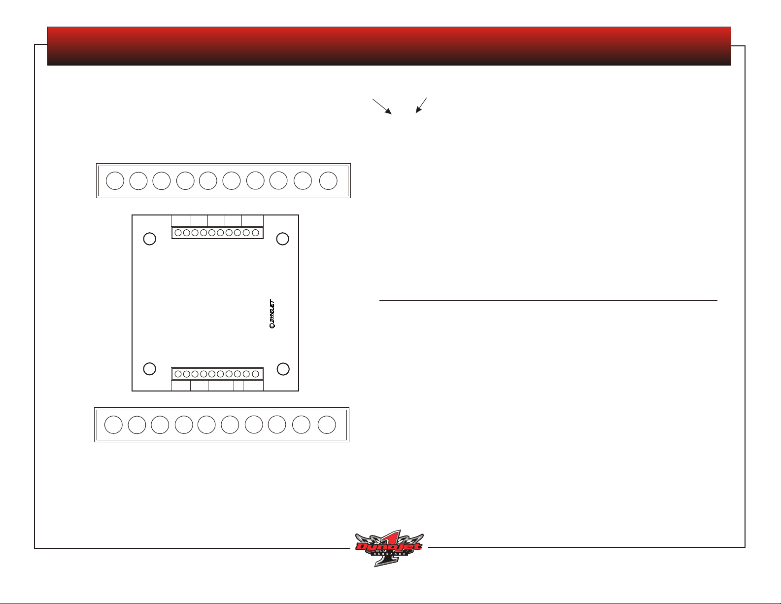
4WD MOVEMENT BOARD TEST
Use a multi-meter to read each terminal and determine the voltage that
should be present as listed on this sheet.
The red probe is always placed on the first number.
TB2: Top Row of Terminals on PCB
Reading Left to Right
10
7
8
9
5
6
3
4
1
2
TB2
IN
OUT
BRK 1
BRK 2
TB2
4WD Movement
65412001
RAIL
03/16/00
DYNOJET RESEARCH,
INC
red probe
on first
number
black
probe
10—9 brake signal to cable
brake off +12 VDC
brake on 0 VDC
8—7 brake signal to solenoid
brake off +12 VDC
brake on 0 VDC
6—5 11.57 VDC when IN switch on remote is pushed
4—3 11.57 VDC when OUT switch on remote is pushed
2—1 10.68 VDC when either IN/OUT switch is pushed on remote
1—2 brake signal from Breakout board
brake off +12 VDC
brake on 0 VDC
TB1
BRK IN
1
2
3
TB1
TB1: Bottom Row of Terminals on PCB
Reading Left to Right
98225108 • Version 1 • Page 2 of 2
For assistance, call Dynojet Technical Support at 1-800-992-3525, visit www.dynojet.com, or write to Dynojet at 2191 Mendenhall Drive, North Las Vegas, NV 89031.
3—4 12 VDC in from P/S
+12V
COM
GND
PRES
IN
OUT
SW
----
5—4 when brake is applied, reads 12 VDC
6—4 with brake applied, with the remote switch pressed to IN, reads 12 VDC
7
5
4
6
8
9 10
7—4 with brake applied, with the remote switch pressed to OUT, reads 12 VDC
8— not wired
For this test, you will check for continuity:
9—10 air pressure switch: sufficient air pressure equals continuity, insufficient air
pressure equals no continuity
© Copyright 2004 Dynojet Research, Inc. All Rights Reserved. 02/2004SD
 Loading...