

Page 1

Quick Start Guide
DynoWare RT - 224 Dynos
CABLE ROUTING
Connect the pendant cable to the DynoWare RT module.
Connect the atmospheric cable to the DynoWare RT module.
Connect the four-pin communication cable from the Air Fuel Ratio module to the
DynoWare RT module.
Connect the four-pin communication cable from the front of the Eddy Current Brake driver
module to the DynoWare RT module.
Connect a primary RPM pick up cable or a secondary pick up cable to the DynoWare RT module.
Connect the six-pin speed/brake cable to position 1 on the DynoWare RT module.
Note: For 4WD dynos, connect the speed/brake cable from the stationary dyno to
position 1 and connect the speed/brake cable from the moveable dyno to position 2.
Connect the ethernet cable from the ethernet port on the DynoWare RT module to your
Local Area Network or directly to the network port on your computer. Refer to your dyno
installation guide for more information.
Connect the three-pin temperature sensor cable to the three-pin port on the Eddy Current Brake
driver module.
Note: Make these connections for both Eddy Current Brake driver modules for 4WD dynos.
DWRT ECB AFR
B
B
B
C
C
B
DynoWare RT Main Module
(DWRT)
Eddy Current Brake
Driver Module (ECB)
98200047.01
Connect the five-pin load cell cable to the five-pin port on the Eddy Current Brake driver module.
Note: Make these connections for both Eddy Current Brake driver modules for 4WD dynos.
Set the ID switch on the Eddy Current Brake driver module to 0 for 2WD dynos.
For 4WD dynos, set the Eddy Current Brake driver module ID switch on the
stationary dyno to 0 and set the ID switch on the moveable dyno to 2.
1. Insert the Dynojet Power Core CD in your CD-ROM drive. The launch program will run automatically.
If auto-run is disabled on your computer, click Start on the Windows task bar, and click Run.
Type D:\setup.exe, where D corresponds to your CD-ROM drive.
2. Follow the on-screen instructions to install the Power Core software.
3. Double-click the Power Core program icon installed on your desktop or on your start menu. This will
run the Dynojet Application Launcher.
4. Click WinPEP 8 Dyno Control from the Application Launcher.
5. Connect to DynoWare RT Control. See page 2 for more information.
6. Turn on the DynoWare RT main module. Allow several minutes for your computer to
connect to the main module.
Dynojet Research 2191 Mendenhall Drive North Las Vegas, NV 89081
1-800-992-4993 www.dynojet.com
I.D.
Air Fuel Ratio Module
(AFR)
INSTALL YOUR SOFTWARE
Page 2
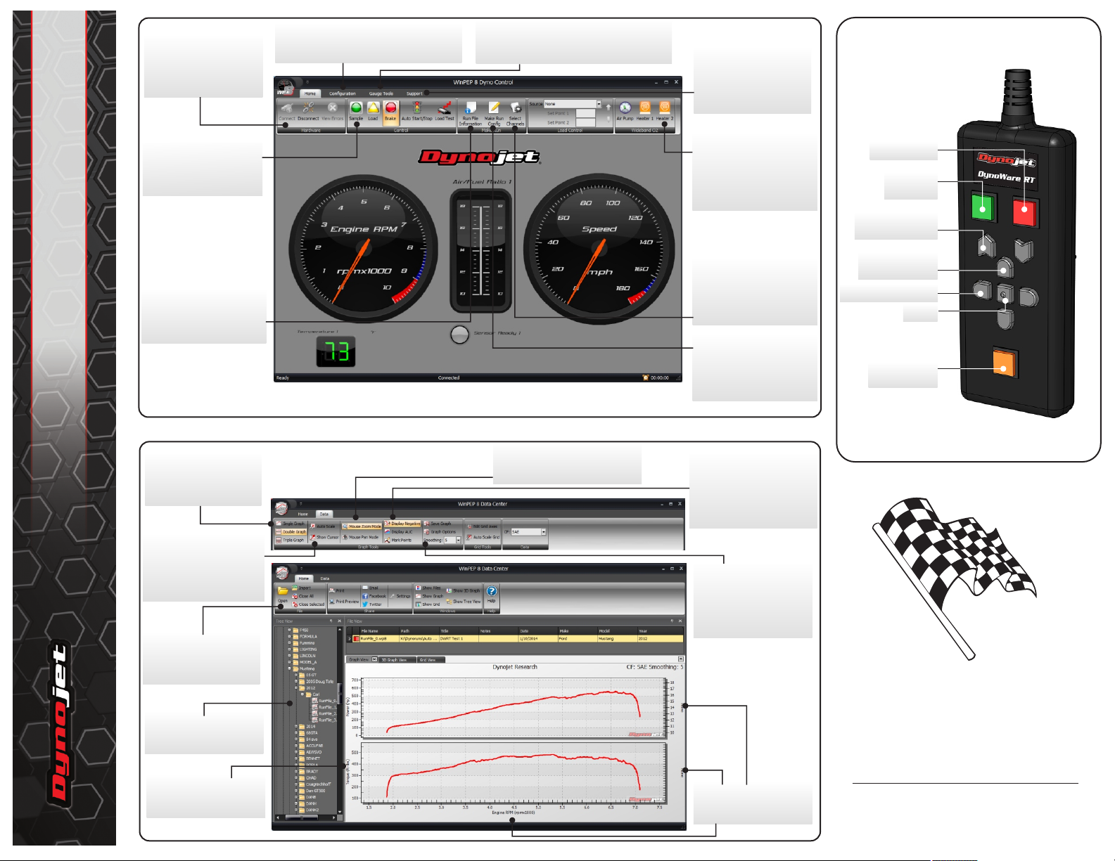
Get Connected
Check the Connect
Automatically box, choose
DynoWare RT, and Click
Connect.
Configuration Options
Calibrate the load cells, select the RPM
source, and configure your analog sensors.
Manage your Gauges
Choose a template or design your own! Add
a new gauge and configure existing gauges.
PENDANT OVERVIEW
Get Help
Update your device, get
device support, and find
answers to your questions
using the Help.
DynoWare RT - 224 Dynos
98200047.01
Ready to Sample
Click Sample or the green
button on the pendant to
start a run.
Save Run File Info
Enter vehicle data, notes,
and important run file
information.
WINPEP 8 DYNO CONTROL
Want to see more
graphs?
Switch views between
one, two, or three graphs.
View cursor and all data
When zoomed or panned,
click Auto Scale to show all
data. Click Show Cursor to
show or hide the cursor.
Manage your runs
Use the File functions to
browse for, open, import
and close your runs.
Tree View
Browse to your run files.
Double-click to view a file.
Choose your channels
Click any axis to view a list
of channel options.
WINPEP 8 DATA CENTER
Home and Data Ribbons
Zoom and pan
When highlighted, click and drag
on the graph to zoom or pan.
Have a Wideband O2?
Activate the AFR Pump and
O2 sensor heaters. When
the sensor is in an exhaust
bung, the pump can be left
off.
Log Data Channels
Choose which data
channels will be logged.
Any channel assigned to a
gauge will be logged.
Dyno Run Options
Set your dyno run options in
Make Run Config.
Show the information
you need
Click Display AUC to view
the area under the curve.
Click Mark Points to view the
data points on the graph.
More Graph Options
Save your graph as an
image file, change the axis
scaling and add labels to
your graph, and control
the smoothing level.
Choose your channels
Click any axis to view a list
of channel options.
Brake on/off
Sample
start/stop
Load control set
point up/down
Brings dyno
control to front
Left/Right in dialog
Okay
Load Control
on/off
The Next Step
Congratulations!
You are now ready to use your new
Dynoware RT integrated platform.
Access more detailed Dynoware RT
installation and user instructions in the
Dynojet Power Core Software Help.
For more information on Dynoware RT,
visit us online at www.dynojet.com
or call 800-992-4993.
 Loading...