

Page 1

CLUTCH KIT
INSTALLATION GUIDE
2020 Canam X3 RR models
PARTS LIST
6 CLUTCH ARMS
1 PRIMARY SPRING GOLD
1 SECONDARY SPRING LIGHT GREEN
PLEASE READ ALL DIRECTIONS BEFORE STARTING INSTALLATION
THIS KIT REQUIRES SPECIAL TOOLS FOR INSTALLATION.
FOR BEST RESULTS, DYNOJET RECOMMENDS
INSTALLATION BY A QUALIFIED TECHNICIAN.
2191 MENDENHALL DRIVE, NORTH LAS VEGAS, NV 89081
800-992-4993 WWW.DYNOJET.COM
25-DCK3
24 MAGNETS (3/8”)
12 WASHERS
Page 2
CLUTCH KIT ADJUSTMENT
SETTINGS
INTENDED USE ELEVATION MAGNETS TOTAL WEIGHT PRIMARY SPRING SECONDARY SPRING HELIX POS
Trail Std Tire
Paddle Tire / Heavy load
0-4000 ft 2 52 gr GOLD LIGHT GREEN 1
0-4000 ft 1 50 gr GOLD LIGHT GREEN 1
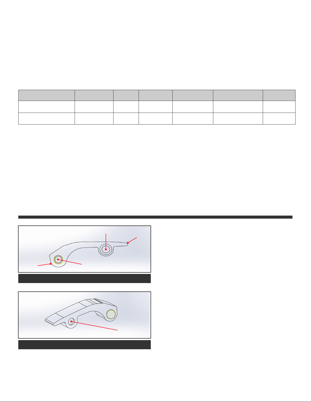
CLUTCH ARM ADJUSTMENT
MAGNET POS
TOE
HEEL
LOAD MAGNETS STARTING AT HEEL - POS #1
PIVOT
LOAD MAGNETS PER THE TABLE ABOVE. MAKE SURE EACH
CLUTCH ARM IS LOADED WITH THE SAME AMOUNT OF
WEIGHT.
1 MAGNET CHANGE ON EACH ARM WILL ALTER
•
RPM APPROXIMATELY 150RPM
WHERE THE SPRING IS INDICATED ON THE
•
HELIX ALSO AFFECTS TARGET RPM
OUR SETTINGS ARE A GENERAL BASELINE. MANY THINGS
CAN EFFECT CLUTCH SETUP:
USE A SMALL
ALLEN KEY OR
SIMILAR TO PUSH
THE MAGNETS
OUT FROM THIS
SIDE
TO REMOVE MAGNETS
25-DCK3 CLUTCH KIT 2020 CANAM X3 RR
TIRE BRAND & SIZE
•
STATE OF CLUTCH WEAR
•
DRIVEBELT CONDITION
•
ENGINE POWER OUTPUT
•
ENVIRONMENT CONDITIONS
•
Page 3

INSTALLATION INSTRUCTIONS
IT IS RECOMMENED TO HAVE AN AUTHORIZED CANAM
TECHNICIAN INSTALL THE CLUTCH KIT AS SPECIAL TOOLS
ARE NEEDED TO COMPLETE THE INSTALLATION.
Remove all the 8mm head bolts for the plastic, clutch
housing. Remove clutch housing. Mark the direction of the
drivebelt. Remove the drivebelt. Although there are arrows
on the sheaves it is a good idea to make a mark that you
can easily see to ensure proper alignment when reinstalling. Using the Canam clutch puller part #529 035 746 remove the primary clutch. It is recommended to grease the
threads of the clutch puller before usage.
To disasemble the primary clutch use special tool 529 036
350.
Remove the 6 bolts
for the spring cover to access the
primary spring.
Replace the primary spr ing with the supplied Dynojet
GOLD spring. Reverse order of disassembly. Make sure
to clean the taper of the assembly and the face of the
sheaves properly. When installing the primary assembly
back on the crankshaft make sure that your original marks
are aligned before tightening. Replace the drive pulley
screw and torque to 89lb/ft.
Remove the secondary
clutch assembly from the
vehicle. To disasseble the
secondary clutch use special tool part #529 036 012.
Take notice of the arrow
marks on each sheave. It is
best to make marks on the
edge of each sheave with a
marker for ease of reassembly.
Once the sheaves have been separated you can remove the
special tool. Slide the governor cup out of the guides. If the
slider shoes fall out make sure you inspect the slider and
O’ring.
Remove the stock clutch arms using a T25 torx and 8mm
wrench. Replace with the Dynojet arms using the required number of magnets per chart on page 2. Make sure
to reinstall the stock thrust washers on each side of the
arms. There are replacement washers included in the kit if
needed.
Place special tool part # 529 036 012 in a secure vice. Slide
primary assembly over the tool and tighten down the tool
over the spring cover. Remove the 6 bolts holding the sping
cover in place. Remove the special tool.
#1
#6
#5
#2
#3
#4
While the secondary is compressed remove the 3 torx
cam retaining screws.
With the secondary clutch
disassembled inspect the
cam.
The #1 location in this pic
is the location where the
STOCK alignment arrow is.
INSTALLATION GUIDE
Page 4

Slide the secondary sheave onto the special tool. Put the stock plastic cup and Dynojet Light Green spring into the sheave
making sure the tab on the spring is inserted into the hole in the sheave correctly. Install the cam over the spring engaging
the hole location per the chart on page 2. Rotate the sheave per the pictures below so the roller engages the next finger.
CAM POSITION #1
Rotate cam 130°
Roller
Roller
STOCK CAM POSITION CAM POSITION #3
Rotate cam 90°
Align the marks on each sheave. Fully compress the sheaves and
reinstall the 3 torx screws to 45 lb/ft. Clean the sheaves thoroughly
and the transmission shaft. Reinstall the secondary clutch assembly onto the transmission shaft. Replace the bolt and torque to 52
lb/ft.
Rotate cam 50°
Roller
FINGER AND ROLLER ENGAGMENT
TUNING NOTES
For best performance your RPM when checked at 55 mph should be 7850-8000rpm. This should be checked on a surface
that offers good traction and tested with normal load in the vehicle. Adjustments to overall weight of each clutch arm and/
or secondary springs may be necessary to achieve this RPM target.
If you were to test on the street and then ride in the sand or mud it is not uncommon to see a loss of 300-400rpm if using
paddle tires.
Our settings are based on using a PowerVision tune in the ECM for optimal performance.
TOOLS NEEDED FOR INSTALLATION
DYNOJET CLUTCH SERVICE KIT 16300002
•
8MM SOCKET
•
T27 TORX
•
T30 TORX
•
22MM SOCKET
•
17MM SOCKET
•
25-DCK3 CLUTCH KIT 2020 CANAM X3 RR
Page 5

PUSH THE LIMIT.
WWW.DYNOJET.COM
© 2018 DYNOJET RESEARCH ALL RIGHTS RESERVED
INSTALLATION GUIDE
 Loading...