

Page 1
Page 2

©2008 Dynojet Research, Inc. All Rights Reserved.
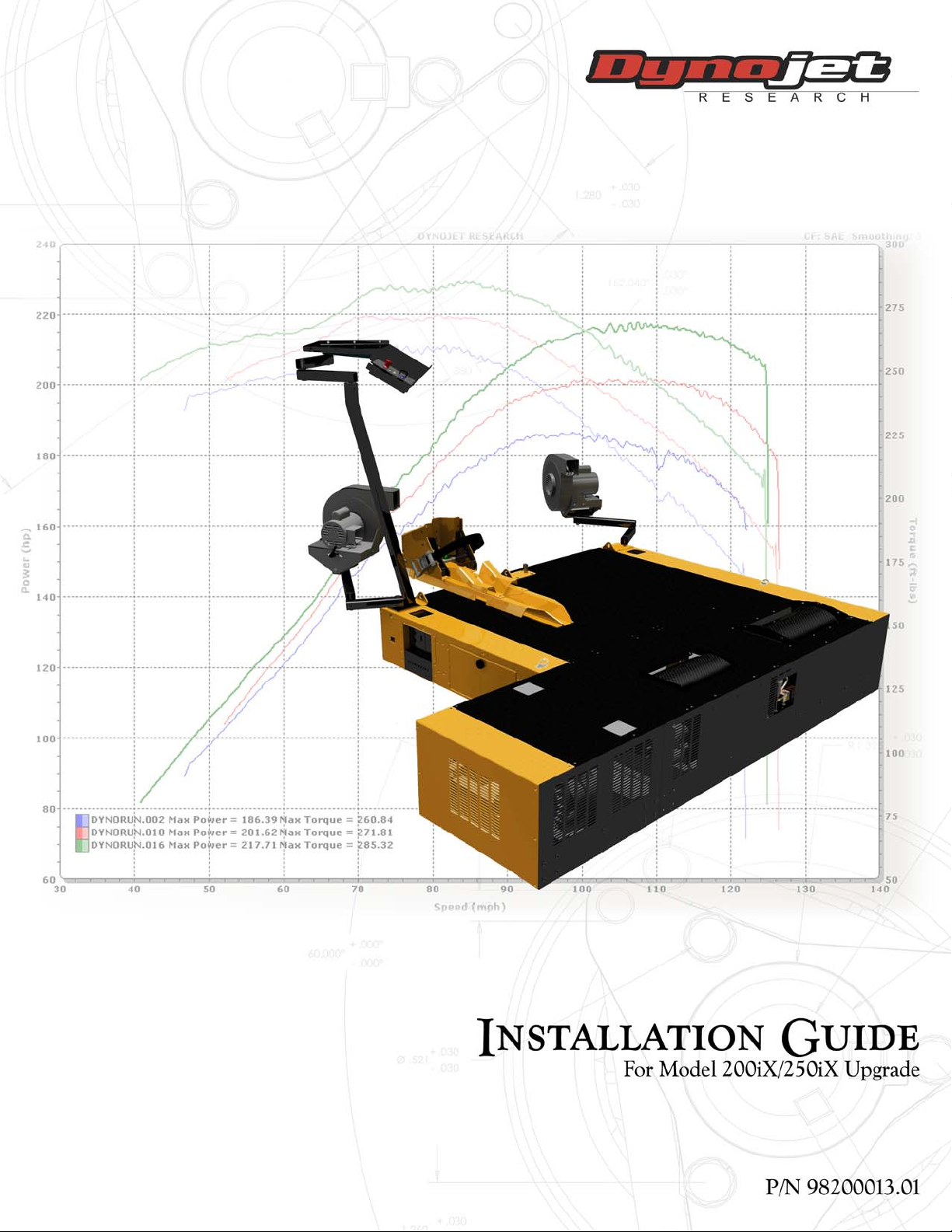
Model 200iX/250iX Upgrade Installation Guide
This manual is copyrighted by Dynojet Research, Inc., hereafter referred to as Dynojet,
and all rights are reserved. This manual, as well as the software described in it, is
furnished under license and may only be used or copied in accordance with the terms of
such license. This manual is furnished for informational use only, is subject to change
without notice, and should not be construed as a commitment by Dynojet. Dynojet
assumes no responsibility or liability for any error or inaccuracies that may appear in this
manual. Except as permitted by such license, no part of this manual may be reproduced,
stored in a retrieval system, or transmitted, in any form or by any means, electronic,
mechanical, recording, or otherwise, without the prior written permission of Dynojet.
The Dynojet logo is a trademark of Dynojet Research, Inc.
Any trademarks, trade names, service marks, or service names owned or registered by any
other company and used in this guide are the property of their respective companies.
Dynojet Research, Inc., 2191 Mendenhall Drive, North Las Vegas, Nevada 89081, USA.
Printed in USA.
Part Number: 98200013 Version 01 (03/2008)
Page 3

T
ABLE OF
C
ONTENTS
Warnings . . . . . . . . . . . . . . . . . . . . . . . . . . . . . . . . . . . . . . . . . . . . . . . . iii
Chapter 1 Model 200iX/250iX Upgrade
Introduction . . . . . . . . . . . . . . . . . . . . . . . . . . . . . . . . . . . . . . . . . . . . . . . . . .1-2
Conventions Used In This Manual . . . . . . . . . . . . . . . . . . . . . . . . . . . . . . .1-2
Technical Support . . . . . . . . . . . . . . . . . . . . . . . . . . . . . . . . . . . . . . . . . . .1-2
Model 200iX/250iX Upgrade Specifications . . . . . . . . . . . . . . . . . . . . . . . .1-3
Chassis Specifications . . . . . . . . . . . . . . . . . . . . . . . . . . . . . . . . . . . . . . . . .1-3
Dyno Preparation . . . . . . . . . . . . . . . . . . . . . . . . . . . . . . . . . . . . . . . . . . . . .1-6
Disconnecting the Power . . . . . . . . . . . . . . . . . . . . . . . . . . . . . . . . . . . . . .1-6
Removing the High Pressure Blower Assemblies . . . . . . . . . . . . . . . . . . . . .1-7
Removing the Monitor Stand . . . . . . . . . . . . . . . . . . . . . . . . . . . . . . . . . . .1-8
Removing the Dyno Panels . . . . . . . . . . . . . . . . . . . . . . . . . . . . . . . . . . . .1-9
Drum Installation . . . . . . . . . . . . . . . . . . . . . . . . . . . . . . . . . . . . . . . . . . . . .1-10
Removing the Items from Crate . . . . . . . . . . . . . . . . . . . . . . . . . . . . . . . .1-10
Installing the iX Drum Module . . . . . . . . . . . . . . . . . . . . . . . . . . . . . . . . .1-12
Bulkheads and Covers . . . . . . . . . . . . . . . . . . . . . . . . . . . . . . . . . . . . . . . . .1-15
Installing the Bulkheads . . . . . . . . . . . . . . . . . . . . . . . . . . . . . . . . . . . . . .1-15
Installing the Panels and Covers . . . . . . . . . . . . . . . . . . . . . . . . . . . . . . . .1-17
Trike Carriage Adapter Installation . . . . . . . . . . . . . . . . . . . . . . . . . . . . . .1-20
Removing the Carriage Screw and Carriage . . . . . . . . . . . . . . . . . . . . . . . 1-21
Removing the Carriage Clamps, Shims, and Nut Block . . . . . . . . . . . . . . .1-22
Installing the Trike Carriage Adapter Assembly . . . . . . . . . . . . . . . . . . . . .1-23
Installing the Carriage Assembly . . . . . . . . . . . . . . . . . . . . . . . . . . . . . . . .1-24
Tie-Down Installation . . . . . . . . . . . . . . . . . . . . . . . . . . . . . . . . . . . . . . . . .1-25
Monitor Stand and Blowers Installation . . . . . . . . . . . . . . . . . . . . . . . . . .1-26
Ground Hook Installation . . . . . . . . . . . . . . . . . . . . . . . . . . . . . . . . . . . . . .1-28
Model 200iX/250iX Upgrade Installation Guide
i
Page 4

TABLE OF CONTENTS
Chapter 2 Basic Dyno Operation
Loading the Vehicle . . . . . . . . . . . . . . . . . . . . . . . . . . . . . . . . . . . . . . . . . . .2-2
Connecting the RPM Pickup . . . . . . . . . . . . . . . . . . . . . . . . . . . . . . . . . . . .2-4
RPM Pickup Descriptions . . . . . . . . . . . . . . . . . . . . . . . . . . . . . . . . . . . . . .2-4
Connecting the Secondary Inductive Pickup . . . . . . . . . . . . . . . . . . . . . . .2-5
Connecting The Primary Inductive Pickup . . . . . . . . . . . . . . . . . . . . . . . . . 2-6
Pre-Run Inspection . . . . . . . . . . . . . . . . . . . . . . . . . . . . . . . . . . . . . . . . . . . .2-7
Before Starting the Engine . . . . . . . . . . . . . . . . . . . . . . . . . . . . . . . . . . . . .2-8
Engine Warm Up . . . . . . . . . . . . . . . . . . . . . . . . . . . . . . . . . . . . . . . . . . . .2-8
After Engine Warm Up . . . . . . . . . . . . . . . . . . . . . . . . . . . . . . . . . . . . . . . .2-8
Making a Test Run . . . . . . . . . . . . . . . . . . . . . . . . . . . . . . . . . . . . . . . . . . . .2-9
Preventative Maintenance . . . . . . . . . . . . . . . . . . . . . . . . . . . . . . . . . . . . .2-10
Appendix A Red Head Anchor Installation
Installation . . . . . . . . . . . . . . . . . . . . . . . . . . . . . . . . . . . . . . . . . . . . . . . . . . .A-2
Appendix B Ramp Kit Installation
Ramp Installation . . . . . . . . . . . . . . . . . . . . . . . . . . . . . . . . . . . . . . . . . . . . . .B-2
Index . . . . . . . . . . . . . . . . . . . . . . . . . . . . . . . . . . . . . . . . . . . . . . . . . Index-i
ii
Model 200iX/250iX Upgrade Installation Guide
Page 5

W
ARNINGS
Disclaimers
Dynojet Research, Inc. (Dynojet) makes no representation or warranties with respect to the contents
hereof and specifically disclaims any implied warranties of merchantability for any particular purpose.
Dynojet reserves the right to revise this publication and to make changes from time to time in the
content hereof without obligation of Dynojet to notify any person of such revision or changes.
Dynojet is not responsible for false operation due to unexpected dynamometer operation such as may
be caused by static, software bugs, hardware failure, etc.
Dynojet is not responsible for damage resulting from improper installation of the dynamometer or
from improper service rendered to the dynamometer. Dynojet is not responsible for damage incurred
due to alteration of the dynamometer or components, use of unapproved parts, or abuse to the
dynamometer.
Do not connect or disconnect cables or components on the dynamometer with the power on.
Always wear protective clothing, ear protection, and eye protection (goggles, safety glasses) when
using and servicing the dynamometer.
Equipment Power Requirements
The dynamometer has specific power requirements. Connecting the dynamometer to the incorrect
voltage will void the dynamometer warranty. Installation may require a licensed electrician.
Potentially Lethal Voltages
Components attached to and within the dynamometer operate with potentially lethal voltages. To
provide the greatest assurance of safety, the AC power cord(s) must be disconnected from the power
source before servicing electrical components or wiring. Disconnect all power cords before servicing
electrical components for the greatest assurance of safety.
Model 200iX/250iX Upgrade Installation Guide
iii
Page 6

WARN IN GS
Electrostatic Discharge Precautions
Electrostatic Discharge
Electrostatic Discharge (ESD), or static shock, can damage electronic components within the
dynamometer. The damage may occur at the time of an ESD occurrence, or the shock may degrade
the component, resulting in a premature component failure later. To avoid ESD damage, always
practice good ESD control precautions when servicing the dynamometer. Dynojet designs its
dyna mo me te rs to be v er y t olerant of st atic sh oc ks by the users, but the electronics are vulnerable when
the electronics are exposed. ESD occurs as a result of a difference of potential between two objects
when the two objects touch. Damage occurs as a result of the energy released when the discharge
(touch) occurs. The difference of potential can accumulate by as simple an action as a user moving
across carpet or a seat. If that person’s energy is discharged directly to the electronics, the electronics
can be damaged.
Precautions
To protect against ESD damage, you must eliminate the difference of potential before the electronics
are handled. Touch the chassis of the dynamometer before touching any of the electronics. By touching
the chassis, you discharge any static shocks to the chassis instead of to the electronics.
If you are holding a circuit board or dynamometer component in your hand when you approach the
machine, touch the chassis of the dynamometer with your hand before installing the circuit board or
component.
When handling a circuit board or component to someone, touch that person with your hand first,
then hand them the component.
Always carry circuit boards in anti-static bags when the boards are exposed (removed from the
dynamometer).
Battery Fire and Explosion Hazards
There is a danger of explosion if the battery is incorrectly replaced. Replace only with the same or
equivalent type recommended by the manufacturer. Discard used batteries according to the
manufacturer’s instructions.
Automotive Batteries
In operation, batteries generate and release flammable hydrogen gas. They must always be assumed
to contain this gas which, if ignited by burning cigarette, naked flame or spark, may cause battery
explosion with dispersion of casing fragments and corrosive liquid electrolyte. Carefully follow
manufacturer's instructions for installation and service. Keep away all sources of gas ignition and do
not allow metallic articles to simultaneously contact the negative and positive terminals of a battery.
Do not allow the positive and negative terminals to short-circuit. The dynamometer chassis is tied to
the negative side of the battery. Do not short between the positive battery terminal or the starter
connections to the chassis. In addition, make sure metal tools such as screw drivers, wrenches, and
torque wrenches do not come in contact with the negative and positive terminals of the battery. Short
circuiting the terminals of the battery can cause burn injuries, damage to the dynamometer, or trigger
explosions.
Charging
Batteries being charged will generate and release flammable hydrogen gas. Charging space should be
ventilated. Keep battery vent caps in position. Prohibit smoking and avoid creation of flames and sparks
nearby.
Wear protective clothing, eye and face protection, when charging or handling batteries.
iv
Model 200iX/250iX Upgrade Installation Guide
Page 7

WAR NIN GS
Other Potential Hazards
The AC power outlet shall be installed near the equipment and it shall be easily accessible to allow for
disconnect before service.
The dynamometer should be located in a well ventilated area. There is a carbon monoxide hazard with
all internal combustion engines. Engine exhaust contains poisonous carbon monoxide gas. Breathing
it could cause death.
Any dyno room design must incorporate sufficient exhaust extraction.
Always wear proper ear and eye protection when operating the dynamometer.
Never operate the dynamometer with the covers removed.
Never stand behind the dynamometer when in operation.
Never operate the dynamometer when there is excessive vibration or noise. Resolve these problems
before proceeding.
Never fuel the vehicle on the dynamometer unless appropriate safety measures are taken.
Verify brake operation before beginning any dynamometer testing.
Verify the vehicle is properly secured to the dynamometer.
Never operate the blowers without the guards installed.
Exercise care with any dynamometer testing; portions of the dynamometer and vehicle may become
hot.
As with any equipment using electricity and having moving parts, there are potential hazards. To use
this dynamometer safely, the operator should become familiar with the instructions for operation of
the dynamometer and always exercise care when using it.
Do not repair or replace any part of the dynamometer or attempt any servicing unless specifically
recommended in published user-repair instructions that you understand and have the skills to carry
out.
Vers ion 1 Model 200iX/250iX Upgrade Installation Guide
v
Page 8

Page 9

M
ODEL
C HAPTER
200IX/250IX U
1
PGRADE
Thank you for purchasing the 200iX/250iX upgrade for Dynojet’s Model 200i/250i
Motorcycle Dynamometer. This upgrade will allow you to run a kart, ATV, or trike on
your motorcycle dynamometer. Dynojet’s software and dynamometers will give you
the power to get the maximum performance out of vehicles you evaluate. Whether
you are new to the benefits of a chassis dynamometer or an experienced performance
leader, the repeatability and diagnostic tools of WinPEP 7 software and a Dynojet
dynamometer will give you the professional results you are looking for.
This document provides instructions for installing the 200iX/250iX upgrade to
Dynojet’s Model 200i/250i Motorcycle Dynamometer (dyno). This document will walk
you through the installation and basic dyno operation along with installing the
optional ramp. To ensure safety and accuracy in the procedures, perform the
procedures as they are described.
Document Part Number: 98200013
Vers i on 1
Last Updated: 03-07-08
This section is divided into the following categories:
•Introduction, page 1-2
• Model 200iX/250iX Upgrade Specifications, page 1-3
•Dyno Preparation, page 1-6
• Drum Installation, page 1-10
• Bulkheads and Covers, page 1-15
• Trike Carriage Adapter Installation, page 1-20
• Tie-Down Installation, page 1-25
• Monitor Stand and Blower Installation, page 1-26
• Ground Hook Installation, page 1-28
Model 200iX/250iX Upgrade Installation Guide
1-1
Page 10
CHAPTER 1
Introduction
INTRODUCTION
. . . . . . . . . . . . . . . . . . . . . . . . . . . . . . . . . . .
Before installing your 200iX/250iX upgrade, please take a moment to read this guide
for installation instructions, dyno features, and other important information.
CONVENTIONS USED IN THIS MANUAL
The conventions used in this manual are designed to protect both the user and the
equipment.
example of convention description
The Caution icon indicates a potential hazard to the
dynamometer equipment. Follow all procedures
exactly as they are described and use care when
performing all procedures.
The Warning icon indicates potential harm to the
person performing a procedure and/or the
dynamometer equipment.
TECHNICAL SUPPORT
For assistance, please contact Dynojet Technical Support at 1-800-992-3525, or write
to Dynojet at 2191 Mendenhall Drive, North Las Vegas, NV 89081.
Visit us on the World Wide Web at www.dynojet.com where Dynojet provides state of
the art technical support, on-line shopping, and press releases about our latest
product lines.
1-2
Model 200iX/250iX Upgrade Installation Guide
Page 11

MODEL 200IX/250IX UPGRADE
Model 200iX/250iX Upgrade Specifications
MODEL 200IX/250IX UPGRADE SPECIFICATIONS
. . . . . . . . . . . . . . . . . . . . . . . . . . . . . . . . . . .
The following specifications and requirements will help you set up your dyno area for
the 200iX/250iX upgrade.
Refer to the model 200i/250i installation guide for specifications and requirements for
the bike dyno.
CHASSIS SPECIFICATIONS
description specifications
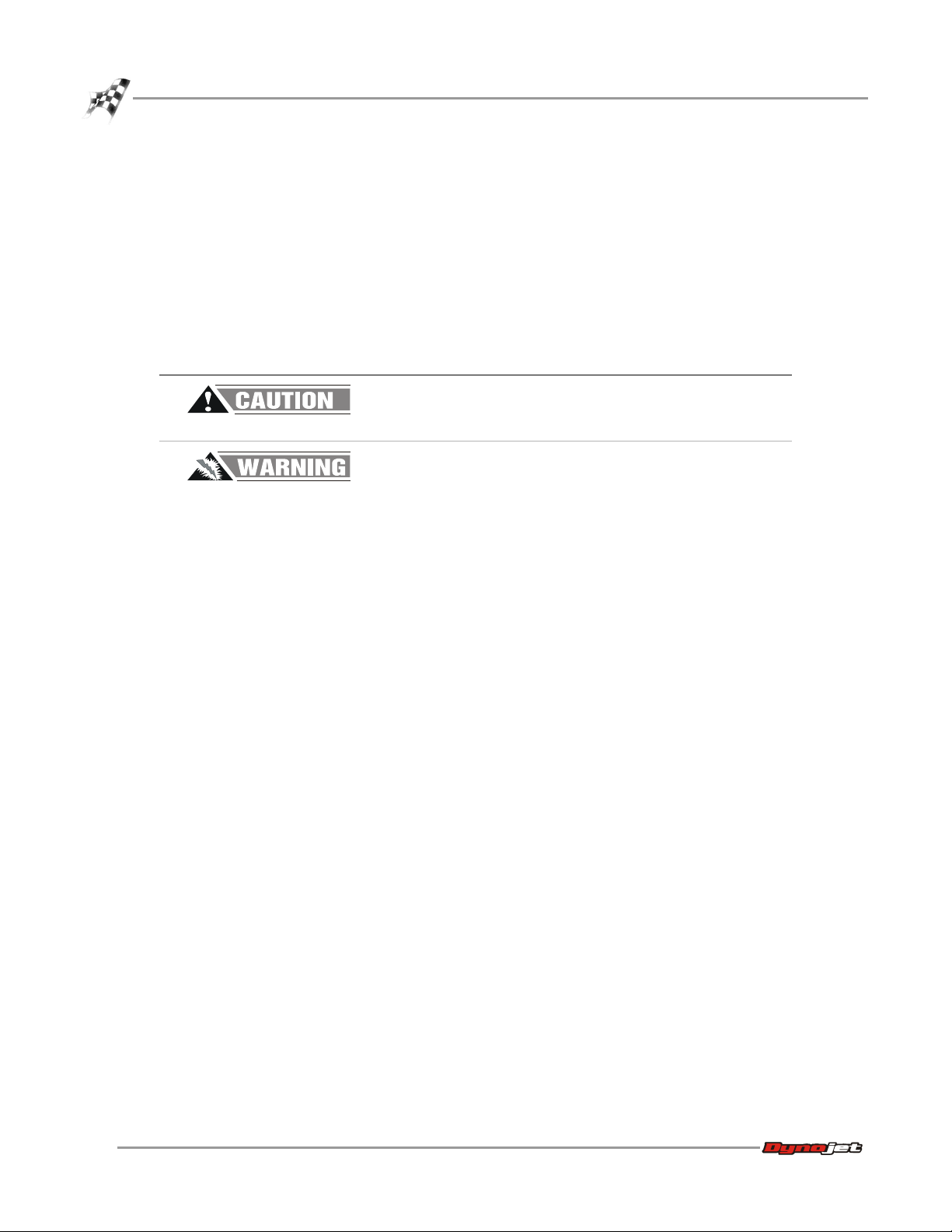
Length
dyno with standard carriage allow 271.78 cm (107.00 in.)
dyno with extended carriage allow 322.58 cm (127.00 in.)
dyno with ramp 370.84 cm (146.00 in.)
Height
to top of dyno cover 45.97 cm (18.00 in.)
Width
model 200i/200iX upgrade 200.69 cm (79.00 in.)
model 250i/250iX upgrade 274.32 cm (108.00 in.)
Weig ht
200iX/250iX drum module/crated 136 kg (300 pounds)/272 kg (600 pounds)
Drum
diameter, 200iX/250iX upgrade 45.72 cm (18.00 inches)
width, 200iX/250iX upgrade 55.88 cm (22.00 inches)
Frame structural steel channel and angle
Maximum Speed 322 KPH (200 MPH)
Maximum Motorcycle Length (front of
front wheel to center of rear wheel)
standard carriage 213 cm (84.00 inches)
extended carriage 256.54 cm (101.00 inches)
Remote Switches remote software control
Vers ion 1 Model 200iX/250iX Upgrade Installation Guide
1-3
Page 12
CHAPTER 1
Model 200iX/250iX Upgrade Specifications
Figure 1-1: Model 250iX Dyno Dimensions
1-4
Model 200iX/250iX Upgrade Installation Guide
Page 13
MODEL 200IX/250IX UPGRADE
Model 200iX/250iX Upgrade Specifications
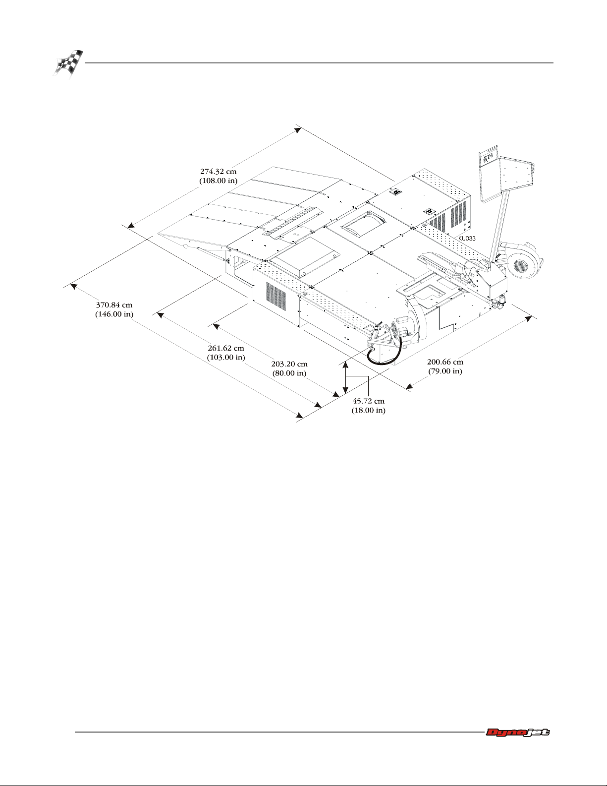
Folding Ramp Option
(iX Upgrade)
iX Drum Module
Folding Ramp Option
(Dyno)
Eddy Current
Brake
iX Upgrade
Monitor Support
Model 250i Dyno
Trike Carriage
Adapter
and Tray
High Pressure
Blower
Wheel Clamp
Option
Power Carriage
Option
Figure 1-2: Model 250iX Dyno with Accessories
Vers ion 1 Model 200iX/250iX Upgrade Installation Guide
1-5
Page 14
CHAPTER 1
Dyno Preparation
DYNO PREPARATION
. . . . . . . . . . . . . . . . . . . . . . . . . . . . . . . . . . .
Use the following instructions to prepare the dyno for installing the upgrade kit.
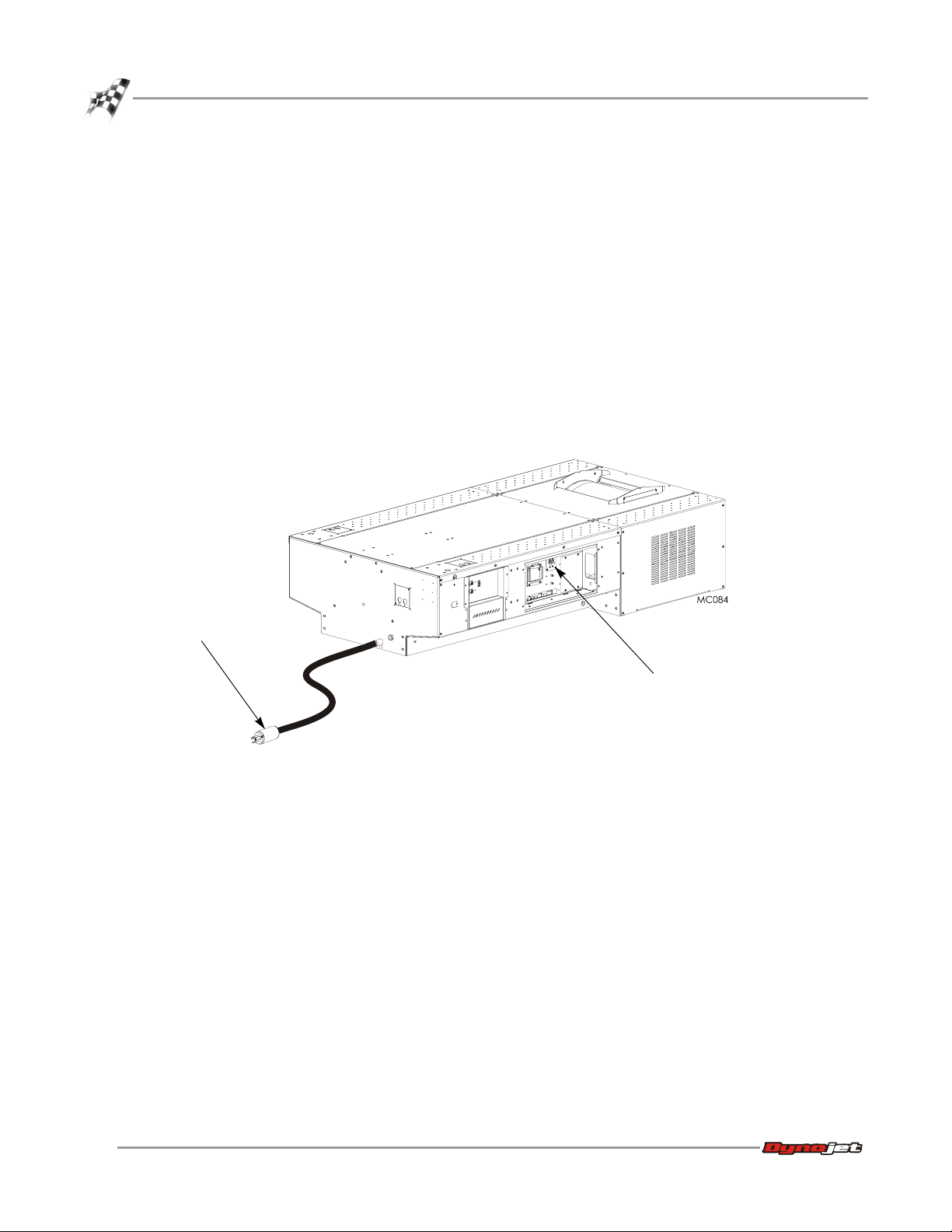
DISCONNECTING THE POWER
Use the following steps to connect and disconnect power to the dyno.
Always turn the power off when connecting and disconnecting cables.
1 Use the main breaker to turn power on and off to the dyno.
The main breaker is located inside the CPI door. When the handle is in the down
position all power into the dyno is turned off.
2 Disconnect the power plug to ensure all power has been removed from the dyno
before performing certain installation procedures.
power plug
main breaker
Figure 1-3: Main Dyno Power
1-6
Model 200iX/250iX Upgrade Installation Guide
Page 15
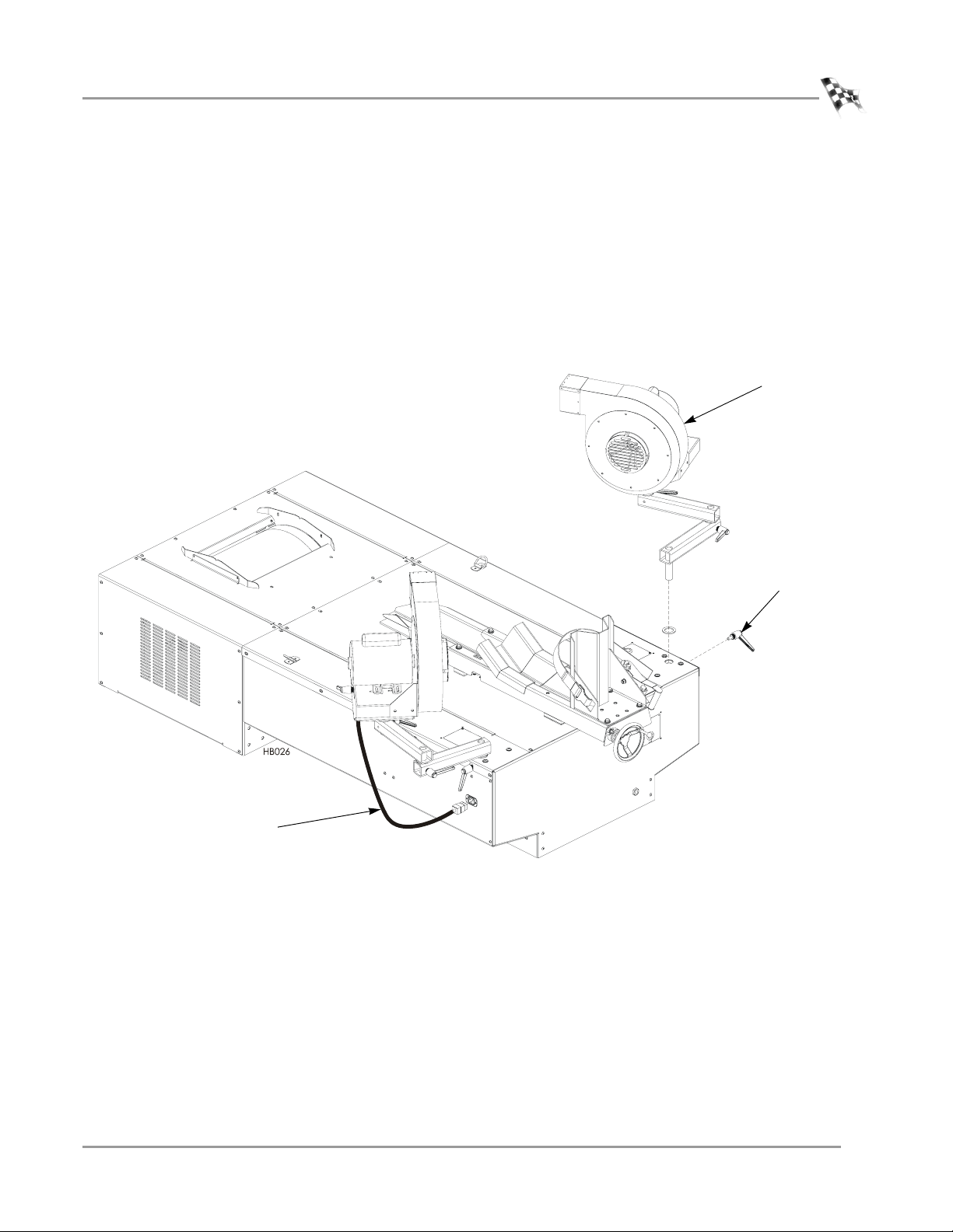
REMOVING THE HIGH PRESSURE BLOWER ASSEMBLIES
1 Unplug each high pressure blower power cord from the dyno chassis.
2 Remove the clamp lever securing the blower arm assembly to the dyno and
discard. Do this for both blower assemblies.
3 Lift the blower and arm assembly from the dyno and set aside. Do this for both
blower assemblies.
Note: Both blower assemblies must be removed in order to replace the lower
blower arm. A new lower blower arm is needed to work with the new upgrade tiedowns.
MODEL 200IX/250IX UPGRADE
Dyno Preparation
blower and arm
assembly
power cord
from blower
clamp lever
Figure 1-4: Removing the Blower Assemblies
Vers ion 1 Model 200iX/250iX Upgrade Installation Guide
1-7
Page 16
CHAPTER 1
Dyno Preparation
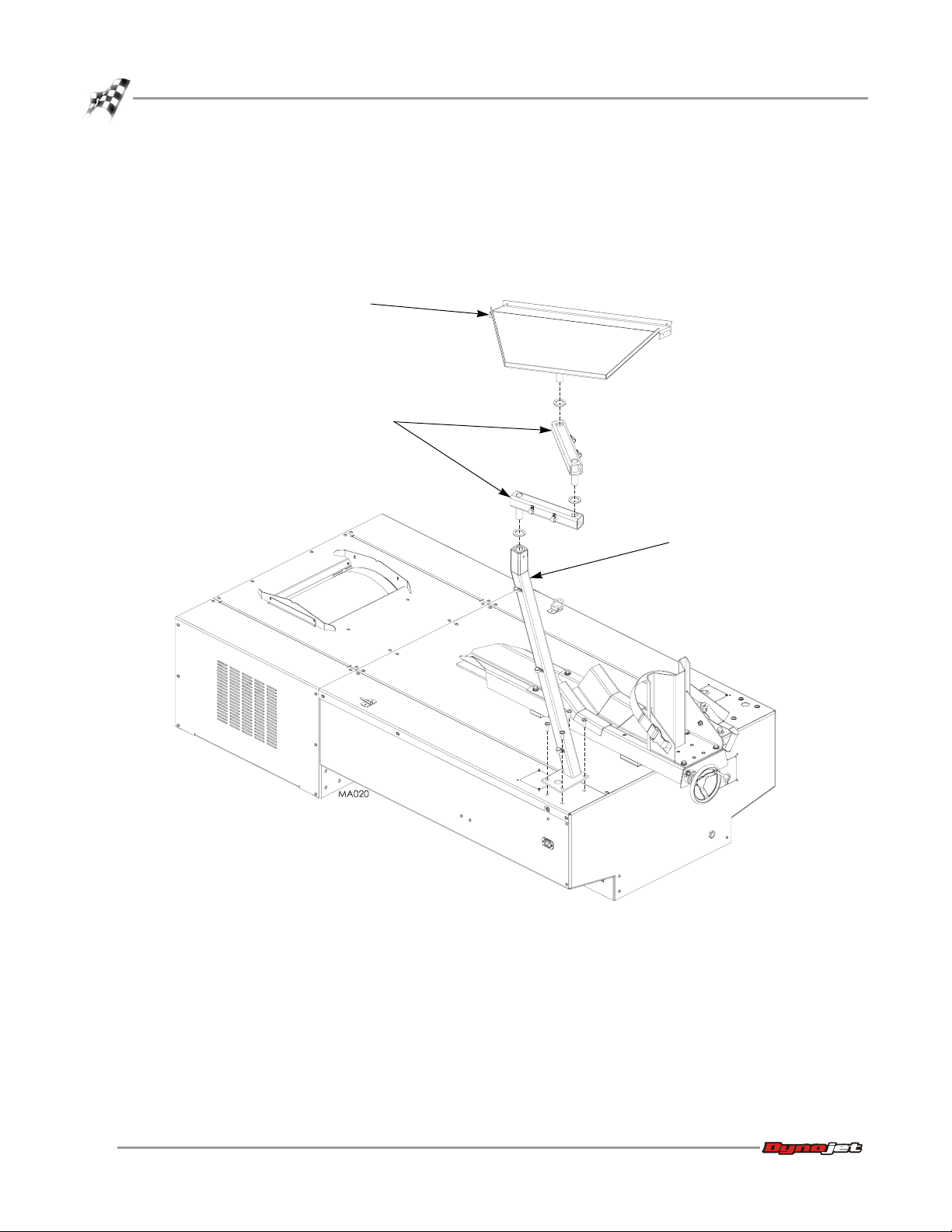
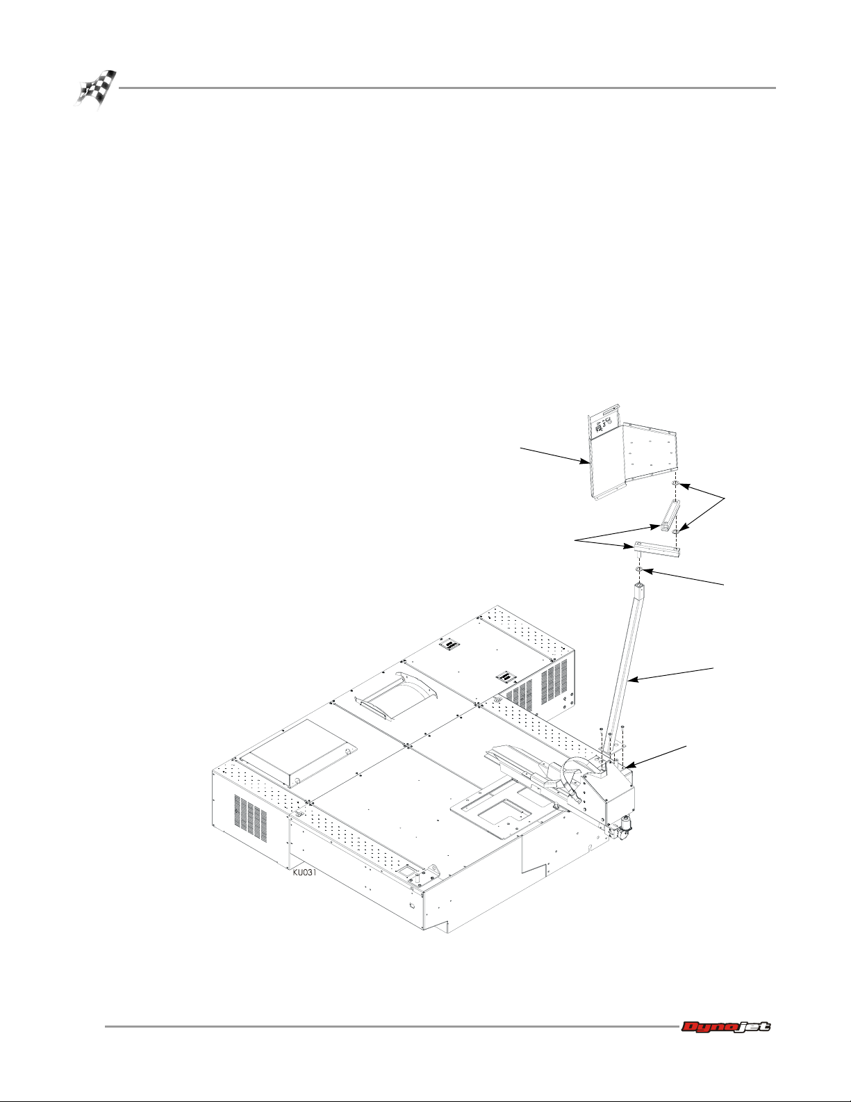
REMOVING THE MONITOR STAND
1 Disconnect all cables from the monitor stand.
2 Remove the monitor arms and tray.
3 Remove the four screws securing the monitor support and set aside.
4 Remove the monitor support and set aside.
monitor tray
monitor arms
monitor support
Figure 1-5: Removing the Monitor Stand
1-8
Model 200iX/250iX Upgrade Installation Guide
Page 17

REMOVING THE DYNO PANELS
1 Push the wires, from the monitor stand, back through the cable pass through.
Note: Perform this step only if the monitor stand was installed on the right side of
the dyno.
2 Remove the five screws securing the top panel to the dyno and set aside. Remove
the top panel and set aside.
3 Disconnect the fan power cable from the power socket on the inside of the side
panel.
4 Remove the eight screws securing the drum side panel to the dyno and set aside.
Remove the panel and set aside.
5 Remove the twelve screws securing the side panel to the dyno and set aside.
Remove the side panel and set aside.
MODEL 200IX/250IX UPGRADE
Dyno Preparation
drum side
panel
top panel
side panel
Figure 1-6: Removing the Dyno Panels
Vers ion 1 Model 200iX/250iX Upgrade Installation Guide
cable pass
through
fan power
socket
1-9
Page 18
CHAPTER 1
Drum Installation
DRUM INSTALLATION
. . . . . . . . . . . . . . . . . . . . . . . . . . . . . . . . . . .
When you receive your iX upgrade kit, examine the exterior of the shipping container
for any visible damage. If damage is detected at this stage, contact the shipper or
Dynojet before proceeding with unpacking.
Use the following steps to unload drum and items. You will need to provide
equipment capable of lifting a minimum of 272 kg (600 lb.) to move the crated drum
into position in your dyno room.
REMOVING THE ITEMS FROM CRATE
1 Move the crate to a clear area near your dyno room.
2 Using a pry bar, or a large flat screwdriver, and a hammer, carefully remove the
top and sides of the crate.
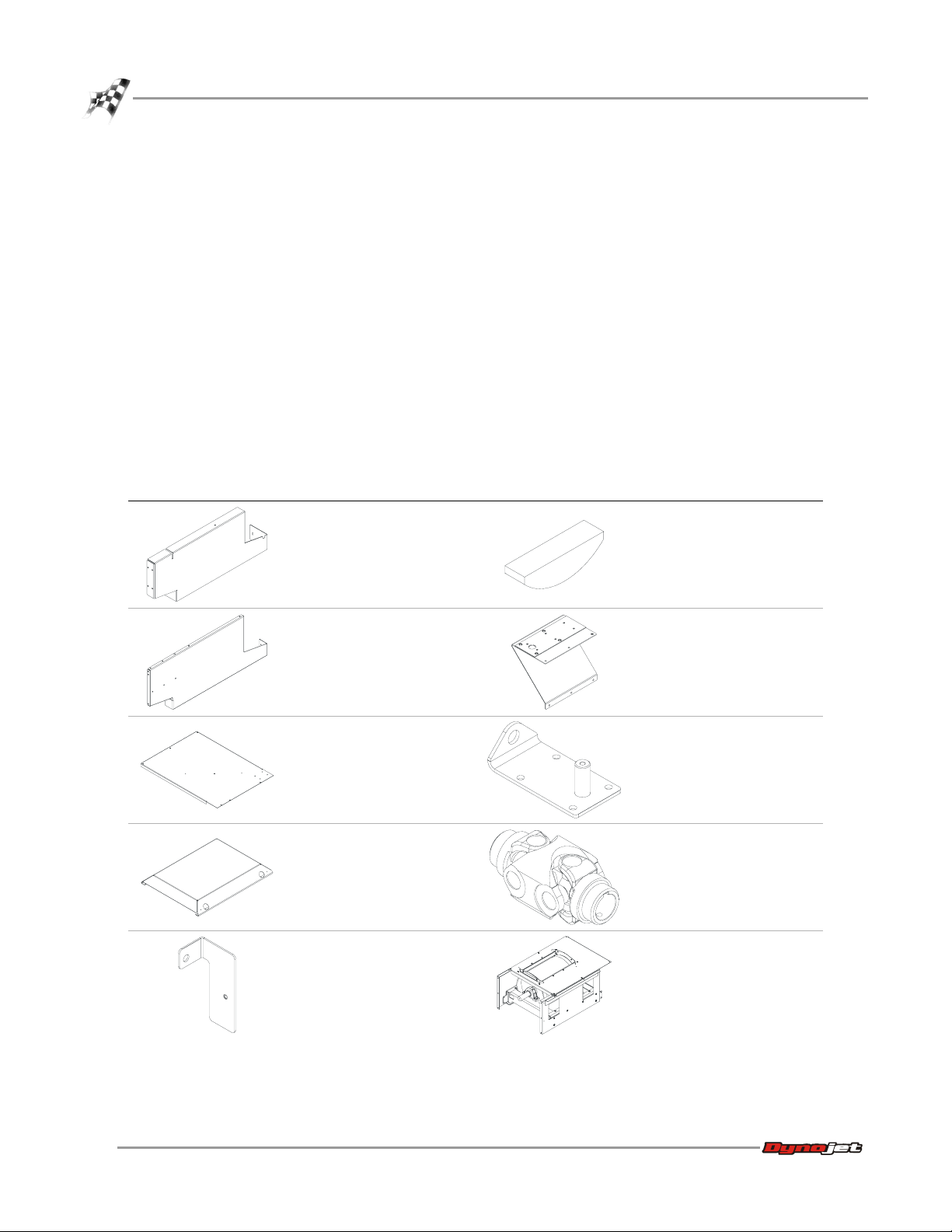
3 Remove the following parts from the crate and set aside.
part description part description
bulkhead support
P/N 21200022
woodruff key, 3/8 x 1-3/8"
P/N 37620622
decking front panel
P/N 21200024
center panel
P/N 21200037
drum safety cover
P/N 21200038
toe kick bracket
P/N 21600012
monitor support brace
P/N 61300007
fan arm mount (2)
P/N 61300009
retarder driveline assembly
P/N 62240070
drum module
P/N 63200001
1-10
Model 200iX/250iX Upgrade Installation Guide
Page 19

MODEL 200IX/250IX UPGRADE
part description part description
lower blower arm (2)
P/N 21600015
trike carriage adapter
assembly
P/N 71300002
Drum Installation
washer, 1.5 x .38 ID x .187
THK (2)
P/N 26215220
washer, 1.87 x 1.25 ID x .25
THK (2)
P/N 26215521
4 Remove the crate braces that support the top portion of the crate.
5 Remove the four lag bolts and washers securing the drum to the crate base using
a 9/16-inch socket, open or box end wrench.
bolt kit
P/N 79100000
Vers ion 1 Model 200iX/250iX Upgrade Installation Guide
1-11
Page 20
CHAPTER 1
Drum Installation
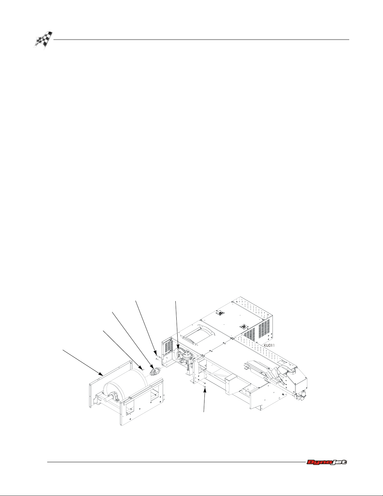
INSTALLING THE IX DRUM MODULE
You will need the following parts:
• 26152030 Spacer
• 36561045 Screw, 1/4-20 x 5/8", PH, Torx (2)
• 37620622 Woodruff Key (2)
• 62240070 Retarder Driveline Assembly
• 63200001 iX Drum Module
1 Remove the drum safety cover from the iX drum module.
2 Remove the six screws securing the iX drum cover and set aside. Remove the
cover and set aside.
3 Place the nylon loop strap around the shaft on either side of the drum module.
4 Using a forklift, lift the drum module from the crate and place the drum module
near the dyno with the stepped end of the shaft towards the dyno. Make sure the
panels on the drum module and the dyno are parallel.
5 Remove the two existing screws (three screws if you have an air pump) from the
dyno frame where the connector plates will attach.
6 Remove the two screws securing the air pump, if present. Refer to Figure 1-8 on
page 1-13.
7 Insert the woodruff key into the keyway on the drum module shaft.
8 Insert the woodruff key into the keyway on the dyno shaft.
9 Slide the driveline over the key on the drum module shaft.
10 Keeping the panels parallel, slide the drum module towards the dyno. Slide the
driveline over the key on the dyno shaft. You will need to support the driveline as
you slide it onto the dyno shaft.
11 Continue sliding the drum module towards the dyno until the side panels on the
drum module and the dyno are flush.
driveline
woodruff key
iX drum module
1-12
Model 200iX/250iX Upgrade Installation Guide
existing screws
Figure 1-7: Installing the Driveline and the Drum Module
woodruff key
existing screws
Page 21
MODEL 200IX/250IX UPGRADE
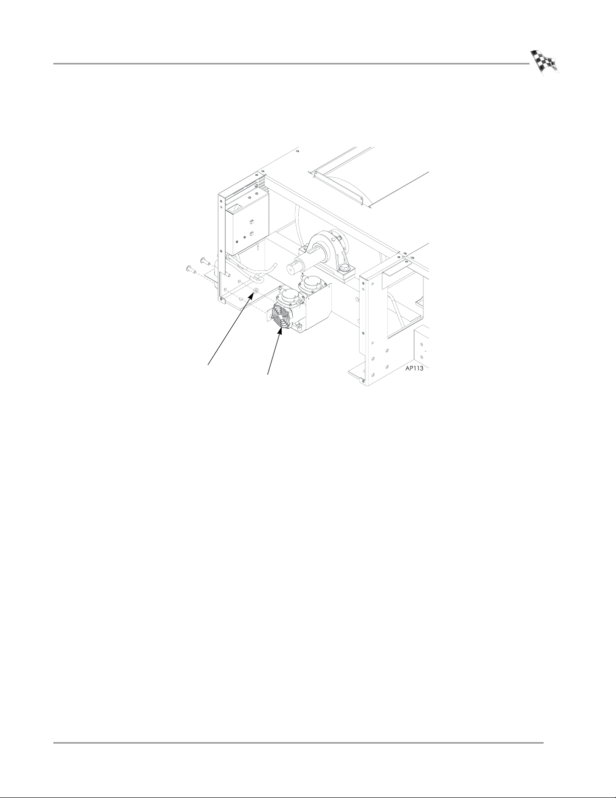
12 Place the air pump spacer (P/N 26152030) as shown in Figure 1-8.
Note: For clarity, the iX drum module is not shown.
Drum Installation
spacer
Figure 1-8: Installing the Air Pump Spacer
air pump
Vers ion 1 Model 200iX/250iX Upgrade Installation Guide
1-13
Page 22

CHAPTER 1
Drum Installation
13 Secure the connector plate on either side of the drum module to the dyno frame
using the screws removed earlier.
14 Verify the panels on the drum module and the dyno line up. These covers must be
flush and parallel. If these covers are not flush, place shims between the floor and
the drum module or the dyno until they are flush.
15 Once aligned, tighten all screws.
16 Secure the side panels on the drum module to the panels on the dyno using one
1/4-20 x 5/8-inch screw.
17 Tighten the driveline set screws.
Note: Dynojet recommends using red loctite on the set screws.
not visible from
this view
1-14
Model 200iX/250iX Upgrade Installation Guide
secure connector plate
Figure 1-9: Securing the Drum Module to the Dyno
Page 23

MODEL 200IX/250IX UPGRADE
BULKHEADS AND COVERS
. . . . . . . . . . . . . . . . . . . . . . . . . . . . . . . . . . .
You will need the following parts:
• 21200022 Middle Bulkhead
• 21200024 Front Bulkhead
• 21600012 Toe Kick Bracket
• 36468100 Nut, 1/4-20, Nylock (5)
• 36561045 Screw, 1/4-20 x 5/8", PH, Torx (16)
• 61300007 Monitor Support Brace
• 76950053 Cable, Fan Power Extension
INSTALLING THE BULKHEADS
1 Place the monitor support brace on the five studs on the front bulkhead.
2 Secure the brace to the studs using five 1/4-20 nylock nuts.
3 Secure the front bulkhead to the dyno frame using four 1/4-20 x 5/8-inch button-
head screws.
4 Secure the middle bulkhead to the dyno frame using five 1/4-20 x 5/8-inch button-
head screws.
Bulkheads and Covers
monitor support
brace
front bulkhead
middle bulkhead
Figure 1-10: Securing the Front and Middle Bulkheads
Vers ion 1 Model 200iX/250iX Upgrade Installation Guide
1-15
Page 24

CHAPTER 1
Bulkheads and Covers
5 Remove the existing 3/8-inch screw from the drum module and secure the toe
6 Attach the blower extension cable to the existing blower cable, disconnected
7 Route the cables removed from the monitor stand over to the left side of the
8 Route any monitor arm cables through the cable pass through.
kick bracket to the drum module.
earlier, by matching up the colors.
dyno.
Note: The monitor stand will be mounted to the left side of the dyno making it
more convenient for motorcycles.
route monitor stand
cables to left side of dyno
and through the cable
pass through
1-16
Model 200iX/250iX Upgrade Installation Guide
toe kick bracket
Figure 1-11: Securing the Toe Kick Bracket
Page 25

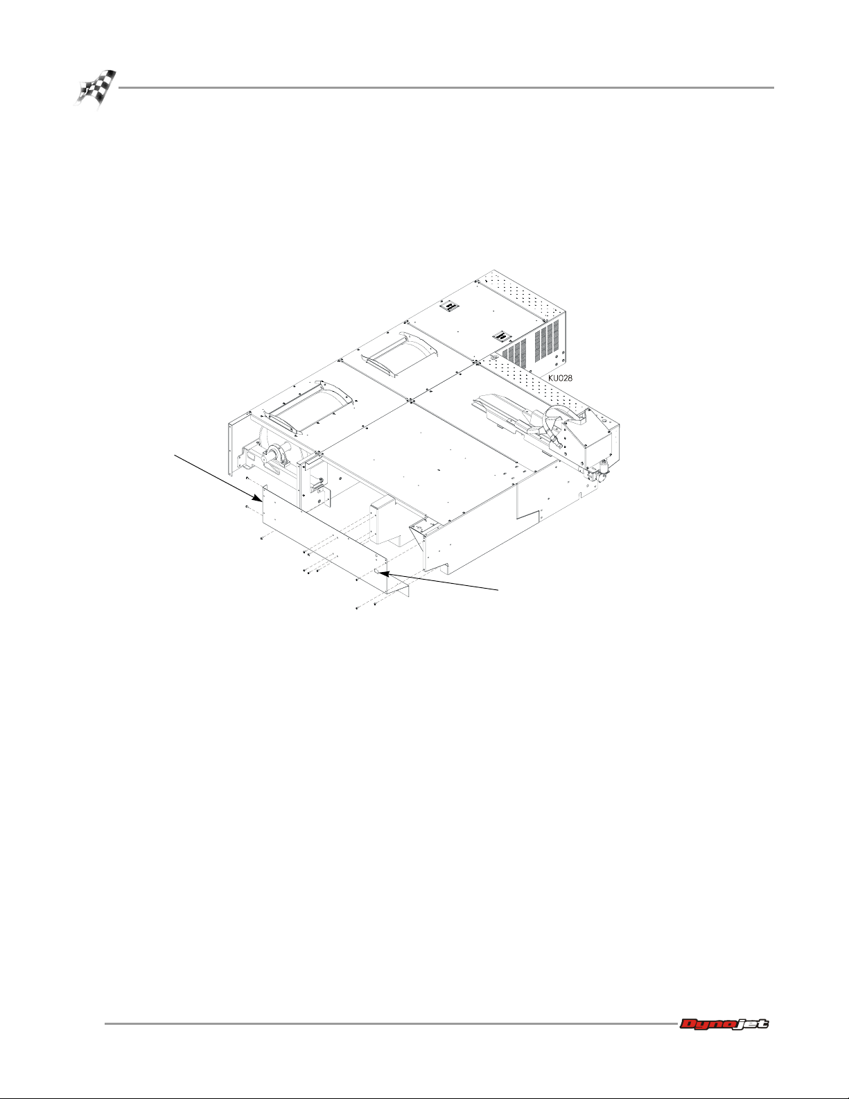
INSTALLING THE PANELS AND COVERS
1 Secure the drum top cover to the drum module using the six 1/4-20 x 5/8-inch
button-head screws removed earlier.
Note: Extra 1/4-20 x 5/8-inch button-head screws are included, should they be
requuired.
drum top cover
MODEL 200IX/250IX UPGRADE
Bulkheads and Covers
Figure 1-12: Securing the Drum Module Top Cover
2 Secure the center panel to the bulkheads using six 1/4-20 x 5/8-inch button-head
screws.
center panel
Figure 1-13: Securing the Center Panel
Version 1 Model 200iX/250iX Upgrade Installation Guide
1-17
Page 26
CHAPTER 1
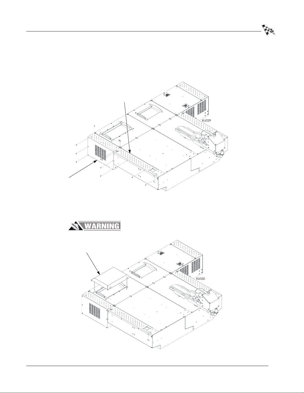
Bulkheads and Covers
dyno side panel
3 Attach the blower extension cable to the fan socket.
• Connect the brown wire to N
• Connect the blue wire to L
• Connect the green/yellow wire to ground
4 Secure the dyno side panel to the bulkheads using the eleven screws removed
earlier.
fan socket
Figure 1-14: Securing the Dyno Side Panel
1-18
Model 200iX/250iX Upgrade Installation Guide
Page 27
MODEL 200IX/250IX UPGRADE
Bulkheads and Covers
5 Secure the dyno top side panel to the bulkheads using the five screws removed
earlier.
6 Secure the drum side cover to the drum module using the eight 1/4-20 x 5/8-inch
button-head screws removed earlier.
dyno top side
panel
drum side cover
Figure 1-15: Securing the Dyno Top Side Panel and Drum Side Cover
7 Place the drum safety cover over the drum. This cover has two pins to keep it in
place.
Risk of injury. Never run a motorcycle on the dyno without this cover in place.
drum safety
cover
Figure 1-16: Installing the Drum Safety Cover
Vers ion 1 Model 200iX/250iX Upgrade Installation Guide
1-19
Page 28

CHAPTER 1
Trike Carriage Adapter Installation
TRIKE CARRIAGE ADAPTER INSTALLATION
. . . . . . . . . . . . . . . . . . . . . . . . . . . . . . . . . . .
Use the following instructions to remove the carriage assembly, install the trike
carriage adapter (P/N 71300002), and replace the carriage assembly.
You will need the following parts:
• 15331100 Chain Lube
• 21200041 Clamp Spacer (3)
• 21200042 Nut Driver Spacer
• 21200045 Trike Carriage Adapter Slide, Rear
• 21200046 Trike Carriage Adapter Slide, Front
• 21200058 Nut Block
• 21200060 Carriage Clamp (3)
• 21200061 Carriage Tie, Left
• 21200062 Carriage Tie, Right
• 35500001 Trike Adapter Plunger
• 36500008 Capscrew, 5/16-UNC x 1”, Button-head (6)
• 36500009 Capscrew, 3/8-16UNC x 1”, Button-head (2)
• 61300013 Trike Carriage Adapter Base
• DM150-002-004 Lock Washer, 5/16" (8)
• DM150-053 Bolt, 5/16-18 x 1", Hex (8)
1-20
Model 200iX/250iX Upgrade Installation Guide
Page 29
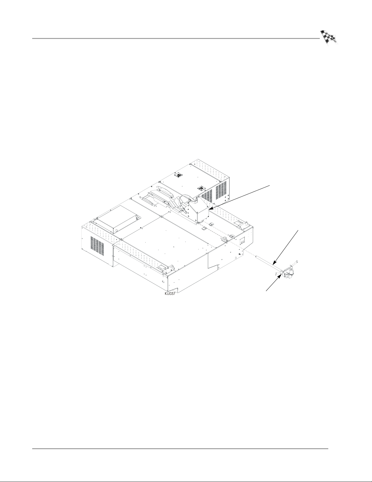
REMOVING THE CARRIAGE SCREW AND CARRIAGE
The monitor stand and high pressure blowers are not shown for clarity.
If the carriage is not installed, skip to “Installing the Trike Carriage Adapter Assembly”
on page 1-23.
1 Remove the four 1/4-20 x 1/2-inch button-head screws securing the bearing
bracket and set aside.
2 Using the hand crank, or the control panel to run the power carriage, run the
carriage screw out of the carriage assembly and set aside.
3 Slide the carriage assembly towards the rear of the dyno. Remove the carriage
assembly and set aside.
MODEL 200IX/250IX UPGRADE
Trike Carriage Adapter Installation
carriage assembly
bearing bracket
Figure 1-17: Removing the Carriage Screw and Carriage
carriage screw
Version 1 Model 200iX/250iX Upgrade Installation Guide
1-21
Page 30
CHAPTER 1
Trike Carriage Adapter Installation
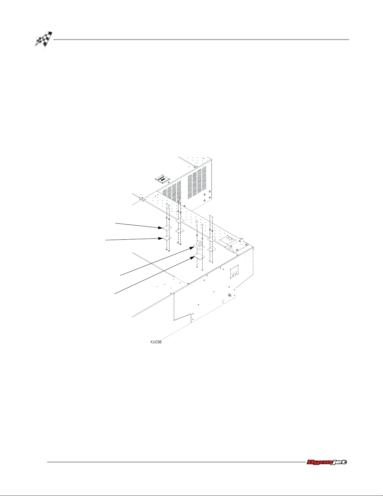
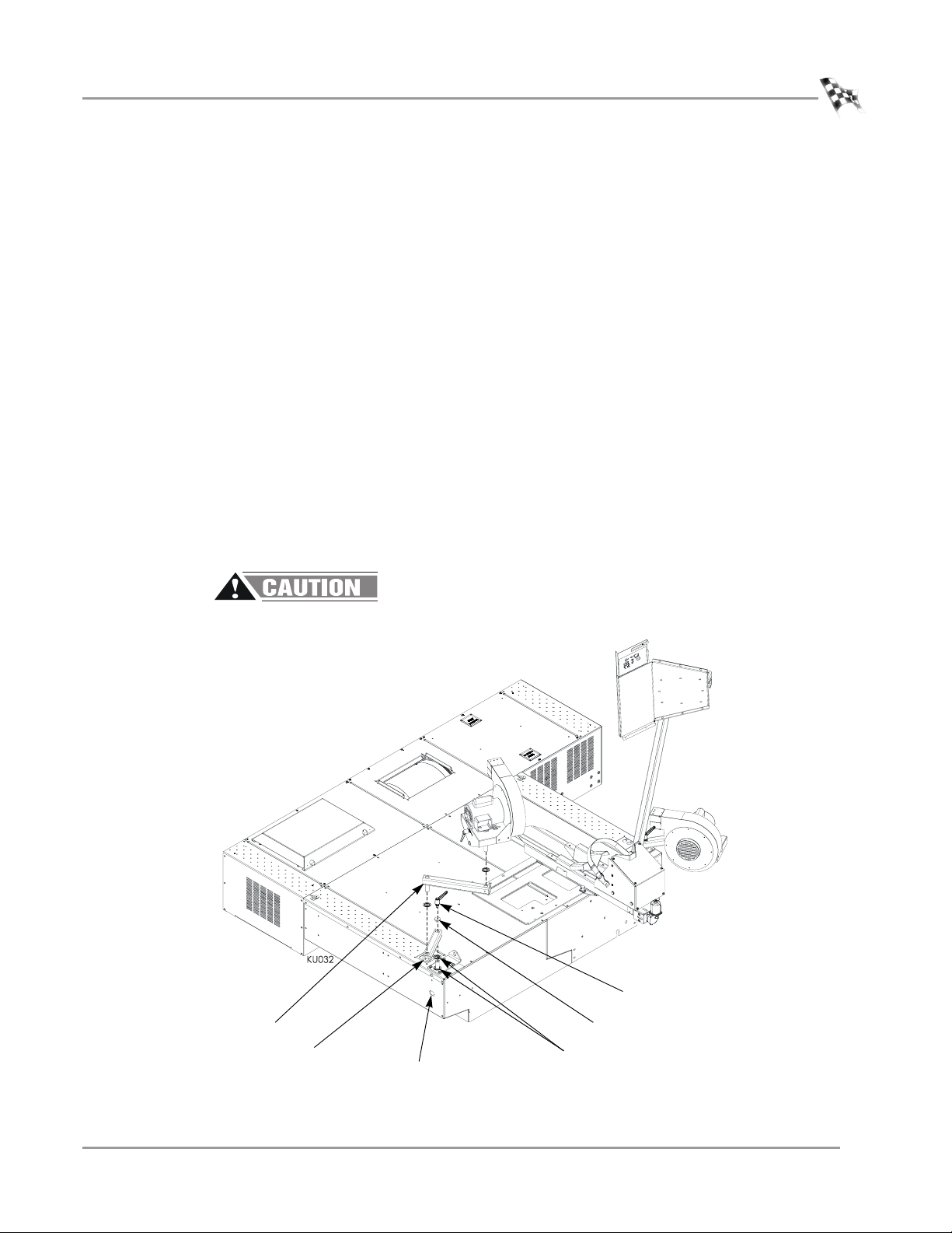
REMOVING THE CARRIAGE CLAMPS, SHIMS, AND NUT BLOCK
If the carriage is not installed, skip to “Installing the Trike Carriage Adapter Assembly”
on page 1-23.
1 Remove the two 5/16 x 1-inch bolts and two 5/16-inch lock washers securing each
carriage clamp and shim and discard. This hardware will not be used.
2 Remove the three carriage clamps and shims and discard. These will not be used.
3 Remove the two 5/16 x 1-inch bolts and two 5/16-inch lock washers securing the
nut block and shim and discard. This hardware will not be used.
4 Remove the nut block and shim and discard. These will not be used.
carriage clamp
shim
nut block
shim
Figure 1-18: Removing the Clamps, Shims, and Nut Block
1-22
Model 200iX/250iX Upgrade Installation Guide
Page 31
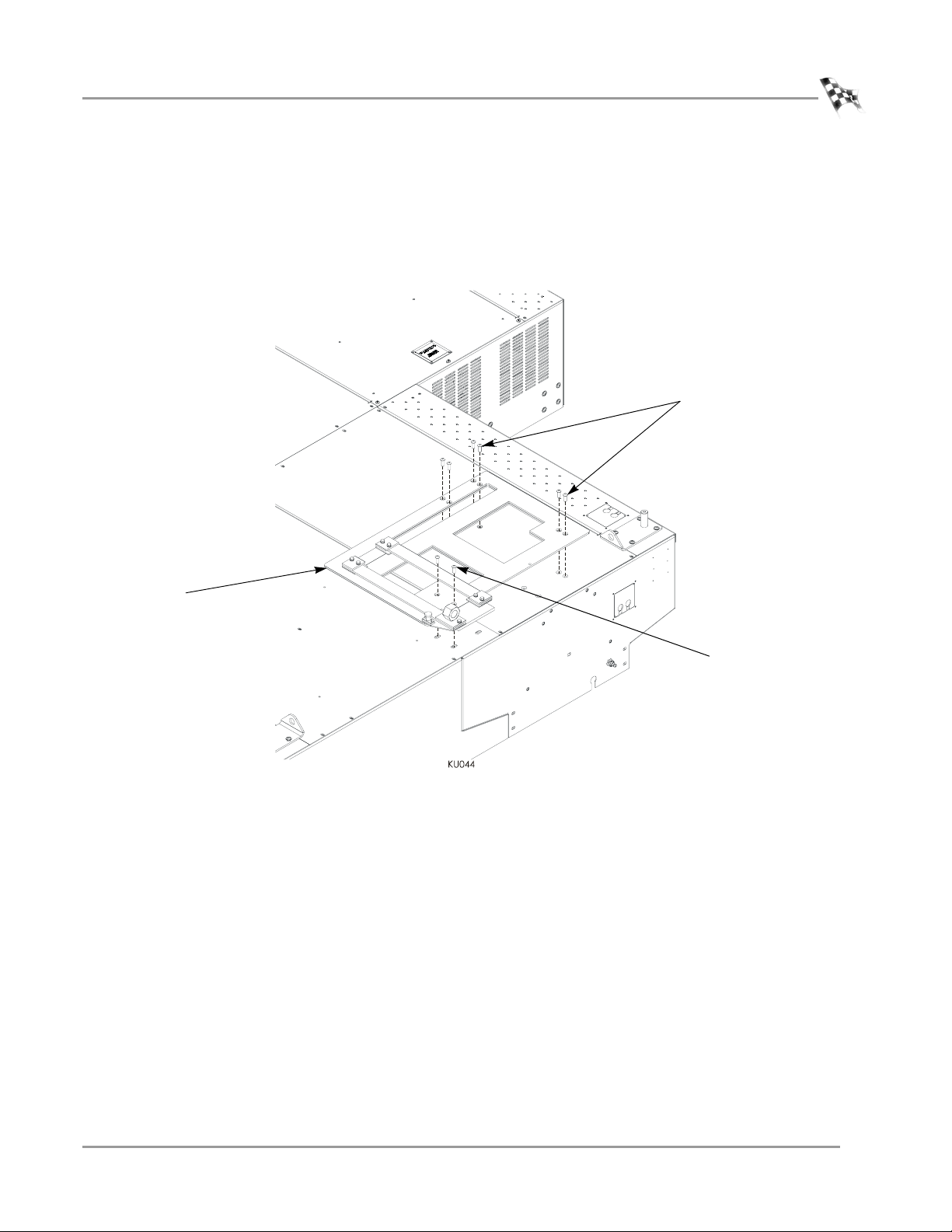
INSTALLING THE TRIKE CARRIAGE ADAPTER ASSEMBLY
1 Secure the trike carriage adapter assembly to the dyno using six 5/16 x 1-inch
button-head bolts where the carriage assembly was installed and two 3/8 x 1-inch
button-head bolts as shown in Figure 1-19.
2 Lube the tracks with the included lube or use grease.
MODEL 200IX/250IX UPGRADE
Trike Carriage Adapter Installation
5/16 x 1-inch bolts
trike carriage
adapter assembly
3/8 x 1-inch bolts
Figure 1-19: Installing the Trike Carriage Adapter Assembly
Vers ion 1 Model 200iX/250iX Upgrade Installation Guide
1-23
Page 32
CHAPTER 1
Trike Carriage Adapter Installation
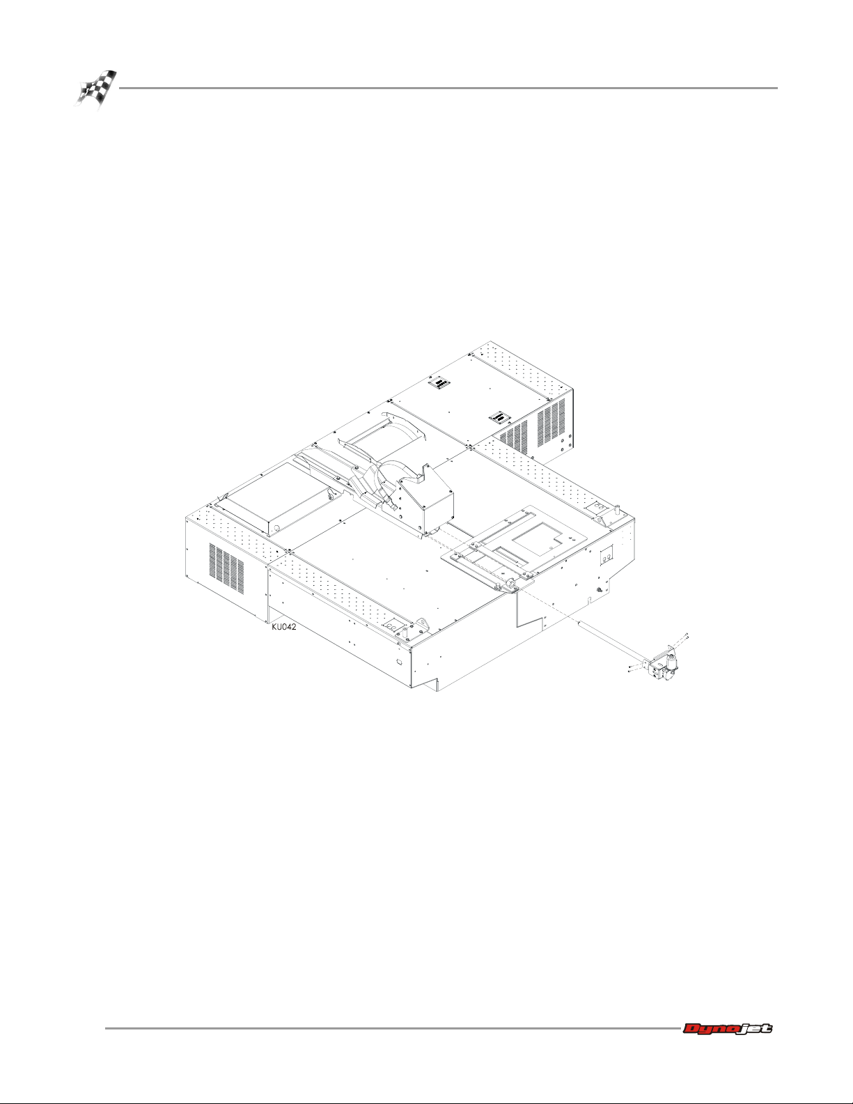
INSTALLING THE CARRIAGE ASSEMBLY
1 Starting from the back of the dyno, slide the carriage under the carriage clamps.
2 Slide the carriage screw and the bearing bracket toward the nut block until the
carriage screw is touching the nut block.
3 Using the hand crank, or the control panel to run the power carriage, run the
carriage screw through the nut block and into the screw support bracket on the
carriage assembly.
4 Secure the bearing bracket to the carriage assembly using the four
1/4-20 x 1/2-inch button-head screws removed earlier.
1-24
Model 200iX/250iX Upgrade Installation Guide
Figure 1-20: Installing the Carriage Assembly
Page 33

MODEL 200IX/250IX UPGRADE
TIE-DOWN INSTALLATION
. . . . . . . . . . . . . . . . . . . . . . . . . . . . . . . . . . .
You will need the following parts:
• 36582034 Bolt, 3/8-16 x 1.25", Button-head, Flange (8)
• 61300009 Tie-Down (2)
1 Install the tie-downs on the right side of the dyno using four 3/8-16 x 1.25-inch
button-head flange screws.
2 Place the tie-down on the left side of the dyno, but do not secure.
Note: Do not secure the tie-down used with the monitor arm until the monitor
arm is in place. Refer to step 1 on page 1-26 for more information.
Tie-Down Installation
tie-down under
monitor support
tie-down on right
side of dyno
Figure 1-21: Installing the Tie-Downs
Vers ion 1 Model 200iX/250iX Upgrade Installation Guide
1-25
Page 34
CHAPTER 1
Monitor Stand and Blowers Installation
MONITOR STAND AND BLOWERS INSTALLATION
. . . . . . . . . . . . . . . . . . . . . . . . . . . . . . . . . . .
You will need the following parts:
• 21600015 Lower Blower Arm (2)
• 26215220 Washer 1.5 x .38 ID x .187 THK (2)
• 26215521 Washer 1.87 x 1.25 ID x .25 THK (2)
• 35712991 Clamp Lever, 3/8-16 x 3/4" (2)
• 76950317 Blower Extension Cord
1 Secure the monitor support to the dyno using the four screws removed earlier.
Note: Make sure the tie-down in sandwiched in between the dyno panel and the
monitor support base.
2 Replace the monitor arms, washers, and tray.
tray
washers
arms
washer
monitor
support
tie-down under
monitor support
1-26
Model 200iX/250iX Upgrade Installation Guide
Figure 1-22: Installing the Monitor Stand
Page 35
MODEL 200IX/250IX UPGRADE
Monitor Stand and Blowers Installation
3 Place a 1/4-inch thick poly washer around the pin on the tie-down with the
monitor arm.
4 Place two 1/4-inch thick poly washers around the pin on the tie-down without the
monitor arm.
5 Replace the existing lower blower arms with the new lower blower arms as shown
in Figure 1-23.
6 Place the new lower blower arm over the pin.
7 Place an aluminum washer between the clamp lever and the lower bower arm.
8 Secure the lower blower arm to the tie-down pin using the clamp lever included
in the upgrade.
9 Place a 1/8-inch thick poly washer around the pin on the upper blower arm.
10 Insert the pin on the upper blower arm into the lower blower arm.
11 Place a 1/8-inch thick poly washer around the pin on the blower.
12 Insert the pin on the blower into the upper blower arm.
13 Plug the power cord from the blower into the power source located on the dyno
chassis.
Note: To allow full extension of the right blower, use the blower extension cord
(P/N 76950317). This extension cord is only used with the blower mounted on
the right side of the dyno.
The blowers can run at any time once the cord is plugged into a power source.
upper blower arm
new lower
blower arm
plug power cord from
blower into dyno chassis
clamp lever
aluminum washer
1/4-inch thick poly washer
use two on non monitor
arm side
Figure 1-23: Installing the Blowers
Vers ion 1 Model 200iX/250iX Upgrade Installation Guide
1-27
Page 36

CHAPTER 1
Ground Hook Installation
GROUND HOOK INSTALLATION
. . . . . . . . . . . . . . . . . . . . . . . . . . . . . . . . . . .
Use the following instructions to install the ground hooks.
You will need the following parts:
• 10111 Ground Hook/D-Ring (4)
• 10112 D-Ring Bracket (4)
• 36932100 Washer, 3/8”, Splitlock, Steel (8)
• 37513200 Anchor, Redhead, 3/8" (8)
• DM150-002-007 Washer, 5/16", Flat (8)
• DM150-019-012 Bolt, 3/8-16 x 1”, Hex (8)
1 Mark the ground hook placement as shown in Figure 1-24. Two additional ground
hooks are included for installation in front of the dyno; placement will vary
depending on dyno application.
2 Using the ground hook as a template, mark and drill each hole needed to secure
the ground hooks to the floor.
3 Install the Red Head anchors. Refer to Appendix A for installation instructions.
4 Secure each ground hook to the floor using two 3/8-16 x 1-inch hex bolts, two
5/16-inch flat washers, and two 3/8” lock washers.
1-28
Model 200iX/250iX Upgrade Installation Guide
Figure 1-24: Ground Hook Placement
Page 37

B
ASIC
D
YNO
C HAPTER
O
PERATION
2
This chapter includes instructions for basic dyno operation. For more detailed
instructions, refer to the WinPEP 7 User Guide. This manual can be found on your
WinPEP CD or at www.dynojet.com.
This chapter is divided into the following categories:
•Loading the Vehicle, page 2-2
• Connecting the RPM Pickup, page 2-4
•Pre-Run Inspection, page 2-7
• Making a Test Run, page 2-9
• Preventative Maintenance, page 2-10
Model 200iX/250iX Upgrade Installation Guide
2-1
Page 38

CHAPTER 2
Loading the Vehicle
LOADING THE VEHICLE
. . . . . . . . . . . . . . . . . . . . . . . . . . . . . . . . . . .
Use the following steps to load a vehicle on the dyno. For detailed information on
loading a motorcycle on the dyno, refer to your motorcycle dyno installation guide.
Risk of injury. Always wear proper eye and ear protection when operating the
dyno.
1 Verify your computer is running. Set the dyno brake on by pressing the red
button on the hand held pendant.
2 For ATVs, slide the carriage to the center position.
3 For trikes, slide the carriage to the centered position that works best for your
particular vehicle.
4 Turn the carriage screw handle (or use the control panel to run the power
carriage) until the carriage is all the way out.
5 Drive the vehicle onto the dyno and align the vehicle straight with the dyno.
6 Stop the vehicle when the drive axle is centered on the drum.
center drive axle
on dyno drum
2-2
Model 200iX/250iX Upgrade Installation Guide
adjust carriage all
the way out
Figure 2-1: Loading the Vehicle
Page 39
BASIC DYNO OPERATION
Loading the Vehicle
7 When the vehicle is positioned properly on the dyno, shut the engine off.
• If the vehicle has an automatic transmission, place it in park.
• If the vehicle has a manual transmission, place it in gear.
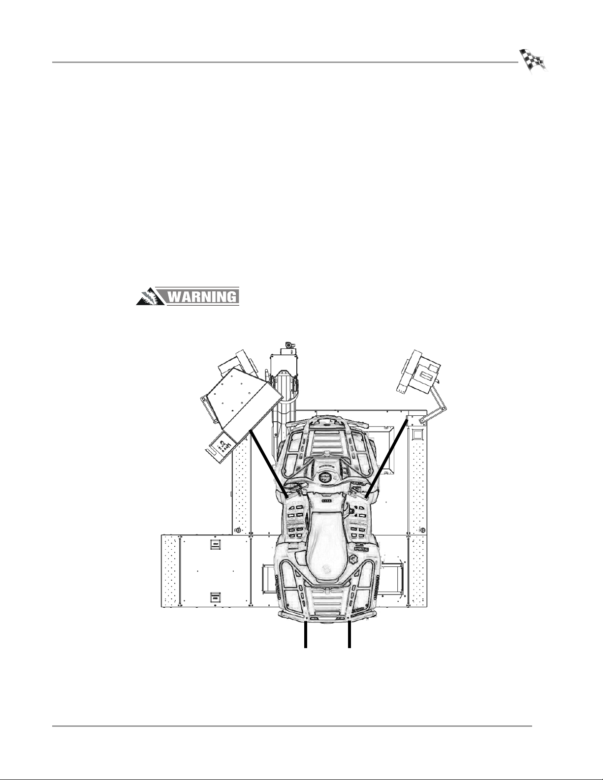
8 Attach two tie-down straps from the anchor points on the ramp, or the ground
hooks, to the rear of the vehicle.
9 Attach two tie-down straps from the anchor points on the dyno to the vehicle
chassis.
Note: If you are running an all wheel drive ATV, use differential jacks to get the
front wheels off the dyno.
Note: When running an ATV, you may need to increase the tire pressure so the
tire does not come in contact with the decking.
10 Tighten the four tie-down straps evenly making sure the drive wheels remain
centered on the drum.
Never perform a dyno run if the tie-down straps are not in place or they are
damaged.
Figure 2-2: Loading the Vehicle—Top View
Vers ion 1 Model 200iX/250iX Upgrade Installation Guide
2-3
Page 40

CHAPTER 2
Connecting the RPM Pickup
CONNECTING THE RPM PICKUP
. . . . . . . . . . . . . . . . . . . . . . . . . . . . . . . . . . .
Your Dynojet dynamometer includes a primary wire inductive pickup and two
secondary wire inductive pickups. These small “clothespin like” inductive pickups are
used to sense RPM. An RPM pickup is required if you want to view torque graphs.
Generally you will use one secondary wire inductive pickup on a spark plug wire.
Vehicles with wasted spark ignition systems may require two secondary inductive
pickups. On a wasted spark ignition, typically one coil will be connected to two spark
plug wires. Attach one secondary pickup to each of these wires. If the pickups are
connected to two plug wires that do not fire at the same time, an erratic RPM readout
may occur. The primary wire inductive pickup senses RPM pulses from the coil.
Although this pickup location generally works better, it is harder to find the correct
location to connect the RPM pickup.
Note: If a pickup is not being used, disconnect it from the dyno electronics to
prevent any stray pick up of signals.
Inductive pickups are very fragile. The ferrite core can easily be damaged and
is not covered under warranty. Dropping, snapping, vibration, and heat can all
damage the ferrite core.
RPM pickup description
Secondaries (Non- wasted spark system) Use one secondary pickup. Unplug the other pickup from the RPM
Secondaries (Wasted spark ignition
system)
Primary pickup Attach the primary wire pickup to the primary side of the coil. Set
The dyno electronics RPM module contains the electronics that sense the RPM pulses.
An auto-gain circuit looks at only the peak voltage of the vehicle’s spark, ignoring the
lower voltages to help reduce electronic noise problems. Wasted spark ignition
systems will produce a lower voltage level on the exhaust stroke than the
compression stroke. By definition of the auto-gain circuit, lower voltage spark levels
will be ignored, missing every other spark the vehicle would produce.
RPM PICKUP DESCRIPTIONS
module and set the degrees between plug fires to 720° in WinPEP 7.
Use two secondary pickups. Attach one pickup on each spark plug
wire on the same coil and set the degrees between plug fires to 360°
in WinPEP 7.
the degrees between plug fires by taking 720 (four cycle engines) or
360 (two cycle engines) divided by the number of coils. For
example, the number of degrees between plug fires on a four
cylinder four cycle engine with dual coils (where each coil fires two
cylinders) is 720/4 x 2 = 360°.
2-4
Model 200iX/250iX Upgrade Installation Guide
Page 41
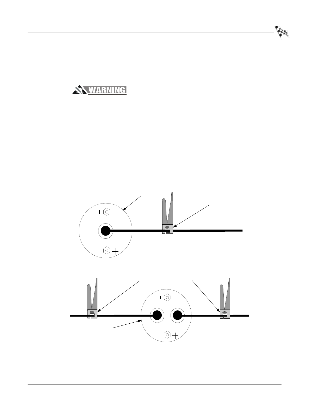
CONNECTING THE SECONDARY INDUCTIVE PICKUP
The secondary inductive pickup cannot be in contact with, or it’s connecting wire be
crossing, other engine electrical wires or stray RF interference may result.
The inductive pickups contain a fragile Ferrite Core that is sensitive to engine
heat and vibration. Do not drop the inductive pickup or snap the pickup
closed. Use extreme care in handling and placement of the pickups.
BASIC DYNO OPERATION
Connecting the RPM Pickup
1 Clip the secondary inductive pickup around one spark plug wire.
Note: On a wasted spark ignition system, two secondary inductive pickup wires
may be needed.
2 Route the inductive pickup cable clear of devices that produce electronic noise
(spark plug wires, coil wire, coil etc.) to the dyno electronics RPM module.
Note: Inductive pickup placement is important. Position the inductive pickup so
that it is not making contact with any other spark plug wires. Separate the spark
plug wire from the spark plug wire bundle for proper operation.
Note: You must ground the vehicle to the dyno for the electronics to function
properly.
coil
Figure 2-3: Connecting the Secondary Inductive Pickup
connect secondary
inductive pickup on
the coil wire
connect secondary inductive
pickup on the coil wires
coil
Figure 2-4: Connecting the Secondary Inductive Pickup
Vers ion 1 Model 200iX/250iX Upgrade Installation Guide
2-5
Page 42

CHAPTER 2
Connecting the RPM Pickup
CONNECTING THE PRIMARY INDUCTIVE PICKUP
The primary inductive pickup cannot be in contact with, or it’s connecting wire be
crossing, other engine electrical wires or stray RF interference may result.
The inductive pickups contain a fragile Ferrite Core that is sensitive to engine
heat and vibration. Do not drop the inductive pickup or snap the pickup
closed. Use extreme care in handling and placement of the pickups.
1 Clip the primary inductive pickup around the wire to the primary side of the coil.
2 Route the primary wire cable clear of devices that produce electronic noise to the
dyno electronics RPM module.
Note: You must ground the vehicle to the dyno for the electronics to function
properly.
coil
Figure 2-5: Connecting the Primary Inductive Pickup
connect primary
inductive pickup on
the negative side of
the coil
2-6
Model 200iX/250iX Upgrade Installation Guide
Page 43

BASIC DYNO OPERATION
PRE-RUN INSPECTION
. . . . . . . . . . . . . . . . . . . . . . . . . . . . . . . . . . .
Perform a vehicle inspection before making a run. Check the following:
• Check the radiator coolant (if applicable) and oil levels.
•Check the fuel source.
• Rotate the drum and check for rocks caught in the tire tread that could fly out.
• For motorcycles, check the chain and the chain master link. Make sure it is
lubricated and adjusted to the proper tension.
• Check the tire pressure and tire speed rating. Improperly inflated tires or
exceeding the maximum speed rating can result in premature wear or severe tire
damage. Make sure the tire has no major deficiencies (cracks in sidewalls, tread life,
etc.).
Note: When running an ATV, you may need to increase the tire pressure so the
tire does not come in contact with the decking.
• Visually inspect the vehicle. Make sure it is in safe running order.
• Make sure ear protection and safety glasses are used when the dyno is being
operated.
• Check the tie-down straps to make sure that they are tight and secured.
• Check the drive tires to be sure that they are aligned correctly on the
dynamometer’s drums.
• Keep all rotating components clear at all times.
• Only the operator should be near the dyno or the vehicle during the test.
Pre-Run Inspection
• Never allow any person(s) to stand behind the dyno or vehicle when it is being
operated.
• Perform any other safety inspections appropriate to running your vehicle on the
dyno.
Never allow any person(s) to stand behind the dyno or vehicle when it is being
operated. Only the operator should be near the dyno or the vehicle during the
test.
Vers ion 1 Model 200iX/250iX Upgrade Installation Guide
2-7
Page 44

CHAPTER 2
Pre-Run Inspection
BEFORE STARTING THE ENGINE
Connect an exhaust hose or hoses (if dual exhaust) on the vehicle, make sure the
hose fits over the tail pipe, is not plugged or kinked and the hose is vented correctly
out of the dyno room.
Engine exhaust contains poisonous carbon monoxide gas. Breathing it could
cause death. Operate machine in well ventilated area.
ENGINE WARM UP
Warm the vehicle’s engine and drivetrain before beginning testing. Consistent engine
temperatures will assure your runs are repeatable.
AFTER ENGINE WARM UP
Always leave the vehicle in neutral (automatic transmission) or in first gear (manual
transmission), with the engine off, and make sure the park brake and the dyno brake
are on when you get off the vehicle on the dyno.
• Fix any fuel, oil, or coolant leaks that may have shown up after engine warm up and
check the carburetor for leaks.
• Any loud or unusual engine noises or excessive exhaust smoke should be resolved
before continuing.
2-8
Model 200iX/250iX Upgrade Installation Guide
Page 45

BASIC DYNO OPERATION
MAKING A TEST RUN
. . . . . . . . . . . . . . . . . . . . . . . . . . . . . . . . . . .
Dyno runs provide safe, reliable road testing right in the shop. The dyno allows you to
measure, record, and diagnose performance problems quickly. The dyno combined
with WinPEP 7 produces consistent, easily interpretable power graphs. Use the
following instructions to ensure repeatable and accurate measurements.
1 Verify the vehicle is secured properly.
2 Place the vehicle in a low gear and release the dyno brake using the hand held
pendant.
3 Slowly accelerate the vehicle to 20 m.p.h.
4 Test the tachometer operation.
4a Rev the engine. The gauges on the computer screen should be moving. If
the tachometer is moving but not registering the correct RPM values, the
number of degrees of revolution of the crank shaft (the plug fires number) is
incorrect.
4b Stop the vehicle, return to the MakeRun Configuration dialog box, and enter
the correct value for the plug firing order.
5 Press the red brake button to apply 100% braking and slow down the vehicle.
Making a Test Run
Using the vehicle’s own brakes to slow or stop the drum at speeds over 30
m.p.h. can severely over heat the brake parts. Dynojet dynamometers with the
air brake or eddy current brake accessory can be used to slow the vehicle and
drum to a full stop at any speed. The vehicle’s brakes should be used in an
emergency stop situation only.
6 Shut the engine off and put the vehicle in gear (manual transmission) or park
(automatic transmission).
7 Set the vehicle’s parking brake and leave the dyno brake on.
8 Perform a final inspection.
• Verify the drive tire’s alignment on the dyno drums.
• Make any adjustments to the tie-down straps as needed.
• Perform any other safety checks that you deem appropriate to your particular
situation.
You are now ready to make a high speed run on the dyno. Refer to your WinPep 7
User Guide for more detailed instructions.
Vers ion 1 Model 200iX/250iX Upgrade Installation Guide
2-9
Page 46

CHAPTER 2
Preventative Maintenance
PREVENTATIVE MAINTENANCE
. . . . . . . . . . . . . . . . . . . . . . . . . . . . . . . . . . .
This section contains basic preventative maintenance and troubleshooting
information for the wheel clamp and CPI fuses.
To maintain proper dynamometer operation, Dynojet recommends you make routine
checks of the dyno.
• Drum—keep the drum clean and keep all objects clear of the drum.
• Brake Pads—check the brake pad clearance regularly. Change the brake pads when
they are worn to less than 0.060 inch thick.
• Air Pump Filter—clean the filter daily or more often depending on usage. Change
the filter when necessary.
• Carriage Slide—keep the carriage slide and screw clean and lightly lubricated.
• Check all air fittings for leaks monthly. Correct any leaks found.
• Once per month verify that the drum brake pressure gauge reads 55 to 65psi
(380 to 450kPa). Adjust regulator if pressure is out of specification.
2-10
Model 200iX/250iX Upgrade Installation Guide
Page 47

R
ED
H
EAD
A PPENDIX
A
A
NCHOR INSTALLATION
This appendix contains instructions for installing the Red Head Multi-Set™II Anchors.
The anchors will be used to secure the dyno to concrete. To ensure safety and
accuracy in the procedures, perform the procedures as they are described. Be sure to
read and understand the warnings included in this appendix.
WARNINGS
Always wear safety glasses and other necessary protective devices or apparel
when installing or working with anchors.
ITW Ramset/Red Head Multi-Set II Anchors are designed to operate properly
only when installed with ITW Ramset/Red Head brand Setting Tools.
The use of a 24 to 40 ounce hammer is recommended for expanding Multi-Set II
anchors.
The use of carbide drill bits manufactured with ANSI B94. 12-77 drill bit diameter
requirements is recommended for installation of this anchor.
Not recommended for use in lightweight masonry material such as block or brick.
Use of core drills is not recommended to drill holes for use with this anchor.
Not recommended for use in new concrete which has not had sufficient time to cure.
Anchor spacing and edge distance requirements (anchor installation locations) are
the responsibility of the engineer of record.
CONTACT INFORMATION FOR ITW RAMSET/RED HEAD
Contact ITW Ramset/Red Head at 1-630-350-0370, or 1300 North Michael Drive,
Wood Dale, IL 60191.
Model 200iX/250iX Upgrade Installation Guide
A-1
Page 48
APPENDIX A
Installation
INSTALLATION
. . . . . . . . . . . . . . . . . . . . . . . . . . . . . . . . . . .
Use the table below to determine the catalog number, drill bit size, minimum hole
depth, and setting tool catalog number.
setting tool
catalog number drill bit size minimum hole depth
Carbon Steel
RM-38/RL-38 (9.5 mm)
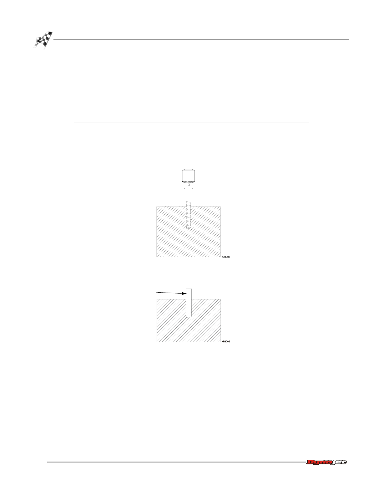
Use the following instructions to install the Red Head anchors.
1 Drill the hole in the concrete the same outside diameter as the anchor being used
to any depth exceeding minimum embedment.
1/2-inch 1 5/8-inch (41.2 mm) RT-138
catalog number
Figure A-1: Red Head Anchor—Drill the Hole
2 Insert the anchor.
anchor
Figure A-2: Red Head Anchor—Insert the Anchor
A-2
Model 200iX/250iX Upgrade Installation Guide
Page 49

RED HEAD ANCHOR INSTALLATION
Installation
3 Using a hammer, drive the anchor flush with the surface of the concrete, or below
the surface if the hole depth exceeds minimum embedment.
Figure A-3: Red Head Anchor—Drive the Anchor Flush
4 Using a hammer, expand the anchor with the setting tool. The anchor is properly
expanded when the shoulder of the setting tool is flush with the top of the
anchor.
Note: Use only Ramset/Red Head setting tools to insure proper installtion.
setting tool
Figure A-4: Red Head Anchor—Expand the Anchor
Vers ion 1 Model 200iX/250iX Upgrade Installation Guide
A-3
Page 50

Page 51

R
AMP
KIT I
A PPENDIX
B
NSTALLATION
This appendix contains instructions for installing the 200iX/250iX ramp kit. To ensure
safety and accuracy in the procedures, perform the procedures as they are described.
Model 200iX/250iX Upgrade Installation Guide
B-1
Page 52

APPENDIX B
Ramp Installation
RAMP INSTALLATION
. . . . . . . . . . . . . . . . . . . . . . . . . . . . . . . . . . .
Verify the dyno ramp is in place and secured to the dyno before beginning with the iX
upgrade ramp installation.
You will need the following parts:
• 21200029 Tie-Down Hook Plate
• 21200039 Ramp Top Cover
• 21200047 Ramp Panel
• 36561045 Screw, 1/4-20 x 5/8”, PH, Torx (8)
• 61300011 Folding Ramp Option
• DM150-020-005 Nut, Crush, 1/4-20 (8)
1 Remove the two existing 3/8-16 x 1.25-inch screws from the back of the iX drum
module.
2 Remove the two existing 1/4-20 x 5/8-inch screws from the top of the iX drum
module.
3 Slide the ramp up to the iX drum module.
4 Secure the ramp to the iX drum module using the screws removed earlier.
dyno ramp
ramp
B-2
Model 200iX/250iX Upgrade Installation Guide
existing screw from the top
of the iX drum module
existing screws from the back of
the iX drum module
Figure B-1: Securing the Ramp to the iX Drum Module
Page 53

RAMP KIT INSTALLATION
Ramp Installation
5 Secure the ramp panel to the iX ramp using four 1/4-20 x 5/8-inch pan-head torx
screws and four 1/4-20 nuts.
6 Secure the ramp panel to the dyno ramp using four 1/4-20 x 5/8-inch pan-head
torx screws and four 1/4-20 nuts.
Note: If the dyno ramp does not have the holes, drill four 1/4-inch holes.
dyno ramp
iX ramp
ramp panel
Figure B-2: Securing the Ramp Panel to the Ramp
Vers ion 1 Model 200iX/250iX Upgrade Installation Guide
B-3
Page 54

APPENDIX B
Ramp Installation
7 Remove the four existing 1/4-20 x 5/8-inch screws from the dyno ramp as shown
in Figure B-3.
8 Remove the two existing 1/4-20 x 5/8-inch screws from the iX ramp as shown in
Figure B-3.
9 Secure the ramp tie-down to the dyno ramp using the four screws removed
earlier.
10 Secure the ramp tie-down to the iX ramp using the two screws removed earlier.
11 Place the ramp cover as shown in Figure B-3.
Note: The ramp cover provides easy access to the air pump filter assembly.
12 Route the air fuel hoses through the large holes in the ramp cover.
ramp tie-down
B-4
Model 200iX/250iX Upgrade Installation Guide
ramp cover
Figure B-3: Securing the Ramp Tie-Down
Page 55

I
NDEX
A
accessories 1-5
air pump spacer 1-13
B
battery hazards iv
blower extension cable 1-16, 1-18
blowers
installing 1-27
removing 1-7
brake pads 2-10
brake pressure 2-10
bulkheads
blower extension cable 1-16
front 1-15
installing 1-15
middle 1-15
monitor support brace 1-15
toe kick bracket 1-16
C
carriage
installing 1-24
removing 1-21
carriage clamps 1-22
center panel 1-17
chassis specifications 1-3
connector plate 1-14
conventions 1-2
crate, removing parts 1-10
D
dimensions 1-4
disclaimers iii
document part number 1-1
driveline 1-12
drum module
air pump spacer 1-13
connector plate 1-14
driveline 1-12
installing 1-12
woodruff key 1-12
drum safety cover 1-19
drum side cover 1-19
drum top cover 1-17
dyno panels
center panel 1-17
drum safety cover 1-19
drum side cover 1-19
drum top cover 1-17
installing 1-17
removing 1-9
side panel 1-18
top side panel 1-19
dyno, specifications 1-3
E
electrostatic discharge iv
ESD precautions iv
F
front bulkhead 1-15
Model 200iX/250iX Upgrade Installation Guide
Index-i
Page 56

INDEX
H
hazards v
height 1-3
I
inspection 2-7
L
length 1-3
loading the vehicle 2-2
M
maintenance 2-10
making a run 2-9
middle bulkhead 1-15
monitor stand
installing 1-26
removing 1-8
monitor support brace 1-15
N
nut block
removing 1-22
P
power, disconnecting 1-6
pre-run inspection 2-7
preventative maintenance 2-10
primary inductive pickup 2-6
S
secondary inductive pickup 2-5
setting tool A-3
shims 1-22
side panel 1-18
spacer, air pump 1-13
specifications
chassis 1-3
length, height, width, weight 1-3
T
technical support 1-2
testing the dyno 2-9
tie-down straps 2-3
tie-downs, installing 1-25
toe kick bracket 1-16
top side panel 1-19
trike carriage adapter
base 1-23
installing 1-23
U
using the dyno 2-9
W
warnings iii
weight 1-3
width 1-3
woodruff key 1-12
R
ramp, installing B-2
red head anchor
contact information A-1
installation A-2
setting tool A-3
warnings A-1
RPM pickup
connecting 2-4
primary inductive pickup 2-6
secondary inductive pickup 2-5
Index-ii
Model 200iX/250iX Upgrade Installation Guide
 Loading...