

Page 1
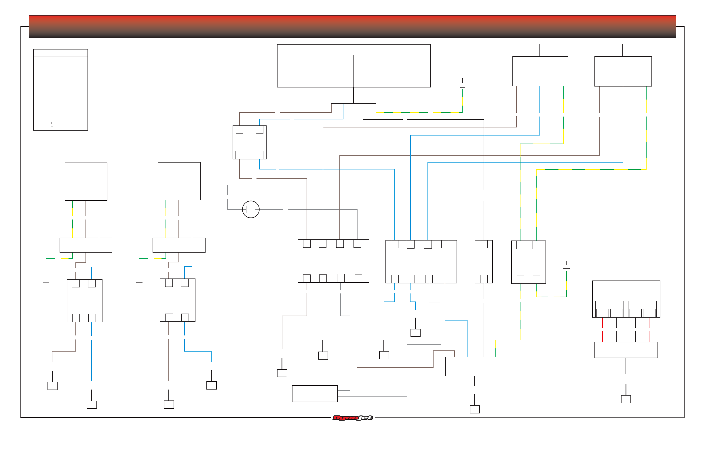
MODEL 200i/200iP/250i/250iP DYNAMOMETER WIRING SCHEMATIC
Legend
BK - Black
BL - Blue
BR - Brown
G - Green
GR - Gray
N - Neutral
N/C - No Connection
O - Orange
R - Red
S - Shield
W - White
Y - Yellow
- Ground
AC socket
right rear dyno
Gr
G/Y
cable, pod right fan
P/N 76950304
G/Y
BR
1
right fan
breaker
3
chassis
N
BR
15A
Wall Outlet
Domestic
240VAC at 60Hz, 30A
single phase w, neutral
BR
BL
1
2
240VAC at 50 Hz, 30A
3 conductor IEC plug
Europe
single phase
G/Y
BK
to 240V theta
controller
cable, retarder driver
P/N 76950305
BR
BL
G/Y
to stack box 240 VAC
50/60 Hz IEC plug
cable, M/C 3 power
P/N 76950310
BR
BL
G/Y
30A
breaker
4
AC socket
left rear dyno
3
BL
BR
chassis
Gr
N
L
BL
G/Y
L
BL
BR
GR
GR
domestic
only
power
indicator
lamp
cable, pod left fan
P/N 76950303
BL
2
G/Y
BR
1
BL
2
15A
left fan
breaker
4
4
3
1
23
brown din rail
2
1
BR
BR
4
3
4
5
blue din rail
5
67
6
7
8
9
10
11
green/yellow
neutral
8
9
din rail
10
11
pod power supply
GR
BR
BL
BL
to CPI board tab 1
BL
GR
BK
G/Y
G/Y
(battery charger)
J1
Pin 1
Pin 2
Pin 4
J2
Pin 5
BR
BL
to CPI board tab 6
8
to CPI board tab 5
8
idynowiring • Version 2 • Page 1 of 2
BL
BR
to CPI board tab 8
7
to CPI board tab 7
7
to CPI board tab 4
3
200iP/250iP only
to CPI board tab 2
5
chassis fan
to CPI board tab 3
4
6
RRBK BK
cable, pod power supply
P/N 76950602
cable, pod AC power
P/N 76950402
to P9 CPI board
to CPI board P13
2
1
© Copyright 2006-2007 Dynojet Research, Inc. All Rights Reserved. 02/2007SD
Page 2
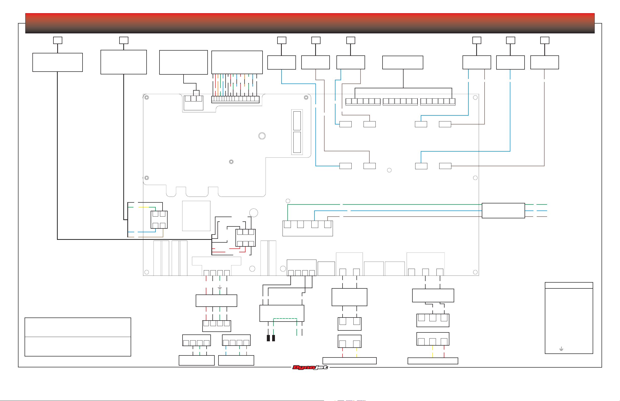
MODEL 200i/200iP/250i/250iP DYNAMOMETER WIRING SCHEMATIC
2 6
cable, pod power supply
P/N 76950602
from pod power supply
1
cable, pod AC power
P/N 76950402
from terminal strip on
power dist. assembly
external e-stop input
pins 1 and 2 jumped
by default when no
external e-stop present
321
**J1
cable, pod button board
P/N 76951501
to control panel button
5-A P1
BK
R
BL
O
BK
W
W
R
G
123456789
G
W
R
W
G
BK
BK
BL
O
BL
W
101112131415
BK
BK
P4
blue wire
S
speed pickup
din rail
P3
out
(N/C)
P1
in
(N/C)
5 8
brown wire
din rail
BL
BR
15A right fan
breaker
BL
BR
tab 5
right fan out
tab 1
AC in right fan
tab 6
tab 2
default: J2 pin 1
jumped to J4 pin 5
6 543216 54321
J4
6 54321
J3
tab 7
left fan out
tab 3
AC in left fan
tab 8
tab 4
J2
7
15A left fan
breaker
BL
BR
blue wire
din rail
BL
34
brown wire
din rail
BR
*Q9 is mounted on the underside and must read
infinite resistance from each pin to the CPI chassis.
If shorted, it will blow the main power fuse, F5.
**Note: At +12 VDC when okay to run. Dyno
shutdown switch or external e-stop switch opens for
dyno shutdown condition turning off all outputs.
idynowiring • Version 2 • Page 2 of 2
G/Y
W
43
P13
BK, from J2
S, N/C other end
12
R, from J2
N
N/C
other end
G
S
R, from J1
BK, from J1
1234
BK
L1
654
BL
BR
F4, AC-L1
F3, AC-L2
P11
from P/N 76950402
from P/N 76950402
R
W
L2
cable, pod air pump
Q9*
N/C
4
32
P2
P9
123
F5
CPI Main Power
W
S
P7
smart brake
E-stop
N/C
BK
F6
main
battery
1234
P/N 76950403
R
4321
connector
1234
N/C
G
WW
to on dyno AFR pump
120 V 60 Hz
G
BK
W
connector
connector
BL
to on dyno AFR pump
240 V 50 Hz
N/C
1234
G
BR
cable, air brake CPI
P/N 76950410
G
W
to brake terminals on
to input wires on
brake solenoid
dyno breakout board
GBK
to power carriage motor assembly
G
BR
1
carriage
2
BK
cable, pod to
power carriage
P/N 76950308
BK
2
2
R
BL
P8
power
connector
connector
1
W
W
1
1
Y
F2
carriage
F1
clamp
P5
tire clamp
2
3
N/C
1
BK
W
cable, pod to clamp
P/N 76950307
BK
N/C
3
connector
connector
3
N/C
to wheel clamp motor assembly
W
1
2
2
1
RY
cable, pod battery
P/N 76950306
P/N 65621600
control panel interface (CPI) board
© Copyright 2006-2007 Dynojet Research, Inc. All Rights Reserved. 02/2007SD
G
to battery - terminal
BL
to starter S terminal
BR
to battery + terminal
N/C - No Connection
Legend
BK - Black
BL - Blue
BR - Brown
G - Green
GR - Gray
N - Neutral
O - Orange
R - Red
S - Shield
W - White
Y - Yellow
- Ground
 Loading...