

Page 1
Page 2
©2003-2006 Dynojet Research, Inc. All Rights Reserved.
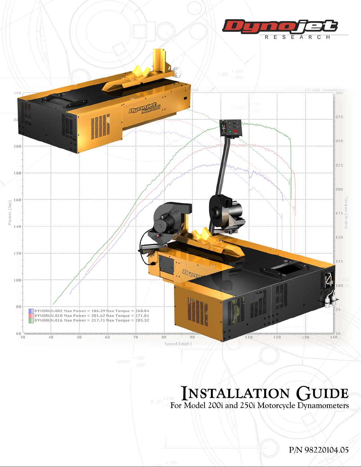
Model 200i and 250i Motorcycle Dynamometer Installation Guide.
This manual is copyrighted by Dynojet Research, Inc., hereafter referred to as Dynojet,
and all rights are reserved. This manual, and the software described in it, is furnished
under license and may only be used or copied in accordance with the terms of such
license. This manual is furnished for informational use only, is subject to change without
notice, and should not be construed as a commitment by Dynojet. Dynojet assumes no
responsibility or liability for any error or inaccuracies that may appear in this manual.
Except as permitted by such license, no part of this manual may be reproduced, stored in
a retrieval system, or transmitted, in any form or by any means, electronic, mechanical,
recording, or otherwise, without the prior written permission of Dynojet.
The Dynojet logo is a trademark of Dynojet Research, Inc.
Any trademarks, trade names, service marks, or service names owned or registered by any
other company and used in this guide are the property of their respective companies.
Dynojet Research, Inc., 2191 Mendenhall Drive, North Las Vegas, Nevada 89081, USA.
Printed in USA.
Part Number: 98220104 Version 5 (5/06)
RECORD
Dynamometer Number: ____________________________________________________
Eddy Current Brake
(Retarder) Number:_________________________________________________________
#
Page 3

T
ABLE OF
C
ONTENTS
Warnings . . . . . . . . . . . . . . . . . . . . . . . . . . . . . . . . . . . . . . . . . . . . . . . .vii
Chapter 1 Specifications and Operating Requirements
Introduction . . . . . . . . . . . . . . . . . . . . . . . . . . . . . . . . . . . . . . . . . . . . . . . . . . 1-2
Conventions Used In This Manual . . . . . . . . . . . . . . . . . . . . . . . . . . . . . . .1-3
Technical Support . . . . . . . . . . . . . . . . . . . . . . . . . . . . . . . . . . . . . . . . . . . 1-3
Your Dyno Room . . . . . . . . . . . . . . . . . . . . . . . . . . . . . . . . . . . . . . . . . . . . 1-3
Dynamometer Specifications and Requirements . . . . . . . . . . . . . . . . . . . .1-5
Battery Requirements . . . . . . . . . . . . . . . . . . . . . . . . . . . . . . . . . . . . . . . . .1-5
Chassis Specifications . . . . . . . . . . . . . . . . . . . . . . . . . . . . . . . . . . . . . . . . . 1-5
Compressed Air Requirements . . . . . . . . . . . . . . . . . . . . . . . . . . . . . . . . . .1-7
Computer Specifications . . . . . . . . . . . . . . . . . . . . . . . . . . . . . . . . . . . . . .1-7
Electrical Requirements . . . . . . . . . . . . . . . . . . . . . . . . . . . . . . . . . . . . . . .1-7
Environmental Requirements . . . . . . . . . . . . . . . . . . . . . . . . . . . . . . . . . . .1-8
Forklift Requirements . . . . . . . . . . . . . . . . . . . . . . . . . . . . . . . . . . . . . . . . . 1-8
Ground Hook Requirements . . . . . . . . . . . . . . . . . . . . . . . . . . . . . . . . . . . 1-8
Phone and Internet Access . . . . . . . . . . . . . . . . . . . . . . . . . . . . . . . . . . . . .1-8
Tie-Down Straps . . . . . . . . . . . . . . . . . . . . . . . . . . . . . . . . . . . . . . . . . . . .1-8
Model 200i Motorcycle Dynamometer . . . . . . . . . . . . . . . . . . . . . . . . . . .1-9
Model 250i Motorcycle Dynamometer . . . . . . . . . . . . . . . . . . . . . . . . . .1-10
Model 200i and 250i Motorcycle Dynamometer Installation Guide
i
Page 4

TABLE OF CONTENTS
Chapter 2 Installation
Dyno Installation . . . . . . . . . . . . . . . . . . . . . . . . . . . . . . . . . . . . . . . . . . . . . . 2-2
Unpacking and Inspecting Your Dyno . . . . . . . . . . . . . . . . . . . . . . . . . . . .2-2
Removing the Dyno from the Crate . . . . . . . . . . . . . . . . . . . . . . . . . . . . . .2-6
Routing the Power Cable . . . . . . . . . . . . . . . . . . . . . . . . . . . . . . . . . . . . . . 2-8
Positioning and Securing the Dyno . . . . . . . . . . . . . . . . . . . . . . . . . . . . . .2-9
Battery . . . . . . . . . . . . . . . . . . . . . . . . . . . . . . . . . . . . . . . . . . . . . . . . . . . . . 2-10
Installing the Battery . . . . . . . . . . . . . . . . . . . . . . . . . . . . . . . . . . . . . . . . 2-10
Pickup Card . . . . . . . . . . . . . . . . . . . . . . . . . . . . . . . . . . . . . . . . . . . . . . . . . 2-11
Eddy Current Brake . . . . . . . . . . . . . . . . . . . . . . . . . . . . . . . . . . . . . . . . . . . 2-12
Parts List . . . . . . . . . . . . . . . . . . . . . . . . . . . . . . . . . . . . . . . . . . . . . . . . . 2-12
Unpacking the Eddy Current Brake . . . . . . . . . . . . . . . . . . . . . . . . . . . . .2-13
Installing the Eddy Current Brake . . . . . . . . . . . . . . . . . . . . . . . . . . . . . . .2-16
Securing the Drum and Brake Module to the Floor . . . . . . . . . . . . . . . . . 2-19
Installing the Theta Controller . . . . . . . . . . . . . . . . . . . . . . . . . . . . . . . . . 2-20
Support Arm and Monitor Tray . . . . . . . . . . . . . . . . . . . . . . . . . . . . . . . . . 2-21
Parts List . . . . . . . . . . . . . . . . . . . . . . . . . . . . . . . . . . . . . . . . . . . . . . . . . 2-21
Installing the Support Arm and Tray . . . . . . . . . . . . . . . . . . . . . . . . . . . . 2-21
Dyno Electronics . . . . . . . . . . . . . . . . . . . . . . . . . . . . . . . . . . . . . . . . . . . . .2-23
Routing Cables . . . . . . . . . . . . . . . . . . . . . . . . . . . . . . . . . . . . . . . . . . . . . .2-25
Routing the Pendant, RS232 Computer Cable, and Control Panel Cable .2-25
Routing the Eddy Current Brake Cables . . . . . . . . . . . . . . . . . . . . . . . . . . 2-30
Wiring the Breakout Board . . . . . . . . . . . . . . . . . . . . . . . . . . . . . . . . . . . .2-31
Routing the Power Carriage and Wheel Clamp Cables . . . . . . . . . . . . . . . 2-32
Tire Carriage Installation . . . . . . . . . . . . . . . . . . . . . . . . . . . . . . . . . . . . . .2-34
Drum Side and Top Covers . . . . . . . . . . . . . . . . . . . . . . . . . . . . . . . . . . . . 2-38
Ramp Bracket . . . . . . . . . . . . . . . . . . . . . . . . . . . . . . . . . . . . . . . . . . . . . . . .2-40
Ground Hooks . . . . . . . . . . . . . . . . . . . . . . . . . . . . . . . . . . . . . . . . . . . . . . .2-43
Zip Tube . . . . . . . . . . . . . . . . . . . . . . . . . . . . . . . . . . . . . . . . . . . . . . . . . . . . 2-44
ii
Model 200i and 250i Motorcycle Dynamometer Installation Guide
Page 5

Chapter 3 Accessories
Main Dyno Power . . . . . . . . . . . . . . . . . . . . . . . . . . . . . . . . . . . . . . . . . . . . . 3-2
Remove and Replace Dyno and Drum Covers . . . . . . . . . . . . . . . . . . . . . .3-3
Removing the Drum Top and Side Covers . . . . . . . . . . . . . . . . . . . . . . . . . 3-3
Removing the Center Panel . . . . . . . . . . . . . . . . . . . . . . . . . . . . . . . . . . . . 3-5
Air Brake . . . . . . . . . . . . . . . . . . . . . . . . . . . . . . . . . . . . . . . . . . . . . . . . . . . . . 3-7
Parts List . . . . . . . . . . . . . . . . . . . . . . . . . . . . . . . . . . . . . . . . . . . . . . . . . . 3-7
Routing the Air Brake Cable and Air Hose . . . . . . . . . . . . . . . . . . . . . . . . . . 3-8
Installing the Emergency Stop Sticker . . . . . . . . . . . . . . . . . . . . . . . . . . . 3-10
Air Brake Final Adjustments and Tests . . . . . . . . . . . . . . . . . . . . . . . . . . .3-14
Changing the Brake Pads . . . . . . . . . . . . . . . . . . . . . . . . . . . . . . . . . . . . .3-15
Adjusting the Brake Pad Clearance . . . . . . . . . . . . . . . . . . . . . . . . . . . . . .3-20
Air Pump and Filter Assembly . . . . . . . . . . . . . . . . . . . . . . . . . . . . . . . . . . 3-21
Parts List . . . . . . . . . . . . . . . . . . . . . . . . . . . . . . . . . . . . . . . . . . . . . . . . . 3-22
Installing the Filter and Pump Assemblies . . . . . . . . . . . . . . . . . . . . . . . . .3-22
Cleaning the Filter Assembly . . . . . . . . . . . . . . . . . . . . . . . . . . . . . . . . . .3-25
Pump Head Maintenance . . . . . . . . . . . . . . . . . . . . . . . . . . . . . . . . . . . . 3-26
Extended Carriage . . . . . . . . . . . . . . . . . . . . . . . . . . . . . . . . . . . . . . . . . . . . 3-28
Parts List . . . . . . . . . . . . . . . . . . . . . . . . . . . . . . . . . . . . . . . . . . . . . . . . . 3-28
Removing the Standard Tire Carriage . . . . . . . . . . . . . . . . . . . . . . . . . . . 3-29
Installing the Extended Carriage Support Bracket . . . . . . . . . . . . . . . . . . .3-31
Installing the Extended Carriage . . . . . . . . . . . . . . . . . . . . . . . . . . . . . . .3-34
High Pressure Blower . . . . . . . . . . . . . . . . . . . . . . . . . . . . . . . . . . . . . . . . .3-38
Parts List . . . . . . . . . . . . . . . . . . . . . . . . . . . . . . . . . . . . . . . . . . . . . . . . . 3-38
Installing the Blower Arm Assemblies . . . . . . . . . . . . . . . . . . . . . . . . . . . .3-39
Installing the High Pressure Blower Assemblies . . . . . . . . . . . . . . . . . . . . .3-40
Connecting Power to the Blowers . . . . . . . . . . . . . . . . . . . . . . . . . . . . . .3-41
Power Carriage . . . . . . . . . . . . . . . . . . . . . . . . . . . . . . . . . . . . . . . . . . . . . .3-42
Parts List . . . . . . . . . . . . . . . . . . . . . . . . . . . . . . . . . . . . . . . . . . . . . . . . . 3-42
Removing the Hand Crank . . . . . . . . . . . . . . . . . . . . . . . . . . . . . . . . . . . .3-43
Installing the Power Carriage . . . . . . . . . . . . . . . . . . . . . . . . . . . . . . . . . .3-44
Wheel Clamp . . . . . . . . . . . . . . . . . . . . . . . . . . . . . . . . . . . . . . . . . . . . . . . . 3-47
Final Adjustments and Tests . . . . . . . . . . . . . . . . . . . . . . . . . . . . . . . . . . . .3-49
Turning On the Dyno Power . . . . . . . . . . . . . . . . . . . . . . . . . . . . . . . . . .3-49
Power Carriage Final Adjustments and Tests . . . . . . . . . . . . . . . . . . . . . . 3-49
Wheel Clamp Final Adjustments and Tests . . . . . . . . . . . . . . . . . . . . . . . .3-49
TAB LE OF CONT ENTS
Version 5 Model 200i and 250i Motorcycle Dynamometer Installation Guide
iii
Page 6

TABLE OF CONTENTS
Chapter 4 Control Panel Interface Operation
Introduction . . . . . . . . . . . . . . . . . . . . . . . . . . . . . . . . . . . . . . . . . . . . . . . . . . 4-2
Basic Control Panel Operation . . . . . . . . . . . . . . . . . . . . . . . . . . . . . . . . . . .4-3
Using the Air Fuel Ratio Air Pump . . . . . . . . . . . . . . . . . . . . . . . . . . . . . . . 4-4
Using the Emergency Stop/Dyno Shutdown . . . . . . . . . . . . . . . . . . . . . . .4-5
Using the High Pressure Blowers . . . . . . . . . . . . . . . . . . . . . . . . . . . . . . . .4-5
Understanding Interlocks . . . . . . . . . . . . . . . . . . . . . . . . . . . . . . . . . . . . . . 4-5
Using the Power Carriage . . . . . . . . . . . . . . . . . . . . . . . . . . . . . . . . . . . . . 4-6
Using the Starter . . . . . . . . . . . . . . . . . . . . . . . . . . . . . . . . . . . . . . . . . . . .4-6
Using the Status Indicator . . . . . . . . . . . . . . . . . . . . . . . . . . . . . . . . . . . . . 4-7
Using the Wheel Clamp . . . . . . . . . . . . . . . . . . . . . . . . . . . . . . . . . . . . . . . 4-7
Power Distribution Assembly . . . . . . . . . . . . . . . . . . . . . . . . . . . . . . . . . . . . 4-9
Main Dyno Circuit Breaker . . . . . . . . . . . . . . . . . . . . . . . . . . . . . . . . . . . . .4-9
High Pressure Blower Circuit Breakers . . . . . . . . . . . . . . . . . . . . . . . . . . . .4-9
Maintenance and Troubleshooting . . . . . . . . . . . . . . . . . . . . . . . . . . . . . .4-10
Wheel Clamp . . . . . . . . . . . . . . . . . . . . . . . . . . . . . . . . . . . . . . . . . . . . . . 4-10
Replacing the Theta Controller Fuses . . . . . . . . . . . . . . . . . . . . . . . . . . . .4-11
Troubleshooting CPI Fuses . . . . . . . . . . . . . . . . . . . . . . . . . . . . . . . . . . . .4-12
Chapter 5 Basic Dyno Operation
Loading the Bike . . . . . . . . . . . . . . . . . . . . . . . . . . . . . . . . . . . . . . . . . . . . . . 5-2
Connecting the RPM Pickup . . . . . . . . . . . . . . . . . . . . . . . . . . . . . . . . . . . . 5-4
RPM Pickup Descriptions . . . . . . . . . . . . . . . . . . . . . . . . . . . . . . . . . . . . . . 5-4
Connecting the Primary Inductive Pickup . . . . . . . . . . . . . . . . . . . . . . . . . 5-5
Connecting the Secondary Inductive Pickup . . . . . . . . . . . . . . . . . . . . . . .5-7
Pre-run Inspection . . . . . . . . . . . . . . . . . . . . . . . . . . . . . . . . . . . . . . . . . . . . .5-9
Before Starting the Engine . . . . . . . . . . . . . . . . . . . . . . . . . . . . . . . . . . . .5-10
Engine Warm Up . . . . . . . . . . . . . . . . . . . . . . . . . . . . . . . . . . . . . . . . . . . 5-10
After Engine Warm Up . . . . . . . . . . . . . . . . . . . . . . . . . . . . . . . . . . . . . . .5-10
Making a Test Run . . . . . . . . . . . . . . . . . . . . . . . . . . . . . . . . . . . . . . . . . . . 5-11
Preventative Maintenance . . . . . . . . . . . . . . . . . . . . . . . . . . . . . . . . . . . . .5-12
Appendix A Red Head Anchor Installation
Warnings . . . . . . . . . . . . . . . . . . . . . . . . . . . . . . . . . . . . . . . . . . . . . . . . . . . .A-1
Contact Information for ITW Ramset/Red Head . . . . . . . . . . . . . . . . . . . . .A-1
Installation . . . . . . . . . . . . . . . . . . . . . . . . . . . . . . . . . . . . . . . . . . . . . . . . . . .A-2
iv
Model 200i and 250i Motorcycle Dynamometer Installation Guide
Page 7

Appendix B Power Requirements
Locations Using 60Hz Power (North America & Japan) . . . . . . . . . . . . . . B-2
Installing the Wall Receptacle . . . . . . . . . . . . . . . . . . . . . . . . . . . . . . . . . . .B-3
Testing for Correct Voltages . . . . . . . . . . . . . . . . . . . . . . . . . . . . . . . . . . . .B-4
Replacing the Power Plug . . . . . . . . . . . . . . . . . . . . . . . . . . . . . . . . . . . . .B-5
Hard Wiring to the Building . . . . . . . . . . . . . . . . . . . . . . . . . . . . . . . . . . . .B-5
Connecting the Dyno . . . . . . . . . . . . . . . . . . . . . . . . . . . . . . . . . . . . . . . .B-6
Locations Using 50 Hz Power
(Locations Other than North America and Japan) . . . . . . . . . . . . . . . . . . . B-7
Installing the Wall Receptacle . . . . . . . . . . . . . . . . . . . . . . . . . . . . . . . . . . .B-8
Testing for Correct Voltages . . . . . . . . . . . . . . . . . . . . . . . . . . . . . . . . . . . .B-9
Replacing the Power Plug . . . . . . . . . . . . . . . . . . . . . . . . . . . . . . . . . . . .B-10
Hard Wiring to the Building . . . . . . . . . . . . . . . . . . . . . . . . . . . . . . . . . . .B-10
Connecting the Dyno . . . . . . . . . . . . . . . . . . . . . . . . . . . . . . . . . . . . . . .B-11
Appendix C Theta Controller
Power Adjustment . . . . . . . . . . . . . . . . . . . . . . . . . . . . . . . . . . . . . . . . . . . . .C-2
Accessing the Dip Switches . . . . . . . . . . . . . . . . . . . . . . . . . . . . . . . . . . . .C-2
TAB LE OF CONT ENTS
Appendix D EEC Kit
EEC Finger Guards Installation . . . . . . . . . . . . . . . . . . . . . . . . . . . . . . . . . . D-2
Removing the Drum Module Hood . . . . . . . . . . . . . . . . . . . . . . . . . . . . . D-2
Installing the EEC Finger Guards . . . . . . . . . . . . . . . . . . . . . . . . . . . . . . . D-3
Adjusting the EEC Finger Guards . . . . . . . . . . . . . . . . . . . . . . . . . . . . . . . D-5
Door Safety Switch . . . . . . . . . . . . . . . . . . . . . . . . . . . . . . . . . . . . . . . . . . . D-6
Installing the Door Safety Switch . . . . . . . . . . . . . . . . . . . . . . . . . . . . . . . D-6
Appendix E Standard and Extended Tire Carriage Installation—
Discontinued
Standard Tire Carriage—Discontinued . . . . . . . . . . . . . . . . . . . . . . . . . . . . E-2
Installing the Standard Tire Carriage . . . . . . . . . . . . . . . . . . . . . . . . . . . . . E-2
Extended Tire Carriage—Discontinued . . . . . . . . . . . . . . . . . . . . . . . . . . . . E-6
Installing the Extended Tire Carriage Support Bracket . . . . . . . . . . . . . . . . E-6
Installing the Extended Tire Carriage . . . . . . . . . . . . . . . . . . . . . . . . . . . . . E-9
Index . . . . . . . . . . . . . . . . . . . . . . . . . . . . . . . . . . . . . . . . . . . . . . . . . . . Index-i
Version 5 Model 200i and 250i Motorcycle Dynamometer Installation Guide
v
Page 8

Page 9

W
ARNINGS
Disclaimers
Dynojet Research, Inc. (Dynojet) makes no representation or warranties with respect to the contents
hereof and specifically disclaims any implied warranties of merchantability for any particular purpose.
Dynojet reserves the right to revise this publication and to make changes from time to time in the
content hereof without obligation of Dynojet to notify any person of such revision or changes.
Dynojet is not responsible for false operation due to unexpected dynamometer operation such as may
be caused by static, software bugs, hardware failure, etc.
Dynojet is not responsible for damage resulting from improper installation of the dynamometer or
from improper service rendered to the dynamometer. Dynojet is not responsible for damage incurred
due to alteration of the dynamometer or components, use of unapproved parts, or abuse to the
dynamometer.
Do not connect or disconnect cables or components on the dynamometer with the power on.
Always wear protective clothing, ear protection, and eye protection (goggles, safety glasses) when
using and servicing the dynamometer.
Equipment Power Requirements
The dynamometer has specific power requirements and instructions that must be followed for proper
operation. Power requirements and installation can be found in Appendix B. Failure to follow these
instructions could result in personal injury or damage to the dynamometer. Connecting the
dynamometer to the incorrect voltage will void the dynamometer warranty. Installation may require
a licensed electrician.
Potentially Lethal Voltages
Components attached to and within the dynamometer operate with potentially lethal voltages. To
provide the greatest assurance of safety, the AC power cord(s) must be disconnected from the power
source before servicing electrical components or wiring. Disconnect all power cords before servicing
electrical components for the greatest assurance of safety.
Model 200i and 250i Motorcycle Dynamometer Installation Guide
vii
Page 10
WARN INGS
Electrostatic Discharge Precautions
Electrostatic Discharge
Electrostatic Discharge (ESD), or static shock, can damage electronic components within the
dynamometer. The damage may occur at the time of an ESD occurrence, or the shock may degrade
the component, resulting in a premature component failure later. To avoid ESD damage, always
practice good ESD control precautions when servicing the dynamometer. Dynojet designs its
dyn amo me ter s t o be ver y t ole ran t o f st ati c sh oc ks by the users, but the electronics are vulnerable when
the electronics are exposed. ESD occurs as a result of a difference of potential between two objects
when the two objects touch. Damage occurs as a result of the energy released when the discharge
(touch) occurs. The difference of potential can accumulate by as simple an action as a user moving
across carpet or a seat. If that person’s energy is discharged directly to the electronics, the electronics
can be damaged.
Precautions
To protect against ESD damage, you must eliminate the difference of potential before the electronics
are handled. Touch the chassis of the dynamometer before touching any of the electronics. By touching
the chassis, you discharge any static shocks to the chassis instead of to the electronics.
If you are holding a circuit board or dynamometer component in your hand when you approach the
machine, touch the chassis of the dynamometer with your hand before installing the circuit board or
component.
When handling a circuit board or component to someone, touch that person with your hand first,
then hand them the component.
Always carry circuit boards in anti-static bags when the boards are exposed (removed from the
dynamometer).
Battery Fire and Explosion Hazards
There is a danger of explosion if the battery is incorrectly replaced. Replace only with the same or
equivalent type recommended by the manufacturer. Discard used batteries according to the
manufacturer’s instructions.
Automotive Batteries
In operation, batteries generate and release flammable hydrogen gas. They must always be assumed
to contain this gas which, if ignited by burning cigarette, naked flame or spark, may cause battery
explosion with dispersion of casing fragments and corrosive liquid electrolyte. Carefully follow
manufacturer's instructions for installation and service. Keep away all sources of gas ignition and do
not allow metallic articles to simultaneously contact the negative and positive terminals of a battery.
Do not allow the positive and negative terminals to short-circuit. The dynamometer chassis is tied to
the negative side of the battery. Do not short between the positive battery terminal or the starter
connections to the chassis. In addition, make sure metal tools such as screw drivers, wrenches, and
torque wrenches do not come in contact with the negative and positive terminals of the battery. Short
circuiting the terminals of the battery can cause burn injuries, damage to the dynamometer, or trigger
explosions.
Charging
Batteries being charged will generate and release flammable hydrogen gas. Charging space should be
ventilated. Keep battery vent caps in position. Prohibit smoking and avoid creation of flames and sparks
nearby.
Wear protective clothing, eye and face protection, when charging or handling batteries.
viii
Model 200i and 250i Motorcycle Dynamometer Installation Guide
Page 11

WARNINGS
Other Potential Hazards
The AC power outlet shall be installed near the equipment and it shall be easily accessible to allow for
disconnect before service.
The dynamometer should be located in a well ventilated area. There is a carbon monoxide hazard with
all internal combustion engines. Engine exhaust contains poisonous carbon monoxide gas. Breathing
it could cause death.
Always wear proper ear and eye protection when operating the dynamometer.
Never operate the dynamometer with the covers removed.
Never stand behind the dynamometer when in operation.
Never operate the dynamometer when there is excessive vibration or noise. Resolve these problems
before proceeding.
Verify brake operation before beginning any dynamometer testing.
Verify the vehicle is properly secured to the dynamometer.
Never operate the blowers without the guards installed.
Exercise care with any dynamometer testing; portions of the dynamometer and vehicle may become
hot.
As with any equipment using electricity and having moving parts, there are potential hazards. To use
this dynamometer safely, the operator should become familiar with the instructions for operation of
the dynamometer and always exercise care when using it.
Do not repair or replace any part of the dynamometer or attempt any servicing unless specifically
recommended in published user-repair instructions that you understand and have the skills to carry
out.
Version 5 Model 200i and 250i Motorcycle Dynamometer Installation Guide
ix
Page 12

Page 13

C HAPTER
S
PECIFICATIONS AND
Thank you for purchasing Dynojet’s Model 200i/250i Motorcycle Dynamometer.
Dynojet’s software and dynamometers will give you the power to get the maximum
performance out of vehicles you evaluate. Whether you are new to the benefits of a
chassis dynamometer or an experienced performance leader, the repeatability and
diagnostic tools of WinPEP 7 software and a Dynojet dynamometer will give you the
professional results you are looking for.
This document provides instructions for installing the Dynojet’s Model 200i/250i
Motorcycle Dynamometer (dyno). This document will walk you through operating
requirements, installation, accessories, and basic dyno operation. To ensure safety
and accuracy in the procedures, perform the procedures as they are described.
Document Part Number: 98220104
O
PERATING
R
EQUIREMENTS
1
Versio n 5
Last Updated: 4-13-06
This chapter is divided into the following categories:
•Introduction, page 1-2
• Dynamometer Specifications and Requirements, page 1-5
• Model 200i Dynamometer, page 1-9
• Model 250i Dynamometer, page 1-10
Model 200i and 250i Motorcycle Dynamometer Installation Guide
1-1
Page 14
CHAPTER 1
Introduction
INTRODUCTION
. . . . . . . . . . . . . . . . . . . . . . . . . . . . . . . . . . .
Before installing your dyno, please take a moment to read this guide for installation
instructions, dyno features, and other important information.
This guide is designed to be a reference tool in your everyday work and includes the
following chapters and information:
SPECIFICATIONS AND OPERATING REQUIREMENTS
This chapter describes the requirements and specifications for the dyno.
INSTALLATION
This chapter describes the procedures for installing the dyno.
ACCESSORIES
This chapter lists each dyno accessory alphabetically and describes the procedures for
installing and using the accessory.
CONTROL PANEL INTERFACE OPERATION
This chapter describes the control panel interface (CPI) operating procedures.
BASIC DYNO OPERATION
This chapter describes basic dyno operating procedures.
RED HEAD INSTALLATION
This appendix describes the procedures for installing the Red Head anchors.
POWER REQUIREMENTS
This appendix describes the power requirements and installation instructions for all
locations.
THETA CONTROLLER
This appendix describes how to make power adjustments to the theta controller.
EEC KIT
This appendix describes the procedures for installing the EEC finger guards and door
safety switch.
STANDARD AND EXTENDED TIRE CARRIAGE INSTALLATION—DISCONTINUED
This appendix describes the procedures for installing the standard and extended tire
carriage without the easy removal bracket.
1-2
Model 200i and 250i Motorcycle Dynamometer Installation Guide
Page 15
SPECIFICATIONS AND OPERATING REQUIREMENTS
CONVENTIONS USED IN THIS MANUAL
The conventions used in this manual are designed to protect both the user and the
equipment.
example of convention description
The Caution icon indicates a potential hazard to the
dynamometer equipment. Follow all procedures
exactly as they are described and use care when
performing all procedures.
The Warning icon indicates potential harm to the
person performing a procedure and/or the
dynamometer equipment.
The Record # icon reminds you to record your
RECORD
#
dynamometer and/or eddy current brake (retarder)
number on the inside cover of this manual.
Introduction
Bold
!
TECHNICAL SUPPORT
For assistance, please contact Dynojet Technical Support at 1-800-992-3525, or write
to Dynojet at 2191 Mendenhall Drive, North Las Vegas, NV 89081.
Visit us on the World Wide Web at www.dynojet.com where Dynojet provides state of
the art technical support, on-line shopping, 3D visualizations, and press releases
about our latest product lines.
YOUR DYNO ROOM
This section is not meant to imply that a dyno room is essential to repeatable results
on a Dynojet dynamometer. However, a dyno room with an engine cooling intake fan,
exhaust extraction, and noise reduction capabilities can add a new dimension to your
shop.
A proper dyno room design will help to ensure repeatable, accurate runs. A good
dyno room should do the following:
• minimize noise
• provide a controlled environment for testing
• provide a view window (safety glass) for customers
Highlights items you can select on in the software
interface, including buttons and menus.
The arrow indicates a menu choice. For example,
“select
File !Open” means “select the File menu,
then select the
Open choice on the File menu.”
• be designed with safety in mind
Intake Air Fan—After building your dyno room, you will need to supply an intake air
fan. The intake air fan supplies air to cool the bike’s engine while supplying fresh
oxygen for you and your bike to breathe. It is a common misconception that you
cannot tune a bike without a large fan simulating exact road conditions; however, a
good cooling fan is the only requirement for consistent diagnostics and tuning. The
installed fan should be 5200 CFM.
Version 5 Model 200i and 250i Motorcycle Dynamometer Installation Guide
1-3
Page 16
CHAPTER 1
Introduction
Equalizer Box—If the air flow rate coming into the dyno room is greater than the air
flow rate leaving the dyno room, the room will become pressurized. A pressurized
dyno room will make measured power misleading. To compensate, you need an
equalizer box. The equalizer box is a baffled (to reduce noise) vent to the outside of
your dyno room. The size of the equalizer box is dependent on the size of your dyno
room and the size of your fans.
Exhaust Extraction—An exhaust fan is needed to remove exhaust gasses, especially
carbon monoxide, from the dyno room. Carbon monoxide is potentially lethal to
people if not removed from the room and will affect engine power when mixed with
fresh air. Plans for exhaust extraction (P/N 73429201) are available from Dynojet.
Engine exhaust contains poisonous carbon monoxide gas. Breathing it could
cause death. Operate machine in well ventilated area.
Fire Suppression—Always have adequate fire suppression or fire extinguishers in
your dyno room.
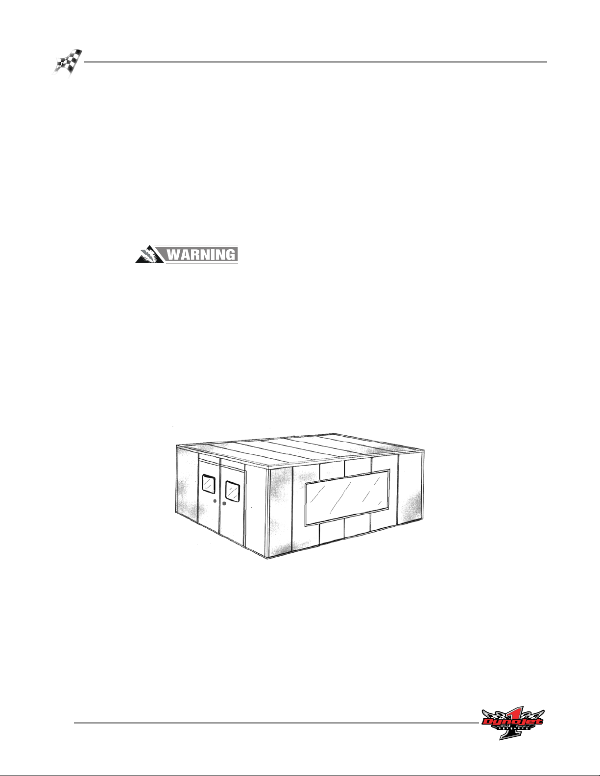
Industrial Noise Control, Inc.—Industrial Noise Control, Inc. offers a zinc-coated
steel room custom built to your specifications. This room meets all dyno room
requirements. The dyno room must be clean and dry with a comfortable room air
temperature above 32 degrees Fahrenheit (0 degrees Celsius), and have some system
of exhaust extraction. For more information on a dyno room, refer to your
Pre-Installation Guide For Model 200i, 250i, 200ip, and 250ip Motorcycle
Dynamometers (P/N 98129103).
Figure 1-1: Custom Dyno Room
1-4
Model 200i and 250i Motorcycle Dynamometer Installation Guide
Page 17

SPECIFICATIONS AND OPERATING REQUIREMENTS
Dynamometer Specifications and Requirements
DYNAMOMETER SPECIFICATIONS AND REQUIREMENTS
. . . . . . . . . . . . . . . . . . . . . . . . . . . . . . . . . . .
The following specifications and requirements will help you set up your dyno area
and verify you have the requirements to operate your dyno safely.
BATTERY REQUIREMENTS
Your 200i/250i dyno is designed to carry a group 24 deep-cycle discharge series
battery for operating the starter, power carriage, and optional wheel clamp. The
typical dimensions for this series of batteries are 27 cm long by 17 cm wide by 23 cm
tall (10.625-inches by 6.75-inches by 9.125-inches). The mounting is flexible so a
battery that has dimensions close to this will work satisfactorily. The built-in battery
cables are configured for top-post batteries. This battery is not included with your
dyno. You will need to provide this battery. For more information on installing the
battery, refer to “Installing the Battery” on page 2-10.
CHASSIS SPECIFICATIONS
description specifications
Length
with standard carriage allow 271.78 cm (107.00 inches)
with extended carriage allow 322.58 cm (127.00 inches)
Height
to top of dyno cover 45.97 cm (18.10 inches)
Width
model 200i 106.68 cm (42.00 inches)
model 250i 179.60 cm (70.71 inches)
Weight
model 200i dyno/crated dyno 725 kg (1600 pounds)/771 kg (1700 pounds)
model 250i dyno/crated dyno 1,077.28 kg (2,375 pounds)/1,133.98 kg (2,500 pounds)
Drum
diameter 45.72 cm (18.00 inches)
width 50.80 cm (20.00 inches)
Frame structural steel channel and angle
Maximum Speed 322 KPH (200 MPH)
Maximum Motorcycle Length (front of
front wheel to center of rear wheel)
standard carriage 213 cm (84.00 inches)
extended carriage 256.54 cm (101.00 inches)
Remote Switches remote software control
Version 5 Model 200i and 250i Motorcycle Dynamometer Installation Guide
1-5
Page 18
CHAPTER 1
Dynamometer Specifications and Requirements
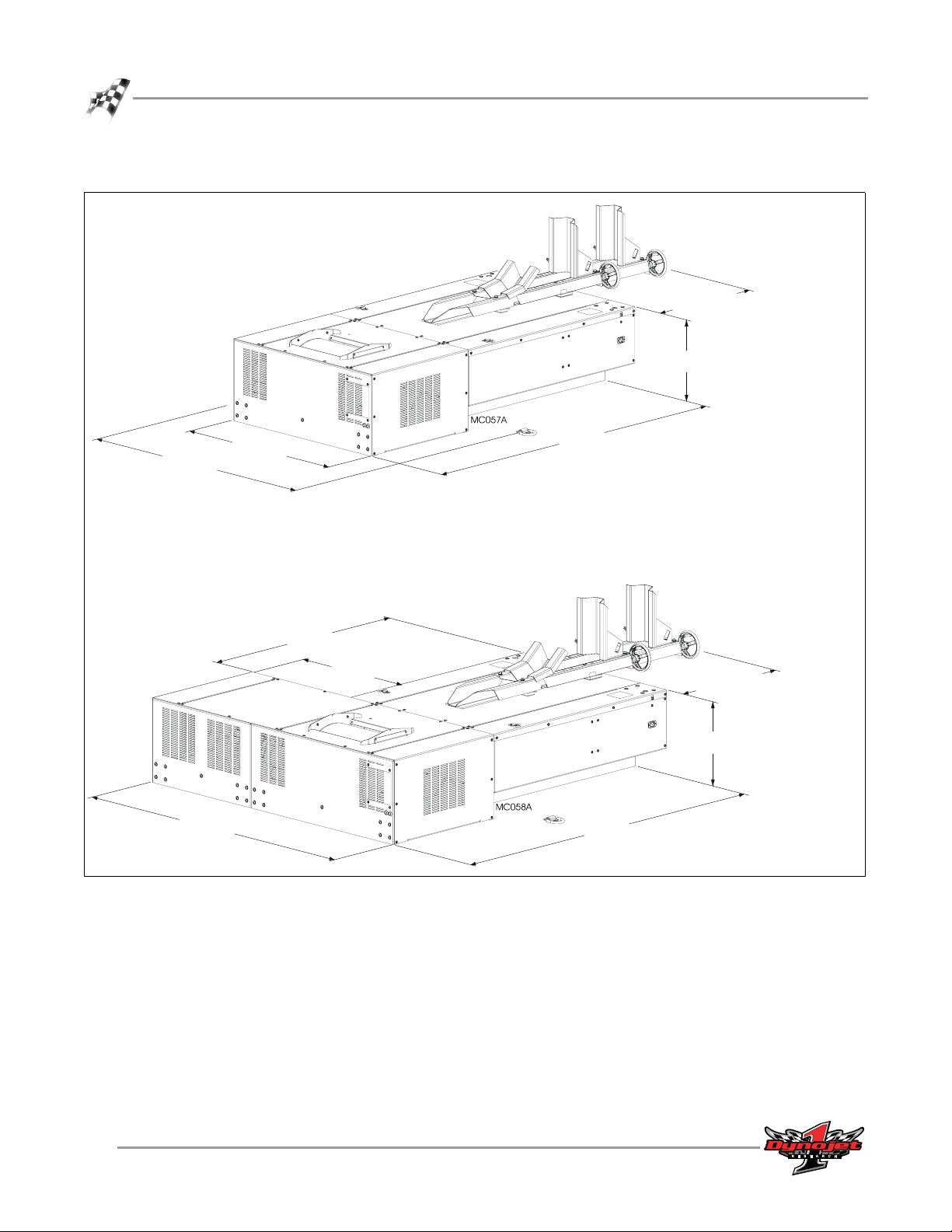
model 200i
carriage: allow 68.33 cm (26.9 in.)
extended carriage: allow
119.38 cm (47.0 in.)
45.97 cm (18.10 in.)
152.40 cm
(60.00 in.)
model 250i
179.60 cm
(70.71 in.)
106.68 cm
(42.00 in.)
127.74 cm
(50.29 in.)
72.92 cm
(28.71 in.)
202.77 cm
(79.83 in.)
carriage: allow 68.33 cm (26.9 in.)
extended carriage: allow
119.38 cm (47.0 in.)
45.97 cm (18.10 in.)
202.77 cm
(79.83 in.)
1-6
Model 200i and 250i Motorcycle Dynamometer Installation Guide
Figure 1-2: Model 200i and 250i Dimensions
Page 19

COMPRESSED AIR REQUIREMENTS
The following requirements are needed when the optional air brake is included.
• regulator set to 65 psi max (450 kilopascal)
•air dryer
• shut off valve
• gauge on the regulator
• 1/4-inch NPT pipe thread connector (to attach air to the dyno)
SPECIFICATIONS AND OPERATING REQUIREMENTS
Dynamometer Specifications and Requirements
COMPUTER SPECIFICATIONS
You will need to provide a computer system to run the WinPEP software. WinPEP 7
includes complete documentation in online Help. From the WinPEP 7 menu bar,
choose Help
name and password). Refer to the section on Computer Specifications in the WinPEP
documentation, P/N 98118103, for the specific computer system requirements.
!
WinPEP 7 Help or visit www.winpep.com (accessible with a valid user
ELECTRICAL REQUIREMENTS
The Model 200i/250i dynamometers require a 240V - 30a single-phase electrical
circuit for reliable and precise operation. No other loads should be plugged into this
circuit and this circuit should be independent of the lighting in the dyno room.
Before you plug in your dyno, you or your electrician must refer to Appendix B for
detailed information.
description specifications
Power Requirements 240v 30 amp single phase circuit
Frequency 50 or 60 Hz
Voltage
normal 240 VAC
min./max 215 VAC/245 VAC except Japan 195 VAC/245 VAC
Current 30 amps
Power Consumption 7200 watts
Power Cord P/N 76950401
length 3.048 m (10 ft.)
end twist-lock plug or three-pin IEC plug
wall receptacle (included with dyno) twist-lock four wire grounded 30A NEMA L14-30 or
three-pin IEC grounded 30A
Full Load Amperage (FLA) 30A
Version 5 Model 200i and 250i Motorcycle Dynamometer Installation Guide
1-7
Page 20
CHAPTER 1
Dynamometer Specifications and Requirements
ENVIRONMENTAL REQUIREMENTS
description specifications
Te mp e r at u r e
operating min./max 10°C/50°C (50°F/122°F)
storage min./max 0°C/60°C (32°F/140°F)
Humidity 0 to 95% non condensing
FORKLIFT REQUIREMENTS
You will need to provide equipment capable of lifting a minimum of 1,133.98 kg
(2,500 lbs.) to lift the dyno off the crate and into position in your dyno room. You will
also need a pair of straps capable of supporting 1,133.98 kg (2,500 lbs.) to attach to
the dyno. Dynojet recommends using single loop style straps.
GROUND HOOK REQUIREMENTS
You may wish to install additional ground hooks (included with your dyno) for
securing the motorcycle. The tie-down loops on the pit covers should work for most
motorcycles. If you are running motorcycles that require a different tie-down location,
mount the ground hooks accordingly.
Note: Tie-down straps MUST pull the motorcycle forward.
Using the ground hooks as a pattern, install the Red Head anchors using the hardware
included with the ground hook kit. Install the Red Head anchors according to the
instructions in Appendix A.
PHONE AND INTERNET ACCESS
Dynojet recommends you have a phone close to the dyno to call for assistance in an
emergency. You may also wish to contact Dynojet to troubleshoot your dyno.
Internet access on your computer is desirable for contacting Dynojet and
downloading new information and updates.
TIE-DOWN STRAPS
Dynojet recommends using motorcycle tie-down straps for securing the bike on the
dyno. You will need to provide the tie-down straps.
1-8
Model 200i and 250i Motorcycle Dynamometer Installation Guide
Page 21
SPECIFICATIONS AND OPERATING REQUIREMENTS
Model 200i Motorcycle Dynamometer
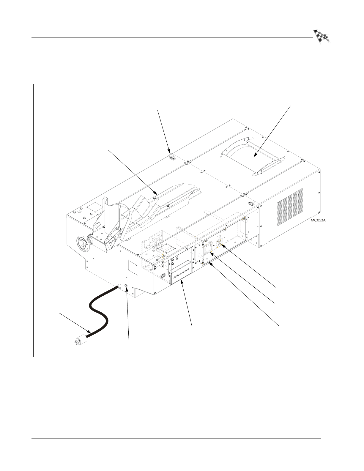
MODEL 200i MOTORCYCLE DYNAMOMETER
. . . . . . . . . . . . . . . . . . . . . . . . . . . . . . . . . . .
Tire Carriage
Tie-down Loop
used to secure the
motorcycle to dyno
Drum
precision balanced
and knurled
Breaker
Breakout Board
Power Cord
Dyno Electronics Enclosure
houses the dyno electronics and
Air Connector
Figure 1-3: Model 200i Basic Dyno
Version 5 Model 200i and 250i Motorcycle Dynamometer Installation Guide
power supply
Control Panel Interface
houses the Breakout board, main
power breaker, and battery disconnect
1-9
Page 22
CHAPTER 1
Model 250i Motorcycle Dynamometer
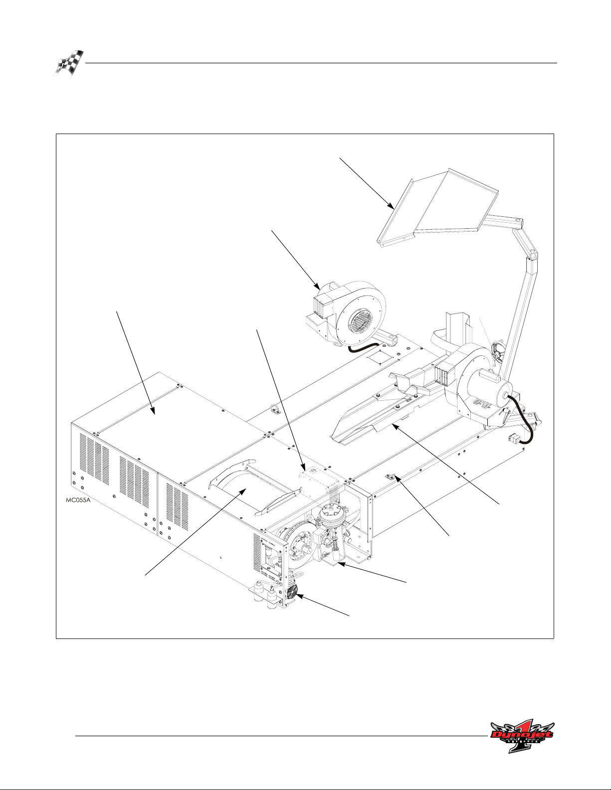
MODEL 250i MOTORCYCLE DYNAMOMETER
. . . . . . . . . . . . . . . . . . . . . . . . . . . . . . . . . . .
Power Carriage
not shown
Wheel Clamp
not shown
Control Panel
not shown
Eddy Current
Brake Module
Monitor Tray
supports the monitor,
keyboard, and mouse
High Pressure Blower
cools the bike’s engine
Theta Controller
controls the eddy
current brake
1-10
Model 200i and 250i Motorcycle Dynamometer Installation Guide
Drum
precision balanced
and knurled
Figure 1-4: Model 250i With Optional Accessories
Tire Carriage
Tie-do wn Lo op
used to secure the
motorcycle to dyno
Air Brake
Air Pump
Assembly
Page 23

C HAPTER
2
I
NSTALLATION
This chapter will walk you through unpacking and installing the dynamometer. To
ensure safety and accuracy in the procedures, perform the procedures as they are
described.
This chapter is divided into the following categories:
• Dyno Installation, page 2-2
• Battery, page 2-10
• Pickup Card, page 2-11
• Eddy Current Brake, page 2-12
• Support Arm and Monitor Tray, page 2-21
• Dyno Electronics, “Dyno Electronics” on page 2-23
• Routing Cables, page 2-25
• Tire Carriage Installation, page 2-34
• Drum Side and Top Covers, page 2-38
• Ramp Bracket, page 2-40
• Ground Hooks, page 2-43
• Zip Tube, page 2-44
Model 200i and 250i Motorcycle Dynamometer Installation Guide
2-1
Page 24
CHAPTER 2
Dyno Installation
DYNO INSTALLATION
. . . . . . . . . . . . . . . . . . . . . . . . . . . . . . . . . . .
The following directions describe how to unpack, and install your dyno. Follow the
directions in the order that they are presented.
UNPACKING AND INSPECTING YOUR DYNO
When you receive your dyno, examine the exterior of the shipping container for any
visible damage. If damage is detected at this stage, contact the shipper or Dynojet
before proceeding with unpacking.
Use the following steps to unload your dyno. You will need to provide equipment
capable of lifting a minimum of 1,133.98 kg (2,500 lbs.) to move the crated dyno into
position in your dyno room. Refer to “Dynamometer Specifications and
Requirements” on page 1-5 for more information.
1 Remove the crate braces and sides.
Note: At this point, you will want to inspect the exterior of the dyno for any
indications of damage. Report any damage immediately.
2 Remove the tire carriage. The tire carriage is fastened to the bottom of the crate.
3 Remove the support arm. The support arm is fastened to the bottom of the crate.
For more information on the support arm and monitor tray refer to page 2-21.
support arm
Figure 2-1: Remove the Tire Carriage and Support Arm from the Crate
2-2
Model 200i and 250i Motorcycle Dynamometer Installation Guide
tire carriage
Page 25
INSTALLATION
Dyno Installation
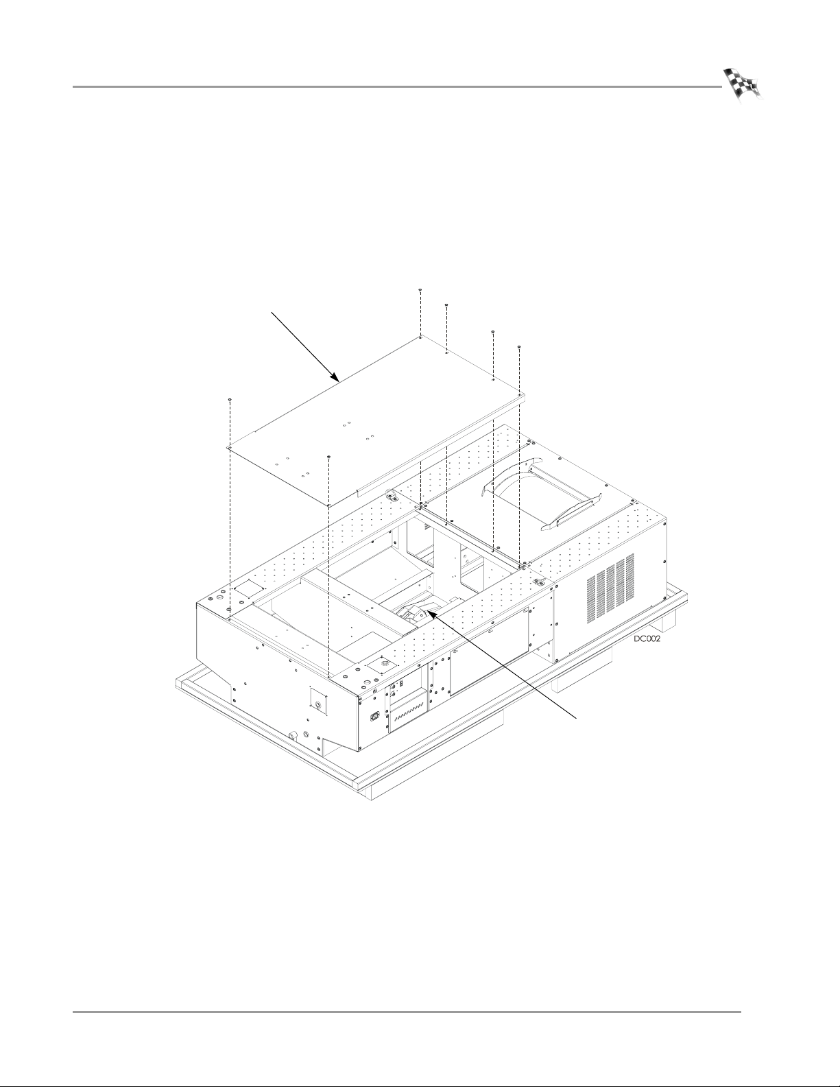
4 Remove the six 1/4-inch screws securing the center panel on the dyno and remove
the center panel.
Note: Dynojet recommends using a T30 Torx driver (Snap-On PFTx30E) to
remove the 1/4-inch screws. For dynos with serial numbers lower than 2030152,
Dynojet recommends using a hardened 5/32-inch hex driver (such as Snap-On
FA5E). A standard allen key may round off in the shallow screw head.
5 Remove the tire stop, tire lock, and hardware from the middle of the dyno.
center panel
tire stop and tire lock
in middle
Figure 2-2: Remove the Center Panel
Version 5 Model 200i and 250i Motorcycle Dynamometer Installation Guide
2-3
Page 26
CHAPTER 2
Dyno Installation
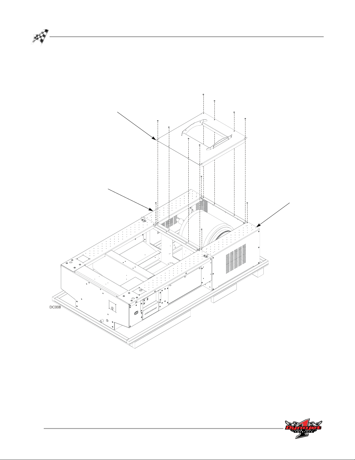
6 Remove the eight screws securing the top drum cover to the dyno and set aside.
Remove the drum cover and set aside.
7 Remove the two top screws securing each side drum cover to the dyno and set
aside.
top drum cover
side drum cover
side drum cover
Figure 2-3: Remove the Top Drum Cover
2-4
Model 200i and 250i Motorcycle Dynamometer Installation Guide
Page 27
INSTALLATION
Dyno Installation
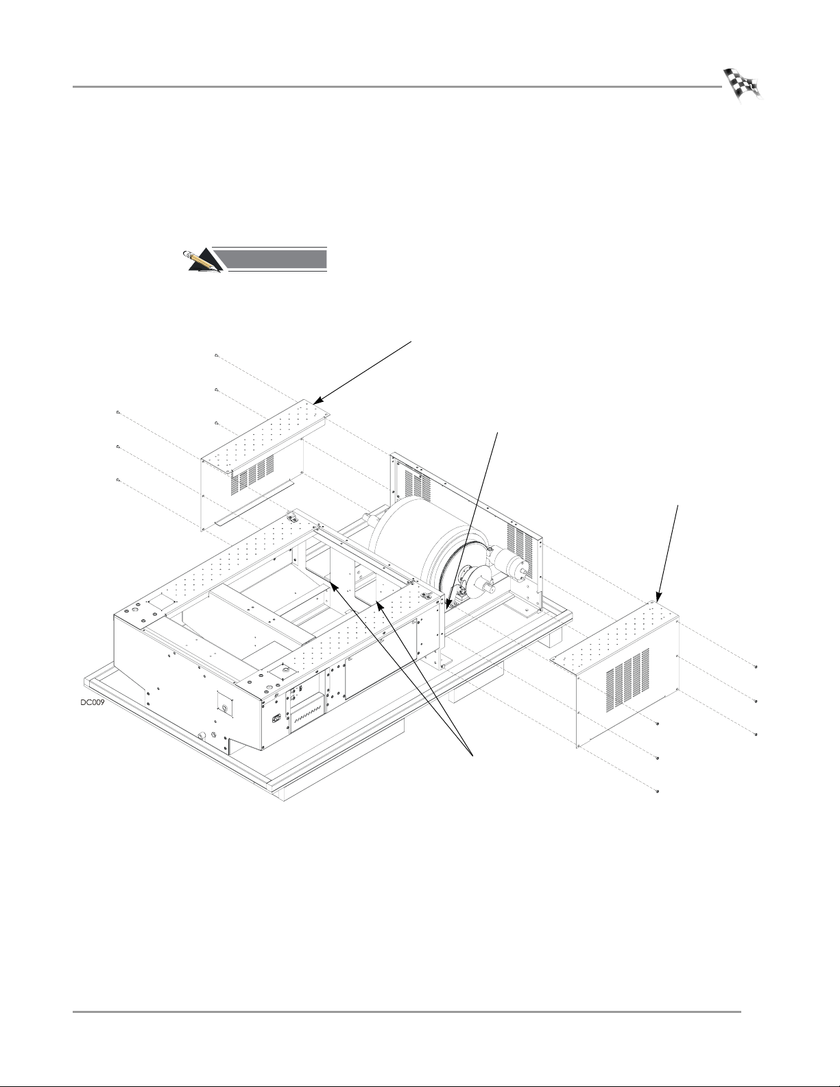
8 Remove the remaining six side screws securing each side drum cover to the dyno
and set aside. Remove the side drum covers and set aside.
Note: For future reference, note the three access holes in the drum bulkhead.
These access holes will be used to route cables when installing accessories once
the top cover is back on.
RECORD
Be sure you record the dynamometer number on the inside cover of this
manual.
#
side drum cover
dyno number stamped
on frame
side drum cover
access holes in drum
bulkhead (only two
visible from this view)
Figure 2-4: Remove the Side Drum Covers
Version 5 Model 200i and 250i Motorcycle Dynamometer Installation Guide
2-5
Page 28

CHAPTER 2
Dyno Installation
REMOVING THE DYNO FROM THE CRATE
You will need to provide equipment capable of lifting a minimum of 1,133.98 kg
(2,500 lbs.) to lift the dyno off the crate and into position in your dyno room. You will
also need a pair of straps capable of supporting 1,133.98 kg (2,500 lbs.) to attach to
the dyno. Dynojet recommends using a single loop style strap.
1 Remove the four lag bolts and washers securing the dyno to the crate base using a
9/16-inch socket, open or box end wrench.
2 The pickup card may be taped to the lifting eye. Remove the pickup card and set it
aside.
bolt and washer
lifting eye
bolt and washer not
visible from this view
Figure 2-5: Remove the Dyno from the Crate Base
2-6
Model 200i and 250i Motorcycle Dynamometer Installation Guide
bolt and washer
lifting eye
bolt and washer
Page 29
INSTALLATION
Dyno Installation
3 Route the single loop strap through the lifting eyes in front of the drum as shown
in Figure 2-6.
Note: The dyno should only be lifted using the lifting eyes. Verify no other part of
the dyno is interfering with the strap. Do not place the strap around the cable
routing bracket or any other part of the dyno.
lifting eye
cable routing
bracket
lifting eye
Figure 2-6: Loop Strap Placement
4 Carefully lift the dyno off the crate and move into position in your dyno room.
Note: While the dyno is supported by the forklift and before it is placed in your
dyno room, the power cable must be routed through the front of the dyno.
loop strap
Figure 2-7: Lift the Dyno off the Crate
Version 5 Model 200i and 250i Motorcycle Dynamometer Installation Guide
2-7
Page 30
CHAPTER 2
Dyno Installation
ROUTING THE POWER CABLE
1 Locate the power cable inside the dyno.
2 Slide the strain relief on the power cable through the opening in the dyno frame.
3 Tighten the jam nut.
4 Hand tighten the knurled nut.
opening in
dyno frame
strain relief around
power cord
Figure 2-8: Route the Power Cable
jam nut
inside dyno
cut away view from
inside dyno
knurled nut
outside dyno
2-8
Model 200i and 250i Motorcycle Dynamometer Installation Guide
Page 31

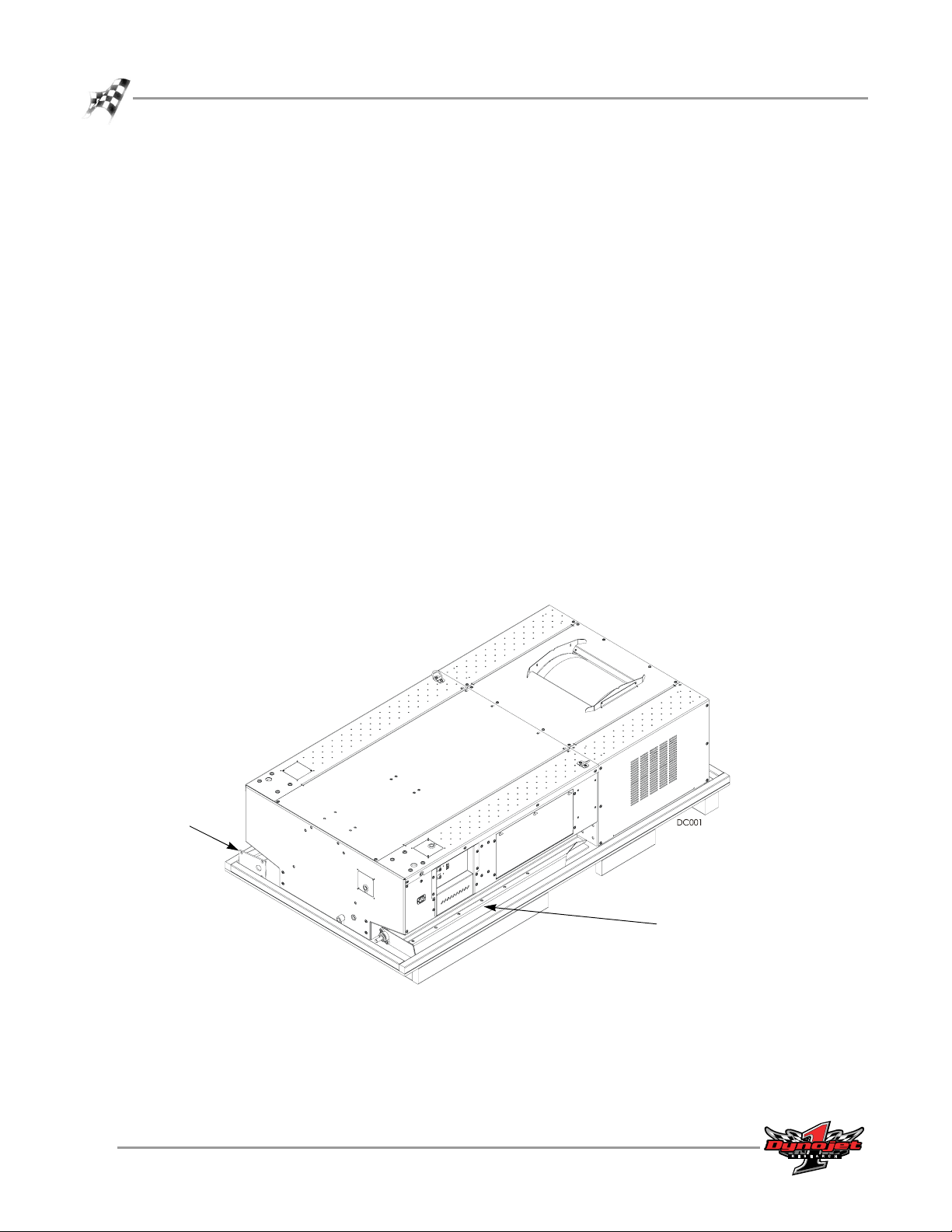
POSITIONING AND SECURING THE DYNO
1 Gently lower the dyno into position. Be sure the location you have chosen for
your dyno has enough room in front of the dyno for the maximum extension of
the carriage. Refer to “Dynamometer Specifications and Requirements” on page 15 for more information.
2 Secure the dyno to the floor in your dyno room.
Note: Skip this step if you will be installing the eddy current brake. Install the
eddy current brake first, and then secure the dyno and the eddy current brake to
the floor.
Dynojet recommends you secure your dyno to the floor in your dyno room using
concrete anchors. You will want to mark and drill the holes in your concrete
before adding any accessories or replacing the covers on your dyno.
2a Mark and drill holes.
2b Install the Red Head anchors according to the instructions in Appendix A.
MC118
INSTALLATION
Dyno Installation
mark and drill hole
mark and drill holes
hole not visible from
this view
Figure 2-9: Anchor Hole Placement
Version 5 Model 200i and 250i Motorcycle Dynamometer Installation Guide
2-9
Page 32

CHAPTER 2
Battery
BATTERY
. . . . . . . . . . . . . . . . . . . . . . . . . . . . . . . . . . .
The model 200i/250i dyno is designed to carry a group 24 deep-cycle discharge series
battery for operating the starter, optional power carriage, and optional wheel clamp.
The typical dimensions for this series of batteries are 27 cm long by 17 cm wide by 23
cm tall (10.625-inches by 6.75-inches by 9.125-inches). The mounting is flexible so a
battery that has dimensions close to this will work satisfactorily. The built-in battery
cables are configured for top-post batteries. This battery is not included with your
dyno. You will need to provide this battery.
Note: If you do not wish to use the wheel clamp and the power carriage or
operate the built-in starter then it is not necessary to install the battery.
INSTALLING THE BATTERY
There is danger of explosion if the battery is incorrectly connected or replaced.
Wear protective clothing, eye, and face protection when charging or handling
batteries. Refer to Warnings for more information.
1 Locate the red battery cable on the inside of the dyno.
2 Place the battery in the battery carrier on the inside of the dyno so the red cable
can reach the positive (+) post on the battery and the black battery cable can
reach the negative (-) post.
3 Secure the red battery cable to the positive (+) battery post.
4 Secure the black battery cable to the negative (-) battery post.
5 Secure the battery to the tray with the battery hold-down.
battery
Figure 2-10: Install the Battery
2-10
Model 200i and 250i Motorcycle Dynamometer Installation Guide
Page 33

PICKUP CARD
. . . . . . . . . . . . . . . . . . . . . . . . . . . . . . . . . . .
The pickup card is an electronic circuit board that accurately senses each drum
revolution.
1 Locate the pickup card bracket on the right side of the dyno just ahead of the
drum.
2 Install the pickup card to the bracket using two No. 8 screws. Do not tighten, the
card must be aligned first.
Note: If your dyno is equipped with an air brake, you will need to attach
compressed air and power to your dyno before you can turn the drum. Refer to
Figure 3-6 on page 3-7 for more information on attaching compressed air to your
dyno.
3 Align the optical pickup card with the tab on the dyno drum axle. Be sure the tab
passes freely through the optical pickup. You may need to loosen the bracket to
help with alignment.
4 Once aligned, tighten the screws to secure the pickup card in place.
INSTALLATION
Pickup Card
The optical pickup is very delicate. Be careful not to damage the optical pickup
during alignment.
tab on dyno
optical pickup
pickup card
top view of pickup card, optical
pickup, and tab on dyno
pickup card
bracket
tab on dyno
pickup card
Figure 2-11: Install the Pickup Card
Version 5 Model 200i and 250i Motorcycle Dynamometer Installation Guide
2-11
Page 34

CHAPTER 2
Eddy Current Brake
EDDY CURRENT BRAKE
. . . . . . . . . . . . . . . . . . . . . . . . . . . . . . . . . . .
The eddy current brake is an optional accessory. This section will walk you through
removing the eddy current brake from the crate, and attaching the brake to your
dyno. If you did not purchase the eddy current brake, skip this section and continue
with “Installing the Support Arm and Tray” on page 2-21.
You will need to provide equipment capable of lifting the eddy current brake off the
crate and into position in your dyno room. You will also need a pair of straps. Dynojet
recommends using continuous nylon loop style straps.
To prevent possible injury, verify all power cords are unplugged.
PARTS LIST
The following table lists all of the parts included in the Eddy Current Brake
(P/N 63223700) Installation kit. Check your kit against the parts listed to make sure
you have received all of the parts. If any part is missing, contact Dynojet Technical
Support.
part number description quantity
21227107 Retarder Connector Plate (already installed) 2
21629403 Bar, Load Cell 1
36582034 Screw, 3/8”-16 x 1 1/4”, BH-FLNG 8
37620622 Woodruff Key, 3/8” x 1 3/8” 1
49950030 Temperature Sensor 1
61228400 Hood, Top, Retarder Module 1
63223700 Retarder Module 1
66411003 Theta-2 Controller 240V 1
2-12
Model 200i and 250i Motorcycle Dynamometer Installation Guide
Page 35

UNPACKING THE EDDY CURRENT BRAKE
1 Remove the sides of the crate.
2 Remove the four screws securing the top cover and set aside. Remove the cover
and set aside.
3 Remove the hardware box and theta controller from the crate and verify the
hardware box contents using the parts list.
For more information on mounting the theta controller refer to page 2-20.
INSTALLATION
Eddy Current Brake
RECORD
Be sure you record the eddy current brake number on the inside cover of this
manual.
top cover
#
eddy current brake number
Figure 2-12: Remove the Covers
Version 5 Model 200i and 250i Motorcycle Dynamometer Installation Guide
2-13
Page 36

CHAPTER 2
Eddy Current Brake
4 Remove the four bolts securing the brake to the crate.
5 Determine if the brake is to be mounted on the left or right side of your dyno.
Make the following adjustments to the eddy current brake only if you want
to mount the brake on the opposite side of the dyno that it is currently set
up for.
5a Move the coupler and key to the other side of the brake.
• To remove the key, use a punch and a hammer to apply pressure in the
direction of the arrows shown in Figure 2-14.
5b Move the retarder connector plates to the other side of the brake.
5c Move the temperature sensor to the other side of the brake.
front of dyno
retarder
connector plates
eddy current brake set up for left side installation
Figure 2-13: Identifying Left or Right Side Brake Set Up
shaft
connector plates
apply force using
hammer and punch
temperature
sensor
coupler
retarder
key
eddy current brake set up for right side installation
apply force using
hammer and punch
2-14
Model 200i and 250i Motorcycle Dynamometer Installation Guide
Figure 2-14: Remove the Key
Page 37

INSTALLATION
Eddy Current Brake
6 Remove the side drum cover, if not already removed, from the dyno.
Refer to Figure 2-4 on page 2-5.
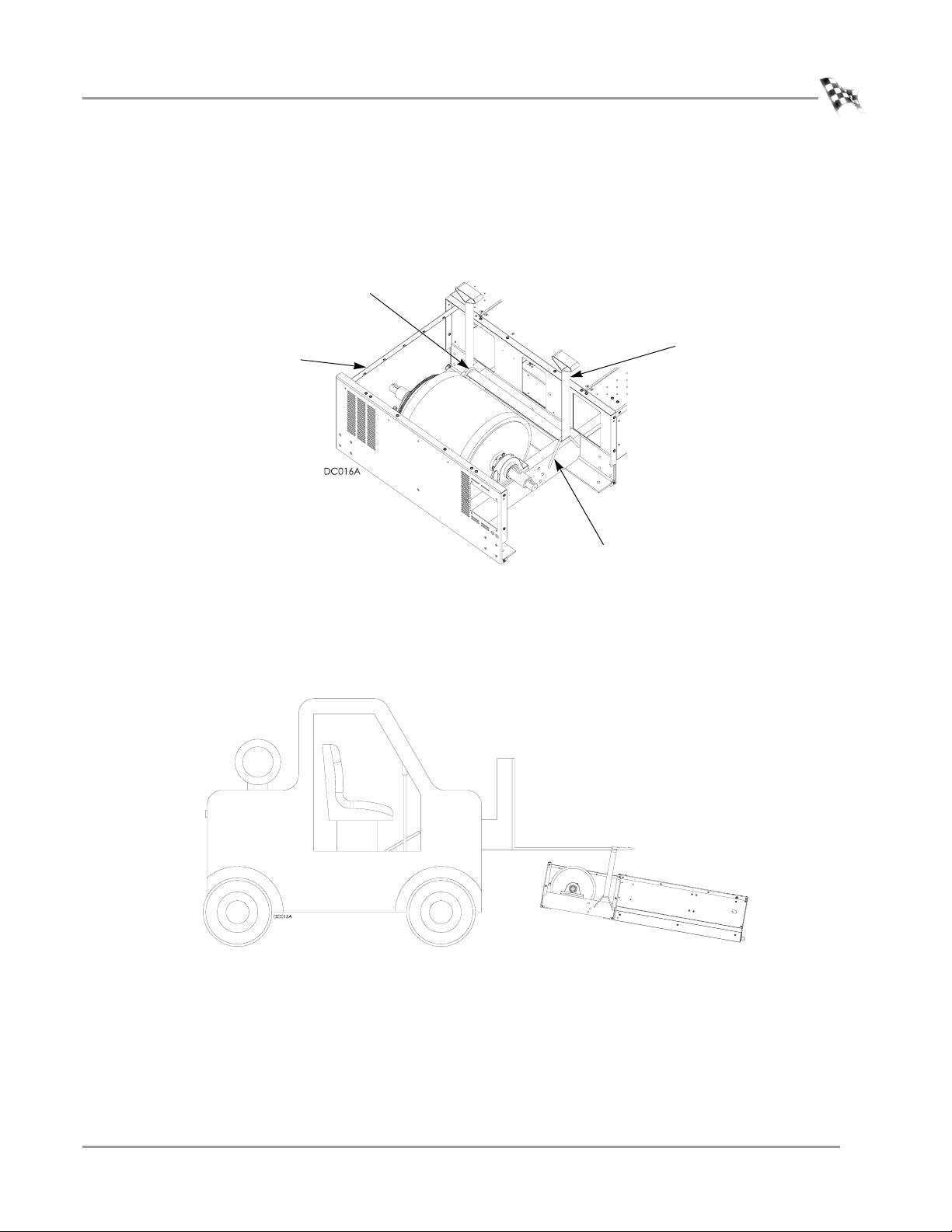
7 Place the nylon loop strap through the lifting eyes on either side of the brake.
8 Using a forklift, lift the eddy current brake from the crate and place the brake near
the dyno making sure the panels on the brake and dyno are parallel.
9 Remove the eight bolts, washers, and nuts from the dyno frame where the
connector plates will attach.
10 Remove the starter brace, if present.
Note: Only remove the starter brace when installing the eddy current brake on
the left (starter) side of the dyno.
10a Remove the three bolts, washers, and nuts securing the starter brace and set
aside.
10b Remove the starter brace and set aside.
starter brace
EB141
lifting eye
remove bolts, washers, and
nuts from dyno frame
Figure 2-15: Move the Brake Next to the Dyno
line up panels
lifting eye
Version 5 Model 200i and 250i Motorcycle Dynamometer Installation Guide
2-15
Page 38

CHAPTER 2
Eddy Current Brake
INSTALLING THE EDDY CURRENT BRAKE
The eddy current brake comes with the coupler already installed on the brake shaft.
The eddy current brake can be installed on either side of your dyno. The air brake is
located on the right side of the dyno. It is not necessary to remove the air brake
regardless of which side of the dyno you are installing the eddy current brake: right or
left.
Note: Safety requirements of your local country may require that both brakes are
installed. Be sure to follow the safety requirements specific to your country.
1 Insert the key into the keyway.
2 Use a c-clamp to press the key in, if necessary.
key
key way on dyno shaft
EB142
retarder connector plate
2-16
Model 200i and 250i Motorcycle Dynamometer Installation Guide
Figure 2-16: Install the Key
Page 39

INSTALLATION
Eddy Current Brake
3 Keeping the panels parallel, slide the eddy current brake towards the dyno. Slide
the coupler over the key on the dyno shaft. You will need to support the coupler
as you slide it onto the dyno shaft.
4 Continue sliding the eddy current brake towards the dyno until the covers on the
brake and dyno are flush.
5 Secure the retarder connector plate to the dyno frame using the four bolts,
washers, and nuts removed earlier. There is a retarder connector plate on either
side of the brake. Refer to Figure 2-17.
Note: Do not tighten the bolts.
6 Verify the covers on the brake and the dyno line up. These covers must be flush
and parallel. If these covers are not flush, place shims between the floor and the
eddy current brake or the dyno until they are flush.
7 Once aligned, tighten all retarder connector plate bolts and nuts.
8 Secure the starter brace to the starter using the washer and nut removed earlier.
starter brace
retarder connector plate
EB143
three bolts not visible
from this view
Figure 2-17: Secure the Retarder Connector Plate and Starter Brace
Version 5 Model 200i and 250i Motorcycle Dynamometer Installation Guide
2-17
Page 40

CHAPTER 2
Eddy Current Brake
9 Secure the side panels on the eddy current brake to the panels on the dyno using
not visible from
this view
a 1/4-20 bolt. Do this on each side.
EB144
Figure 2-18: Secure the Side Panels to the Dyno
10 Replace the existing set screws on the coupler with the thread-lock set screws
provided.
11 Tighten the coupler set screws.
brake shaft
set screw
dyno shaft
Figure 2-19: Tighten the Set Screws
2-18
Model 200i and 250i Motorcycle Dynamometer Installation Guide
Page 41

SECURING THE DRUM AND BRAKE MODULE TO THE FLOOR
Dynojet recommends you anchor the eddy current brake, along with the dyno, to the
floor in your dyno room using concrete anchors. You will want to drill the holes and
secure the dyno before placing the covers on your dyno.
1 Mark and drill the holes for the Red Head anchors.
2 Install the Red Head anchors according to the instructions in Appendix A.
3 Secure the eddy current brake to the ground using the same holes used to secure
the brake to the crate. Secure the dyno to the ground using the holes you drilled
previously.
MC122
INSTALLATION
Eddy Current Brake
mark and drill
holes for red head
anchors
mark and drill
holes for red
head anchors
mark and drill
holes for red
head anchors
Figure 2-20: Secure the Dyno and Brake Module to Floor
Version 5 Model 200i and 250i Motorcycle Dynamometer Installation Guide
2-19
Page 42

CHAPTER 2
Eddy Current Brake
INSTALLING THE THETA CONTROLLER
The theta controller is the interface between the eddy current brake and the dyno
electronics. You will only install the theta controller if you ordered an eddy current
brake. You will route the cables to it later. The theta controller is shipped in the eddy
current brake crate.
1 Verify the theta controller dip switch settings. Refer to Appendix C for more
information.
2 Secure the theta controller to the drum module bulkhead using four
8-32 x 3/8-inch screws as shown in Figure 2-21.
four 8-32 x 3/8"
screws
theta controller
EB146
Figure 2-21: Installing the Theta Controller
2-20
Model 200i and 250i Motorcycle Dynamometer Installation Guide
Page 43

INSTALLATION
Support Arm and Monitor Tray
SUPPORT ARM AND MONITOR TRAY
. . . . . . . . . . . . . . . . . . . . . . . . . . . . . . . . . . .
This articulated arm and platform supports the monitor, keyboard, and mouse in a
convenient position for operation while seated on the motorcycle. The support arm
can be mounted on either side of the dynamometer.
PARTS LIST
The following table lists all of the parts included in the Monitor Stand Installation kit.
Check your kit against the parts listed to make sure you have received all of the parts.
If any part is missing, contact Dynojet Technical Support.
part number description quantity
21229300 Monitor Arm Tray 1
32391064 Bushing, 1" x 2", 10 Gauge, Stl 3
35521420 Plastic Cap, 1.75" x 1/2", Black 4
36701100 Nut, 1/2-13, Hex 2
36801253 Screw, 1/2-13 x 1.5", Sh-Cap 2
36932100 Washer, 3/8", Splitlock, Stl 1
36942100 Washer, 1/2", Splitlock, Stl 2
36943100 Washer, 1/2", Flat, Stl 4
61329100 Monitor Arm 2
INSTALLING THE SUPPORT ARM AND TRAY
The support arm and monitor tray may be installed on either side of your dyno.
1 Remove the four 3/8-16 x 1/2-inch button-head flange screws from the dyno
where you plan to install the support arm.
2 Using an allen wrench, secure the support arm to the dyno frame with four
3/8-16 x 1/2-inch button-head flange screws you removed earlier.
3 Place a poly washer around the pin of the first arm and insert the arm into the
support arm.
4 Place a poly washer around the pin of the second arm and insert the arm into the
first arm.
5 Place a poly washer around the pin of the tray and insert the tray into the second
arm.
6 Insert a plastic cap in both ends of each arm.
7 Check for clearance between the monitor arm and motorcycle, walls, ceiling, etc.
Note: Dynojet does not recommend placing the computer CPU on the
monitor/keyboard tray since vibration can cause damage to the computer.
Version 5 Model 200i and 250i Motorcycle Dynamometer Installation Guide
2-21
Page 44

CHAPTER 2
Support Arm and Monitor Tray
poly washer
second arm
poly washer
first arm
poly washer
monitor tray
support arm
MA017
Figure 2-22: Install the Support Arm and Monitor Tray
2-22
Model 200i and 250i Motorcycle Dynamometer Installation Guide
Page 45

DYNO ELECTRONICS
. . . . . . . . . . . . . . . . . . . . . . . . . . . . . . . . . . .
The standard dyno electronics package is comprised of four interconnected modules:
Atmospheric Sensing Module, RPM Module, Dynamometer Input/Output Module, and
the CPU Module. For more information about their function refer to your WinPEP 7
User Guide (P/N 98128104).
9-pin hand
system expansion
connector
held pendant
25-pin socket
RPM inductive
pickup socket
INSTALLATION
Dyno Electronics
atmospheric
sensing module
RPM module
input/output module
Figure 2-23: The Dyno Electronics
CPU module
power
9-pin RS-232 socket
3-pin power plug
Version 5 Model 200i and 250i Motorcycle Dynamometer Installation Guide
2-23
Page 46

CHAPTER 2
Dyno Electronics
The standard dyno electronics is located inside the dyno electronics enclosure which
is already mounted to the dyno chassis as shown in Figure 2-24. Cables which you will
route in the next steps are prewired to the dyno electronics or to the CPI. You will
connect the free ends of the cables to the appropriate devices.
CPI
cables are pre-attached
to the dyno electronics
located inside the
dyno electronics
enclosure
MC120
dyno electronics
enclosure
dyno electronics
enclosure
Figure 2-24: Location of Dyno Electronics
2-24
Model 200i and 250i Motorcycle Dynamometer Installation Guide
Page 47

INSTALLATION
ROUTING CABLES
. . . . . . . . . . . . . . . . . . . . . . . . . . . . . . . . . . .
For the following instructions, the support arm and control panel are shown
mounted on the right side of the dyno.
ROUTING THE PENDANT, RS232 COMPUTER CABLE, AND CONTROL PANEL CABLE
1 Remove the two screws securing the cable pass through cover (shown in
Figure 2-25) closest to the monitor support and set it aside. The cables you will
route will be coiled inside the chassis.
2 Route the pendant cable, 9-pin RS232 computer cable (P/N 42967090), and the
15-pin control panel cable, labelled Button Panel P1, from the dyno electronics
CPU Module through the cable pass through cover on the side closest to where
you installed your monitor arm.
3 Place a split snap bushing around the pendant cable and the RS232 cable and
secure them through one hole in the cable pass through cover.
4 Place a split snap bushing around the control panel cable and secure it in the
other hole on the cable pass through cover. The bushing should be around the
cable protective wrap.
5 Secure the cable pass through cover to the dyno with the two screws removed
earlier.
Routing Cables
pendant
route 9-pin RS232 cable
to your computer
15-pin control panel cable
labelled Button Panel P1
monitor support
cable pass through
cover
CP026
Figure 2-25: Route the Control Panel and Pendant Cables
Version 5 Model 200i and 250i Motorcycle Dynamometer Installation Guide
2-25
Page 48

CHAPTER 2
Routing Cables
6 Locate the control panel and ready it to connect the control panel cable. The
control panel ships in a separate container inside the dyno.
6a Remove the two nuts from the top of the cover and set aside.
6b Remove the screw on the top of the cover and set aside.
6c Remove the screw on the side of the cover and set aside.
6d Remove the four screws on the back of the cover and set aside.
6e Remove the control panel rear cover and set aside.
top screw
CP025
top nuts
back cover screws
Figure 2-26: Locate the Control Panel and Remove the Back Cover
rear screws
side screw
2-26
Model 200i and 250i Motorcycle Dynamometer Installation Guide
Page 49

INSTALLATION
Routing Cables
7 Route the control panel cable through the access hole on the side of the control
panel box and through the cable tie.
8 Attach the control panel cable to the Button board.
control panel cable with
cable harness wrap
Figure 2-27: Attach the Control Panel Cable to the Button Board
9 Secure the rear cover to the control panel.
9a Replace the four screws on the back of the cover removed earlier.
9b Replace the screw on the top of the cover removed earlier.
9c Replace the screw on the side of the cover removed earlier.
9d Replace the two nuts on the top of the cover removed earlier.
access hole
cable tie
button board
Figure 2-28: Replace the Control Panel Rear Cover
Version 5 Model 200i and 250i Motorcycle Dynamometer Installation Guide
2-27
Page 50

CHAPTER 2
Routing Cables
10 Secure the control panel to the monitor tray using two 8-32-inch screws.
CP023
install control panel
spindle if you did not
purchase the monitor
tray
Note: If you did not order a monitor tray, install the control panel spindle to the
back of your control panel using four 8-32 screws. Once installed, place the
spindle on the control panel into the support arm where the monitor tray is
shown in Figure 2-29.
control panel
CP027
Figure 2-29: Install the Control Panel
2-28
Model 200i and 250i Motorcycle Dynamometer Installation Guide
Page 51

INSTALLATION
Routing Cables
11 Place the pendant in the slot provided on the control panel and route the cable
bundle along the support arms with service loops to allow movement.
12 If you plan to route your cables through a zip tube refer to “Zip Tube” on page 2-
44 and skip the following steps.
13 Attach the cable bundle with the cable clamps that are provided using 8-32-inch
screws. Adjust the service loops to allow for easy movement of the monitor arms
without pulling on the cables.
You may want to route the RS232 connector to your computer part way up the
support arm along with the control panel and pendant cables depending on
where you your computer is located.
pendant
control panel
cable
CP028
cable clamps
Figure 2-30: Secure the Control Panel Cable to the Support Arm
Version 5 Model 200i and 250i Motorcycle Dynamometer Installation Guide
2-29
Page 52

CHAPTER 2
Routing Cables
ROUTING THE EDDY CURRENT BRAKE CABLES
With the center panel off, now is a good time to connect and route the theta
controller cables. You will only have a theta controller if you installed the optional
eddy current brake accessory, see Figure 2-21 on page 2-20.
1 Attach the input power cable (P/N 66952004) to the top of the theta controller.
2 Route the eddy current brake cable (P/N 66952003) from the eddy current brake
to the bottom of the theta controller.
3 Route the control cable from the theta controller out of the side of the dyno
chassis to the Breakout board through the hole in the CPI shown in Figure 2-31.
4 Route the temperature sensor cable from the eddy current brake through the air
hole in the drum bulkhead, through the opening on the side of the CPI, and over
to the Breakout board.
Note: For more information on wiring the Breakout board refer to page 2-31.
air hole in drum
input power
bulkhead
EB148
theta controller
control cable
breakout board
Figure 2-31: Route the Eddy Current Brake Cables
eddy current brake cable
temperature
sensor cable
2-30
Model 200i and 250i Motorcycle Dynamometer Installation Guide
Page 53

WIRING THE BREAKOUT BOARD
1 Attach the temperature sensor cable to the Breakout board. The temperature
sensor cable has five wires which connect to the wiring block labeled TEMP. This
cable was routed to the Breakout board on page 2-30.
• Green wire connects to G1 • White wire connects to W1
• Black wire connects to B1 • Red wire connects to R1
• Ground (shield) wire connects to S1
INSTALLATION
Routing Cables
2 Attach the theta controller cable to the Breakout board, if it is not already
connected. The theta controller cable has five wires which connect to the wiring
block labeled LOAD CONTROL.
• Black wire connects to V- • Red wire connects to V+
• White wire connects to O+ • Green wire connects to O-
• Ground (shield) wire connects to SH
3 Attach the pickup; card cable to the Breakout board. The pickup card cable has
four wires which connect to the wiring block labeled DRUM 1.
• Red wire connects to R1 • Black wire connects to B1
• White wire connects to W1 • Ground (shield) wire connects to S1
4 Verify jumpers J1 and J2 are set either for the eddy current brake and air brake or
for the air brake only as shown in Figure 2-32.
If you have an eddy current brake and air brake, the air brake will only be
activated when the dyno electronics power is turned off or the optional door
interlock is installed and activated.
5 Close the power distribution enclosure door.
temp
eddy current brake only or
eddy current brake and air
pickup card
J2 J1
brake with control panel
J1J2
load control
Figure 2-32: Wire the Breakout Board
Version 5 Model 200i and 250i Motorcycle Dynamometer Installation Guide
air brake
only
2-31
Page 54

CHAPTER 2
Routing Cables
ROUTING THE POWER CARRIAGE AND WHEEL CLAMP CABLES
The power carriage and wheel clamp are optional accessories. These cables will only
be used if you ordered the accessories.
For installation instructions refer to “Power Carriage” on page 3-42 and “Wheel
Clamp” on page 3-47 for more information.
1 Remove the two screws securing the cable pass through cover on the front of the
dyno and set aside.
2 Locate the cables bundled inside the dyno.
3 Route the power carriage and wheel clamp cables through the opening in the
front of the dyno.
route cables
through
cable pass through
cover
Figure 2-33: Remove the Cable Pass Through Cover
2-32
Model 200i and 250i Motorcycle Dynamometer Installation Guide
Page 55

INSTALLATION
Routing Cables
4 Place a split snap bushing around the wheel clamp cable and secure into place in
one hole on the cable pass through cover.
5 Place a split snap bushing around the power carriage cable and secure into place
in the other hole on the cable pass through cover.
6 Secure the cable pass through cover to the dyno with the two screws removed
earlier.
cable pass through
cover
WC012
3-pin power carriage cable
Figure 2-34: Routing Wheel Clamp and Power Carriage Cables
2-pin wheel clamp cable
Version 5 Model 200i and 250i Motorcycle Dynamometer Installation Guide
2-33
Page 56

CHAPTER 2
Tire Carriage Installation
TIRE CARRIAGE INSTALLATION
. . . . . . . . . . . . . . . . . . . . . . . . . . . . . . . . . . .
Be sure the location you have chosen for your dyno has enough room in front of the
dyno for the maximum extension of the carriage. Refer to “Dynamometer
Specifications and Requirements” on page 1-5 for more information. If you ordered
the extended wheel carriage accessory, refer to “Installing the Extended Carriage
Support Bracket” on page 3-31 and install it at this time.
The tire carriage is fastened to the bottom of the crate next to the dyno. Refer to
step 2 on page 2-2 for instructions on removing the tire carriage from the crate.
If you do not have the standard tire carriage with the bearing bracket, refer to
Appendix D for instructions on installing the standard tire carriage—discontinued.
Note: Before replacing the center panel and installing the tire carriage install the
air hose, the EEC Kit, the door safety switch, and any additional accessories you
may have ordered. Refer to the appropriate sections of this manual for installation
instructions.
1 Replace the center panel using the six 1/4-inch screws you removed. See Figure 2-
2 on page 2-3.
2 Install the three carriage clamps and shims using two 5/16-inch bolts and washers
each.
3 Install the nut block and shim using two 5/16-inch bolts and washers.
carriage clamp
nut block
shim
shim
DC030
Figure 2-35: Install the Carriage Clamps and Nut Block
2-34
Model 200i and 250i Motorcycle Dynamometer Installation Guide
Page 57

INSTALLATION
Tire Carriage Installation
4 Remove the four 1/4 x 20-inch button-head screws securing the bearing bracket.
5 Remove the bearing bracket and the carriage screw.
carriage
screw
Figure 2-36: Remove the Bearing Bracket and Carriage Screw
screw
bearing
bracket
Version 5 Model 200i and 250i Motorcycle Dynamometer Installation Guide
2-35
Page 58

CHAPTER 2
Tire Carriage Installation
6 Starting from the back of the dyno, slide the carriage under the carriage clamps.
7 Slide the carriage screw and the bearing bracket toward the nut block until the
carriage screw is touching the nut block.
8 Slide the hand crank onto the end of the carriage screw.
9 Secure the hand crank to the screw shaft by tightening the set screw using a
5/32-inch allen wrench.
10 Using the hand crank, screw the carriage through the nut block and into the
screw support bracket.
11 Secure the bearing bracket to the carriage using four 1/4-20 x 1/2-inch
button-head flange bolts removed earlier.
Note: If you ordered the power carriage accessory, refer to “Power Carriage” on
page 3-42 for installation instructions.
carriage
nut block
hand crank
DC031
carriage screw
bearing bracket
Figure 2-37: Install the Tire Carriage and Secure the Hand Crank
2-36
Model 200i and 250i Motorcycle Dynamometer Installation Guide
Page 59

tire stop
INSTALLATION
Tire Carriage Installation
12 Secure the tire stop to the carriage using four 3/8-16 x 1/2-inch button-head flange
bolts.
Note: If you purchased the wheel clamp accessory, refer to “Wheel Clamp” on
page 3-47 for installation instructions.
13 Secure the tire lock to the carriage using four 3/8-16 x 1/2-inch button-head flange
bolts.
tire lock
DC032
Figure 2-38: Install the Tire Stop and Tire Lock
Version 5 Model 200i and 250i Motorcycle Dynamometer Installation Guide
2-37
Page 60

CHAPTER 2
Drum Side and Top Covers
DRUM SIDE AND TOP COVERS
. . . . . . . . . . . . . . . . . . . . . . . . . . . . . . . . . . .
Before replacing the covers, be sure to install the battery, pickup card, eddy
current brake, and any accessories you may have purchased with your dyno.
Refer to Chapter 3 for accessory installation instructions.
1 Secure each side drum cover to the dyno using six of the screws you removed
earlier.
side drum cover
side drum cover
Figure 2-39: Replace the Side Drum Covers
2-38
Model 200i and 250i Motorcycle Dynamometer Installation Guide
Page 61

INSTALLATION
Drum Side and Top Covers
2 Secure the top of the side drum covers with the screws you removed earlier.
3 Refer to Appendix D and install and adjust the finger guards if they are required in
your location.
4 Secure the top drum cover to the dyno using the eight screws removed earlier.
top drum cover
MC047
Figure 2-40: Replace the Top Drum Cover
Version 5 Model 200i and 250i Motorcycle Dynamometer Installation Guide
2-39
Page 62

CHAPTER 2
Ramp Bracket
RAMP BRACKET
. . . . . . . . . . . . . . . . . . . . . . . . . . . . . . . . . . .
The ramp bracket allows you to attach your own ramp to the dyno. You will need to
modify your ramp to secure it to the ramp bracket.
1 With the ramp upside down, center the ramp bracket under the lip at the top of
the ramp.
2 Using the larger holes on the bracket, mark and drill two 3/8-inch holes in the
ramp.
ramp lip
ramp bracket
24 inches
Figure 2-41: Mark and Drill Ramp Bracket Holes
2-40
Model 200i and 250i Motorcycle Dynamometer Installation Guide
Page 63

INSTALLATION
Ramp Bracket
3 Insert the 3/8-inch bolts from the top of the ramp and secure using 3/8-inch
washers and nuts.
Figure 2-42: Secure the Bolts to the Ramp
4 Remove the four 1/4-inch bolts from the rear of the drum cover.
5 Secure the ramp bracket to the rear drum cover using the bolts you just removed.
Figure 2-43: Secure the Bracket to the Drum Cover
Version 5 Model 200i and 250i Motorcycle Dynamometer Installation Guide
2-41
Page 64

CHAPTER 2
Ramp Bracket
6 Place the ramp on the ramp bracket slipping the bolts on the ramp through the
large holes on the ramp bracket.
Figure 2-44: Place the Ramp on the Dyno
2-42
Model 200i and 250i Motorcycle Dynamometer Installation Guide
Page 65

GROUND HOOKS
. . . . . . . . . . . . . . . . . . . . . . . . . . . . . . . . . . .
You may wish to install additional ground hooks (included with your dyno) for
securing the motorcycle. Use the following instructions as a guide in placing your
ground hooks.
1 Locate each ground hook approximately 96.5 cm (38 inches) from the front of the
dyno and approximately 20 cm (8 inches) from the side of the dyno
(approximately 152.40 cm, 60 inches, apart).
2 Using the ground hooks as a pattern, install the Red Head anchors using the
hardware included with the ground hook kit. Install the Red Head anchors
according to the instructions in Appendix A.
approx. 152.40 cm (60 in.)
INSTALLATION
Ground Hooks
approx.
20 cm
(8 in.)
approx. 96.5 cm (38 in.)
Figure 2-45: Ground Hooks
Version 5 Model 200i and 250i Motorcycle Dynamometer Installation Guide
2-43
Page 66

CHAPTER 2
Zip Tube
ZIP TUBE
. . . . . . . . . . . . . . . . . . . . . . . . . . . . . . . . . . .
The zip tube encases the multiple cables running to the control panel. You will need
to use the cable wrap tool (P/N 16510001) to insert the cables into the zip tube.
1 Rotate the cable holder to the open position.
2 Insert the cable(s) into the cable holder.
•Pendant Cable
•Control Panel Cable
•RPM cable(s)
• Additional cables, if desired
cable(s)
cable holder
guide body
end of cables
Figure 2-46: Insert the Cable(s) Into the Cable Holder
3 Rotate the cable holder closed.
4 Insert the guide body into the zip tube.
Note: Make sure you start the cable wrap tool close to the end of the cables. This
will make it easier to pull the tool along the length of the cables.
5 Pull the cable wrap tool through the zip tube along the length of the cables.
guide body
zip tube
cable wrap tool
Figure 2-47: Secure the Cable(s) Into the Zip Tube
2-44
Model 200i and 250i Motorcycle Dynamometer Installation Guide
end of cables
Page 67

C HAPTER
3
A
CCESSORIES
This chapter discusses the various optional accessories that are available for the
Dynojet Motorcycle Dynamometer (dyno) to meet your individual needs. All of these
options can be added at the factory at the time of original dyno purchase, or
purchased separately and added at any time thereafter. For more information about
these accessories, please contact Dynojet’s Product Specialist’s at 1-800-992-3525 for
pricing and availability.
Installation instructions for some of these options can be found in this chapter.
Complete installation instruction manuals may also be found by browsing the
Manuals folder on your WinPEP installation CD.
This chapter is divided into the following categories:
• Main Dyno Power, page 3-2
• Removing and Replacing Dyno and Drum Covers, page 3-3
•Air Brake, page 3-7
• Air Pump and Filter Assembly, page 3-21
• Extended Carriage, page 3-28
• High Pressure Blower, page 3-38
• Power Carriage, page 3-42
• Wheel Clamp, page 3-47
• Final Adjustments and Tests, page 3-49
Model 200i and 250i Motorcycle Dynamometer Installation Guide
3-1
Page 68

CHAPTER 3
Main Dyno Power
MAIN DYNO POWER
. . . . . . . . . . . . . . . . . . . . . . . . . . . . . . . . . . .
Many instructions in this guide will require you to connect or disconnect the power to
the dyno as part of the installation process. Use the following steps to connect and
disconnect power to the dyno.
Note: Before you plug in your dyno, you or your electrician must refer to
Appendix B for detailed power instructions.
Always turn the power off when connecting and disconnecting cables.
1 Use the main breaker to turn power on and off to the dyno.
The main breaker is located inside the CPI door. When the handle is in the down
position all power into the dyno is turned off.
2 Disconnect the power plug to ensure all power has been removed from the dyno
before performing certain installation procedures.
power plug
main breaker
Figure 3-1: Main Dyno Power
3-2
Model 200i and 250i Motorcycle Dynamometer Installation Guide
Page 69

Remove and Replace Dyno and Drum Covers
REMOVE AND REPLACE DYNO AND DRUM COVERS
. . . . . . . . . . . . . . . . . . . . . . . . . . . . . . . . . . .
You will need to remove and replace the drum top and side covers along with the
dyno center panel to access many of the accessory areas. Refer to the following
instructions.
REMOVING THE DRUM TOP AND SIDE COVERS
1 Turn off the dyno and disconnect the AC power cord from its power source. Refer
page 3-2.
2 Remove the eight screws securing the top drum cover to the dyno and set aside.
Remove the drum cover.
3 Remove the two 1/4-20 x 5/8-inch pan head screws securing the top of each side
drum cover to the dyno and set aside.
top drum cover
ACCESSORIES
side drum cover
Figure 3-2: Remove the Top Drum Cover
side drum cover
MC047A
Version 5 Model 200i and 250i Motorcycle Dynamometer Installation Guide
3-3
Page 70

CHAPTER 3
Remove and Replace Dyno and Drum Covers
4 Remove the remaining six screws securing each side drum cover to the dyno and
set aside. Remove the side drum covers and set aside.
Note: For clarity, only the removal of the right side drum cover is shown.
right side drum cover
side screw
Figure 3-3: Remove the Side Drum Covers
3-4
Model 200i and 250i Motorcycle Dynamometer Installation Guide
Page 71

REMOVING THE CENTER PANEL
1 Remove the four 1/4-20 x 5/8-inch pan head screws securing the bearing bracket
to the tire carriage and set aside.
2 Using the hand crank, unscrew the bearing bracket and the carriage screw and set
aside.
3 Remove the tire carriage by sliding the carriage under the carriage clamps toward
the back of the dyno and set aside.
ACCESSORIES
Remove and Replace Dyno and Drum Covers
hand crank
carriage screw
screws
bearing
bracket
tire carriage
carriage clamp
Figure 3-4: Remove the Tire Carriage
Version 5 Model 200i and 250i Motorcycle Dynamometer Installation Guide
3-5
Page 72

CHAPTER 3
Remove and Replace Dyno and Drum Covers
4 Remove the two 5/16-inch bolts and washers securing each of the carriage clamps
and shims and set aside.
5 Remove the three carriage clamps and shims and set aside.
6 Remove the two 5/16-inch bolts and washers securing the nut block and shim and
set aside.
7 Remove the nut block and shim and set aside.
8 Remove the six 1/4-20 x 5/8-inch pan head screws securing the center panel to the
dyno carriage and set aside.
9 Remove the center panel and set aside.
carriage clamp
shim
bolt
washer
nut block
screw
shim
MC124
center panel
Figure 3-5: Remove the Center Panel
3-6
Model 200i and 250i Motorcycle Dynamometer Installation Guide
Page 73

AIR BRAKE
. . . . . . . . . . . . . . . . . . . . . . . . . . . . . . . . . . .
The air brake comes installed and ready to use. You will need to provide an air hose
nipple (1/4-inch NPT) to connect your clean, dry shop air supply (60 psi, 415
kilopascal, max constant line pressure) to the dynamometer. Once air pressure is
connected and the air brake cable is routed, the air brake is ready to use.
connect shop air supply
ACCESSORIES
Air Brake
Figure 3-6: Connect Your Shop Air Supply
PARTS LIST
The following table lists all of the parts included in the Air Brake (P/N 63920005)
Installation kit. Check your kit against the parts listed to make sure you have received
all of the parts. If any part is missing, contact Dynojet Technical Support.
part number description quantity
21222201 Brake Caliper Stop 1
21222601 Brake Adjusting Shim 1
21622201 Brake Bracket 1
32904080 Hairpin Cotter, 7/16-3/4” shaft size 3
32920128 Clevis Pin, 5/8 x 4” 2
36488100 Nut, 3/8-16, Nylock 1
36581270 Bolt, 3/8-16 x 3/4”, with Taper lock 2
36585670 Bolt, 3/8-16 x 3-1/2”, Hex 1
36820840 Bolt, 5/8-11 x 1, Hex 2
36952100 Washer, 5/8”, splitlock, stl 2
37620844 Woodruff Key, 1/2 x 2-3/4”, #1622-1 1
63920004 Air Brake Assembly 1
63990002 Rotor/Taper Lock Assembly with Hub and Key 1
BR102-055 Brake Spring 1
DM150-002-007 Washer, 5/16”, Flat 3
Version 5 Model 200i and 250i Motorcycle Dynamometer Installation Guide
3-7
Page 74

CHAPTER 3
Air Brake
ROUTING THE AIR BRAKE CABLE AND AIR HOSE
1 Open the CPI front panel to access the breakers and Breakout board.
2 Route the air brake cable from the air brake solenoid to the CPI.
Note: The CPI end of the air brake cable splits in two.
3 Connect the cable with the two black wires to the Breakout board wiring block
labeled BRAKE.
4 Attach the 4-pin connector to port P7 on the CPI board.
AB084
P7 on the
CPI board
brake wiring block
on the breakout board
Figure 3-7: Route the Air Brake Cable
3-8
Model 200i and 250i Motorcycle Dynamometer Installation Guide
Page 75

ACCESSORIES
Air Brake
5 Route the air hose from the air brake through the access hole in the drum module
upright, under the carriage frame brace, and connect to the bulkhead fitting at the
front of the dyno.
6 You will need to provide an air hose nipple (1/4-inch NPT) to connect your clean,
dry shop air supply (60 psi, 415 kilopascal, max constant line pressure) to the
dynamometer.
bulkhead fitting
air hose
access hole
air brake
Figure 3-8: Connect the Air Hose
Version 5 Model 200i and 250i Motorcycle Dynamometer Installation Guide
3-9
Page 76

CHAPTER 3
Air Brake
INSTALLING THE EMERGENCY STOP STICKER
A properly installed air brake option adds an emergency stop function to the dyno
shutdown button. With the air brake installed, activating the dyno shutdown button
applies the brake and stops the drum. Installing the emergency stop sticker indicates
the added functionality applied to the dyno shutdown button.
1 Remove the control panel rear cover.
1a Remove the two nuts from the top of the cover and set aside.
1b Remove the screw on the top of the cover and set aside.
1c Remove the screw on the side of the cover and set aside.
1d Remove the four screws on the back of the cover and set aside.
1e Remove the control panel rear cover and set aside.
top screw
top nuts
side screw
rear screws
Figure 3-9: Remove the Control Panel Rear Cover
3-10
Model 200i and 250i Motorcycle Dynamometer Installation Guide
Page 77

screw
y
ACCESSORIES
Air Brake
2 Remove the Button board.
2a Remove the four screws securing the Button board to the control panel and
set aside.
2b Remove the Button board and set aside.
button board
Figure 3-10: Remove the Button Board
3 Unscrew the black switch body nut and remove the switch body. Set the nut and
switch body aside.
switch body nut
Figure 3-11: Remove the Switch Body
switch bod
Version 5 Model 200i and 250i Motorcycle Dynamometer Installation Guide
3-11
Page 78

CHAPTER 3
Air Brake
4 Place the emergency stop sticker over the dyno shutdown sticker.
place emergency stop
sticker here
Figure 3-12: Place the Emergency Stop Sticker
3-12
Model 200i and 250i Motorcycle Dynamometer Installation Guide
Page 79

ACCESSORIES
Air Brake
5 Secure the switch body to the control panel using the switch body nut removed
earlier.
switch body
switch body nut
control panel
Figure 3-13: Replace the Emergency Stop Button
6 Secure the Button board to the control panel using the four screws removed
earlier.
button board
screw
Figure 3-14: Secure the Button Board
Version 5 Model 200i and 250i Motorcycle Dynamometer Installation Guide
3-13
Page 80

CHAPTER 3
Air Brake
rear screws
7 Secure the rear cover to the control panel.
7a Replace the four screws on the back of the cover removed earlier.
7b Replace the screw on the top of the cover removed earlier.
7c Replace the screw on the side of the cover removed earlier.
7d Replace the two nuts removed from the top of the cover removed earlier.
top screw
top nuts
side screw
Figure 3-15: Replace the Control Panel Rear Cover
AIR BRAKE FINAL ADJUSTMENTS AND TESTS
1 Verify the dyno is set up properly, the dyno electronics is powered up and
operational, and the air supply is connected properly.
2 Use the red brake button on the pendant or the emergency stop button on the
control panel to activate and deactivate the brake. Listen for air leaks and double
check all connections.
3 Verify the brake pads release far enough so they do not touch the rotor. There
should be equal pad clearance on both sides of the rotor. If the pads touch the
rotor during a run, the information provided by the dyno will be inaccurate.
Refer to page 3-20 for instructions on adjusting the brake pad clearance.
3-14
Model 200i and 250i Motorcycle Dynamometer Installation Guide
Page 81

CHANGING THE BRAKE PADS
To prevent possible injury, open the CPI door and set the main breaker to the
off position and unplug the dyno. Refer to Figure 3-1 for breaker location.
1 Remove the top and right side covers from the dyno. Refer to page 3-3.
2 For safety, apply the brake and disconnect the air supply at the front of the dyno.
Refer to Figure 3-6 on page 3-7.
3 Remove the hairpin cotter and loosen the castle nut until the pads clear the rotor.
ACCESSORIES
Air Brake
outboard brake pad
remove hairpin cotter
adjust castle nut
Figure 3-16: Loosen the Castle Nut
Version 5 Model 200i and 250i Motorcycle Dynamometer Installation Guide
3-15
Page 82

CHAPTER 3
Air Brake
4 Using a 9/16-inch ratchet and wrench, remove the bolt, washer, and nut securing
the spring to the brake assembly. The spring is located on the drum side of the
brake assembly.
Note: For clarity, the drum is not shown.
bolt
nut, washer, and spring
Figure 3-17: Remove the Brake Spring
bolt
nut, washer,
and spring
3-16
Model 200i and 250i Motorcycle Dynamometer Installation Guide
Page 83

ACCESSORIES
5 Remove the two bolts and two washers securing the brake caliper stop to the
brake bracket and remove the brake caliper stop.
Note: For clarity, the drum and parts of the dyno frame are not shown.
brake caliper stop
brake bracket
Air Brake
Figure 3-18: Remove the Brake Caliper Stop
6 Remove the hairpin cotter from the bottom clevis pin located on the front of the
air brake assembly.
hairpin cotter
Figure 3-19: Remove the Bottom Hairpin Cotter
Version 5 Model 200i and 250i Motorcycle Dynamometer Installation Guide
bottom clevis pin
3-17
Page 84

CHAPTER 3
Air Brake
7 Push the bottom clevis pin towards the back of the assembly (drum side). You do
not need to remove the pin completely.
8 Remove the hairpin cotter from the top clevis pin located on the drum side of the
air brake assembly.
top hairpin cotter
Figure 3-20: Remove the Bottom Pin and the Top Hairpin Cotter
9 Remove the top clevis pin.
top clevis pin
bottom clevis pin
Figure 3-21: Remove the Top Clevis Pin
3-18
Model 200i and 250i Motorcycle Dynamometer Installation Guide
top clevis pin
Page 85

10 Lift the air brake assembly up and away from the dyno.
Figure 3-22: Remove the Brake Assembly
ACCESSORIES
Air Brake
11 Remove the brake pad retaining springs and slide the pads out.
Note: You will need to use pliers to remove the spring securing the outside pad
(closest to the castle nut).
12 Install the new brake pads and secure the pads with new springs.
13 Place the air brake assembly back on the brake bracket. Refer to Figure 3-22.
14 Replace the top and bottom clevis pins and secure with the hairpin cotters
removed earlier. Refer to Figure 3-19, Figure 3-20, and Figure 3-21.
15 Using two bolts and two washers, secure the brake caliper stop to the brake
bracket. Refer to Figure 3-18.
16 Secure the spring using the bolt, washer, and nut you removed earlier. Refer to
Figure 3-17.
17 Tighten the castle nut and replace the hair pin cotter. Refer to Figure 3-16.
18 Adjust the brake pad clearance. Refer to page 3-20 for complete instructions.
19 Replace the top and right side covers. Refer to page 3-3.
20 Connect your shop air.
Version 5 Model 200i and 250i Motorcycle Dynamometer Installation Guide
3-19
Page 86

CHAPTER 3
Air Brake
ADJUSTING THE BRAKE PAD CLEARANCE
There should be equal pad clearance on both sides of the rotor. If the pads touch the
rotor during a run, the information provided by the dyno will be inaccurate. Use the
following steps to adjust the clearance.
1 Loosen the brake caliper stop bolts.
2 Insert the brake adjusting shim between the inboard brake pad and the brake
rotor. Refer to Figure 3-23.
3 Remove the hairpin cotter and hand tighten the castle nut on the caliper assembly
to clamp the brake pads against the rotor and shim. Refer to Figure 3-16 for
hairpin and castle nut location.
4 Tighten the brake caliper stop bolts.
5 Loosen the castle nut and remove the shim.
6 Adjust the clearance between the outboard brake pad and rotor. Loosen the castle
nut to increase the clearance.
There should be equal space on both sides of the rotor.
7 Replace the hair pin cotter in the castle nut.
Note: Cycle the brake to verify the brake pads release far enough so they do not
touch the rotor. If the pads touch the rotor during a run, the information
provided by the dyno will be inaccurate.
brake adjusting shim
Figure 3-23: Adjust Brake Pad Clearance
rotor
inboard brake pad
brake caliper stop bolts
3-20
Model 200i and 250i Motorcycle Dynamometer Installation Guide
Page 87

Air Pump and Filter Assembly
AIR PUMP AND FILTER ASSEMBLY
. . . . . . . . . . . . . . . . . . . . . . . . . . . . . . . . . . .
Refer to the Air Fuel Ratio Module Installation and User Guide (P/N 98295110) for
proper operating and maintenance procedures. Refer to the Flow Meter User Guide
(P/N 98129104) to test your air pump for accuracy. Failure to follow proper
procedures may result in inaccurate data or damage to the equipment. These manuals
can be found on your WinPEP CD or at www.dynojet.com.
Note: The Air Pump Assembly has a twelve month warranty.
• Dynojet recommends running the pump between dyno runs to help reduce the
chance of moisture contamination on the sensor.
• Remember to empty the exhaust collection bottles regularly.
• Leaks in the system will result in erroneous readings. Verify there are no cracks or
holes in the hoses and filter bowl. Verify the sensor is seated properly in the sensor
block.
• Do not allow the filter bowl to fill with water during operation. Refer to the Air Fuel
Ratio Module Installation and User Guide for filter bowl information.
• Before turning the pump on, verify there is no water in the filter bowl. Always
empty the bowl before turning the pump on.
• Always allow the air pump to run after the dyno runs are complete to clear all water
from the filter bowl and allow the air pump to cool.
ACCESSORIES
Leaded racing fuels and two-stroke applications will contaminate the sensor
and dramatically shorten its service life.
The sensor is not covered by a warranty. Be sure to read and understand the Air
Fuel Ratio Module manuals.
Running the pump with the filter clogged, hose kinked, or filter removed will
damage the pump and void the warranty.
Version 5 Model 200i and 250i Motorcycle Dynamometer Installation Guide
3-21
Page 88

CHAPTER 3
Air Pump and Filter Assembly
PARTS LIST
The following table lists all of the parts included in the Air Pump and Filter Assembly
(P/N 64193009 Domestic or P/N 64193010 European) Installation kit. Check your kit
against the parts listed to make sure you have received all of the parts. If any part is
missing, contact Dynojet Technical Support.
part number description quantity
21125500 Filter and Sensor Housing 1
21626204 Pump Bracket 1
21696204 Pump Bottle Bracket 1
31991331 1/2” Diameter Rubber Hose 2
34420001 Filter Assembly 1
34491000 Filter Kit Replacement 5
39460210 Drip Bottle, Clear, Plastic 2
43310600 Grommet, 7/16” ID x 3/4” OD 2
64193050
or
64193051
Pump Assembly Replacement, 120V
or
Pump Assembly Replacement, 240V
1
lower bolts,
washers, and nuts
INSTALLING THE FILTER AND PUMP ASSEMBLIES
1 Remove the cover from the right side of the dyno. Refer to “Remove and Replace
Dyno and Drum Covers” on page 3-3.
2 Remove the four 1/4-inch screws securing the air fuel ratio (AFR) blanking plate to
the dyno and remove the plate. Set the screws aside, they will be used later.
3 Remove the lower two 3/8-inch bolts, washers, and nuts from the lower right
corner of the rear of the dyno and set aside to be used later.
blanking plate
Figure 3-24: Remove the Blanking Plate
3-22
Model 200i and 250i Motorcycle Dynamometer Installation Guide
Page 89

ACCESSORIES
Air Pump and Filter Assembly
4 Install the filter assembly with the four 1/4-inch screws removed in step two.
filter assembly
Figure 3-25: Install the Filter Assembly
5 Install the pump assembly and exhaust bottle bracket using the two 3/8-inch bolts
removed in step 3.
exhaust bottle bracket
pump assembly
Figure 3-26: Install the Pump Assembly
Version 5 Model 200i and 250i Motorcycle Dynamometer Installation Guide
3-23
Page 90

CHAPTER 3
Air Pump and Filter Assembly
1/4-inch inlet hose
6 Connect the 1/4-inch inlet hose and the 1/8-inch inlet hose.
1/8-inch inlet hose
Figure 3-27: Connect the Inlet Hoses
7 Install two grommets and the outlet hoses as shown in Figure 3-28.
8 Install the exhaust bottles and insert the outlet hoses into the bottles.
exhaust bottles
outlet hoses
grommets
Figure 3-28: Install the Exhaust Bottles, Hoses, and Grommets
3-24
Model 200i and 250i Motorcycle Dynamometer Installation Guide
Page 91

sensor
ACCESSORIES
Air Pump and Filter Assembly
9 Attach the sensor to the sensor block.
10 Attach the sensor cable to the corresponding cable from the inside back panel of
the dyno.
sensor cable
back view of filter assembly
Figure 3-29: Install the Sensor
11 Locate the wiring harness coming from the switch at the bottom of the filter
assembly. This wiring harness has two connectors. One connector attaches to the
pump while the other attaches to the dyno.
11a Attach the female four-pin connector to the pump cable.
11b Attach the male four-prong connector to the grey cable from the dyno. This
cable is located on the inside back panel of the dyno.
12 Replace the right side drum cover. Refer to “Main Dyno Power” on page 3-2.
CLEANING THE FILTER ASSEMBLY
Refer to the Air Fuel Ratio Module Installation and User Guide for detailed filter
assembly cleaning procedures. Failure to follow proper procedures may result in
inaccurate data or damage to the equipment. This manual can be found on your
WinPEP CD or at www.dynojet.com.
If cleaning the filter does not result in free air flow, replace the filter. Be sure to check
for other restrictions in the system.
Note: A clogged filter may cause erroneous readings or slow response. Clean the
filter daily or more often depending on usage.
Version 5 Model 200i and 250i Motorcycle Dynamometer Installation Guide
3-25
Page 92

CHAPTER 3
Air Pump and Filter Assembly
PUMP HEAD MAINTENANCE
Depending on usage, the pump will need periodic maintenance. Use the following
instructions to remove the pump from the dyno. Once removed, refer to the Air Fuel
Ratio Module Installation and User Guide for detailed pump head maintenance
procedures.
To prevent possible injury, open the CPI door and set the main breaker to the
off position and unplug the dyno. Refer to Figure 3-1 for breaker location.
1 Remove the exhaust collection bottles from the bracket.
2 Disconnect the outlet hoses from the pump.
outlet hoses
exhaust
collection bottles
1/4-inch inlet hose
Figure 3-30: Remove the Exhaust Bottles and Hoses
3 Disconnect the 1/4-inch inlet hose and the 1/8-inch inlet hose.
1/8-inch inlet hose
Figure 3-31: Disconnect the Inlet Hoses
3-26
Model 200i and 250i Motorcycle Dynamometer Installation Guide
Page 93

ACCESSORIES
Air Pump and Filter Assembly
4 Remove the two 3/8-inch bolts securing the bracket to the pump assembly and set
the bolts and bracket aside.
5 Remove the pump assembly.
bottle bracket
pump assembly
Figure 3-32: Remove the Pump Assembly
6 Remove the four screws securing the pump to the bracket and set aside.
7 Remove the pump from the bracket.
pump
bracket
Figure 3-33: Remove the Pump from Bracket
8 Refer to the Air Fuel Ratio Module Installation and User Guide for detailed pump
head maintenance procedures. Failure to follow proper procedures may result in
inaccurate data or damage to the equipment. This manual can be found on your
WinPEP CD or at www.dynojet.com.
Version 5 Model 200i and 250i Motorcycle Dynamometer Installation Guide
3-27
Page 94

CHAPTER 3
Extended Carriage
EXTENDED CARRIAGE
. . . . . . . . . . . . . . . . . . . . . . . . . . . . . . . . . . .
The extended carriage option increases the maximum wheel base (measured from the
front of the front wheel to the center of the rear wheel) from 84 inches to 101 inches
for testing raked cruisers and drag bikes.
If you do not have the extended tire carriage with the bearing bracket, refer to
Appendix D for instructions on installing the extended tire carriage—discontinued.
To prevent possible injury, open the CPI door and set the main breaker to the
off position and unplug the dyno. Refer to Figure 3-1 on page 3-2 for breaker
location.
PARTS LIST
The following table lists all of the parts included in the Extended Carriage
(P/N 71323003) Installation kit. Check your kit against the parts listed to make sure
you have received all of the parts. If any part is missing, contact Dynojet Technical
Support.
part number description quantity
21224105 Carriage Clamp Spacer 4
21224106 Nut Driver Spacer 2
21624700 Extended Carriage Strap 1
36580434 Bolt, 3/8-16 x 1/2", Button-head, Flange, Allen 4
36560836 Screw, 1/4-20 x 1/2", Button-head, Flange 6
36561670 Bolt, 1/4-20 x 1" Hexagonal 2
63310901 Tire Lock Assembly with Stickers 1
71323003 Extended Carriage Assembly 1
DM150-002-003 Bolt, 5/16 x 1.5" 4
DM150-002-004 Washer, 5/16", Lock 4
DM150-002-007 Washer, 5/16", Flat 2
DM150-002-008 Nut, 5/16" 6
DM150-016-004 Carriage Screw Bearing 1
DM150-016-005 Carriage Screw 1
DM150-016-007 Carriage Screw Support Bracket 1
DM150-053 Bolt, 5/16 x 1" 4
EXT100-207 Extended Carriage Support Bracket 1
The following part numbers are not included with the extended tire carriage
63310902 Tire Stop with Stickers and Strap - Yellow 1
DM150-016-006 Carriage Hand Wheel 1
3-28
Model 200i and 250i Motorcycle Dynamometer Installation Guide
Page 95

REMOVING THE STANDARD TIRE CARRIAGE
If you have already installed the standard tire carriage, use the following steps to
remove it.
1 Remove the four 1/4-20 x 5/8-inch pan head screws securing the bearing bracket
to the tire carriage and set aside.
2 Using the hand crank, unscrew the bearing bracket and the carriage screw and set
aside.
3 Remove the tire carriage by sliding the carriage under the carriage clamps toward
the back of the dyno and set aside.
carriage clamp
ACCESSORIES
Extended Carriage
tire carriage
hand crank
carriage screw
screws
bearing
bracket
Figure 3-34: Remove the Tire Carriage
Version 5 Model 200i and 250i Motorcycle Dynamometer Installation Guide
3-29
Page 96

CHAPTER 3
Extended Carriage
bolt
washer
nut block
and shim
4 Remove the two 5/16-inch bolts and washers securing each of the carriage clamps
and shims and set aside.
5 Remove the three carriage clamps and shims and set aside.
6 Remove the two 5/16-inch bolts and washers securing the nut block and shim and
set aside.
7 Remove the nut block and shim and set aside.
carriage clamp
and shim
Figure 3-35: Remove the Tire Carriage, Nut Block, and Clamps
3-30
Model 200i and 250i Motorcycle Dynamometer Installation Guide
Page 97

INSTALLING THE EXTENDED CARRIAGE SUPPORT BRACKET
1 Loosely attach the extended carriage support bracket to the front of the dyno
using six 3/8-16 x 1/2-inch button-head flange allen bolts.
2 Using a straight edge, line the top of the support bracket with the top of the dyno
chassis.
3 Tighten all six screws.
extended carriage
support bracket
ACCESSORIES
Extended Carriage
Figure 3-36: Install the Extended Carriage Support Bracket
Version 5 Model 200i and 250i Motorcycle Dynamometer Installation Guide
3-31
Page 98

CHAPTER 3
Extended Carriage
4 Secure the extended carriage strap to the dyno using two 5/16 x 1-inch bolts and
two 5/16-inch lock washers.
Note: If your support bracket does not have holes, use the strap as a template to
drill them.
bolt
lock washer
strap
Figure 3-37: Secure the Strap to the Dyno
5 Secure the strap to the support bracket using two 5/16 x 1-inch bolts,
two 5/16-inch lock washers, two 5/16-inch flat washers, and two 5/16-inch nuts.
bolt
lock washer
strap
support
bracket
nut
Figure 3-38: Secure the Strap to the Support Bracket
flat washer
3-32
Model 200i and 250i Motorcycle Dynamometer Installation Guide
Page 99

ACCESSORIES
Extended Carriage
6 Using the original shim and the large shim included with the kit, attach the nut
block to the front of the extended carriage support bracket using two
5/16 x 1 1/2-inch bolts, the flat washers you removed earlier, two 5/16-inch lock
washers, and two 5/16-inch nuts.
7 Using the original shim and the small shim included with the kit, attach the
carriage clamp to the front of the extended carriage support bracket using two
5/16 x 1 1/2-inch bolts, the flat washers you removed earlier, two 5/16-inch lock
washers, and two 5/16-inch nuts.
bolt
lock washer
nut block
extended carriage
support bracket
flat washer
nut
carriage clamp
TC046
Figure 3-39: Install the Nut Block and Front Clamp
Version 5 Model 200i and 250i Motorcycle Dynamometer Installation Guide
3-33
Page 100

CHAPTER 3
Extended Carriage
INSTALLING THE EXTENDED CARRIAGE
1 Remove the four 1/4 x 20-inch button-head screws securing the bearing bracket to
the carriage.
2 Remove the bearing bracket and the carriage screw.
carriage screw
screw
bearing bracket
Figure 3-40: Remove the Bearing Bracket and Carriage Screw
3-34
Model 200i and 250i Motorcycle Dynamometer Installation Guide
 Loading...