

Page 1
Page 2

©1993-2005 Dynojet Research, Inc. All Rights Reserved.
Installation Guide For Model 248 Four Post Lift Automotive Dynamometers.
This manual is copyrighted by Dynojet Research, Inc., hereafter referred to as Dynojet,
and all rights are reserved. This manual, as well as the software described in it, is
furnished under license and may only be used or copied in accordance with the terms of
such license. This manual is furnished for informational use only, is subject to change
without notice, and should not be construed as a commitment by Dynojet. Dynojet
assumes no responsibility or liability for any error or inaccuracies that may appear in this
manual. Except as permitted by such license, no part of this manual may be reproduced,
stored in a retrieval system, or transmitted, in any form or by any means, electronic,
mechanical, recording, or otherwise, without the prior written permission of Dynojet.
The Dynojet logo is a trademark of Dynojet Research, Inc.
Any trademarks, trade names, service marks, or service names owned or registered by any
other company and used in this guide are the property of their respective companies.
Dynojet Research, Inc., 2191 Mendenhall Drive, North Las Vegas, Nevada 89081, USA.
Printed in USA.
Part Number: 98219101 Version 5 (12/2005)
Page 3

Contents
Chapter 1 .......................................................1-1
Initial Setup and Requirements
Introduction................................................................................. 1-1
Four Post Lift/Dyno Placement ................................................. 1-2
DynoWare EX+ Placement ......................................................... 1-3
Requirements to Unload Truck.................................................. 1-4
Requirements to Install the Dynamometer .............................. 1-4
Other Requirements ................................................................... 1-5
Uncrating the Dyno .................................................................... 1-6
Chapter 2 .......................................................2-1
Hardware Installation
DynoWare EX+............................................................................ 2-1
Atmospheric Sensing Module .....................................................................2-1
RPM Module ............................................................................................... 2-2
Dynamometer Input/Output Module............................................................2-3
CPU Module ...............................................................................................2-4
Connecting the DynoWare EX+................................................. 2-5
Chapter 3 .......................................................3-1
Installing the Dynamometer
Install the Lift .............................................................................. 3-1
Install the Dynamometer............................................................ 3-1
Installing the Brakes .................................................................. 3-5
Wiring the Dyno Part 1 ............................................................... 3-7
Catwalk Installation .................................................................. 3-11
Wiring the Dyno Part 2 ............................................................. 3-14
Connect the Dyno..................................................................... 3-22
Document #98219101 i
Page 4

Contents
Chapter 4 .......................................................4-1
Basic Dyno Operation
Loading the Vehicle.................................................................... 4-2
Connecting the RPM Pickup...................................................... 4-5
RPM Pickup Descriptions ...........................................................................4-6
Connecting the Secondary Inductive Pickup ..............................................4-7
Connecting the Primary Inductive Pickup ...................................................4-8
Pre-run Inspection...................................................................... 4-9
Before Starting the Engine..........................................................................4-9
Engine Warm Up.......................................................................................4-10
After Engine Warm Up ..............................................................................4-10
Making a Test Run .................................................................... 4-11
Appendix A ................................................... A-1
Dyno to Lift Location..................................................................A-1
Interface Assembly.....................................................................A-2
ii Document #98219101
Page 5
Document #98219101 1 - 1
Chapter 1
Initial Setup
and Requirements
Thank you for purchasing the Dynojet
Dynamometer. This document will give you the
information you need to install the Dynojet
Dynamometer (four post model). If you have any
questions please call Dynojet at (800) 992-4993.
Introduction
Before installing your Dynojet Dynamometer,
there are a few factors to consider. This
chapter, “Initial Setup and Requirements”, is
a brief overview of what you need to know to
install your dynamometer and an overview of
the installation steps. Comprehensive
instructions are included in the remaining
chapters. “Initial Setup and Requirements”
should help you to decide where you want to
place your dynamometer in your shop , where
to place the Dynojet electronics, what you
need to unload your dyno and what you will
have to provide for the dynamometer.
Page 6
1 - 2 Document #98219101
Four Post Lift/Dyno Placement
Four Post Lift Placement
Before you install the F our Post Lift, you need
to think about the position of the lift relative to
the garage and the dynamometer.
• For AMCO lifts you may place the
dynamometer on either end of the lift but it
is recommended that you place the dyno
on the end of the lift with the hydraulics.
• For BENWIL lifts you place the dyno on the
opposite end of the hydraulic controls.
• Keep in mind the placement of your
computer, monitor and DynoWare EX+
hardware.
Page 7
Document #98219101 1 - 3
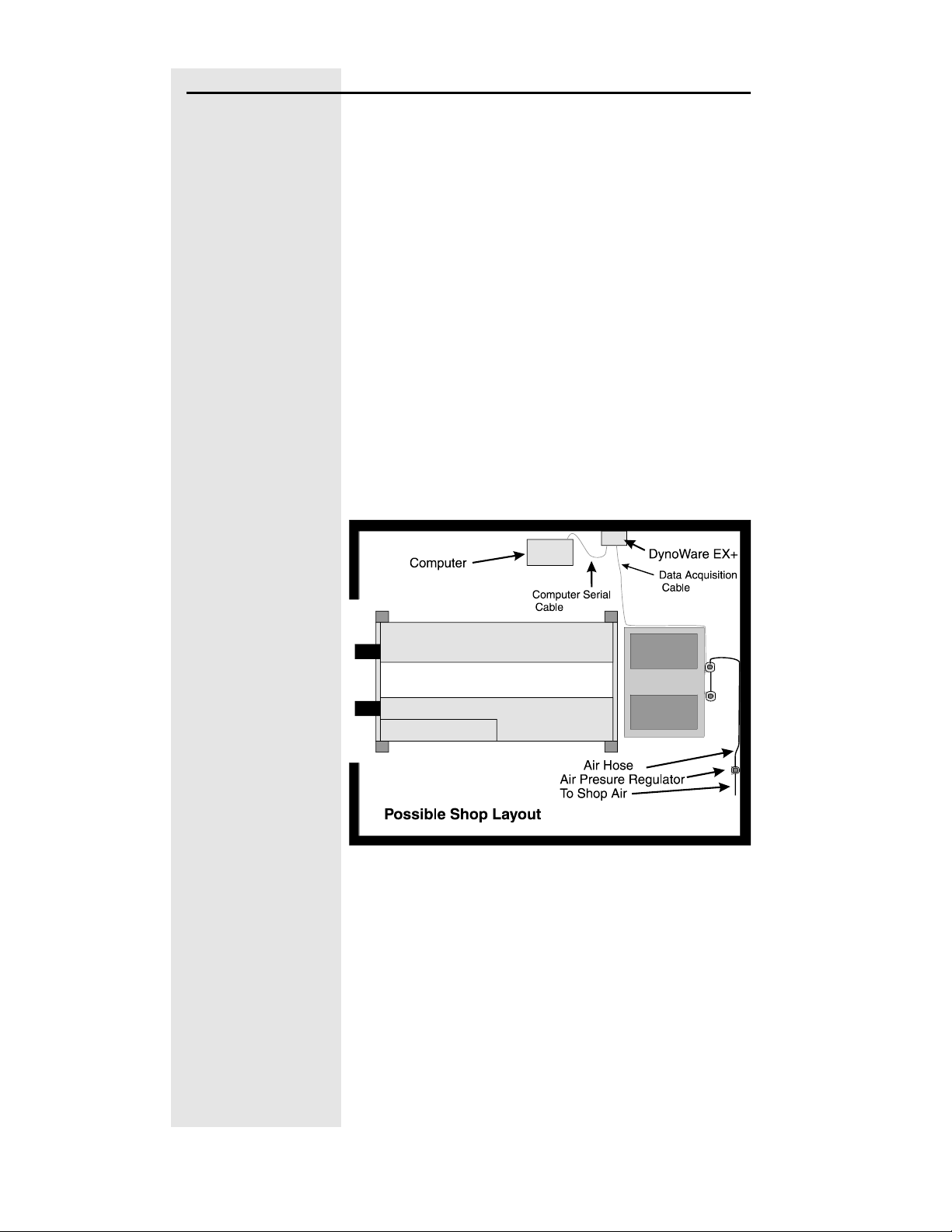
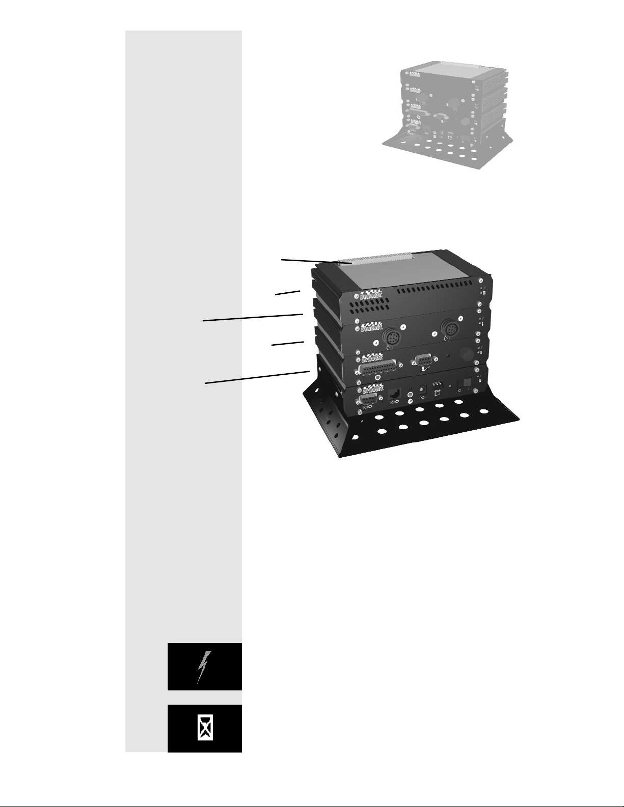
DynoWare EX+ Placement
The DynoWare EX+ system is comprised of
four modules: the CPU module, the
Dynamometer Input/Output module, the
RPM module and the Atmospheric module.
The Dynamometer Input/Output module
connects to the dynamometer. (A 20 foot
(6.1 meter) long cable is provided.) The CPU
module connects to a personal computer.(A
12 foot (3.7 meter) long cable is provided.)
RPM Pickups and a Hand Held Pendant also
connect to the modules. These modules
need to be located where they will be visible
during a dyno run. It is recommended that
they be mounted on a shelf on the wall or on
a cart along side the PC. An optional
extended Hand Held Pendant cable is
available if needed.
Page 8
1 - 4 Document #98219101
Requirements to Unload Truck
When your dyno arrives, you must provide
equipment to unload the dynamometer from
the truck, with skids or forks a minimum of 6
inchs wide by 6 feet long. It must be capable
of lifting and moving at least 8000 pounds
(3642 KG).
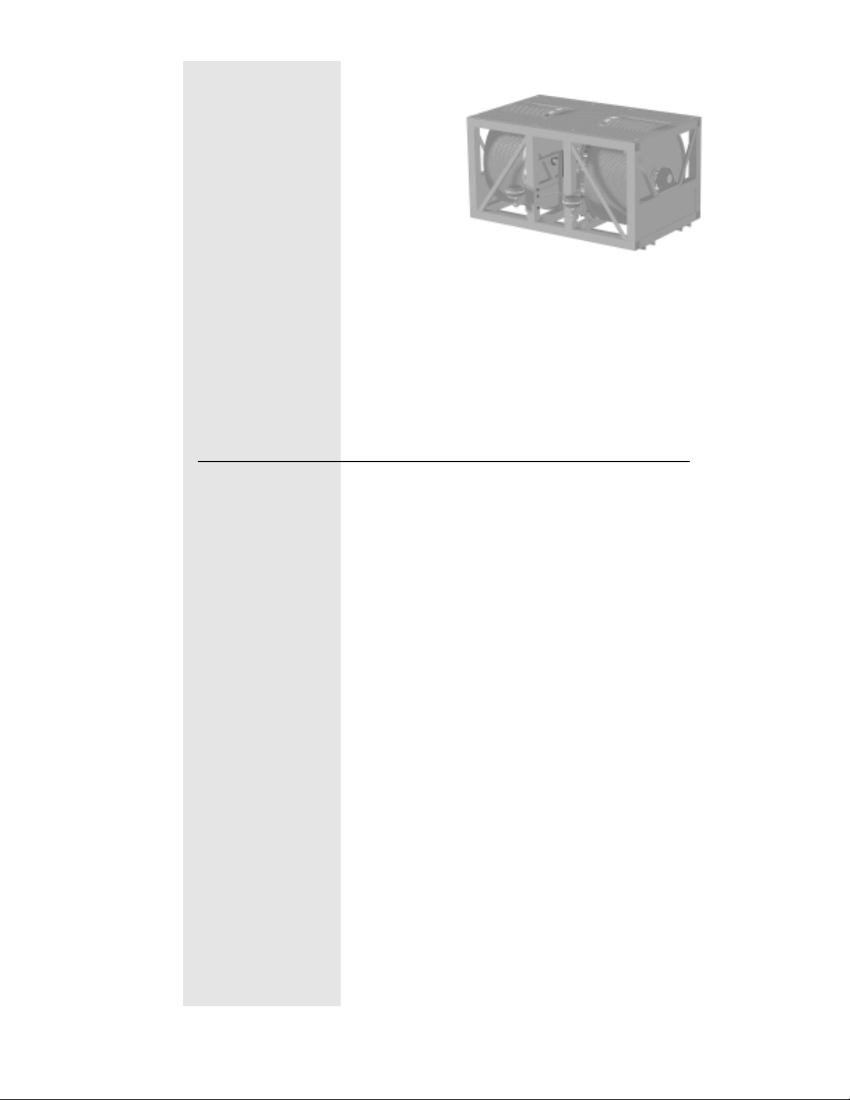
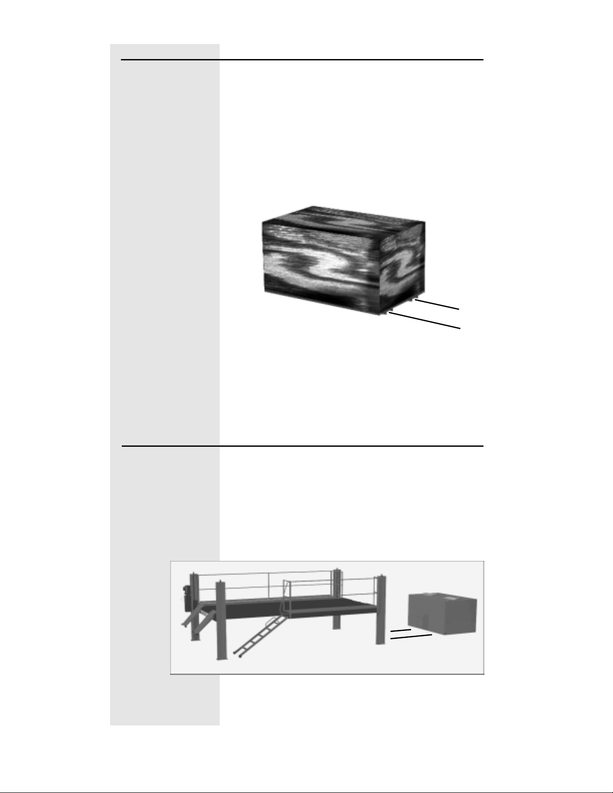
The dyno has 2 C-Channels that run
lengthwise along the bottom of the dyno.
Unload the dynamometer using these
channels.
Requirements to Install the Dynamometer
Installation of the dynamometer requires
equipment capable of lifting and moving at
least 8000 pounds (3642 KG).
Page 9

Other Requirements
Shop Air
The dyno air brake requires a 3/8-inch air hose with a minimum
pressure of 60 psi.
You must provide 3/8-inch air line that will reach from the
dynamometer to the Air Pressure Regulator and another air hose
to connect the regulator to your shop air supply.
Computer Requirements
You will need to provide a computer system to run the WinPEP
software. WinPEP 7 includes complete documentation in online
Help. From the WinPEP 7 menu bar, choose Help WinPEP 7
Help or visit www.winpep.com (accessible with a valid user
name and password).
minimum system requirements recommended systems requirements
• Microsoft® Windows 2000/XP • Microsoft® Windows 2000/XP
• Pentium 800 MHz Processor • 2.4 GHz Processor or greater
• 256 MB of available RAM • 256 MB of available RAM or greater
• one COM port, two COM ports for
Tuning Link
• 800x600, 256 color monitor (SVGA) • 1280x1024 256 color monitor
• 1.2 gigabyte hard drive • 1.2 gigabyte hard drive
• 30 MB of available hard-disk space • 100 MB of available hard-disk space
• CD ROM and floppy disk drive • CD ROM and floppy disk drive
• printer, if hard copies are needed • printer (preferably HP DeskJet®)
• one COM port, two COM ports for
Tuning Link
(SVGA) or better
Document #98219101 1 - 5
Page 10
1 - 6 Document #98219101
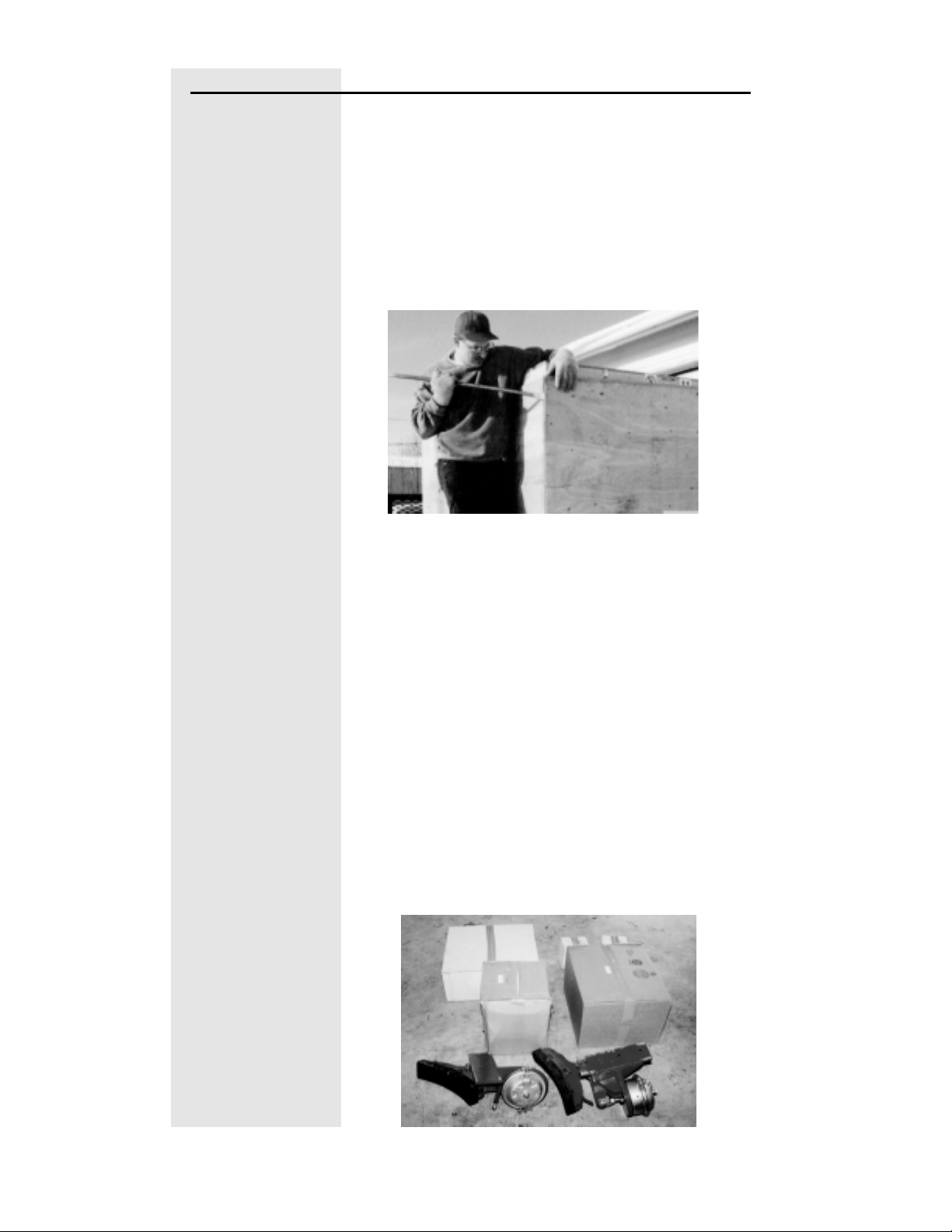
Uncrating the Dyno
Step 1
Use a crowbar or the like to remove the
plywood shipping shell from the
dynamometer.
• Remove catwalk pallet from the top of the
crate (if purchased).
• Remove the top of the crate.
• Remove the sides of the crate.
• Remove the bottom skids and discard.
Step 2
Remove the front and back dyno covers.
Step 3
Carefully remove the cardboard boxes and
brake weldments that are stored within the
dynamometer’s frame.
Page 11
Document #98219101 1 - 7
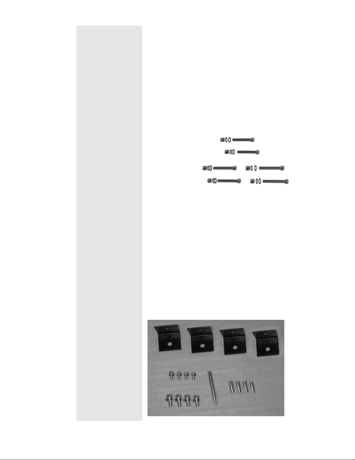
Step 4
Verify the hardware contents as follows:
Brake Hardware:
• 2 brake weldments
(The following are attached to the dyno
frame)
• six 5/8" bolts
• six lock washers
• six flat washers
• six nuts
Mounting Hardware:
• 4- Foot Stands
• 4- 7/16” x 1” Bolts
• 4- 7/16” Flat Washers
• 4- 7/16” Lock Washers
• 4- 3/8” x 1” Bolts
• 4- 3/8” Flat Washers
• 4- 3/8” Lock Washers
• 4- Anchors
• 1- Set Tool
Page 12
1 - 8 Document #98219101
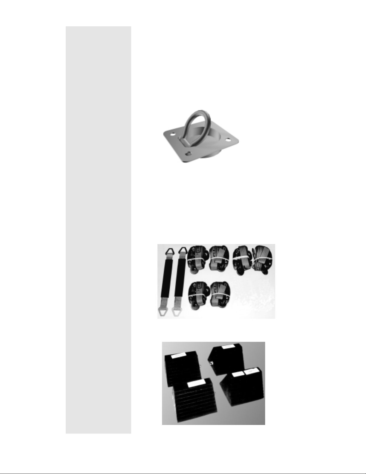
Electronic Hardware:
Pictures and descriptions on page 3- 6 :
Lift Hooks:
• 6 Catwalk Hooks
Straps:
• 2 axle straps
• 2 Long axle straps (not shown)
• 4 ratchet straps
• 2 ratchet straps with sleeves
Chocks (4):
Page 13
Document #98219101 2 - 1
Chapter 2
Hardware Installation
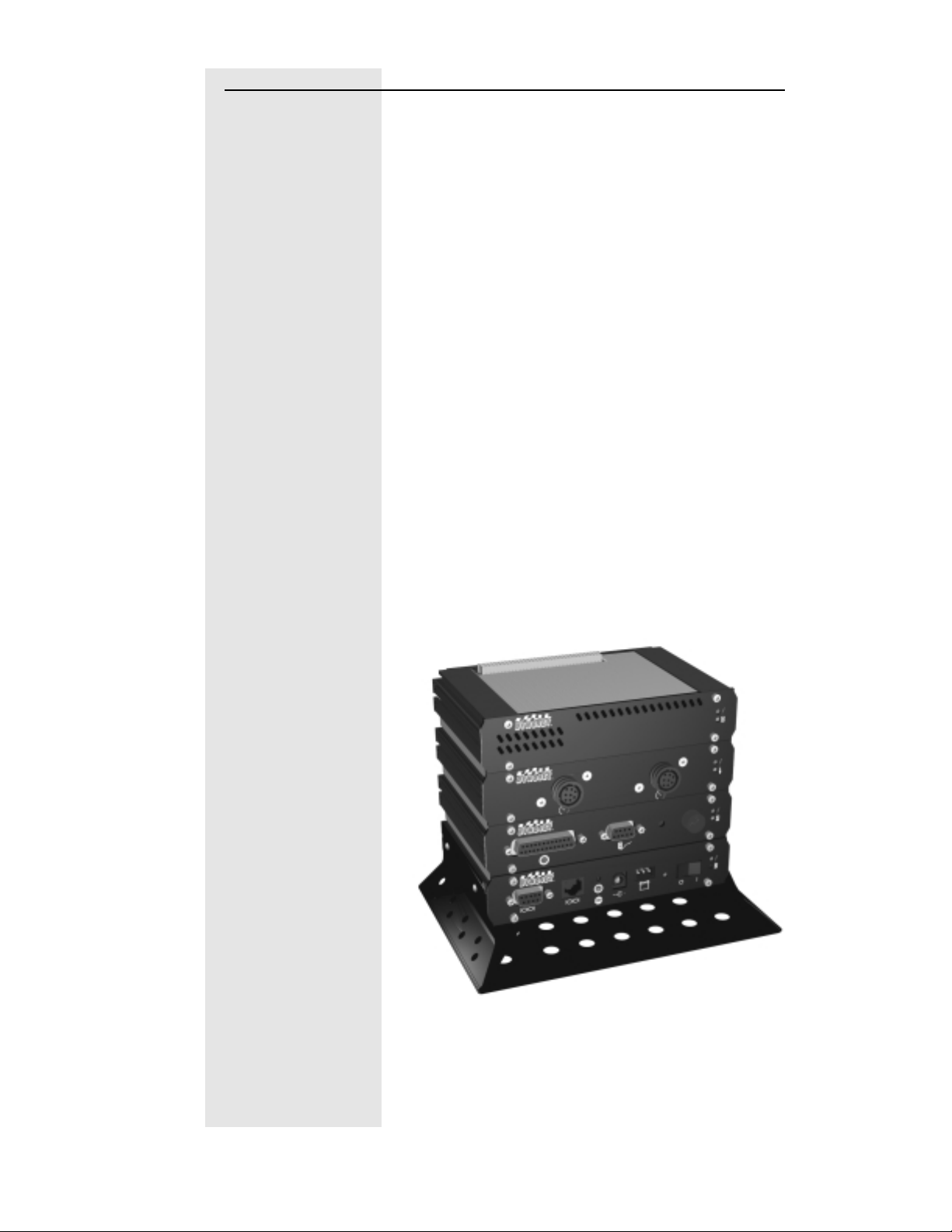
DynoWare EX+
The standard dynamometer electronics package is
comprised of 4 interconnected modules:
Atmospheric Sensing Module:
The atmospheric sensing module measures
absolute pressure, air temperature and relative
humidity. These measurements are used by
WinPEP to correct power and torque
measurements to standard atmospheric conditions
according to a DIN, SAE or other formula.
The green LED glows when the atmospheric
sensing module is receiving power.
The flashing amber LED indicates the module
processor is operating properly.
System Expansion Connector
Atmospheric Sensing Module
RPM Module
Dynamometer Input/Output
Module
CPU Module
Page 14
2 - 2 Document #98219101
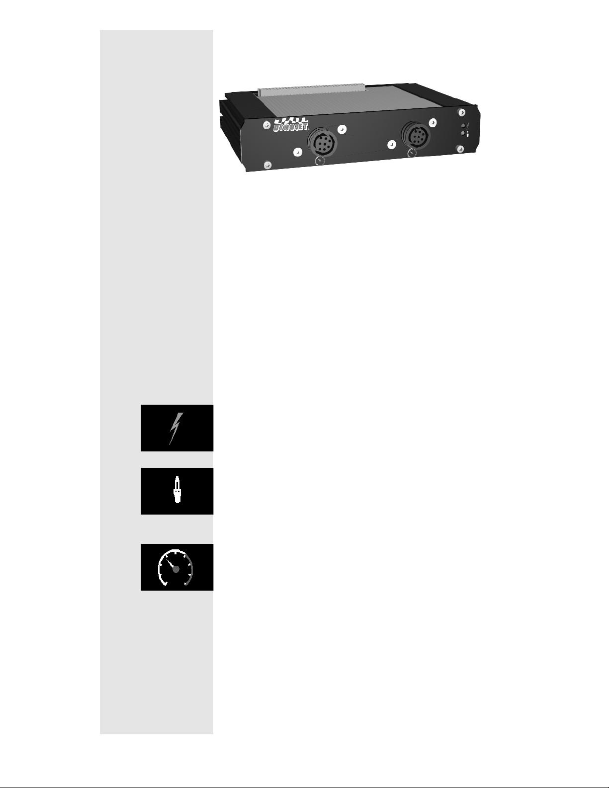
RPM Module:
The RPM module receives and processes signals
from up to 2 inductive pickups for measurement
of engine RPM. Each input has an automatic
gain circuit to compensate for a wide variance of
ignition systems.
The green LED glows when the RPM module is
receiving power.
The amber LED flashes when an RPM signal is
detected. A steady flash rate, proportional to
engine RPM, indicates a good RPM signal.
These connectors are the inputs for both primary
and secondary inductive pickup clips. Either
input may be used with a primary inductive
pickup or a secondary inductive pickup on a
single ended coil. Both inputs can be used for a
wasted spark ignition.
Page 15
Document #98219101 2 - 3
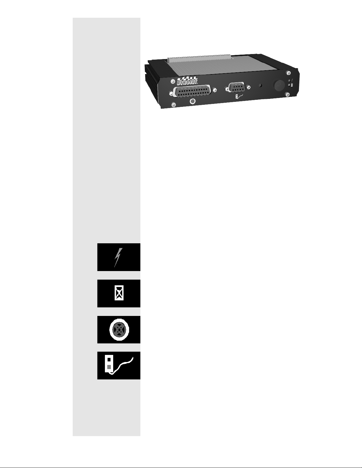
Dynamometer Input/Output Module:
The dynamometer I/O module sends and receives
data from the dynamometer and the hand held
pendant. The module also contains a buzzer and
light which are activated when either the vehicle
or dynamometer speed limit is approached.
The green LED glows when the dynamometer
input/output module is receiving power.
The amber LED flashes proportionally to
dynamometer drum RPM.
This 25-pin receptacle connects to the shielded
cable from the dynamometer.
This 9-pin receptacle connects to the hand held
pendant which houses the button used to
Start/Stop acquiring data. The pendant may also
contain a brake switch.
Page 16
2 - 4 Document #98219101
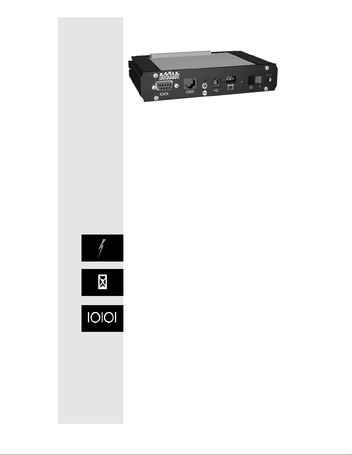
CPU Module:
The CPU module contains a 32-bit processor
which acquires data from the expansion modules
and communicates to the main computer running
the WinPEP software. The processor queries the
expansion modules to determine their identity
and capabilities.
The green LED glows when the CPU module is
receiving power.
The blue LED is lighted when data from the
modules is being acquired and saved.
One of these connectors is used to communicate
to the main computer. The 9-pin receptacle (left)
connects to the PC’s RS-232 serial
communications port. The 8-pin modular
connector (right) provides communications
according to the RS-422/485 specification.
Page 17
Document #98219101 2 - 5
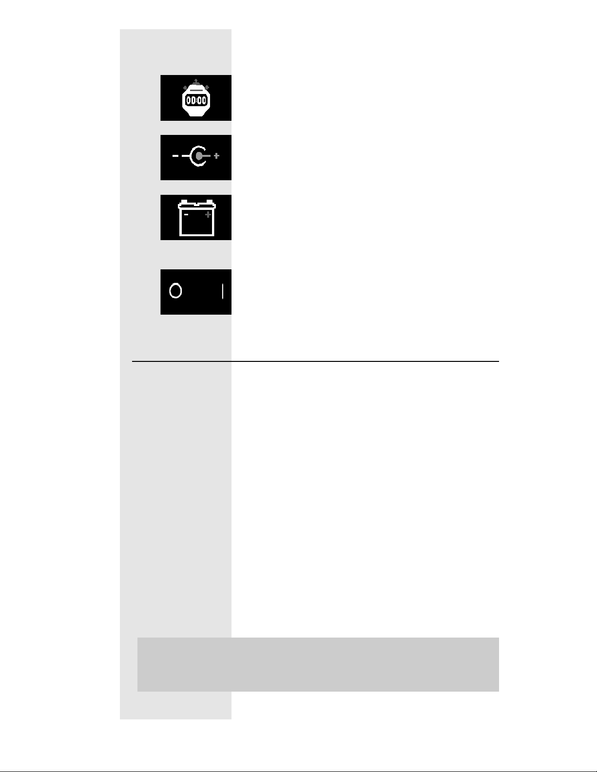
CPU Module: ..... Continued
This connector provides a synchronization signal
to a 3rd-party data acquisition system.
This connector provides 12 Volt DC power to a
3rd-party data acquisition system.
This connector accepts 12 Volt DC power from a
power supply or battery. The adjacent LED
glows bright green when power is properly
connected.
When this switch is on, power is supplied to all
connected modules.
Connecting the DynoWare EX+
Use the cables that came in the DynoWare
package to make the following connections:
• 9-pin shielded serial cable between the RS-232
connector of the CPU Module and a free COM
(serial communications) port on the PC. A 9pin to 25-pin adapter may be required at the
PC.
• 25-pin shielded cable from the dynamometer to
the Dynamometer Input/Output Module.
• 9-pin connector from the hand held pendant to
the Dynamometer Input/Output Module.
• 3-pin plug from the power supply to the CPU
Module with its flat side facing down.
(Refer to the picture on the next page)
Note:
The DynoWare EX+ stack must be
mounted in your shop so as to be easily
seen while making dyno runs.
Page 18
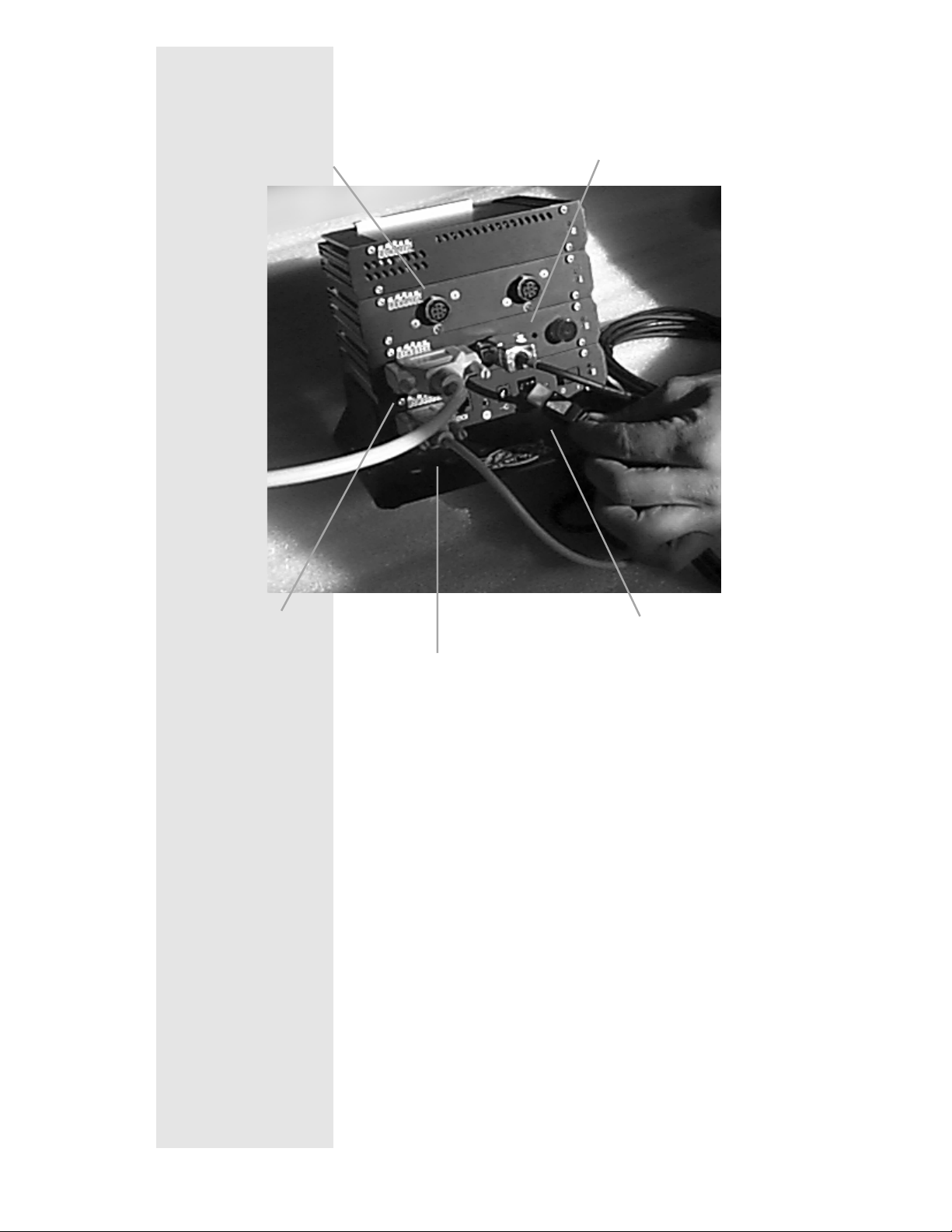
2 - 6 Document #98219101
Remote Switch
Breakout Board to
DynoWare Cable
Cord from Power Supply
Primary Inductive Pickup Cable
(not shown)
Computer Serial Port Cable
Page 19

Document #98219101 3 - 1
Chapter 3
Installing Dynamometer
Now that you have the dynamometer and the Four
Post Lift unpacked you may begin the installation..
Install Lift
Four Post Lift Installation
Refer to the installation guide of the Four
Post Lift for installation.
Install Dynamometer
After complete assembly of the Four Post
Lift, raise and lower the lift a few times to
insure proper operation. Whichever side of
the lift you choose to put the dynamometer
on, the short ramps on the lift must be
removed from that side.
Step 1
With the lift all the way down, move the dyno
into position. (Refer to the diagram in
Appendix A for the location of the dyno
relative to the lift)
Page 20

3 - 2 Document #98219101
Step 2
Install the Feet on the four corners of the
dyno. Use the 7/16” x 1” bolts with flat and
lock washers to secure the feet to the dyno
frame. The bolts should be installed through
the slotted hole in the foot.
Do Not Tighten the Bolts.
Step 3
Once you have the four feet mounted to the
dyno, use a marker to mark the floor
mounting holes. When you have marked all
the holes, remove the feet.
The hardware should
go through the slotted
hole in the foot.
Mark the holes with
a felt tip marker.
Page 21

Document #98219101 3 - 3
Step 4
Using a carbide bit designed for concrete (see
instructions included with anchors) , drill four
1/2” holes in the floor where you made your
marks. The holes should ideally be as deep
as the length of the anchors (approx. 1 5/8”).
Step 5
Place the slotted end of the anchors in the
holes that you drilled. They will most likely
be very snug, so use a brass drift punch and
hammer to drive them down.
Step 6
Use the Set Tool to expand the base of the
anchors. Place the small end of the Set Tool
into the threaded end of the anchor
(threaded end should be up). Drive the Set
Tool with a large hammer until the anchor is
fully seated.
Step 7
Reinstall the feet. The hole that goes into the
Note: Be sure to clean the debris out of the
holes that you drilled.
Page 22

3 - 4 Document #98219101
dyno gets the 7/16” bolt, lock washer, and flat
washer. The 3/8” bolt, lock washer and flat
washer go into the anchor in the floor.
Step 8
Raise the lift and put the roller assembly
portion of the interface kit on the cross beam
of lift at its center line. Refer to the Interface
Assembly Drawing in Appendix A. Position
the roller wheel part of the interface on the lift
so it passes through the tube part of the
interface on the dynamometer.
Page 23

Document #98219101 3 - 5
Step 9
Tighten the roller part of the interface to the
lift’s cross beam. Make sure that it runs
smoothly in the receiver part of the kit.
Installing the Brakes
Use the following steps to install the brakes
on your Dynojet Dyno:
Step 1
Locate the brake hardware. You should have
six 5/8" bolts, six lock washers, six flat
washers, six nuts (mounted on the dyno) and
two brakes.
Step 2
The brakes mount on the inside of the dyno
frame with the air canister on the top. Identify
the left and right brakes. As shown in the
figure above, the brakes can only be
mounted one way.
Step 3
Left
Right
Page 24

3 - 6 Document #98219101
Mount the brakes on the dyno frame. Use
three bolts, three nuts, and three lock
washers on each brake weldment.
- Remove the nuts and lock washers from
the dyno frame leaving the bolts in place.
- Place the brake weldments over the bolts
on the frame.
- Finish the installation of the brake
weldments with the nuts and lock washers.
Step 4
Install the air hose between the brakes, using
the ports on the sides of the air canisters.
Page 25

Document #98219101 3 - 7
Wiring the Dyno Part 1
The following hardware and wires are
shipped in boxes with the dyno except the
DynoWare EX+ (A) that is shipped
separately with the WinPEP software. Refer
to the following page for item descriptions.
Basic Kit
Additional Items for Proportional
Air Brake Systems
C
D
E
F
G
H
J2
J1
B
A
I
K
L
M
R
O
N
S
P
Page 26

3 - 8 Document #98219101
Basic Kit:
A: DynoWare EX+ Modules
B: Air Brake Pressure Regulator
C: Air Brake Control Valve (Replaced by N
with Proportional Air brake systems)
D: DynoWare EX+ Power Supply and Cord
E: Wall Mount for DynoWare EX+
F: DynoWare Cable
G: Dynamometer Control Pendant
H: Serial Port Cable
I: Primary Inductive Cable
J1&2: Secondary Inductive Cables
K: Mounting Hardware
L: Pickup Card
Optional Proportional Air Brake Systems:
(M) Booster Valve Assembly (Replaces C)
(N) Electronic Pressure Regulator (EPR)
(O) DIN Rail (for mounting the EPR)
(P) Temperature Sensor
(Q) Temperature Sensor Bracket
(R) Four1/4" Button Head Allen Bolts
In addition to the parts listed above there is an
EPR cable.
Note:
This section is laid out to aid the operator with
the installation of Standard Air or Proportional
Air braking systems. Steps with “Standard Air“
in front of them are to be followed solely by
operators that are installing the Standard Air
Brake system. Steps with “Proportional Air“ in
front of them are to be followed solely by
operators that are installing the Proportional Air
Brake system. Steps without any
designation are to be followed by both.
Page 27

Document #98219101 3 - 9
Step 1
Install the pickup card.
- Remove the pickup card and the 2 screws
from the bubble bag.
- Attach to the pickup bracket on the dyno so
the optical pickup is facing the axle and the
3 pronged plug is facing away.
- Turn the drum carefully and check to see
that both pickup tabs on the dyno axle go
through the center of the optical pickup on
the pickup card.
Step 2
Prepare the Breakout Board
- Remove the Bubble Bag from the Breakout
Board and bracket.
This tape secures
the Pick Up Card to
the dyno during
shipping.
Break Out Board
Page 28

3 - 10 Document #98219101
- The Data Acquisition Cable is coiled around
the Breakout Board. Uncoil the cable and
Plug the cable into the Pickup Card on the
dyno.
Note: The rest of the instructions for wiring the
dyno follows the catwalk installation.
Page 29

Document #98219101 3 - 11
Catwalk Installation
The following steps will explain how to put the
catwalks on the dyno. The three pictures above
identify the components referred to in these steps.
Step 1
Place the catwalk (A) on the dynamometer above
the brakes, so the lip of the catwalk lays on the
dynamometer frame and butts up against the deck
plate on the dynamometer. Using the 3/8" x 1"
slotted truss head machine screws, secure it to the
top of the dynamometer frame.
Page 30

3 - 12 Document #98219101
Step 2
Using the 3/8" x 1" bolts, loosely secure each
of the four support braces to the
dynamometer and the bottom of the back
catwalk. When the support tubes have been
attached, tighten the bolts on the bottom of
the support tubes. Tighten the bolts at the top
of the support tubes where they attach to the
catwalk.
Step 3
Place the side-catwalks on the dynamometer so
the Dynojet stickers are upright and visible when
looking from the brake side of the dynamometer.
Secure them to the dynamometer with the 3/8" x
1" bolts and to the back plate with the 3/8" x 1"
bolts and nylon insert nuts.
Step 4
Screw the supports (with rotating head) onto
the threaded rods on the side-catwalks.
Place the support tubes over the pegs on the
side of the dynamometer.
Page 31

Document #98219101 3 - 13
Step 5
To adjust the side catwalks so they are level,
the support arms can be turned while on the
pegs and the screw will raise or lower the
side catwalks.
Step 6
Place the railing posts in the pockets and
secure them with the 1/4“ bolts and nuts.
Step 7
String the chain through the holes (using the
end with the bolt) in the top of the railing post.
The chain should start on one end of the side
catwalks, pass through all the posts and
terminate on the opposite side catwalk. Place
the end-cap over the bolt on the end of the
chain and tighten it until the bolt comes to the
end of the end-cap.
Page 32

3 - 14 Document #98219101
Wiring the Dyno Part 2
Standard Air Step 1
(Go on to step 2)
Proportional Air Step 1
Install the electronic regulator.
Measure down and mark 16" and 193/4"
from the top of the right center deck
support.
Drill a7/32" hole in each spot marked
above.
Page 33

Document #98219101 3 - 15
Fasten the DIN rail to the support using two
1/4" self tapping screws (provided).
The electronic pressure regulator snaps
onto the DIN rail, hook one side on the DIN
rail then rotate electronic pressure
regulator toward the DIN rail until it snaps
into place.
Standard Air Step 2
Screw the Air Brake Control Switch into the
top of the right hand air canister.
Page 34

3 - 16 Document #98219101
Proportional Air Step 2
Install the Booster Valve Assembly.
Screw the booster valve assembly into the
right side brake canister. Tighten it so the
air gauge is facing out as shown below.
There are two air lines coming from the
electronic pressure regulator labeled "IN"
and "OUT".
The line labeled "OUT" is connected to the
3-way valve. Push the hose in then hand
tighten the fitting. Pull on the hose to
ensure it is seated properly. If it moves,
tighten the fitting more.
Page 35

Document #98219101 3 - 17
The line labeled "IN" is connected to the
brass cross. Push the hose in then hand
tighten the fitting. Pull on the hose to
ensure it is seated properly. If it moves,
tighten the fitting more.
Standard Air Step 3
(Go on to step 4)
Proportional Air Step 3
Install the Temperature Sensor on the left
rear panel.
Loosely install the left side back cover over
the brake so the Dynojet stickers face out
and upright. (Use the self tapping screws
provided.)
Measure down 24" from the top of the dyno
and mark the left dyno support tube.
Page 36

3 - 18 Document #98219101
Measure from the left side of the dyno to
the right edge of the knurled drum surface
as shown below.
Using the above distance and beginning
24" from the top of the dyno , measure over
and mark the left rear panel as shown
below.
Measure down 24" from the top of the dyno
and mark the mark the left rear panel
where it intersects the previous mark as
shown below.
Page 37

Document #98219101 3 - 19
Center punch and drill a7/32" pilot hole
and then expand it to a
3
/4" hole for the
temperature sensor.
Mount the temperature sensor in the3/4"
hole and adjust it so that it’s tip is
approximately 3" from the surface of the
drum.
Page 38

3 - 20 Document #98219101
Standard Air Step 4
Connect the remaining wires to the Breakout
Board.
Fasten the two black wires into the
connecting block in the connectors marked
with the word BRAKE. (The 2 wires can go
in either order.)
Connect the yellow and black wires from
the Brake Control to the two connectors
marked with the letters -SIG-. (The 2 wires
can go in either order.)
Page 39

Document #98219101 3 - 21
Proportional Air Step 4
Complete the breakout board wiring as in the
following descriptions:
(A) Data acquisition cable coming from the optical
pickup on the dyno shown on the left.
These four wires go to the section of the card
Labeled “DRUM”:
The red wire connects to R1.
The white wire connects to W1.
The black wire connects to B1.
The silver wire connects to S1.
(B) One yellow and one black wire go to the two
connections Labeled “PRESS”. They connect to
the air sensor (shown on the left) located on the
Booster Valve Assembly. They can connect
in either order.
C
B
A
D
E
Page 40

3 - 22 Document #98219101
(C) There are five wires in the cable that
connects the EPR (shown left) to the
breakout board in the spot labeled “Load
Control”:
The black wire connects to V-.
The red wire connects to V+.
The clear wire connects to 0+.
The green wire connects to 0-.
The silver or ground wire connects to SH.
(D) The brake wires (shown left) come from
the air switch on the Booster Valve Assembly.
They connect to the two connectors on the
breakout board labeled “BRAKE”. They can
connect in either order.
(E) The five wires in the cable coming from
the Temperature Sensor (shown left) connect
to the connectors labeled “TEMP”:
The green wire connects to G1.
The white wire connects to W1.
The black wire connects to B1.
The red wire connects to R1.
The silver or ground wire connects to S1.
Connect the Dyno
Step 1
Plug the 25 pin DynoWare Cable into the
bottom of the Breakout Board and hand
tighten the thumb screws.
Page 41

Document #98219101 3 - 23
Step 2
Thread the DynoWare Cable under the dyno
frame.
Proportional Air Step 3
Attach the center panel and tie up the cables
as shown below.
Standard Air Step 3
Attach all the side panels so that the Dynojet
Stickers face outward and the brake wires go
through a slot in the center panel as shown
below.
Page 42

3 - 24 Document #98219101
Step 4
Connect your shop air to the dyno.
Mount the Air Pressure Regulator on the
wall in the shop with the bracket provided.
Connect a supply air hose to the inlet of the
regulator from your shop air supply.
Note:
Make sure the arrow on the regulator is
the same as the direction of the air flow!
Connect a3/8" air hose to the outlet side of
the regulator. Connect the other end of the
air hose to the barbed inlet fitting on the Air
Control Switch (Standard Air) or the
Booster Valve Assembly (Proportional Air)
on top of the right air canister on the dyno.
Note:
The regulator should be set to 60 psi.
Standard Air Step 5
(Go on to step 6)
Proportional Air Step 5
Install the rest of the side panels so the
Dynojet stickers face out and upright. (Use
the self tapping screws provided.)
Proportional Air
Standard Air
Page 43

Document #98219101 3 - 25
Step 6
Check the brakes. The DynoWare Stack must
be on to release the brakes. Slowly rotate the
drums (this can be done manually) then
press the brake button (the red button on the
Hand Held Pendant). The button should light
up and engage the brakes stopping the
drums. Press the button again and the light
will go off, disengaging the brake. If the
brakes do not engage, make sure the
pressure gauge Air Brake Regulator is set to
60 PSI (276 kPa), and check all connections.
If you have any installation questions, call
Dynojet at (800) 992-4993.
Page 44

Page 45

Chapter 4
Basic Dyno Operation
The Dynojet Dynamometer gives state of the art technology,
durability, and accuracy that you need. Dynojet’s advanced
engineering delivers the precise horsepower measurements a
technician needs to make quick and accurate evaluations of
engine performance and drive train problems.
This chapter includes instructions for basic dyno operation. For
more detailed instructions, refer to the WinPEP 7 User Guide.
This manual can also be found on your WinPEP CD or at
www.dynojet.com.
This chapter is divided into the following categories:
• Loading the Vehicle, page 4-2
• Connecting the RPM Pickup, page 4-5
• Pre-Run Inspection, page 4-9
• Making a Test Run, page 4-11
Document #98219101 4 - 1
Page 46

Loading the Vehicle
Use the following steps to load a vehicle on the dyno.
1. Verify your computer is running. Set the dyno brake on by
pressing the red button on the hand held pendant.
2. For four or all-wheel drive vehicles, measure the wheel base
on the vehicle and adjust the 224-4WD dyno to that
dimension before driving the vehicle on the dyno.
CAUTION: Do not make any adjustments with the vehicle on
the dyno.
3. Drive the vehicle onto the dyno and align the vehicle straight
with the dyno.
4. Stop the vehicle when the drive axle is centered on the drum.
center drive axle on dyno drum
center drive axle on dyno drum
adjust wheel base of
224-4WD dyno
4 - 2 Document #98219101
Page 47

5. When the vehicle is positioned properly on the dyno, shut the
engine off.
• If the vehicle has an automatic transmission, place it in
park.
• If the vehicle has a manual transmission, place it in gear.
6. Set the vehicle’s emergency brake.
7. Secure the non-drive wheels using the provided tire chocks.
Do not use tire chocks for four wheel drive vehicles.
8. Attach the tie-down straps.
Rear Wheel Drive
• Attach two tie-down straps from secure anchor points to the
rear of the vehicle. Attach additional tie-down straps from
the rear of the vehicle as shown in Figure 5-2.
• Attach two tie-down straps from secure anchor points to the
front of the vehicle.
Front Wheel Drive
• Attach two tie-down straps from secure anchor points to the
rear of the vehicle.
• Attach two tie-down straps from secure anchor points to the
front of the vehicle. Attach additional tie-down straps
across the front of the vehicle to form a crisscross.
Four Wheel (All-Wheel) Drive
• Attach two tie-down straps from secure anchor points to the
rear of the vehicle. Attach additional tie-down straps across
the rear of the vehicle to form a crisscross.
• Attach two tie-down straps from secure anchor points to the
front of the vehicle. Attach additional tie-down straps
across the front of the vehicle to form a crisscross.
rear wheel drive
Document #98219101 4 - 3
front wheel drive
four wheel drive
Page 48

9. Tighten the tie-down straps evenly making sure that the drive
wheels remain centered on the drum.
CAUTION: The tie-down straps should always be connected to
the vehicle’s solid axle or the suspension control arms. Factory
tie-down hooks connected to the vehicle’s frame may be used on
the end opposite the drive wheels (for example: the front end of a
rear driven vehicle).
10. Release the brake on the vehicle and the dyno.
11. Start the vehicle and put the transmission into first gear or
drive.
12. Press the accelerator pedal so the drums begin turning slowly.
While the drums are slowly turning, get a feel for the stability
of the vehicle.
13. Check all the straps and ensure the vehicle is tracking straight
on the dyno.
4 - 4 Document #98219101
Page 49

Connecting The RPM Pickup
Your Dynojet dynamometer includes a primary wire inductive
pickup and two secondary wire inductive pickups. These small
“clothespin like” inductive pickups are used to sense RPM. An
RPM pickup is required if you want to view torque graphs.
Generally you will use one secondary wire inductive pickup on a
spark plug wire. Vehicles with wasted spark ignition systems may
require two secondary inductive pickups. On a wasted spark
ignition, typically one coil will be connected to two spark plug
wires. Attach one secondary pickup to each of these wires. If the
pickups are connected to two plug wires that do not fire at the
same time, an erratic RPM readout may occur. The primary wire
inductive pickup senses RPM pulses from the coil. Although this
pickup location generally works better, it is harder to find the
correct location to connect the RPM pickup.
Note: If a pickup is not being used, disconnect it from the
dyno electronics to prevent any stray pick up of signals.
The optional Optical Sensor is useful on diesel powered vehicles,
MSD ignitions, and other high RFI ignition systems. For more
detailed information on the Optical Sensor, refer to the Optical
RPM Sensor Installation Guide (P/N 98295109).
CAUTION: Inductive pickups are very fragile. The ferrite core
can easily be damaged and is not covered under warranty.
Dropping, snapping, vibration, and heat can all damage the ferrite
core.
The dyno electronics RPM module contains the electronics that
sense the RPM pulses. An auto-gain circuit looks at only the peak
voltage of the vehicle’ s spark, ig noring the lower voltages to help
reduce electronic noise problems. Wasted spark ignition systems
will produce a lower voltage level on the exhaust stroke than the
compression stroke. By definition of the auto-gain circuit, lower
voltage spark levels will be ignored, missing every other spark the
vehicle would produce.
Document #98219101 4 - 5
Page 50

RPM Pickup Descriptions
RPM pickup description
Secondaries (Non- wasted spark system) Use one secondary pickup. Unplug the
other pickup from the RPM module and
set the degrees between plug fires to 720°
in WinPEP 7.
Secondaries (Wasted spark ignition system) Use two secondary pickups. Attach one
pickup on each spark plug wire on the
same coil and set the degrees between
plug fires to 360° in WinPEP 7.
Primary pickup Attach the primary wire pickup to the
primary side of the coil. Set the degrees
between plug fires by taking 720 (four
cycle engines) or 360 (two cycle engines)
divided by the number of cylinders
multiplied by the number of coils.
For example, the number of degrees
between plug fires on a four cylinder four
cycle engine with dual coils (where each
coil fires two cylinders) is 720/4 x 2=360
degrees.
Optional Optical RPM Sensor Attach the sensor wire to the RPM
module, also be sure to plug in the small
power lead into the CPU module. The
other end of the wire attaches to the
Optical Sensor. Set the degrees between
plug fires to 360° in WinPEP. Refer to
the Optical RPM Sensor Installation
Guide (P/N 98295109).
4 - 6 Document #98219101
Page 51

Connecting the Secondary Inductive
Pickup
The secondary inductive pickup cannot be in contact with, or it’s
connecting wire be crossing, other engine electrical wires or stray
RF interference may result.
1. Clip the secondary inductive pickup around one spark plug
wire.
2. Route the inductive pickup cable clear of devices that produce
electronic noise (spark plug wires, coil wire, coil etc.) to the
dyno electronics RPM module.
Note: Inductive pickup placement is important. Position the
inductive pickup so that it is not making contact with any
other spark plug wires. Separate the spark plug wire from the
spark plug wire bundle for proper operation.
Note: You must ground the vehicle to the dyno for the
electronics to function properly.
connect secondary
inductive pickup on a
single spark plug wire
automobile
distributor
Document #98219101 4 - 7
Page 52

Connecting The Primary Inductive Pickup
The primary inductive pickup cannot be in contact with, or it’ s
connecting wire be crossing, other engine electrical wires or stray
RF interference may result.
1. Clip the primary inductive pickup around the wire to the
primary side of the coil.
2. Route the primary wire cable clear of devices that produce
electronic noise to the dyno electronics RPM module.
Note: You must ground the vehicle to the dyno for the
electronics to function properly.
coil
connect primary
inductive pickup on
the negative side of
the coil
4 - 8 Document #98219101
Page 53

Pre-run Inspection
Perform a vehicle inspection before making a run.
• Check the radiator coolant (if applicable) and oil levels.
• Check the fuel source.
• Rotate the drum and check for rocks caught in the tire tread
that could fly out.
• Check the tire pressure and tire speed rating. Improperly
inflated tires or exceeding the maximum speed rating can
result in premature wear or severe tire damage. Make sure the
tire has no major deficiencies (cracks in sidewalls, tread life,
etc.).
• Visually inspect the vehicle. Make sure it is in safe running
order.
• Make sure ear protection and safety glasses are used when the
dyno is being operated.
• Check the tie-down straps to make sure that they are tight and
secured.
• Check the drive tires to be sure that they are aligned correctly
on the dynamometer’s drums.
• Keep all rotating components clear at all times.
• Only the operator should be near the dyno or the vehicle during
the test.
• Never allow any person(s) to stand behind the dyno or vehicle
when it is being operated.
• Perform any other safety inspections appropriate to running
your vehicle on the dyno.
WARNING: Never allow any person(s) to stand behind the
dyno or vehicle when it is being operated. Only the operator
should be near the dyno or the vehicle during the test.
Before Starting the Engine
Connect an exhaust hose or hoses (if dual exhaust) on the vehicle,
make sure the hose fits over the tail pipe, is not plugged or kinked
and the hose is vented correctly out of the dyno room.
WARNING: Engine exhaust contains poisonous carbon
monoxide gas. Breathing it could cause death. Operate machine in
well ventilated area.
Document #98219101 4 - 9
Page 54

Engine Warm Up
Warm the vehicle’s engine and drivetrain before beginning
testing. Consistent engine temperatures will assure your runs are
repeatable.
After Engine Warm Up
Always leave the vehicle in neutral (automatic transmission) or in
first gear (manual transmission), with the engine off, and make
sure the park brake and the dyno brake are on when you get off
the vehicle on the dyno.
• Fix any fuel, oil, or coolant leaks that may have shown up after
engine warm up and check the carburetor for leaks.
• Any loud or unusual engine noises or excessive exhaust smoke
should be resolved before continuing.
4 - 10 Document #98219101
Page 55

Making a Test Run
Dyno runs provide safe, reliable road testing right in the shop.
The dyno allows you to measure, record, and diagnose
performance problems quickly. The dyno combined with
WinPEP 7 produces consistent, easily interpretable power graphs.
Use the following instructions to ensure repeatable and accurate
measurements.
1. Verify the vehicle is secured properly.
2. Place the vehicle in a low gear and release the dyno brake
using the hand held pendant.
3. Slowly accelerate the vehicle to 20 m.p.h.
4. Test the tachometer operation.
• Rev the engine. The gauges on the computer screen should
be moving. If the tachometer is moving but not registering
the correct RPM values, the number of degrees of
revolution of the crank shaft (the plug fires number) is
incorrect.
• Stop the vehicle, return to the MakeRun Configuration
dialog box, and enter the correct value for plug firing order.
5. Press the red brake button to apply 100% braking and slow
down the vehicle.
CAUTION: Using the vehicle’s rear brake to stop the drum at
speeds over 30 m.p.h. can severely over heat the rear brake parts.
Dynojet dynamometers with the air brake or eddy current brake
accessory can be used to slow the vehicle and drum to a full stop
at any speed. The vehicle’ s brake should be used in an emer gency
stop situation only.
6. Shut the engine off and put the vehicle in gear (manual
transmission) or neutral (automatic transmission).
7. Set the vehicle’s parking brake and leave the dyno brake on.
8. Perform a final inspection.
• Verify the drive tire’s alignment on the dyno drums.
• Make any adjustments to the tie-down straps as needed.
• Perform any other safety checks that you deem appropriate
to your particular situation.
You are now ready to make a high speed run on the dyno. Refer to
your WinPEP 7 User Guide for more detailed instructions.
Document #98219101 4 - 11
Page 56

Page 57

Document #98219101 A - 1
Appendix A
- Square the face of the dyno up to the face
of the four post lift. The distance between
the two is 4”.
Center Line of Dyno
and Four Post Lift
Lift Tube with
Roller Portion of
the Interface Kit
Relative Dyno and Four Post Lift Location
Page 58

A - 2 Document #98219101
Appendix A
 Loading...