

Page 1
Page 2

©2004-2008 Dynojet Research, Inc. All Rights Reserved.
Maintenance Guide For Model 224, Model 224 with 4WD, Model 424x, and Model 248
Automotive Dynamometers.
This manual is copyrighted by Dynojet Research, Inc., hereafter referred to as Dynojet,
and all rights are reserved. This manual is furnished under license and may only be used
or copied in accordance with the terms of such license. This manual is furnished for
informational use only, is subject to change without notice, and should not be construed
as a commitment by Dynojet. Dynojet assumes no responsibility or liability for any error
or inaccuracies that may appear in this manual. Except as permitted by such license, no
part of this manual may be reproduced, stored in a retrieval system, or transmitted, in any
form or by any means, electronic, mechanical, recording, or otherwise, without the prior
written permission of Dynojet.
The Dynojet logo is a trademark of Dynojet Research, Inc.
Any trademarks, trade names, service marks, or service names owned or registered by any
other company and used in this guide are the property of their respective companies.
Dynojet Research, Inc., 2191 Mendenhall Drive, North Las Vegas, Nevada 89031, USA.
Printed in USA.
Part Number: 98119101 Version 3 (03/2008)
Page 3

T
ABLE OF
C
ONTENTS
Auto Dyno Maintenance
Introduction . . . . . . . . . . . . . . . . . . . . . . . . . . . . . . . . . . . . . . . . . . . . . . . . . . . 2
Conventions Used In This Manual . . . . . . . . . . . . . . . . . . . . . . . . . . . . . . . . 2
Technical Support . . . . . . . . . . . . . . . . . . . . . . . . . . . . . . . . . . . . . . . . . . . . 2
Model 224 Dynos with Air Over HyDraulic (AOH) Brake Systems . . . . . . . 3
Things to Check . . . . . . . . . . . . . . . . . . . . . . . . . . . . . . . . . . . . . . . . . . . . . . 3
Maintaining the Model 224 AOH Drum Brake Shoe Clearance . . . . . . . . . . . 4
Model 224 Dynos with Spring Applied Air Release (SAAR) Brake System . 6
Things to Check . . . . . . . . . . . . . . . . . . . . . . . . . . . . . . . . . . . . . . . . . . . . . . 6
Verifying the SAAR Brake Pressure . . . . . . . . . . . . . . . . . . . . . . . . . . . . . . . . 7
Maintaining the SAAR Brake Shoe Clearance . . . . . . . . . . . . . . . . . . . . . . . . 8
Changing the SAAR Brake Shoes . . . . . . . . . . . . . . . . . . . . . . . . . . . . . . . . 10
4WD Attachment for Model 224 Dynos . . . . . . . . . . . . . . . . . . . . . . . . . . . 16
Things to Check . . . . . . . . . . . . . . . . . . . . . . . . . . . . . . . . . . . . . . . . . . . . . 16
Filling the Air Motor Lubricator . . . . . . . . . . . . . . . . . . . . . . . . . . . . . . . . . 17
Adjusting the Air Motor Lubricator . . . . . . . . . . . . . . . . . . . . . . . . . . . . . . . 18
Inspecting the Rail Brake Clearance . . . . . . . . . . . . . . . . . . . . . . . . . . . . . . 19
Model 424x All-Wheel Drive Dynos . . . . . . . . . . . . . . . . . . . . . . . . . . . . . . 20
Things to Check . . . . . . . . . . . . . . . . . . . . . . . . . . . . . . . . . . . . . . . . . . . . . 20
Filling the Air Motor Lubricator . . . . . . . . . . . . . . . . . . . . . . . . . . . . . . . . . 21
Adjusting the Air Motor Lubricator . . . . . . . . . . . . . . . . . . . . . . . . . . . . . . . 22
Verifying the SAAR Brake Pressure . . . . . . . . . . . . . . . . . . . . . . . . . . . . . . . 23
Maintaining the SAAR Brake Shoe Clearance . . . . . . . . . . . . . . . . . . . . . . . 24
Changing the SAAR Brake Shoes . . . . . . . . . . . . . . . . . . . . . . . . . . . . . . . . 25
Checking the Air Can Sleeve Retraction . . . . . . . . . . . . . . . . . . . . . . . . . . . 26
Model 248 Dynos . . . . . . . . . . . . . . . . . . . . . . . . . . . . . . . . . . . . . . . . . . . . . 27
Things to Check . . . . . . . . . . . . . . . . . . . . . . . . . . . . . . . . . . . . . . . . . . . . . 27
Checking the 248 Drum Brake Shoe Clearance . . . . . . . . . . . . . . . . . . . . . 28
Maintenance Guide for Automotive Dynamometers
i
Page 4

Page 5

A
UTO
D
YNO
M
AINTENANCE
This document provides instructions for performing maintenance on the model 224
dynamometer (dyno), the model 224 dyno with the four wheel drive (4WD)
attachment, the model 224-2 dyno, the model 424x dyno, and the model 248 dyno. To
ensure safety and accuracy in the procedures, perform the procedures as they are
described.
Document Part Number: 98119101
Version 3
Last Updated: 03-19-08
Maintenance Guide for Automotive Dynamometers
1
Page 6
AUTO DYNO MAINTENANCE
Introduction
INTRODUCTION
. . . . . . . . . . . . . . . . . . . . . . . . . . . . . . . . . . .
You may have a model 224 dyno configured with one drum for testing two-wheel
drive vehicles, or with two drums for testing four-wheel drive vehicles. Model 224
dynos also may use either the Air Over Hydraulic (AOH) brake or the Spring Applied
Air Release brake (SAAR). Model 424x dynos all use the SAAR brake and have two
dyno drums for testing four-wheel drive cars. Or you may have a model 248 dyno.
Make sure to perform all of the maintenance procedures for your dyno configuration.
CONVENTIONS USED IN THIS MANUAL
The conventions used in this manual are designed to protect both the user and the
equipment.
example of convention description
The Caution icon indicates a potential hazard to the
dynamometer equipment. Follow all procedures
exactly as they are described and use care when
performing all procedures.
The Warning icon indicates potential harm to the
person performing a procedure and/or the
dynamometer equipment.
TECHNICAL SUPPORT
For assistance, please contact Dynojet Technical Support at 1-800-992-3525, or write
to Dynojet at 2191 Mendenhall Drive, North Las Vegas, NV 89031.
Visit us on the World Wide Web at www.dynojet.com where Dynojet provides state of
the art technical support, on-line shopping, and press releases about our latest
product line.
2
Maintenance Guide for Automotive Dynamometers
Page 7
AUTO DYNO MAINTENANCE
03
Model 224 Dynos with Air Over HyDraulic (AOH) Brake Systems
MODEL 224 DYNOS WITH AIR OVER HYDRAULIC (AOH) BRAKE SYSTEMS
. . . . . . . . . . . . . . . . . . . . . . . . . . . . . . . . . . .
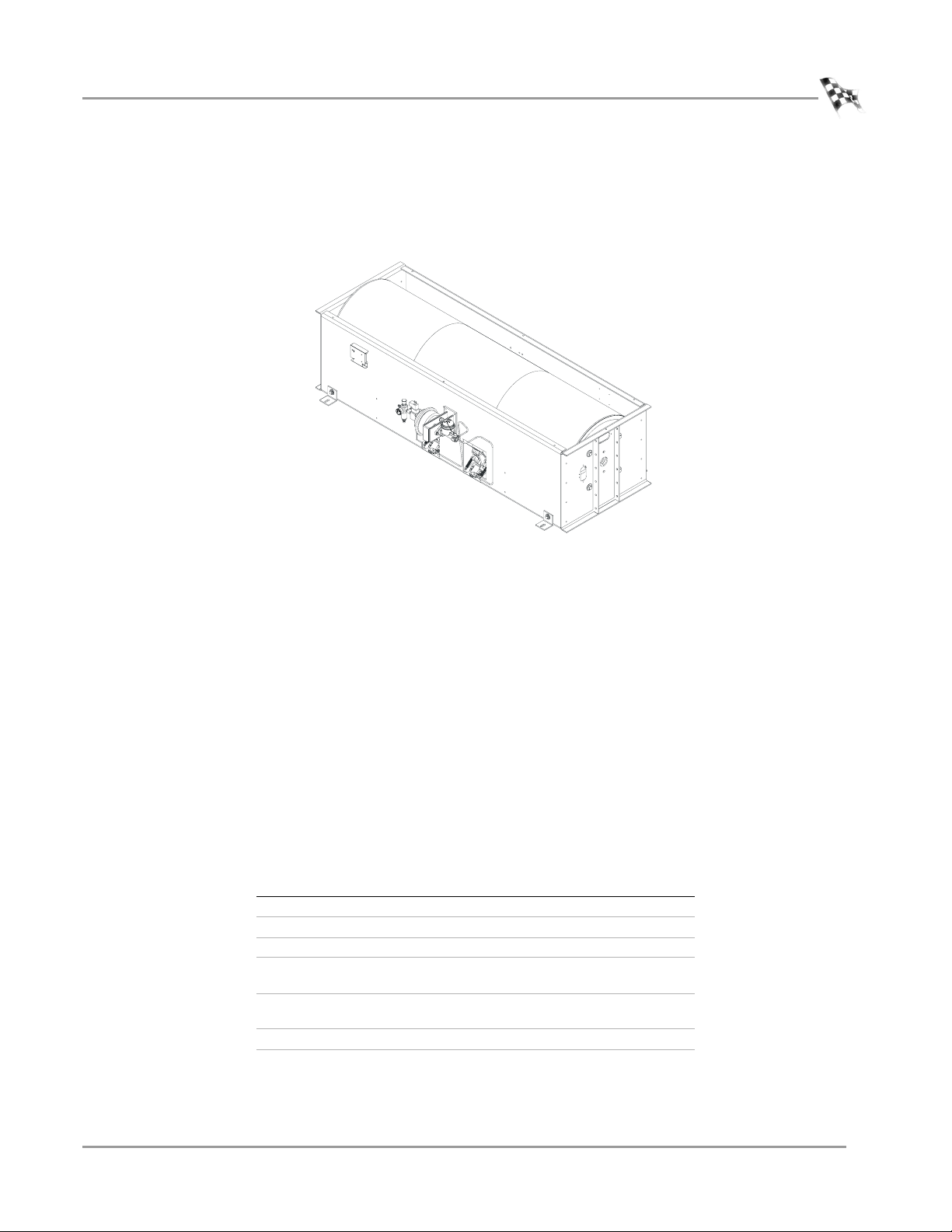
This section covers maintenance items for model 224 dynos with a single drum and
AOH braking.
AD2
Figure 1: Model 224 with Air Over Hydraulic (AOH) Brakes
THINGS TO CHECK
• Check all air fittings for leaks monthly. Correct any leaks found.
• Once per month verify that the drum brake pressure gauge reads 55 to 65psi
(380 - 450kPa). Adjust the regulator if the pressure is out of specification.
• Once per month check the drum brake shoe clearance. Refer to page 4 for more
information.
•Dyno Bearing Grease:
Under steady use, over 25 runs per day, each bearing should receive .65oz (19 ml)
of a recommended grease every 2 months.
Under occasional use, less than 25 runs per day, each bearing should receive
.65oz (19 ml) of a recommended grease every six months.
Recommended Grease:
grease specification description
thickener Lithium 12 Hydroxy Stearate
oil Petroleum
thickness NLGI 2
operating temperature
(Fahrenheit)
operating temperature
(Celsius)
EP additive yes
examples Mobil Mobilith AW-2
-20°F to 200°F, intermittent to 250°F
-29°C to 93°C, intermittent to 121°C
Version 3 Maintenance Guide for Automotive Dynamometers
3
Page 8
AUTO DYNO MAINTENANCE
Model 224 Dynos with Air Over HyDraulic (AOH) Brake Systems
MAINTAINING THE MODEL 224 AOH DRUM BRAKE SHOE CLEARANCE
The 224 AOH drum brake shoe clearance must be checked once per month. If you
have upgraded your 224 dyno to use the Spring Applied Air Release (SAAR) braking
system, refer to “Maintaining the SAAR Brake Shoe Clearance” on page 8.
1 Remove the air from the system.
1a Shut off or disconnect the air supply to the dyno, and follow lock out
procedure.
1b Press the red button on the pendant to activate the drum brakes; the button
will be lit.
1c Using the red button on the pendant, cycle the drum brakes on and off
several times until all of the air is released from the system.
2 Remove the covers as necessary to provide safe working access to the dyno.
3 Measure the gap between the brake shoe and the drum surface. This gap should
be .125 inch - .375 inch (3mm - 10mm).
4 If the brake shoe clearance is out of specification, perform the following steps:
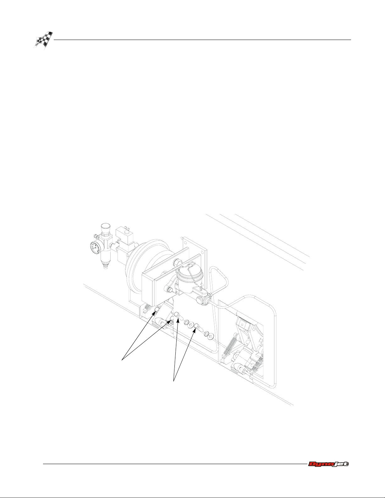
4a Remove the two 3/8-inch bolts and washers that secure the brake slave
cylinder to the dyno frame.
AD204
4
Maintenance Guide for Automotive Dynamometers
remove bolts
and washers
Figure 2: 224 Dyno AOH Brake—Remove the Bolts from Brake Slave Cylinder
remove bolts
and washers
Page 9
AUTO DYNO MAINTENANCE
Model 224 Dynos with Air Over HyDraulic (AOH) Brake Systems
4b Pull the slave cylinder away from the dyno being careful not to kink the
brake line.
4c Screw the brake piston rod in to increase brake shoe clearance or out to
decrease brake shoe clearance. Refer to Figure 3.
4d Attach the slave cylinder using the bolts and washers removed earlier.
4e Recheck the brake shoe clearance. No part of the brake shoe should touch
the drum.
Note: If you cannot adjust the brakes to specification, you will need new brake
shoes. Contact Dynojet.
5 Turn on or reconnect the air supply and verify the drum brakes operate before
replacing the covers and using the dyno.
AD205
screw brake piston rod
in or out to adjust brake
clearance
carefully pull slave
cylinder away to expose
the brake piston rod
Figure 3: 224 Dyno AOH Brake—Pull the Cylinder Away
Version 3 Maintenance Guide for Automotive Dynamometers
5
Page 10
AUTO DYNO MAINTENANCE
Model 224 Dynos with Spring Applied Air Release (SAAR) Brake System
MODEL 224 DYNOS WITH SPRING APPLIED AIR RELEASE (SAAR) BRAKE SYSTEM
. . . . . . . . . . . . . . . . . . . . . . . . . . . . . . . . . . .
This section covers maintenance items for model 224 dynos with the SAAR brake.
THINGS TO CHECK
• Check all air fittings for leaks monthly. Correct any leaks found.
• Once per month verify the drum brake pressure gauge reads 100psi (690kPa).
Adjust the regulator if the pressure is out of specification. Refer to “Verifying the
SAAR Brake Pressure” on page 7 for more information.
• Check the drum brake shoe clearance. Refer to “Maintaining the SAAR Brake Shoe
Clearance” on page 8 for more information.
•Dyno Bearing Grease:
Under steady use, over 25 runs per day, each bearing should receive .65oz (19 ml)
of a recommended grease every 2 months.
Under occasional use, less than 25 runs per day, each bearing should receive
.65oz (19 ml) of a recommended grease every six months.
Recommended Grease:
grease specification description
thickener Lithium 12 Hydroxy Stearate
oil Petroleum
thickness NLGI 2
operating temperature
(Fahrenheit)
operating temperature
(Celsius)
EP additive yes
examples Mobil Mobilith AW-2
-20°F to 200°F, intermittent to 250°F
-29°C to 93°C, intermittent to 121°C
6
Maintenance Guide for Automotive Dynamometers
Page 11
Model 224 Dynos with Spring Applied Air Release (SAAR) Brake System
VERIFYING THE SAAR BRAKE PRESSURE
1 Verify the SAAR brake pressure gauge reads 100psi (690kPa).
2 Using the knob, adjust the regulator until the correct pressure is achieved.
brake pressure
regulator
AUTO DYNO MAINTENANCE
AB096
use knob to adjust
regulator until correct
pressure is achieved
0
brake pressure gauge
should read 100psi
(690kPA)
Figure 4: 224 Dyno—Verify the SAAR Brake Pressure and Adjust Using the Regulator
AB095
Version 3 Maintenance Guide for Automotive Dynamometers
7
Page 12

AUTO DYNO MAINTENANCE
Model 224 Dynos with Spring Applied Air Release (SAAR) Brake System
MAINTAINING THE SAAR BRAKE SHOE CLEARANCE
1 Verify the area is clear and the dyno can be operated safely.
2 Power up the dyno electronics.
3 Using the pendant, turn the brake to the off position. This will release the SAAR
brake by moving the brake shoe away from the drum.
Keep hands and fingers clear when operating dyno.
4 Measure the gap between the brake shoe and the drum surface. This gap should
be between .125 inch - .375 inch (3mm - 10mm).
Note: For clarity, the dyno frame is shown transparently to reveal the drum.
Note: The mounting bracket shown is used with the SAAR upgrade. Factory
installed SAAR brakes use a slightly different bracket.
brake shoe
drum
measure gap
AB094
Figure 5: 224 SAAR Brake—Measure the Gap Between the Brake Shoe and Drum
8
Maintenance Guide for Automotive Dynamometers
Page 13

AUTO DYNO MAINTENANCE
Model 224 Dynos with Spring Applied Air Release (SAAR) Brake System
5 If the brake shoe clearance is out of specification, loosen the upper nut on the air
can rod.
6 Adjust the lower nut until the brake shoes are .25 inch (6mm) away from the dyno
drum.
7 Tighten the upper nut on the air can rod down onto the brake actuating tube to
sandwich the tube between the two nuts.
8 Torque the lower nut to 110 foot-pounds.
If you cannot adjust the brakes to specification, you will need new brake shoes.
Contact Dynojet.
air can rod
upper nut
brake actuating tube
BR032
lower nut
Figure 6: 224 SAAR Brake—Adjust the Brake Shoe Clearance
Version 3 Maintenance Guide for Automotive Dynamometers
9
Page 14

AUTO DYNO MAINTENANCE
Model 224 Dynos with Spring Applied Air Release (SAAR) Brake System
CHANGING THE SAAR BRAKE SHOES
1 Apply air to the brake system.
Air pressure to the brake system must be maintained while changing the SAAR
brake shoes.
2 Release the brakes.
2a Turn on the dyno electronics.
2b Verify the brake button on the pendant is not lit.
3 Remove the nut from the bottom air can rod and set aside.
Figure 7: 224 SAAR Brake—Remove the Nut from the Bottom Air Can Rod
10
Maintenance Guide for Automotive Dynamometers
air can rod
nut
Page 15

Model 224 Dynos with Spring Applied Air Release (SAAR) Brake System
4 Slowly lower the pressure using the regulator.
The air can rod will retract from the tube.
Note: Verify the rod does not bind on the tube.
AUTO DYNO MAINTENANCE
regulator
air can rod
Figure 8: 224 SAAR Brake—Retract the Air Can Rod from the Tube
Version 3 Maintenance Guide for Automotive Dynamometers
tube
11
Page 16

AUTO DYNO MAINTENANCE
Model 224 Dynos with Spring Applied Air Release (SAAR) Brake System
5 Slide the tube out and set aside.
tube
Figure 9: 224 SAAR Brake—Slide the Tube Out
6 Using the access holes in the dyno frame, remove the cotter key from each brake.
7 Remove the pin from each brake.
Note: For clarity, the drum is not shown.
pin
top view
drum not shown
for clarity
cotter key
Figure 10: 224 SAAR Brake—Remove the Cotter Key and Pin
12
Maintenance Guide for Automotive Dynamometers
Page 17

Model 224 Dynos with Spring Applied Air Release (SAAR) Brake System
8 Remove each brake arm assembly.
AUTO DYNO MAINTENANCE
brake arm assembly
brake shoe
cotter key
Figure 11: 224 SAAR Brake—Remove the Brake Arm Assembly
9 Remove the cotter key from the brake arm assembly.
10 Remove the pin.
11 Remove the retainer and shoe.
12 Install the new brake shoe and replace the retainer.
Note: Verify the brake shoe is secure.
13 Replace the pin and cotter key.
retainer
pin
Figure 12: 224 SAAR Brake—Replace the Brake Shoe
cotter key
pin
brake shoe
retainer
Version 3 Maintenance Guide for Automotive Dynamometers
13
Page 18

AUTO DYNO MAINTENANCE
Model 224 Dynos with Spring Applied Air Release (SAAR) Brake System
14 Replace each brake arm assembly using the pin and cotter key removed earlier.
Refer to Figure 10.
15 Slide the tube in.
16 Slowly raise the pressure using the regulator.
The air can rod will go through the tube.
Note: Verify the rod does not bind on the tube.
regulator
Figure 13: 224 SAAR Brake—Replace the Air Can Rod Through the Tube
14
Maintenance Guide for Automotive Dynamometers
air can rod
tube
Page 19

AUTO DYNO MAINTENANCE
Model 224 Dynos with Spring Applied Air Release (SAAR) Brake System
17 Replace the nut, removed earlier, on the bottom air can rod.
18 Adjust the brake shoe clearance as necessary. Refer to “Maintaining the SAAR
Brake Shoe Clearance” on page 8 for more information.
19 Press the red button on the pendant to activate the drum brakes; the button will
be lit.
air can rod
Figure 14: 224 SAAR Brake—Replace the Nut on the Bottom Air Can Rod
Version 3 Maintenance Guide for Automotive Dynamometers
nut
15
Page 20

AUTO DYNO MAINTENANCE
4WD Attachment for Model 224 Dynos
4WD ATTACHMENT FOR MODEL 224 DYNOS
. . . . . . . . . . . . . . . . . . . . . . . . . . . . . . . . . . .
This section covers maintenance items for model 224 dynos with the 4WD
attachment.
THINGS TO CHECK
• Check customer supplied air filter/dryer daily, empty and clean as necessary.
• Inspect the 4WD dyno movement rails for debris once per month. Clear any debris
from the rails.
• Check all air fittings for leaks monthly. Correct any leaks found.
• Once per month maintain the brake pressure and brake shoe clearance. For AOH
brakes refer to page 3. If you have upgraded to the SAAR brake, see page 6.
• Adjust the lubrication provided by the air motor lubricator. Refer to “Adjusting the
Air Motor Lubricator” on page 18 for more information.
• Check the air motor lubricator once per month and fill as necessary. Refer to
“Filling the Air Motor Lubricator” on page 17 for more information.
•Dyno Bearing Grease:
Under steady use, over 25 runs per day, each bearing should receive .65oz (19 ml)
of a recommended grease every 2 months.
Under occasional use, less than 25 runs per day, each bearing should receive
.65oz (19 ml) of a recommended grease every six months.
Recommended Grease:
grease specification description
thickener Lithium 12 Hydroxy Stearate
oil Petroleum
thickness NLGI 2
operating temperature
(Fahrenheit)
operating temperature
(Celsius)
EP additive yes
examples Mobil Mobilith AW-2
-20°F to 200°F, intermittent to 250°F
-29°C to 93°C, intermittent to 121°C
16
Maintenance Guide for Automotive Dynamometers
Page 21

FILLING THE AIR MOTOR LUBRICATOR
3
Check the air motor lubricator once per month and fill as necessary.
1 Disconnect the air before removing the lubricator bowl.
2 Shut off or disconnect the air supply to the dyno, and follow lock out procedure.
3 Press and hold the dyno in or out movement switch until you cannot hear any air
going through the movement motor.
4 Before running the Gast Air Motor, remove the lubricator bowl and fill the bowl
with oil.
Note: Use a non-detergent SAE #10 automotive engine oil (Gast Part #AD220).
AUTO DYNO MAINTENANCE
4WD Attachment for Model 224 Dynos
remove bowl and
fill to line with oil
BR04
Figure 15: 224 4WD Attachment—Check Air Motor Lubricator
Version 3 Maintenance Guide for Automotive Dynamometers
17
Page 22

AUTO DYNO MAINTENANCE
4WD Attachment for Model 224 Dynos
ADJUSTING THE AIR MOTOR LUBRICATOR
Use the following steps to adjust the amount of oil provided by the air motor
lubricator.
1 Turn the top knob on the air motor lubricator clockwise until it shuts off the flow
of oil.
2 Back off the knob one turn counter-clockwise to start the flow of oil.
3 Adjust the knob as needed between one turn and fully on (turning counter-
clockwise) as needed for the particular environment in your dyno room.
turn knob
clockwise to shut
off oil, back off one
turn counter-
clockwise to start
the flow of oil
AD206
Figure 16: 224 4WD Attachment—Adjust the Air Motor Lubricator
18
Maintenance Guide for Automotive Dynamometers
Page 23

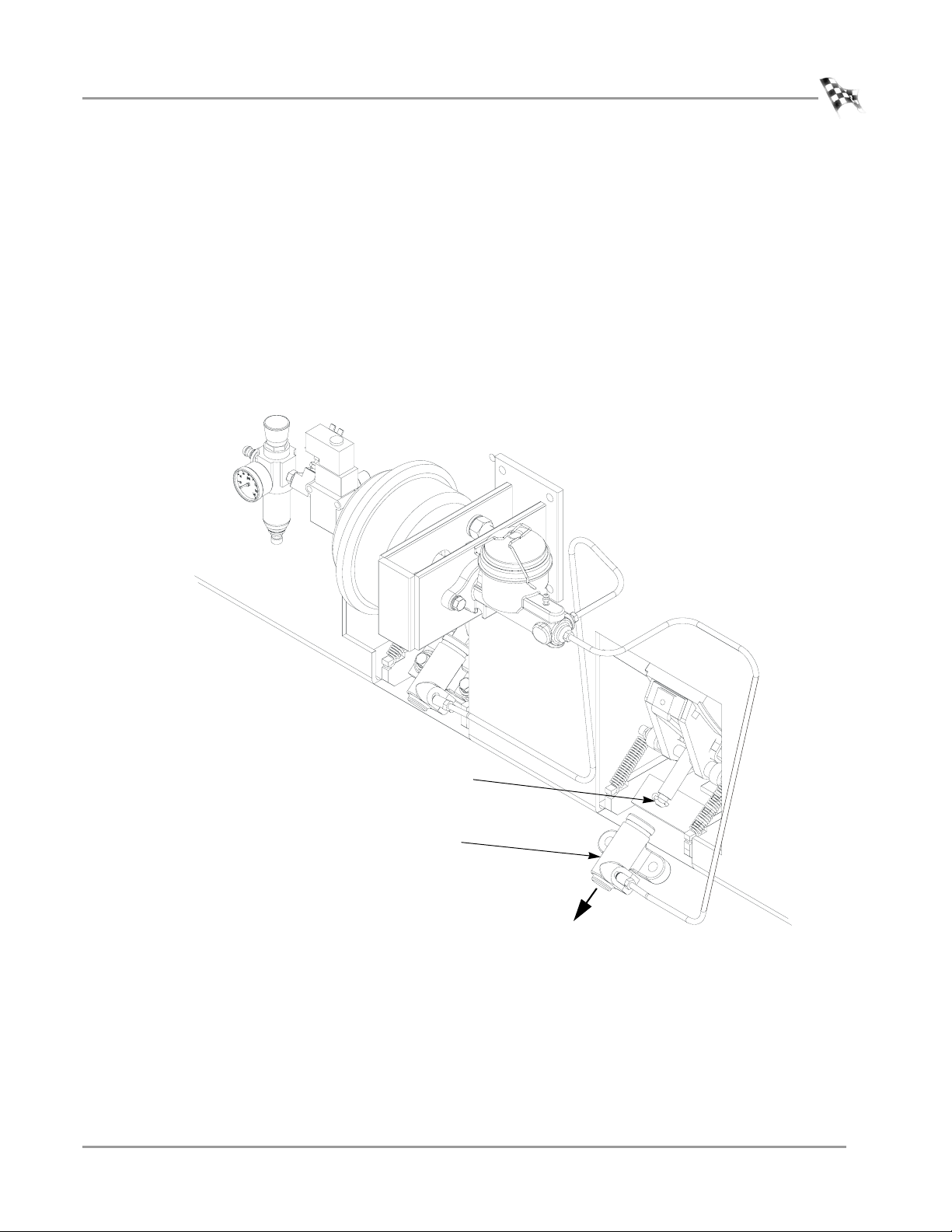
INSPECTING THE RAIL BRAKE CLEARANCE
Inspect the rail brake clearance once per month.
1 Shut off or disconnect the air supply to dyno, and follow your company’s lock out
procedure.
2 Press the red button on the pendant to activate the drum brakes; the button will
be lit.
3 Press and hold the dyno movement switch in either the in or out position until
you cannot hear any air going through the movement motor.
4 Using the red button on the pendant, cycle the drum brakes on and off several
times until no air is heard.
5 Remove the covers as necessary to provide safe working access to the dyno.
6 Using a ruler, measure the free play movement of each rail brake. The free play
should not exceed 3/16 inch (5mm).
7 If the rail brake free play is out of specification, adjust by loosening the jam nut
and turning the adjusting bolt until free play is within specification. Tighten the
jam nut while holding the adjusting bolt.
AUTO DYNO MAINTENANCE
4WD Attachment for Model 224 Dynos
Figure 17: 224 4WD Attachment—Inspect the Rail Brake Clearance
Version 3 Maintenance Guide for Automotive Dynamometers
19
Page 24

AUTO DYNO MAINTENANCE
Model 424x All-Wheel Drive Dynos
MODEL 424X ALL-WHEEL DRIVE DYNOS
. . . . . . . . . . . . . . . . . . . . . . . . . . . . . . . . . . .
This section covers maintenance items for model 424x dynos.
THINGS TO CHECK
• Check all air fittings for leaks monthly. Correct any leaks found.
• Check the air motor lubricator once per month and fill as necessary. Refer to
“Filling the Air Motor Lubricator” on page 21 for more information.
• Once per month verify that the SAAR brake pressure gauge reads 100psi
(690kPa). Adjust the regulator if the pressure is out of specification. Refer to
“Verifying the SAAR Brake Pressure” on page 23 for more information.
• Check the drum brake clearance. Refer to “Maintaining the SAAR Brake Shoe
Clearance” on page 24 for more information.
• Check the air can sleeve retraction. Refer to “Checking the Air Can Sleeve
Retraction” on page 26 for more information.
• Check customer supplied air filter/dryer daily, empty and clean as necessary.
• Inspect the 4WD dyno movement rails for debris once per month. Clear any debris
from the rails.
•Dyno Bearing Grease:
Under steady use, over 25 runs per day, each bearing should receive .65oz (19 ml)
of a recommended grease every 2 months.
Under occasional use, less than 25 runs per day, each bearing should receive
.65oz (19 ml) of a recommended grease every six months.
Recommended Grease:
grease specification description
thickener Lithium 12 Hydroxy Stearate
oil Petroleum
thickness NLGI 2
operating temperature
(Fahrenheit)
operating temperature
(Celsius)
EP additive yes
20
Maintenance Guide for Automotive Dynamometers
examples Mobil Mobilith AW-2
-20°F to 200°F, intermittent to 250°F
-29°C to 93°C, intermittent to 121°C
Page 25

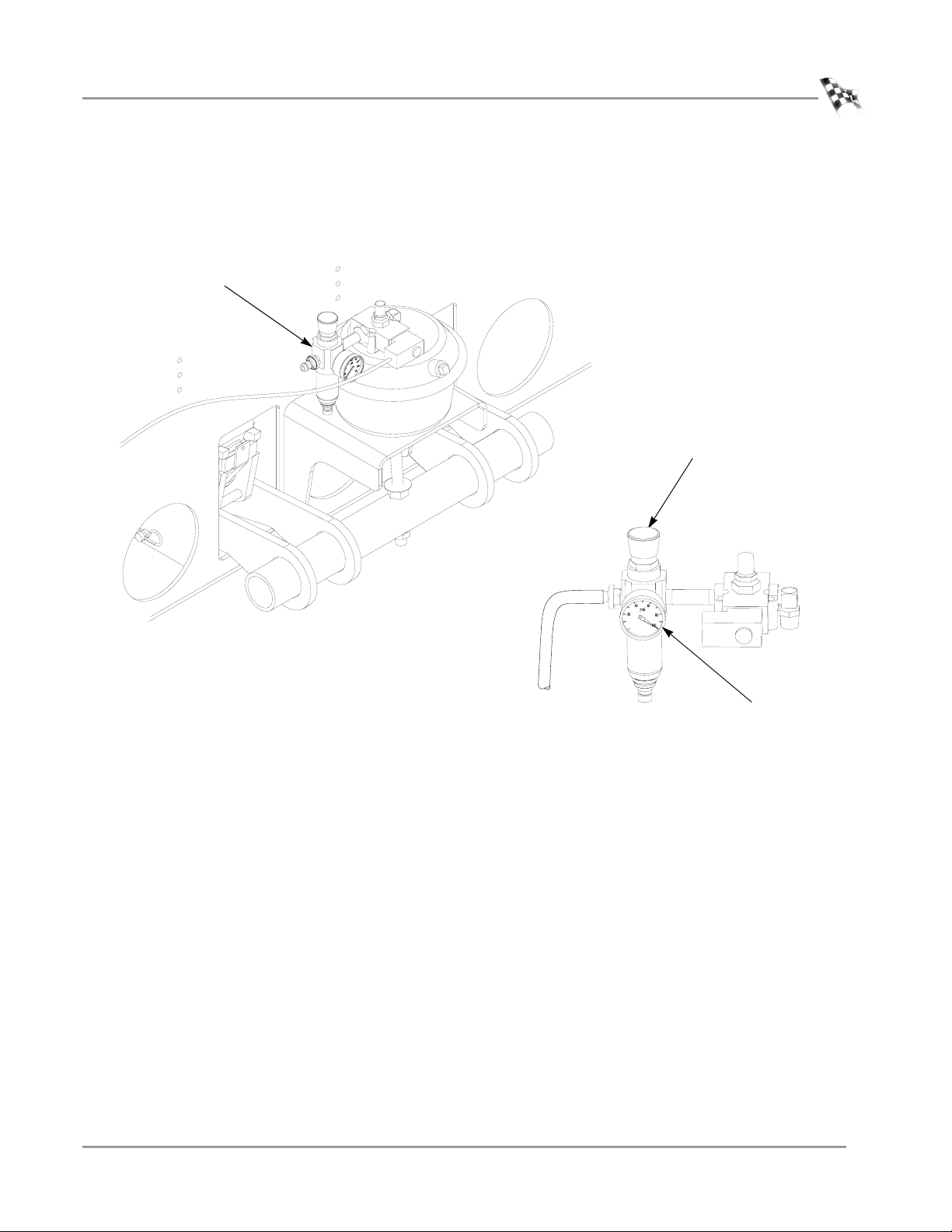
FILLING THE AIR MOTOR LUBRICATOR
Check the air motor lubricator once per month and fill as necessary.
1 Disconnect the air before removing the lubricator bowl.
2 Shut off or disconnect the air supply to the dyno, and follow lock out procedure.
3 Press and hold the dyno in or out movement switch until you cannot hear any air
going through the movement motor.
4 Before running the Gast Air Motor, remove the lubricator bowl and fill the bowl
with oil.
Note: Use a non-detergent SAE #10 automotive engine oil (Gast Part #AD220).
remove bowl and
fill to line with oil
AUTO DYNO MAINTENANCE
Model 424x All-Wheel Drive Dynos
AD0195
Figure 18: 424x Dyno—Filling the Air Motor Lubricator
Version 3 Maintenance Guide for Automotive Dynamometers
21
Page 26

AUTO DYNO MAINTENANCE
Model 424x All-Wheel Drive Dynos
ADJUSTING THE AIR MOTOR LUBRICATOR
Use the following steps to adjust the amount of oil provided by the air motor
lubricator.
1 Turn the top knob on the air motor lubricator clockwise until it shuts off the flow
of oil.
2 Back off the knob one turn counter-clockwise to start the flow of oil.
3 Adjust the knob as needed between one turn and fully on (turning counter-
clockwise) as needed for the particular environment in your dyno room.
turn knob to adjust
amount of oil delivered
Figure 19: 424x Dyno—Adjusting the Air Motor Lubricator
22
Maintenance Guide for Automotive Dynamometers
AD0195
Page 27

VERIFYING THE SAAR BRAKE PRESSURE
1 Verify the SAAR brake pressure gauge reads 100psi (690kPa).
2 Using the knob, adjust the regulator until the correct pressure is achieved.
brake pressure
regulator
AUTO DYNO MAINTENANCE
Model 424x All-Wheel Drive Dynos
AB096
use knob to adjust
regulator until correct
pressure is achieved
0
brake pressure gauge
should read 100psi
Figure 20: 424x Dyno—Check the SAAR Brake Pressure and Adjust the Regulator
AB095
(690kPA)
Version 3 Maintenance Guide for Automotive Dynamometers
23
Page 28

AUTO DYNO MAINTENANCE
Model 424x All-Wheel Drive Dynos
MAINTAINING THE SAAR BRAKE SHOE CLEARANCE
1 Verify the area is clear and the dyno can be operated safely.
2 Power up the dyno electronics.
3 Using the pendant, turn the brake to the off position. This will release the SAAR
brake by moving the brake shoe away from the drum.
Keep hands and fingers clear when operating dyno.
4 Measure the gap between the brake shoe and the drum surface. This gap should
be between .125 inch - .375 inch (3mm - 10mm).
Note: For clarity, the dyno frame is shown transparently to reveal the drum.
Note: The mounting bracket shown is used with the SAAR upgrade. Factory
installed SAAR brakes use a slightly different bracket.
brake shoe
drum
measure gap
AB094
Figure 21: 424x SAAR Brake—Measure the Gap Between the Brake Shoe and Drum
24
Maintenance Guide for Automotive Dynamometers
Page 29

AUTO DYNO MAINTENANCE
Model 424x All-Wheel Drive Dynos
5 If the brake shoe clearance is out of specification, loosen the upper nut on the air
can rod.
6 Adjust the lower nut until the brake shoes are .25 inch (6mm) away from the dyno
drum.
7 Tighten the upper nut on the air can rod down onto the brake actuating tube to
sandwich the tube between the two nuts.
8 Torque the lower nut to 110 foot-pounds.
If you cannot adjust the brakes to specification, you will need new brake shoes.
Contact Dynojet.
air can rod
upper nut
brake actuating tube
BR032
lower nut
Figure 22: 424x SAAR Brake—Adjust the Brake Shoe Clearance
CHANGING THE SAAR BRAKE SHOES
Refer to “Changing the SAAR Brake Shoes” on page 10 for detailed instructions.
Version 3 Maintenance Guide for Automotive Dynamometers
25
Page 30

AUTO DYNO MAINTENANCE
Model 424x All-Wheel Drive Dynos
CHECKING THE AIR CAN SLEEVE RETRACTION
The SAAR brake’s air can sleeve must be positioned correctly for safe operation.
If the air can sleeve is not in the correct location, use a wrench and loosen the nut as
far as you can. The sleeve will drop down as shown in Figure 23. Check all four air
cans.
Note: Verify that the brakes are operating properly before replacing the covers
and using the dyno.
sleeve
nut
correct placement of
nut and sleeve
incorrect placement of
nut and sleeve
sleeve
nut
26
Maintenance Guide for Automotive Dynamometers
AD0194
Figure 23: 424x Dyno—Air Can Sleeve
Page 31

AUTO DYNO MAINTENANCE
MODEL 248 DYNOS
. . . . . . . . . . . . . . . . . . . . . . . . . . . . . . . . . . .
This section covers maintenance items for model 248 dynos.
THINGS TO CHECK
• Check all air fittings for leaks monthly. Correct any leaks found.
• Once per month verify the drum brake pressure gauge is reading 55 to 65psi
(450kPa). Adjust the regulator if the pressure is out of specification.
• Maintain the brake shoe clearance. Refer to “Checking the 248 Drum Brake Shoe
Clearance” on page 28 for more information.
•Dyno Bearing Grease:
Under steady use, over 25 runs per day, each bearing should receive 1.5oz
(44.36 ml) of a recommended grease every 2 months.
Under occasional use, less than 25 runs per day, each bearing should receive
1.5oz (44.36 ml) of a recommended grease every six months.
Recommended Grease:
Model 248 Dynos
grease specification description
thickener Lithium Complex
oil Petroleum
thickness NLGI 2
operating temperature
(Fahrenheit)
operating temperature
(Celsius)
examples Mobil Mobilith AW-2
-20°F to 200°F, intermittent to 250°F
-29°C to 93°C, intermittent to 121°C
Version 3 Maintenance Guide for Automotive Dynamometers
27
Page 32

AUTO DYNO MAINTENANCE
Model 248 Dynos
CHECKING THE 248 DRUM BRAKE SHOE CLEARANCE
The 248 drum brake shoe clearance needs to be checked once per month. Use the
following steps.
1 Remove the air from the system.
1a Shut off or disconnect the air supply to the dyno, and follow lock out
procedure.
1b Press the red button on the pendant to activate the drum brakes; the button
will be lit.
1c Press and hold the dyno in or out movement switch until you cannot hear
any air going through the movement motor.
Note: If there is no 4WD dyno, skip this step.
1d Using the red button on the pendant, cycle the drum brakes on and off
several times until no air is heard.
2 Remove the covers as necessary to provide safe working access to the dyno.
3 Measure the gap between the brake shoe and the drum surface. This gap should
be .125 inch - .50 inch (3mm - 13mm).
28
Maintenance Guide for Automotive Dynamometers
Page 33

AUTO DYNO MAINTENANCE
Model 248 Dynos
4 If the brake shoe clearance is out of specification perform the following steps:
4a Remove the cotter key from the clevis pin and remove clevis pin.
4b Remove the two 5/8-inch nuts and washers securing the air can to the brake
bracket.
4c Loosen the jam nut.
4d Pull the air can up so that the clevis can be turned. Screwing the clevis down
the air can rod will decrease brake shoe clearance.
4e With the clevis adjusted, secure the jam nut.
4f Place the air can on brake bracket and secure with nuts and washers
removed earlier.
4g Secure clevis with pin and cotter key.
4h Adjust the brake shoe support so that the brake shoe clearance is even over
the length of the shoe.
• Loosen the jam nut and turn the brake shoe support.
• With the brake shoe support adjusted, tighten the jam nut.
If you cannot adjust the brakes to specification, you will need new brake shoes.
Contact Dynojet.
5 Turn on or reconnect the air supply and check that the drum brakes operate
before replacing the covers and using the dyno.
Figure 24: 248 Dyno—Remove Cotter Key
Version 3 Maintenance Guide for Automotive Dynamometers
29
Page 34

Page 35

 Loading...