

Page 1
Page 2

©1993-2005 Dynojet Research, Inc. All Rights Reserved.
Installation Guide For In Ground Model 224 Automotive Dynamometers
With Four Wheel Drive Attachment.
This manual is copyrighted by Dynojet Research, Inc., hereafter referred to as Dynojet,
and all rights are reserved. This manual, and the software described in it, is furnished
under license and may only be used or copied in accordance with the terms of such
license. This manual is furnished for informational use only, is subject to change without
notice, and should not be construed as a commitment by Dynojet. Dynojet assumes no
responsibility or liability for any error or inaccuracies that may appear in this manual.
Except as permitted by such license, no part of this manual may be reproduced, stored in
a retrieval system, or transmitted, in any form or by any means, electronic, mechanical,
recording, or otherwise, without the prior written permission of Dynojet.
The Dynojet logo is a trademark of Dynojet Research, Inc.
Any trademarks, trade names, service marks, or service names owned or registered by any
other company and used in this guide are the property of their respective companies.
Dynojet Research, Inc., 2191 Mendenhall Drive, North Las Vegas, Nevada 89081, USA.
Printed in USA.
Part Number: 98210104 Version 3 (08/05)
RECORD
Dynamometer Number: ____________________________________________________
#
Page 3

T
ABLE OF
C
ONTENTS
Warnings . . . . . . . . . . . . . . . . . . . . . . . . . . . . . . . . . . . . . . . . . . . . . . . . v
Chapter 1 Specifications and Operating Requirements
Introduction . . . . . . . . . . . . . . . . . . . . . . . . . . . . . . . . . . . . . . . . . . . . . . . . . .1-2
Conventions Used In This Manual . . . . . . . . . . . . . . . . . . . . . . . . . . . . . . .1-3
Technical Support . . . . . . . . . . . . . . . . . . . . . . . . . . . . . . . . . . . . . . . . . . .1-3
Dynamometer Specifications and Requirements . . . . . . . . . . . . . . . . . . . .1-4
Chassis Specifications . . . . . . . . . . . . . . . . . . . . . . . . . . . . . . . . . . . . . . . . .1-4
Compressed Air . . . . . . . . . . . . . . . . . . . . . . . . . . . . . . . . . . . . . . . . . . . . .1-6
Computer Specifications . . . . . . . . . . . . . . . . . . . . . . . . . . . . . . . . . . . . . .1-6
Electrical Requirements . . . . . . . . . . . . . . . . . . . . . . . . . . . . . . . . . . . . . . .1-6
Environmental Requirements . . . . . . . . . . . . . . . . . . . . . . . . . . . . . . . . . . .1-7
Fire Suppression . . . . . . . . . . . . . . . . . . . . . . . . . . . . . . . . . . . . . . . . . . . . .1-7
Forklift Requirements . . . . . . . . . . . . . . . . . . . . . . . . . . . . . . . . . . . . . . . . . 1-7
Ground Hooks . . . . . . . . . . . . . . . . . . . . . . . . . . . . . . . . . . . . . . . . . . . . . .1-7
Phone and Internet Access . . . . . . . . . . . . . . . . . . . . . . . . . . . . . . . . . . . . .1-7
Tie-Down Straps . . . . . . . . . . . . . . . . . . . . . . . . . . . . . . . . . . . . . . . . . . . .1-7
Model 224 4WD Dynamometer . . . . . . . . . . . . . . . . . . . . . . . . . . . . . . . . .1-8
Model 224 4WD Dynamometer With Grates . . . . . . . . . . . . . . . . . . . . . . .1-9
Pit Specifications For 224 With 4WD Attachment . . . . . . . . . . . . . . . . . .1-10
In Ground Model 224 4WD Automotive Dynamometer Installation Guide
i
Page 4

TABLE OF CONTENTS
Chapter 2 Installation
Unpacking and Inspecting the Dyno . . . . . . . . . . . . . . . . . . . . . . . . . . . . . .2-2
Track Assembly . . . . . . . . . . . . . . . . . . . . . . . . . . . . . . . . . . . . . . . . . . . . . . .2-3
Installing the Track Assembly . . . . . . . . . . . . . . . . . . . . . . . . . . . . . . . . . . .2-5
Dyno Installation . . . . . . . . . . . . . . . . . . . . . . . . . . . . . . . . . . . . . . . . . . . . . .2-7
Removing the Dyno from the Crate . . . . . . . . . . . . . . . . . . . . . . . . . . . . . .2-7
Placing the Dyno in the Pit . . . . . . . . . . . . . . . . . . . . . . . . . . . . . . . . . . . .2-9
Routing Cables . . . . . . . . . . . . . . . . . . . . . . . . . . . . . . . . . . . . . . . . . . . . . .2-11
Identifying the Cables . . . . . . . . . . . . . . . . . . . . . . . . . . . . . . . . . . . . . . .2-11
Routing the Cables . . . . . . . . . . . . . . . . . . . . . . . . . . . . . . . . . . . . . . . . .2-13
Routing Cables—224xLC . . . . . . . . . . . . . . . . . . . . . . . . . . . . . . . . . . . . . .2-18
Chain Installation . . . . . . . . . . . . . . . . . . . . . . . . . . . . . . . . . . . . . . . . . . . .2-20
4WD Dyno Movement Test . . . . . . . . . . . . . . . . . . . . . . . . . . . . . . . . . . . .2-22
Grate Placement and Installation . . . . . . . . . . . . . . . . . . . . . . . . . . . . . . . .2-23
Installing the New 248 Pit Covers . . . . . . . . . . . . . . . . . . . . . . . . . . . . . .2-23
Installing the Cross Brace Assemblies . . . . . . . . . . . . . . . . . . . . . . . . . . . .2-24
Installing the Center Grates and Center Plate . . . . . . . . . . . . . . . . . . . . . .2-26
Installing the Side Grates . . . . . . . . . . . . . . . . . . . . . . . . . . . . . . . . . . . . .2-27
Installing the Drum Guards . . . . . . . . . . . . . . . . . . . . . . . . . . . . . . . . . . .2-28
Chapter 3 Dyno Electronics
Dyno Electronics . . . . . . . . . . . . . . . . . . . . . . . . . . . . . . . . . . . . . . . . . . . . . .3-2
Atmospheric Sensing Module . . . . . . . . . . . . . . . . . . . . . . . . . . . . . . . . . .3-2
RPM Module . . . . . . . . . . . . . . . . . . . . . . . . . . . . . . . . . . . . . . . . . . . . . . . 3-3
Dynamometer Input/Output Module . . . . . . . . . . . . . . . . . . . . . . . . . . . . .3-4
CPU Module . . . . . . . . . . . . . . . . . . . . . . . . . . . . . . . . . . . . . . . . . . . . . . .3-5
Chapter 4 Basic Dyno Operation
Loading the Car . . . . . . . . . . . . . . . . . . . . . . . . . . . . . . . . . . . . . . . . . . . . . . . 4-2
Connecting the RPM Pickup . . . . . . . . . . . . . . . . . . . . . . . . . . . . . . . . . . . .4-5
RPM Pickup Descriptions . . . . . . . . . . . . . . . . . . . . . . . . . . . . . . . . . . . . . .4-5
Connecting the Secondary Inductive Pickup . . . . . . . . . . . . . . . . . . . . . . .4-6
Connecting the Primary Inductive Pickup . . . . . . . . . . . . . . . . . . . . . . . . . 4-7
Pre-run Inspection . . . . . . . . . . . . . . . . . . . . . . . . . . . . . . . . . . . . . . . . . . . . .4-8
Before Starting the Engine . . . . . . . . . . . . . . . . . . . . . . . . . . . . . . . . . . . . .4-8
Engine Warm Up . . . . . . . . . . . . . . . . . . . . . . . . . . . . . . . . . . . . . . . . . . . .4-9
After Engine Warm Up . . . . . . . . . . . . . . . . . . . . . . . . . . . . . . . . . . . . . . . .4-9
Making a Test Run . . . . . . . . . . . . . . . . . . . . . . . . . . . . . . . . . . . . . . . . . . .4-10
Preventative Maintenance . . . . . . . . . . . . . . . . . . . . . . . . . . . . . . . . . . . . .4-11
Model 224 and 224 4WD Dynos—Things to Check . . . . . . . . . . . . . . . . . 4-11
Model 224 Dynos with 4WD Attachment—Things to Check . . . . . . . . . . 4-12
Checking the 224 Drum Brake Shoe Clearance . . . . . . . . . . . . . . . . . . . .4-13
Model 224 4WD—Inspecting the Rail Brake Clearance . . . . . . . . . . . . . .4-15
ii
In Ground Model 224 4WD Automotive Dynamometer Installation Guide
Page 5

Appendix A Red Head Anchor Installation
Installation . . . . . . . . . . . . . . . . . . . . . . . . . . . . . . . . . . . . . . . . . . . . . . . . . . .A-2
Index . . . . . . . . . . . . . . . . . . . . . . . . . . . . . . . . . . . . . . . . . . . . . . . . . . . Index-i
TAB LE OF CONT ENTS
Version 3 In Ground Model 224 4WD Automotive Dynamometer Installation Guide
iii
Page 6

Page 7

W
ARNINGS
Disclaimers
Dynojet Research, Inc. (Dynojet) makes no representation or warranties with respect to the contents
hereof and specifically disclaims any implied warranties of merchantability for any particular purpose.
Dynojet reserves the right to revise this publication and to make changes from time to time in the
content hereof without obligation of Dynojet to notify any person of such revision or changes.
Dynojet is not responsible for false operation due to unexpected dynamometer operation such as may
be caused by static, software bugs, hardware failure, etc.
Dynojet is not responsible for damage resulting from improper installation of the dynamometer or
from improper service rendered to the dynamometer. Dynojet is not responsible for damage incurred
due to alteration of the dynamometer or components, use of unapproved parts, or abuse to the
dynamometer.
Do not connect or disconnect cables or components on the dynamometer with the power on.
Always wear protective clothing, ear protection, and eye protection (goggles, safety glasses) when
using and servicing the dynamometer.
Equipment Power Requirements
The dynamometer has specific power requirements. Connecting the dynamometer to the incorrect
voltage will void the dynamometer warranty. Installation may require a licensed electrician.
Potentially Lethal Voltages
Components attached to and within the dynamometer operate with potentially lethal voltages. To
provide the greatest assurance of safety, the AC power cord(s) must be disconnected from the power
source before servicing electrical components or wiring. Disconnect all power cords before servicing
electrical components for the greatest assurance of safety.
In Ground Model 224 4WD Automotive Dynamometer Installation Guide
v
Page 8

WARN INGS
Electrostatic Discharge Precautions
Electrostatic Discharge
Electrostatic Discharge (ESD), or static shock, can damage electronic components within the
dynamometer. The damage may occur at the time of an ESD occurrence, or the shock may degrade
the component, resulting in a premature component failure later. To avoid ESD damage, always
practice good ESD control precautions when servicing the dynamometer. Dynojet designs its
dyn amo me ter s t o be ver y t ole ran t o f st ati c sh oc ks by the users, but the electronics are vulnerable when
the electronics are exposed. ESD occurs as a result of a difference of potential between two objects
when the two objects touch. Damage occurs as a result of the energy released when the discharge
(touch) occurs. The difference of potential can accumulate by as simple an action as a user moving
across carpet or a seat. If that person’s energy is discharged directly to the electronics, the electronics
can be damaged.
Precautions
To protect against ESD damage, you must eliminate the difference of potential before the electronics
are handled. Touch the chassis of the dynamometer before touching any of the electronics. By touching
the chassis, you discharge any static shocks to the chassis instead of to the electronics.
If you are holding a circuit board or dynamometer component in your hand when you approach the
machine, touch the chassis of the dynamometer with your hand before installing the circuit board or
component.
When handling a circuit board or component to someone, touch that person with your hand first,
then hand them the component.
Always carry circuit boards in anti-static bags when the boards are exposed (removed from the
dynamometer).
Battery Fire and Explosion Hazards
There is a danger of explosion if the battery is incorrectly replaced. Replace only with the same or
equivalent type recommended by the manufacturer. Discard used batteries according to the
manufacturer’s instructions.
Automotive Batteries
In operation, batteries generate and release flammable hydrogen gas. They must always be assumed
to contain this gas which, if ignited by burning cigarette, naked flame or spark, may cause battery
explosion with dispersion of casing fragments and corrosive liquid electrolyte. Carefully follow
manufacturer's instructions for installation and service. Keep away all sources of gas ignition and do
not allow metallic articles to simultaneously contact the negative and positive terminals of a battery.
Do not allow the positive and negative terminals to short-circuit. The dynamometer chassis is tied to
the negative side of the battery. Do not short between the positive battery terminal or the starter
connections to the chassis. In addition, make sure metal tools such as screw drivers, wrenches, and
torque wrenches do not come in contact with the negative and positive terminals of the battery. Short
circuiting the terminals of the battery can cause burn injuries, damage to the dynamometer, or trigger
explosions.
Charging
Batteries being charged will generate and release flammable hydrogen gas. Charging space should be
ventilated. Keep battery vent caps in position. Prohibit smoking and avoid creation of flames and sparks
nearby.
Wear protective clothing, eye and face protection, when charging or handling batteries.
vi
In Ground Model 224 4WD Automotive Dynamometer Installation Guide
Page 9

WARNINGS
Other Potential Hazards
The AC power outlet shall be installed near the equipment and it shall be easily accessible to allow for
disconnect before service.
The dynamometer should be located in a well ventilated area. There is a carbon monoxide hazard with
all internal combustion engines. Engine exhaust contains poisonous carbon monoxide gas. Breathing
it could cause death.
Always wear proper ear and eye protection when operating the dynamometer.
Never operate the dynamometer with the covers removed.
Never stand behind the dynamometer when in operation.
Never operate the dynamometer when there is excessive vibration or noise. Resolve these problems
before proceeding.
Verify brake operation before beginning any dynamometer testing.
Verify the vehicle is properly secured to the dynamometer.
Never operate the blowers without the guards installed.
Exercise care with any dynamometer testing; portions of the dynamometer and vehicle may become
hot.
As with any equipment using electricity and having moving parts, there are potential hazards. To use
this dynamometer safely, the operator should become familiar with the instructions for operation of
the dynamometer and always exercise care when using it.
Do not repair or replace any part of the dynamometer or attempt any servicing unless specifically
recommended in published user-repair instructions that you understand and have the skills to carry
out.
Version 3 In Ground Model 224 4WD Automotive Dynamometer Installation Guide
vii
Page 10

Page 11

C HAPTER
S
PECIFICATIONS AND
Thank you for purchasing Dynojet’s In Ground Model 224 Automotive Dynamometer
(dyno) with Four Wheel Drive (4WD) Attachment. Dynojet’s software and
dynamometers will give you the power to get the maximum performance out of
vehicles you evaluate. Whether you are new to the benefits of a chassis dynamometer
or an experienced performance leader, the repeatability and diagnostic tools of
WinPEP 7 software and a Dynojet dynamometer will give you the professional results
you are looking for.
This document provides instructions for installing the 224 4WD dyno. This document
will walk you through operating requirements, hardware installation, electronics set
up, and basic dyno operation. To ensure safety and accuracy in the procedures,
perform the procedures as they are described.
Document Part Number: 98210104
O
PERATING
R
EQUIREMENTS
1
Versio n 3
Last Updated: 08-15-05
This chapter is divided into the following categories:
•Introduction, page 1-2
• Dynamometer Specifications and Requirements, page 1-4
• Model 224 4WD Pit Dynamometer, page 1-8
• Model 224 4WD Pit Dynamometer with Grates, page 1-9
• Pit Specifications, page 1-10
In Ground Model 224 4WD Automotive Dynamometer Installation Guide
1-1
Page 12

CHAPTER 1
Introduction
INTRODUCTION
. . . . . . . . . . . . . . . . . . . . . . . . . . . . . . . . . . .
Thank you for purchasing a Dynojet automotive dyno. Before installing your dyno,
please take a moment to read this guide for installation instructions, dyno features,
and other important information.
This guide is designed to be a reference tool in your everyday work and includes the
following chapters and information:
SPECIFICATIONS AND OPERATING REQUIREMENTS
This chapter describes the requirements and specifications for the dyno.
INSTALLATION
This chapter describes the procedures for installing the dyno.
ELECTRONICS
This chapter describes the specifications for the dyno electronics.
BASIC DYNO OPERATION
This chapter describes basic dyno operating procedures and maintenance.
RED HEAD INSTALLATION
This appendix describes the procedures for installing the Red Head anchors.
1-2
In Ground Model 224 4WD Automotive Dynamometer Installation Guide
Page 13
SPECIFICATIONS AND OPERATING REQUIREMENTS
CONVENTIONS USED IN THIS MANUAL
The conventions used in this manual are designed to protect both the user and the
equipment.
example of convention description
The Caution icon indicates a potential hazard to the
dynamometer equipment. Follow all procedures
exactly as they are described and use care when
performing all procedures.
The Warning icon indicates potential harm to the
person performing a procedure and/or the
dynamometer equipment.
The Record # icon reminds you to record your
RECORD
#
dynamometer and/or eddy current brake (retarder)
number on the inside cover of this manual.
Introduction
Bold
TECHNICAL SUPPORT
For assistance, please contact Dynojet Technical Support at 1-800-992-3525, or write
to Dynojet at 2191 Mendenhall Drive, North Las Vegas, NV 89081.
Visit us on the World Wide Web at www.dynojet.com where Dynojet provides state of
the art technical support, on-line shopping, 3D visualizations, and press releases
about our latest product lines.
Highlights items you can select on in the software
interface, including buttons and menus.
The arrow indicates a menu choice. For example,
“select
File Open” means “select the File menu,
then select the
Open choice on the File menu.”
Version 3 In Ground Model 224 4WD Automotive Dynamometer Installation Guide
1-3
Page 14

CHAPTER 1
Dynamometer Specifications and Requirements
DYNAMOMETER SPECIFICATIONS AND REQUIREMENTS
. . . . . . . . . . . . . . . . . . . . . . . . . . . . . . . . . . .
The following specifications and requirements will help you set up your dyno area
and verify you have the requirements necessary to operate your dyno safely.
CHASSIS SPECIFICATIONS
description specifications
Length
of frame 218.44 cm (86.00 in.)
Height
to top of frame 58.42 cm (23.00 in.)
Width
of frame 73.66 cm (29.00 in.)
including cradle assembly 111.89 cm (44.05 in.)
including brake 96.52 cm (38.00 in.)
Track Assembl y
Length 208.92 cm (82.25 in.)
Width 218.44 cm (86.00 in.)
Weight
224 dyno/crated dyno 1588 kg (3500 pounds)/ 1905.09 kg (4200 pounds)
Drum
diameter 60.96 cm (24.00 in.)
width 243.84 cm (96.00 in.)
Frame structural steel channel and angle
Maximum Horsepower 745.58 KW (1000 HP)
Maximum Speed 289.68 KPH (180 MPH)
Maximum Axle Weight 1361 kg (3000 pounds)
Remote Switches remote software control
1-4
In Ground Model 224 4WD Automotive Dynamometer Installation Guide
Page 15
SPECIFICATIONS AND OPERATING REQUIREMENTS
Dynamometer Specifications and Requirements
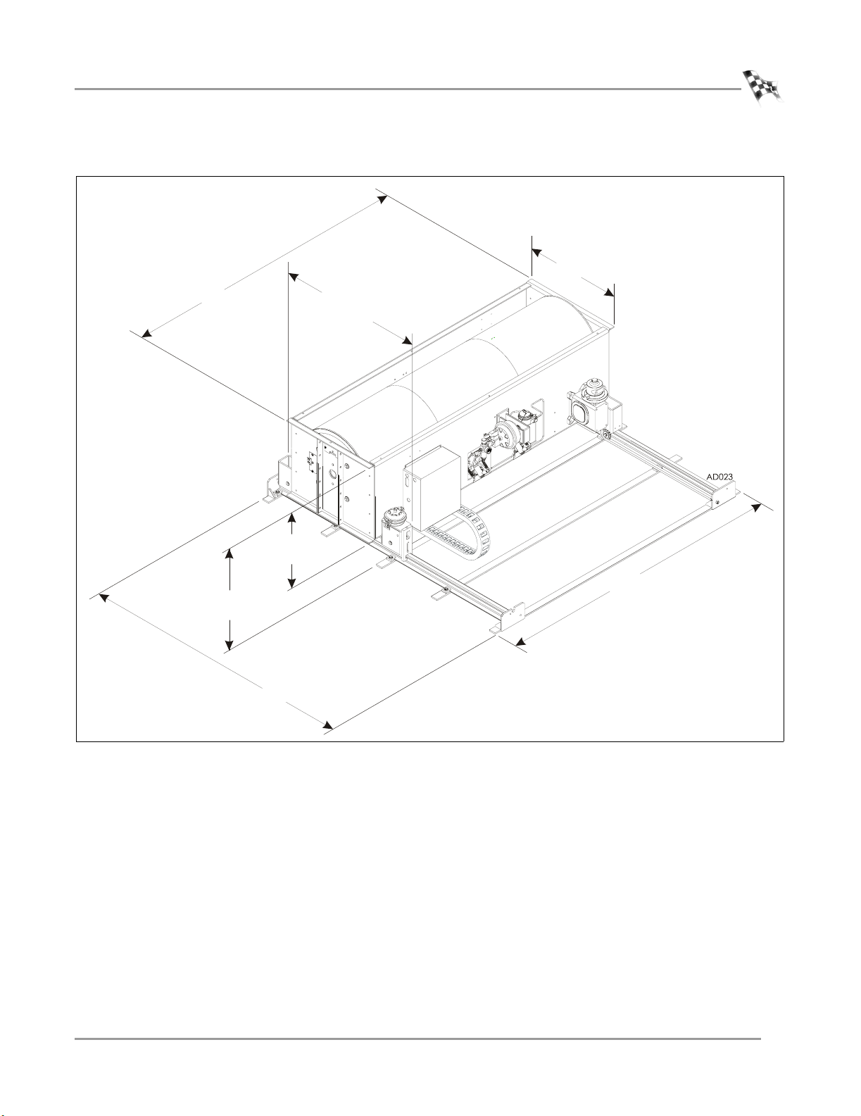
73.66 cm (29.00 in.)
218.44 cm (86.00 in.)
72.07 cm (28.375 in.)
frame to floor
208.92 cm (82.25 in.)
111.89 cm (44.05 in.)
frame and cradle assembly
58.42 cm
(23.00 in.)
218.44 cm (86.00 in.)
Figure 1-1: Model 224 4WD with Track Assembly Dimensions
Version 3 In Ground Model 224 4WD Automotive Dynamometer Installation Guide
1-5
Page 16

CHAPTER 1
Dynamometer Specifications and Requirements
COMPRESSED AIR
The following requirements are needed for the air brake:
• Clean and dry air, at least 100 psi
• shut off valve
• 1/4-inch NPT pipe thread connector (to attach air to the dyno), if air hose does not
have a 3/8-inch inside diameter
COMPUTER SPECIFICATIONS
You will need to provide a computer system to run the WinPEP software. WinPEP 7
includes complete documentation in online Help. From the WinPEP 7 menu bar,
choose Help
minimum system requirements recommended systems requirements
• Microsoft® Windows 2000/XP • Microsoft® Windows 2000/XP
• Pentium 800 MHz Processor • 2.4 GHz Processor or greater
• 256 MB of available RAM • 256 MB of available RAM or greater
WinPEP 7 Help or visit www.winpep.com.
• one COM port, at least one extra USB port • one COM port, at least one extra USB port
• 800x600, 256 color monitor (SVGA) • 1280x1024 256 color monitor (SVGA) or better
• 1.2 gigabyte hard drive • 1.2 gigabyte hard drive
• 30 MB of available hard-disk space • 100 MB of available hard-disk space
• CD ROM and floppy disk drive • CD ROM and floppy disk drive
• printer, if hard copies are needed • printer (preferably HP DeskJet®)
description specifications
Power Requirements 110v or 240v outlet
Frequency 50 or 60 Hz
Current: computer, optional air pump 120v 15 amp (combined load should be less than 10A)
Power Requirements: optional eddy
current brake
ELECTRICAL REQUIREMENTS
240v 30amp single phase circuit
refer to the Eddy Current Brake Installation and User
Guide for Model 224 Pit Automotive Dynamometers
(P/N 98215101)
1-6
In Ground Model 224 4WD Automotive Dynamometer Installation Guide
Page 17

SPECIFICATIONS AND OPERATING REQUIREMENTS
Dynamometer Specifications and Requirements
ENVIRONMENTAL REQUIREMENTS
description specifications
Te mp e r at u r e
operating min./max 10°C/50°C (50°F/122°F)
storage min./max 0°C/70°C (32°F/158°F)
Humidity 0 to 95% non condensing
FIRE SUPPRESSION
Always have adequate fire suppression or fire extinguishers in your dyno room.
FORKLIFT REQUIREMENTS
You will need to provide equipment capable of lifting 1905 kg (4200 pounds) to lift
the crated dyno and 1588 kg (3500 pounds) to lift the dyno off the crate and into
position in your dyno room. You will also need a pair of straps capable of supporting
1588 kg (3500 pounds) to attach to the dyno. Dynojet recommends using single loop
style straps.
GROUND HOOKS
The ground hooks allow you to secure your car in place using the tie-down straps.
The layout of the ground hooks is described in the pit dimensions (P/N 98219105)
provided by your salesperson. Refer to Appendix A for Red Head Anchor installation
instructions.
PHONE AND INTERNET ACCESS
Dynojet recommends you have a phone close to the dyno to call for assistance in an
emergency. You may also wish to contact Dynojet to troubleshoot your dyno.
Internet access on your computer is desirable for contacting Dynojet and
downloading new information and updates.
TIE-DOWN STRAPS
Dynojet recommends using tie-down straps for securing the car on the dyno. The 224
dyno comes with an automotive tie-down package.
Version 3 In Ground Model 224 4WD Automotive Dynamometer Installation Guide
1-7
Page 18
CHAPTER 1
Model 224 4WD Dynamometer
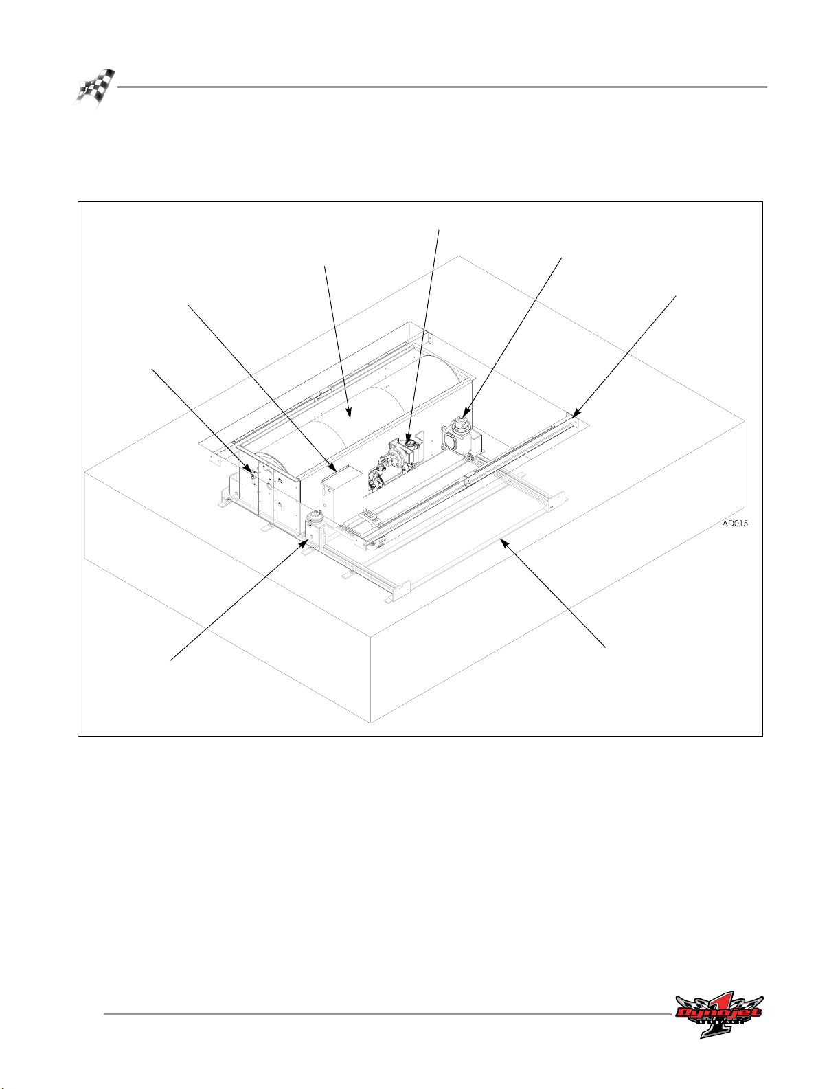
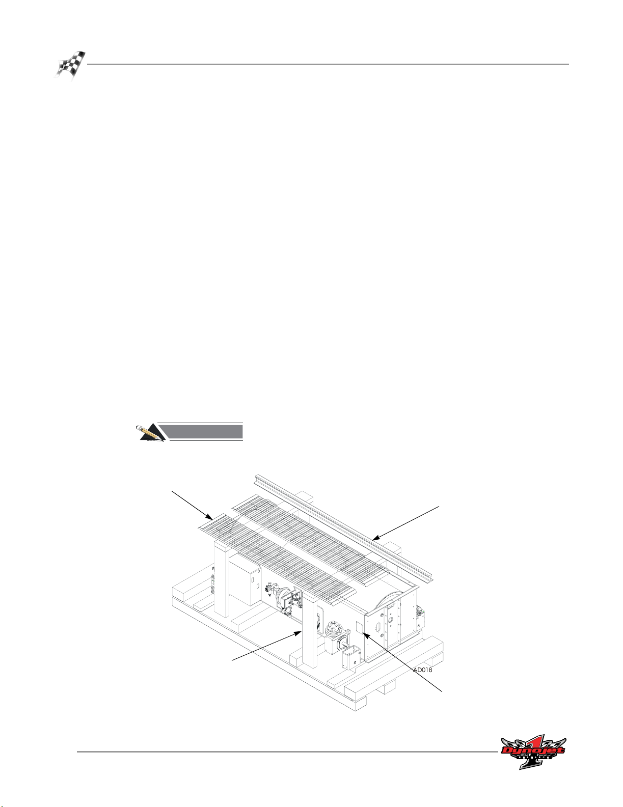
MODEL 224 4WD DYNAMOMETER
. . . . . . . . . . . . . . . . . . . . . . . . . . . . . . . . . . .
4WD Control Box
contains Breakout Board
and 4WD Movement Board
Pickup Card
Drum
precision balanced
and knurled
Air Brake
Dyno Movement
Motor
Cross Brace
Cradle Assembly
Figure 1-2: Model 224 4WD Dynamometer
1-8
In Ground Model 224 4WD Automotive Dynamometer Installation Guide
Track Assembly
Page 19
SPECIFICATIONS AND OPERATING REQUIREMENTS
Model 224 4WD Dynamometer With Grates
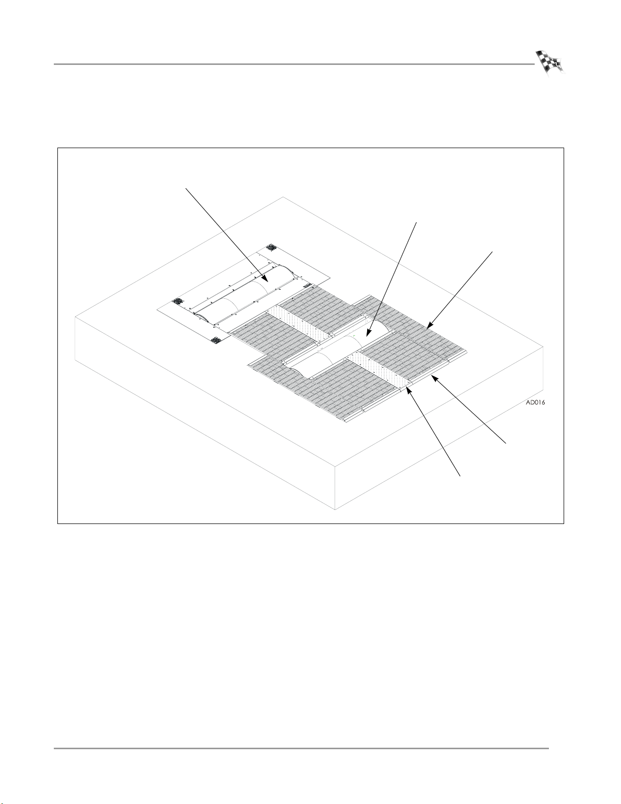
MODEL 224 4WD DYNAMOMETER WITH GRATES
. . . . . . . . . . . . . . . . . . . . . . . . . . . . . . . . . . .
Model 224
Stationary Dyno
Model 224 4WD
Dyno
Side Grate
Center Grate
Center Plate
Figure 1-3: Model 224 4WD Dynamometer with Grates
Version 3 In Ground Model 224 4WD Automotive Dynamometer Installation Guide
1-9
Page 20
CHAPTER 1
Pit Specifications For 224 With 4WD Attachment
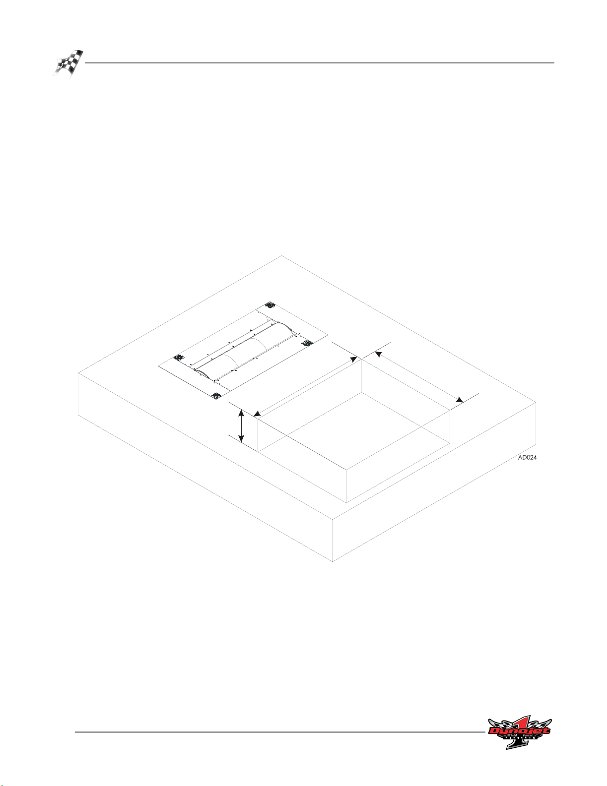
PIT SPECIFICATIONS FOR 224 WITH 4WD ATTACHMENT
. . . . . . . . . . . . . . . . . . . . . . . . . . . . . . . . . . .
Before placing the dyno in the pit, take a moment to verify the dimensions of the pit
are correct.
Refer to pit dimensions (P/N 98219105) you received from your salesman for more
detailed specifications.
• pit depth: 71.76 cm (28.25 in)
• pit length: 220.98 cm (87.00 in)
• pit width: 259.08 cm (102.00 in)
71.76 cm
(28.25 in)
259.08 cm
(102.00 in)
Figure 1-4: Verify Pit Dimensions
220.98 cm
(87.00 in)
1-10
In Ground Model 224 4WD Automotive Dynamometer Installation Guide
Page 21

C HAPTER
2
I
NSTALLATION
This chapter will walk you through unpacking and installing the dynamometer. To
ensure safety and accuracy in the procedures, perform the procedures as they are
described.
This chapter is divided into the following categories:
• Unpacking and Inspecting the Dyno, page 2-2
• Track Assembly, page 2-3
• Dyno Installation, page 2-7
• Routing Cables, page 2-11
• Routing Cables—224xLC, page 2-18
• Chain Installation, page 2-20
• 4WD Dyno Movement Test, page 2-22
• Grate Placement and Installation, page 2-23
In Ground Model 224 4WD Automotive Dynamometer Installation Guide
2-1
Page 22
CHAPTER 2
Unpacking and Inspecting the Dyno
UNPACKING AND INSPECTING THE DYNO
. . . . . . . . . . . . . . . . . . . . . . . . . . . . . . . . . . .
When you receive your dyno, examine the exterior of the shipping container for any
visible damage. If damage is detected at this stage, contact the shipper or Dynojet
before proceeding with unpacking.
Use the following steps to unload your dyno. You will need to provide equipment
capable of lifting a minimum of 1905 kg (4200 pounds) to move the crated dyno into
position in your dyno room. Refer to “Dynamometer Specifications and
Requirements” on page 1-4 for more information.
1 Move the crated dyno to a clear area near your dyno room.
2 Using a pry bar, or a large flat screwdriver, and a hammer, carefully remove the
top and sides of the crate.
Note: At this point, you will want to inspect the exterior of the dyno for any
indications of damage. Report any damage immediately.
3 Remove the grates, track assembly, and braces from the top portion of the crate
and set aside.
Note: For clarity, only two grates and one rail are shown in Figure 2-1.
4 Remove the parts and hardware boxes from the crate and set aside.
5 Remove the crate braces that supported the grates.
6 Before removing the dyno from the crate, you will need to install the track
assembly in your pit. Refer to the instructions page 2-3 for more information on
installing the track assembly.
(for clarity, not all
grates are shown)
RECORD
Be sure you record the dynamometer number on the inside cover of this
manual.
grates
crate brace
#
rail
(for clarity, not all parts to the
track assembly are shown)
dyno number
Figure 2-1: Unpacking the Dyno
2-2
In Ground Model 224 4WD Automotive Dynamometer Installation Guide
Page 23

TRACK ASSEMBLY
. . . . . . . . . . . . . . . . . . . . . . . . . . . . . . . . . . .
The following instructions are the same when using both 224 and 248 stationary
dynos. We will use the model 224 pit dyno as the stationary dyno for the following
steps.
Note: The stationary dyno must be installed before proceeding with the 4WD
dyno installation. Depending on the model dyno, refer to the following manuals:
part number manual
98210100 Installation Guide for Model 224 Pit Automotive
Dynamometers
98219100 Installation Guide for Model 248 Pit Automotive
Dynamometers
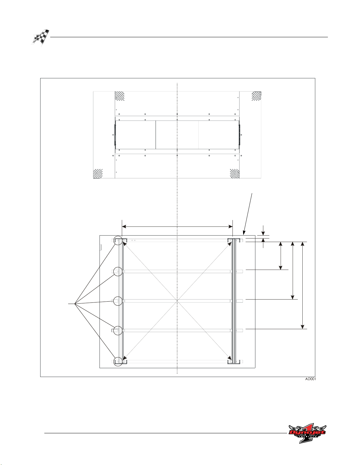
Before installing the track assembly, layout the entire track assembly in the pit using
the following instructions for position and alignment.
1 Line up the center line of the track assembly with the center line of the stationary
224 dyno.
2 Measure the following distances and set the track assembly in the pit as listed
below and shown in Figure 2-2.
• The track assembly should be 4.50 cm (1.75 in.) from the pit wall.
• The distance between the inside of the rails should be 184.15 cm
(72.50-inches +/- 0.06 in.).
• The distance from the first rail tie assembly to the first rail tie should be
44.77 cm (17.625 in.).
• The distance from the first rail tie assembly to the second rail tie is 94.30 cm
(37.125 in.).
• The distance from the first rail tie assembly to the third rail tie is 143.83 cm
(56.625 in.).
3 Verify the track assembly is square by measuring from corner to corner.
4 Mark and drill all ten holes, five on each side of the track assembly.
5 Set the track assembly aside.
6 Install the Red Head anchors. Refer to Appendix A for installation instructions.
INSTALLATION
Track Assembly
Version 3 In Ground Model 224 4WD Automotive Dynamometer Installation Guide
2-3
Page 24
CHAPTER 2
Track Assembly
224 stationary
dyno in pit
mark and
drill holes
track layout
in 4WD pit
center line for
stationary dyno and
track assembly
first rail tie assembly
first rail tie
second rail tie
third rail tie
184.15 cm
(72.5 in.)
pit wall
4.50 cm
(1.75 in.)
44.77 cm
(17.625 in.)
94.30 cm
(37.125 in.)
143.83 cm
(56.625 in.)
last rail tie assembly
Figure 2-2: Mark and Drill Holes for the Track Assembly
2-4
In Ground Model 224 4WD Automotive Dynamometer Installation Guide
Page 25

INSTALLING THE TRACK ASSEMBLY
Once all the holes are marked and drilled, install the track assembly.
1 Layout the first and last rail tie assemblies and the rail ties. Use the holes you
marked and drilled for placement of the rail tie assemblies and rail ties.
Note: The first rail tie has two holes for securing the cable track assembly. Verify
this rail tie assembly is closest in the pit to the stationary dyno.
2 Place the rail clamps over the rails.
3 Place the rails into the rail tie assemblies.
Note: For clarity, the pit is not shown.
holes for cable
track assembly
rail clamps
INSTALLATION
Track Assembly
rail
first rail tie
assembly
rail tie
last rail tie
assembly
Figure 2-3: Install the Track Assembly
Version 3 In Ground Model 224 4WD Automotive Dynamometer Installation Guide
2-5
Page 26

CHAPTER 2
Track Assembly
4 Loosely install the ten rail tie clips using one bolt, one lock washer, and one flat
washer per clip. There are five rail tie clips on each side of the track assembly.
5 Verify the track assembly is square and make any necessary adjustments.
6 Tighten all ten bolts.
Note: For clarity, the pit is not shown.
bolt
lock washer
flat washer
rail tie clip
rail
rail tie
anchor in
pit floor
Figure 2-4: Install the Rail Tie Clips
2-6
In Ground Model 224 4WD Automotive Dynamometer Installation Guide
Page 27

DYNO INSTALLATION
. . . . . . . . . . . . . . . . . . . . . . . . . . . . . . . . . . .
With the track assembly installed and secured to the pit floor, you are ready to install
the 224 4WD dyno.
REMOVING THE DYNO FROM THE CRATE
You will need to provide equipment capable of lifting a minimum of 1588 kg
(3500 pounds) to lift the dyno off the crate and into position in your dyno room. You
will also need a pair of straps capable of supporting 1588 kg (3500 pounds) to attach
to the dyno. Dynojet recommends using a single loop style strap.
1 Route the single loop straps around the knurled part of the drum as shown.
INSTALLATION
Dyno Installation
loop strap
drum
Figure 2-5: Loop Strap Placement
Version 3 In Ground Model 224 4WD Automotive Dynamometer Installation Guide
2-7
Page 28

CHAPTER 2
Dyno Installation
2 Using a forklift, carefully lift the dyno off the crate and move into position in your
dyno room.
Figure 2-6: Lift the Dyno off the Crate
2-8
In Ground Model 224 4WD Automotive Dynamometer Installation Guide
Page 29

PLACING THE DYNO IN THE PIT
You will need to keep the cable track routed underneath the dyno and towards the
stationary dyno.
1 Verify the rail clamps are positioned as shown in Figure 2-7.
2 Verify the dyno movement motor is facing away from the stationary dyno.
3 Using the forklift, gently lower the dyno onto the rails.
Note: Make sure the dyno movement motor is facing away from the stationary
dyno.
Note: For clarity, the pit in Figure 2-7 has been cut away to show the rail clamp
positions.
INSTALLATION
Dyno Installation
dyno movement motor facing
away from stationary dyno
cable track under dyno and
towards stationary dyno
Figure 2-7: Lower the Dyno into Pit
rail clamp
Version 3 In Ground Model 224 4WD Automotive Dynamometer Installation Guide
2-9
Page 30

CHAPTER 2
Dyno Installation
4 Secure the rail clamps to the cradle assembly on the dyno using two 3/8-inch
shoulder bolts and metal washers each.
5 Move the rail clamps up and down and verify they move freely.
5a Using a ruler, measure the vertical free play movement of each rail brake.
The free play should not exceed 5 mm (3/16 in.).
5b If the rail brake free play is out of specification, adjust by loosening the jam
nut and turning the adjusting bolt until free play is within specification.
Tighten the jam nut while holding the adjusting bolt.
6 Roll the dyno back and forth and verify the rail clamps are not binding.
Note: For clarity, the pit is not shown.
adjusting
bolt
cradle
assembly
rail clamp
free play
3/16"
jam nut
washer
bolt
Figure 2-8: Secure Dyno to Rail Clamps
2-10
In Ground Model 224 4WD Automotive Dynamometer Installation Guide
Page 31

INSTALLATION
ROUTING CABLES
. . . . . . . . . . . . . . . . . . . . . . . . . . . . . . . . . . .
Use the following instructions to identify and route the 224 4WD dyno cables to the
stationary dyno.
IDENTIFYING THE CABLES
cable brief routing description
A - 25-pin cable connects to the dyno electronics
B - data acquisition (pickup card) cable connects to the pickup card on the stationary 224 or
248 dyno
Routing Cables
C - multi purpose cable
• C-1 brake power cable
• C-2 load control cable
• C-3 temperature sensor cable
D - 224 4WD power cable connects to the power supply
E - dyno movement pendant connects to the dyno movement pendant
includes the following:
• two pin connector, connects to the two black
wires on the brake solenoid of the stationary dyno
• connects to the EPR on the 248 dyno with
optional prop air; or connects to the theta controller
with optional eddy current brake
• connects to the temperature sensor on the
optional prop air brake on the 248 dyno or to the
temperature sensor on the optional eddy current
brake
F - air hose connects to the air supply
Version 3 In Ground Model 224 4WD Automotive Dynamometer Installation Guide
2-11
Page 32

CHAPTER 2
Routing Cables
F - air hose
B - data acquisition
cable
cable track
A - 25-pin cable
C - multi purpose
cable
C-3 - temp sensor
connector
C-1 - brake power
connector
C-2 - load control
connector
E - dyno movement
pendent
Figure 2-9: Identifying the Cables
2-12
In Ground Model 224 4WD Automotive Dynamometer Installation Guide
D - 224 4WD power cable
Page 33

ROUTING THE CABLES
1 Secure the cable track to the front rail tie assembly using two 1/4-20 x 1-inch
button-head screws and two lock washers.
2 Route the 25-pin cable (A) from the cable track, through the 4WD pit conduit, and
connect the 25-pin cable to the dyno electronics.
3 Route the pickup card cable (B) from the cable track, through the conduit into the
stationary dyno pit, and connect to the pickup card.
INSTALLATION
Routing Cables
The optical pickup is very delicate. Be careful not to damage the optical
pickup. Rotate the drum slowly by hand and verify the pickup tab passes
through the optical card without contact.
tab on dyno
optical pickup
pickup card
top view of pickup card, optical
pickup, and tab on dyno
Figure 2-10: Optical Pickup Card and Tab
4 Route the multi-purpose cable (C) from the cable track, through the conduit into
the stationary dyno pit, and attach the two pin connector (C-1) to the black brake
solenoid wires.
Note: The temperature sensor and load control cables are for 248 or 224xLC
dynos only.
For more detailed information on routing the temperature sensor and prop air
cables, refer to the Proportional Air Brake Installation Guide (P/N 98212103).
For more detailed information on routing cables for 224xLC dynos, refer to
“Routing Cables—224xLC” on page 2-18.
Note: The cables from the pressure sensor do not need to be connected when the
4WD dyno is present.
Version 3 In Ground Model 224 4WD Automotive Dynamometer Installation Guide
2-13
Page 34

CHAPTER 2
Routing Cables
(C-1) to brake
solenoid
(B) pickup
card cable
224 stationary dyno
computer
monitor
cable track
248 or
224xLC
only
(C) multi-
purpose cable
pit conduit
dyno
electronics
224 4WD dyno
pit conduit
(A) 25-pin cable
Figure 2-11: Routing Cables—224 224-4WD
2-14
In Ground Model 224 4WD Automotive Dynamometer Installation Guide
Page 35

INSTALLATION
Routing Cables
(C) multi-
purpose
cable
(C-1) to brake
solenoid
248 stationary dyno
computer
monitor
cable
track
pit
conduit
(B) pickup
card cable
224 4WD dyno
dyno
electronics
pit conduit
(A) 25-pin cable
Figure 2-12: Routing Cables—248 224-4WD
Version 3 In Ground Model 224 4WD Automotive Dynamometer Installation Guide
2-15
Page 36

CHAPTER 2
Routing Cables
5 Route the air hose (F) from the cable track, through the conduit, and connect to
your clean, dry air supply at 100 psi.
Note: Verify the stationary dyno has clean dry air supplied to the air brake;
regulated to 100 psi for 224 stationary dynos and 60 psi for 248 stationary dynos.
The air brake comes installed with a hose barb for a 3/8-inch inside diameter air
hose. If your hose does not have an inside diameter of 3/8-inch then you will need
an air hose nipple (1/4-inch NPT) to connect your clean, dry shop air supply to
the dyno. Once the pressure is connected, the air brake is ready to use.
6 Route the power cable (D) from the cable track, through the conduit, and connect
to the power supply. Plug the power supply into your power source.
7 Connect the power supply to the dyno electronics. Plug the power supply into
your power source.
8 Route the dyno movement pendant cable (E) from the cable track, through the
conduit, and connect to the pendant.
pit
conduit
(F) air
hose
224 stationary dyno
computer
monitor
224 4WD dyno
cable track
(F) air
hose
pit conduit
(E) dyno movement
pendant
pit conduit
(D) power cable
dyno
electronics
power supply for dyno
electronics
Figure 2-13: Routing Cables Continued—224 224-4WD
2-16
In Ground Model 224 4WD Automotive Dynamometer Installation Guide
power supply for
4WD dyno
Page 37

INSTALLATION
Routing Cables
pit
conduit
248 stationary dyno
(E) dyno movement
pendant
computer
monitor
224 4WD dyno
pit
conduit
pit conduit
(D) power cable
dyno
electronics
(F) air hose
power supply for the
dyno electronics
Figure 2-14: Routing Cables Continued—248 224-4WD
Version 3 In Ground Model 224 4WD Automotive Dynamometer Installation Guide
power supply for the
4WD dyno
2-17
Page 38

CHAPTER 2
Routing Cables—224xLC
ROUTING CABLES—224XLC
. . . . . . . . . . . . . . . . . . . . . . . . . . . . . . . . . . .
Use the following instructions for routing cables when the 224 stationary dyno is
equipped with an eddy current brake.
1 Connect the temperature sensor cable from the eddy current brake to the
multi-purpose cable (C-3).
2 Connect the pickup card cable (B) to the pickup card.
3 Route the brake power cable from the eddy current brake through the pit cover
support and over to the Theta Controller (underneath).
4 Route the input power cable from the Theta Controller through pit cover
support, through the PVC conduit in the pit (not used by any other cables), and to
your power source.
Refer to the Eddy Current Brake Installation and User Guide for Model 224 Pit
Automotive Dynamometers (P/N 98215101) for more information.
5 Locate the four position terminal strip.
6 Connect the control cable from the Theta Controller to the terminal strip as
shown in Figure 2-16 on page 2-19.
7 Connect the load control cable (C-2) to the terminal strip as shown in Figure 2-16
on page 2-19.
input power cable
theta controller
2-18
In Ground Model 224 4WD Automotive Dynamometer Installation Guide
control cable
terminal strip
Figure 2-15: Routing Cables—224xLC
pickup cable
from 4WD dyno
C-3 temperature
sensor cable
C-1 brake power
cable connected to
brake solenoid
(C) multi-purpose
cable from 4WD dyno
C-2 load control cable
Page 39

INSTALLATION
Routing Cables—224xLC
(C-2) load
control cable
(C-3) temperature
sensor cable
V- blue
V+ orange
O+ white
O- green
terminal strip
black
red
white
green
(C-1) brake power
cable
(C) multi-purpose wire
Figure 2-16: Wiring the Terminal Strip—224xLC
Version 3 In Ground Model 224 4WD Automotive Dynamometer Installation Guide
control cable from theta
controller
2-19
Page 40

CHAPTER 2
Chain Installation
CHAIN INSTALLATION
. . . . . . . . . . . . . . . . . . . . . . . . . . . . . . . . . . .
Use the following instructions to install the chain assembly.
1 Secure the two idler sprockets to the cradle assembly using one
grade 5, 1/2-13 UNC x 1.5-inch bolt and spacer each as shown in Figure 2-17.
Note: The bolts, sprockets, and spacers will be packaged together.
cradle
assembly
spacer
idler
sprocket
bolt
Figure 2-17: Install the Idler Sprockets
2-20
In Ground Model 224 4WD Automotive Dynamometer Installation Guide
Page 41

INSTALLATION
Chain Installation
2 Route the chain over the top of the drive sprocket, under the idler sprockets, and
over to the rail tie assembly.
3 Secure each end of the chain to the rail tie assembly using one 1/2-13 nut.
Note: Verify the chain does not droop.
chain
drive
sprocket
idler
sprocket
rail tie
assembly
chain-
no droop
chain
Figure 2-18: Route and Secure the Chain
nut
rail tie
assembly
nut
Version 3 In Ground Model 224 4WD Automotive Dynamometer Installation Guide
2-21
Page 42

CHAPTER 2
4WD Dyno Movement Test
4WD DYNO MOVEMENT TEST
. . . . . . . . . . . . . . . . . . . . . . . . . . . . . . . . . . .
Verify the movement of the 4WD dyno before installing the grates.
1 The Breakout board jumper settings are preset, however, verify jumpers J1 and J2
are set for the 4WD proportional air brake as shown in Figure 2-19.
Note: The Breakout board is inside the 4WD control box. Refer to Figure 1-2 for
more information on locating the 4WD control box.
load control
jumpers
J1 and J2
four wheel drive
prop air brake
jumper settings
Figure 2-19: Verify the Jumper Settings
2 Verify the air motor lubricator bowl is full with oil. Refer to page 4-12 for
information on how to check the air motor lubricator.
Note: The air motor lubricator bowl is inside the 4WD control box. Refer to
Figure 1-2 for more information on locating the 4WD control box.
3 Turn the dyno electronics on.
4 Turn the air on.
5 Press the red button on the dyno pendant. The button should light up indicating
the brakes are activated. The red button will control the brakes on both dynos.
6 Verify the brakes are working properly by pressing the red button a few times to
cycle the brakes.
7 With the brakes on, press and hold the "in" button on the dyno movement
pendant. You should hear air venting, and the rail clamps releasing.
Note: The dyno brakes MUST be on or the 4WD dyno will not move.
8 Keep holding the "in" button down until you see the motor shaft begin to turn.
9 Repeat this procedure holding the "out" button.
2-22
In Ground Model 224 4WD Automotive Dynamometer Installation Guide
Page 43

Grate Placement and Installation
GRATE PLACEMENT AND INSTALLATION
. . . . . . . . . . . . . . . . . . . . . . . . . . . . . . . . . . .
Before installing the 4WD grates, and if you have a 248 stationary dyno, you will need
to replace three of the existing 248 pit covers with three new covers for use with the
224 4WD dyno.
part number description
2484075 Cover, Pit, Non Brake Side, Center
2481076 Cover, Pit, Non Brake Side, Right
2481077 Cover, Pit, Non Brake Side, Left
INSTALLING THE NEW 248 PIT COVERS
You need to replace three of the existing 248 pit covers with new covers for use with
the 224 4WD dyno.
1 Remove the button-head bolts securing the three existing pit covers and set aside.
2 Remove the existing pit covers.
3 Secure the new left and right side pit covers using two of the reserved bolts each.
4 Secure the new center pit cover using three of the reserved bolts.
INSTALLATION
248 stationary dyno
right side
pit cover
center pit
cover
left side pit
cover
Figure 2-20: 248 Pit Covers
Version 3 In Ground Model 224 4WD Automotive Dynamometer Installation Guide
2-23
Page 44

CHAPTER 2
Grate Placement and Installation
INSTALLING THE CROSS BRACE ASSEMBLIES
Each cross brace assembly has two halves that must be assembled together before
installing the cross brace assemblies in the pit.
1 Loosely connect the two halves of each cross brace using three 3/8-inch bolts.
2 Slide the brace halves apart until the assembly is the same width as the pit.
3Tighten the bolts.
width of pit
Figure 2-21: Connecting the Cross Brace Halves
2-24
In Ground Model 224 4WD Automotive Dynamometer Installation Guide
Page 45

INSTALLATION
Grate Placement and Installation
4 Using the dyno movement pendant, move the dyno to the front of the pit (closest
to the stationary dyno).
5 Hold the cross brace assembly approximately one inch from the dyno frame with
the top of the brace flush with the pit room floor.
6 Mark and drill the two holes on each end of the brace assembly.
7 Install the Red Head anchors. Refer to Appendix A for installation instructions.
8 Secure the cross brace to the pit wall using four bolts, lock washers, and flat
washers.
9 Using the dyno movement pendant, move the dyno to the rear of the pit and
repeat these steps.
10 Once the cross brace assemblies are secured, verify the dyno moves free and does
not hit the cross braces.
pit floor
cross brace
assembly
cross brace
assembly
pit room
floor
approx. 1"
front of pit
rear of pit
Figure 2-22: Installing the Cross Brace Assembly
bolt
lock washer
flat washer
Version 3 In Ground Model 224 4WD Automotive Dynamometer Installation Guide
2-25
Page 46

CHAPTER 2
Grate Placement and Installation
INSTALLING THE CENTER GRATES AND CENTER PLATE
1 Place the center grates on the dyno so the long lip faces the drum.
2 Loosely secure each grate to the dyno using two 3/8 x 3-inch button-head bolts.
3 Loosely secure the center plate to the grates using ten 3/8 x 1-inch button-head
bolts.
4 Loosely secure the center plate to the dyno using one 3/8 x 3-inch button-head
bolt.
5 Verify the center plate and grates are aligned with the dyno and tighten all the
bolts.
center plate
long lip on
center grate
2-26
In Ground Model 224 4WD Automotive Dynamometer Installation Guide
Figure 2-23: Installing the Center Grates and Center Plate
center plate
Page 47

INSTALLING THE SIDE GRATES
The side grates do not secure to the dyno.
1 Lay the side grates on the side of the dyno with the bolt holes on the outside.
2 Center the side grates with the pit opening.
3 Verify there is a one inch gap between the side grates and the center grates.
4 Verify the side grates do not touch the dyno or the center grates.
5 Mark and drill the ten holes needed to secure each side grate to the pit floor.
6 Install the Red Head anchors. Refer to Appendix A for installation instructions.
7 Secure each side grate to the pit floor using ten bolts, lock washers, and flat
washers.
INSTALLATION
Grate Placement and Installation
bolt holes on
outside
center grate with
pit opening
side grate
mark and
drill holes
center grate
one inch gap
between grates
Figure 2-24: Installing the Side Grates
Version 3 In Ground Model 224 4WD Automotive Dynamometer Installation Guide
2-27
Page 48

CHAPTER 2
Grate Placement and Installation
INSTALLING THE DRUM GUARDS
Install each drum guard to the center grates using two 3/8 x 1-inch button-head bolts.
There are four drum guards, two per side.
center grate
drum guard
drum guard
Figure 2-25: Installing the Drum Guards
2-28
In Ground Model 224 4WD Automotive Dynamometer Installation Guide
Page 49

D
YNO
C HAPTER
3
E
LECTRONICS
This chapter describes the specifications for the dyno electronics. To ensure safety
and accuracy in the procedures, perform the procedures as they are described.
This chapter is divided into the following categories:
• Dyno Electronics, page 3-2
• Atmospheric Sensing Module, page 3-2
•RPM Module, page 3-3
• Dynamometer Input/Output Module, page 3-4
• CPU Module, page 3-5
In Ground Model 224 4WD Automotive Dynamometer Installation Guide
3-1
Page 50

CHAPTER 3
Dyno Electronics
DYNO ELECTRONICS
. . . . . . . . . . . . . . . . . . . . . . . . . . . . . . . . . . .
The standard DynoWare EX+ dynamometer electronics package is comprised of four
interconnected modules: Atmospheric Sensing Module, RPM Module, Dynamometer
Input/Output Module, and the CPU Module.
system expansion
connector
atmospheric
sensing module
inductive pickup socket
25-pin socket
9-pin, RS-232 socket
Figure 3-1: Dyno Electronics
ATMOSPHERIC SENSING MODULE
The atmospheric sensing module measures absolute pressure, air temperature, and
relative humidity. These measurements are used by WinPEP to correct power and
torque measurements to standard atmospheric conditions according to a DIN, SAE, or
other formula.
LED indicator description
The green LED glows when the atmospheric sensing
module is receiving power.
RPM module
dynamometer
input/output module
9-pin, hand held
pendant
CPU module
3-pin power plug
The flashing amber LED indicates the module processor
is operating properly.
3-2
In Ground Model 224 4WD Automotive Dynamometer Installation Guide
Page 51

RPM MODULE
The RPM module receives and processes signals from up to two inductive pickups for
measurement of engine RPM. Each input has an automatic gain circuit to compensate
for a wide variance of ignition systems.
LED indicator description
DYNO ELECTRONICS
Dyno Electronics
Figure 3-2: RPM Module
The green LED glows when the RPM module is receiving
power.
The amber LED flashes when an RPM signal is detected.
A steady flash rate, proportional to engine RPM, indicates
a good RPM signal.
These connectors are the inputs for both primary and
secondary inductive pickup clips. Either input may be
used with a primary inductive pickup or a secondary
inductive pickup on a single ended coil. Both inputs can
be used for a wasted spark ignition.
Version 3 In Ground Model 224 4WD Automotive Dynamometer Installation Guide
3-3
Page 52

CHAPTER 3
Dyno Electronics
DYNAMOMETER INPUT/OUTPUT MODULE
The dynamometer input/output module sends and receives data from the
dynamometer and the hand-held pendant. The module also contains a buzzer and
light which are activated when either the vehicle or the dynamometer speed limit is
approached.
Figure 3-3: Dynamometer Input/Output Module
LED indicator description
The green LED glows when the dynamometer
input/output module is receiving power.
The amber LED flashes proportionally to dynamometer
drum RPM.
This 25-pin connector attaches to the shielded cable from
the dynamometer.
This 9-pin connector attaches to the hand held pendant
which houses the button used to start/stop acquiring
data. The pendant may also contain a brake switch.
3-4
In Ground Model 224 4WD Automotive Dynamometer Installation Guide
Page 53

CPU MODULE
The CPU module contains a 32-bit processor which acquires data from the expansion
modules and communicates to the main computer running the WinPEP software. The
processor queries the expansion modules to determine their identity and capabilities.
LED indicator description
DYNO ELECTRONICS
Dyno Electronics
Figure 3-4: CPU Module
The green LED glows when the CPU module is receiving
power.
The blue LED is lighted when data from the modules is
being acquired and saved.
One of these connectors is used to communicate to the
main computer. The 9-pin connector (left) attaches to
the PC’s RS-232 serial communications port.
This connector provides a synchronization signal to a
third party data acquisition system.
This connector provides 12 volt DC power to a third
party data acquisition system.
This connector accepts 12 volt DC power from a power
supply or battery. The adjacent LED glows bright green
when power is properly connected.
When this switch is on, power is supplied to all
connected modules.
Version 3 In Ground Model 224 4WD Automotive Dynamometer Installation Guide
3-5
Page 54

Page 55

B
ASIC
D
YNO
C HAPTER
O
PERATION
4
The Dynojet Dynamometer gives you the state of the art technology, durability, and
accuracy that you need. Dynojet’s advanced engineering delivers the precise
horsepower measurements a technician needs to make quick and accurate
evaluations of engine performance and drive train problems.
This chapter includes instructions for basic dyno operation. For more detailed
instructions, refer to the WinPep 7 User Guide. This manual can also be found on
your WinPep CD or at www.dynojet.com/manuals/shtml.
This chapter is divided into the following categories:
• Loading the Car, page 4-2
• Connecting the RPM Pickup, page 4-5
•Pre-Run Inspection, page 4-8
• Making a Test Run, page 4-10
• Preventative Maintenance, page 4-11
In Ground Model 224 4WD Automotive Dynamometer Installation Guide
4-1
Page 56

CHAPTER 4
Loading the Car
LOADING THE CAR
. . . . . . . . . . . . . . . . . . . . . . . . . . . . . . . . . . .
Use the following steps to load a car on the dyno.
1 Verify your computer is running. Set the dyno brake on by pressing the red
button on the hand held pendant.
2 For four or all-wheel drive vehicles, measure the wheel base on the vehicle and
adjust the 224 4WD dyno to the dimension before driving the vehicle on the
dyno.
Do not make any adjustments with the vehicle on the dyno.
3 Drive the vehicle onto the dyno and align the vehicle straight with the dyno.
4 Stop the vehicle when the drive axle(s) is centered on the drum(s).
four or all-wheel
drive vehicles
adjust wheel base of
224 4wd dyno
center drive axle on both dyno drums
Figure 4-1: Center the Drive Axles on the Drums
5 When the vehicle is positioned properly on the dyno, shut the engine off.
• If the vehicle has an automatic transmission, place it in park.
• If the vehicle has a manual transmission, place it in gear.
6 Set the vehicle’s emergency brake.
7 Secure the non-drive wheels using the provided tire chocks. Do not use tire
chocks for four wheel drive vehicles.
4-2
In Ground Model 224 4WD Automotive Dynamometer Installation Guide
Page 57

BASIC DYNO OPERATION
8 Attach the tie-down straps.
Rear Wheel Drive
• Attach two tie-down straps from secure anchor points to the rear of the
vehicle. Attach additional tie-down straps from the rear of the vehicle as shown
in Figure 4-2.
• Attach two tie-down straps from secure anchor points to the front of the
vehicle.
Front Wheel Drive
• Attach two tie-down straps from secure anchor points to the rear of the
vehicle.
• Attach two tie-down straps from secure anchor points to the front of the
vehicle. Attach additional tie-down straps across the front of the vehicle to
form a crisscross.
Four Wheel (All-Wheel) Drive
• Attach two tie-down straps from secure anchor points to the rear of the
vehicle. Attach additional tie-down straps across the rear of the vehicle to form
a crisscross.
• Attach two tie-down straps from secure anchor points to the front of the
vehicle. Attach additional tie-down straps across the front of the vehicle to
form a crisscross.
Loading the Car
rear wheel drive
Figure 4-2: Attach the Tie-down Straps
Version 3 In Ground Model 224 4WD Automotive Dynamometer Installation Guide
front wheel drive
four wheel drive
4-3
Page 58

CHAPTER 4
Loading the Car
9 Tighten the tie-down straps evenly making sure that the drive wheels remain
centered on the drum.
The tie-down straps should always be connected to the vehicle’s solid axle or
the suspension control arms. Factory tie-down hooks connected to the
vehicle’s frame may be used on the end opposite the drive wheels (for
example: the front end of a rear driven vehicle).
10 Release the brake on the vehicle and the dyno.
11 Start the vehicle and put the transmission into first gear or drive.
12 Press the accelerator pedal so the drums begin turning slowly. While the drums
are slowly turning, get a feel for the stability of the vehicle.
13 Check all the straps and ensure the vehicle is tracking straight on the dyno.
4-4
In Ground Model 224 4WD Automotive Dynamometer Installation Guide
Page 59

BASIC DYNO OPERATION
CONNECTING THE RPM PICKUP
. . . . . . . . . . . . . . . . . . . . . . . . . . . . . . . . . . .
Your Dynojet dynamometer includes a primary wire inductive pickup and two
secondary wire inductive pickups. These small “clothespin like” inductive pickups are
used to sense RPM. An RPM pickup is required if you want to view torque graphs.
Generally you will use one secondary wire inductive pickup on a spark plug wire.
Vehicles with wasted spark ignition systems may require two secondary inductive
pickups. On a wasted spark ignition, typically one coil will be connected to two spark
plug wires. Attach one secondary pickup to each of these wires. If the pickups are
connected to two plug wires that do not fire at the same time, an erratic RPM readout
may occur. The primary wire inductive pickup senses RPM pulses from the coil.
Although this pickup location generally works better, it is harder to find the correct
location to connect the RPM pickup.
Note: If a pickup is not being used, disconnect it from the dyno electronics to
prevent any stray pick up of signals.
The optional Optical Sensor is useful on diesel powered vehicles, MSD ignitions, and
other high RFI ignition systems. For more detailed information on the Optical Sensor,
refer to the Optical RPM Sensor Installation Guide (P/N 98295109).
Connecting the RPM Pickup
Inductive pickups are very fragile. The ferrite core can easily be damaged and
is not covered under warranty. Dropping, snapping, vibration, and heat can all
damage the ferrite core.
The dyno electronics RPM module contains the electronics that sense the RPM pulses.
An auto-gain circuit looks at only the peak voltage of the vehicle’s spark, ignoring the
lower voltages to help reduce electronic noise problems. Wasted spark ignition
systems will produce a lower voltage level on the exhaust stroke than the
compression stroke. By definition of the auto-gain circuit, lower voltage spark levels
will be ignored, missing every other spark the vehicle would produce.
RPM PICKUP DESCRIPTIONS
RPM pickup description
Secondaries (Non- wasted spark system) Use one secondary pickup. Unplug the other pickup from the RPM
module and set the degrees between plug fires to 720° in WinPEP.
Secondaries (Wasted spark ignition
system)
Primary pickup Attach the primary wire pickup to the primary side of the coil. Set
Optional Optical RPM Sensor Attach the sensor wire to the RPM module, also be sure to plug in
Use two secondary pickups. Attach one pickup on each spark plug
wire on the same coil and set the degrees between plug fires to
360° in WinPEP.
the degrees between plug fires by taking 720/number of cylinders.
For example, the number of degrees between plug fires on a V-8
engine with a single coil is 720/8=90 degrees.
the small power lead into the CPU module. The other end of the
wire attaches to the Optical Sensor. Set the degrees between plug
fires to 360° in WinPEP. Refer to the Optical RPM Sensor
Installation Guide (P/N 98295109).
Version 3 In Ground Model 224 4WD Automotive Dynamometer Installation Guide
4-5
Page 60

CHAPTER 4
Connecting the RPM Pickup
CONNECTING THE SECONDARY INDUCTIVE PICKUP
The secondary inductive pickup cannot be in contact with, or it’s connecting wire be
crossing, other engine electrical wires or stray RF interference may result.
1 Clip the secondary inductive pickup around one spark plug wire.
2 Route the inductive pickup cable clear of devices that produce electronic noise
(spark plug wires, coil wire, coil etc.).
Note: Inductive pickup placement is important. Position the inductive pickup so
that it is not making contact with any other spark plug wires. Separate the spark
plug wire from the spark plug wire bundle for proper operation.
Note: You must ground the vehicle to the dyno for the electronics to function
properly.
connect secondary
inductive pickup on a
single spark plug wire
automobile
distributor
Figure 4-3: Secondary Inductive Pickup
Figure 4-4: Separate Spark Plug Wire
4-6
In Ground Model 224 4WD Automotive Dynamometer Installation Guide
Page 61

CONNECTING THE PRIMARY INDUCTIVE PICKUP
The primary inductive pickup cannot be in contact with, or it’s connecting wire be
crossing, other engine electrical wires or stray RF interference may result.
1 Clip the primary inductive pickup around the primary side of the coil.
2 Route the primary wire cable clear of devices that produce electronic noise.
Note: You must ground the vehicle to the dyno for the electronics to function
properly.
BASIC DYNO OPERATION
Connecting the RPM Pickup
coil
Figure 4-5: Primary Inductive Pickup
connect primary
inductive pickup on the
negative side of the coil
Version 3 In Ground Model 224 4WD Automotive Dynamometer Installation Guide
4-7
Page 62

CHAPTER 4
Pre-run Inspection
PRE-RUN INSPECTION
. . . . . . . . . . . . . . . . . . . . . . . . . . . . . . . . . . .
Perform a vehicle inspection before making a run.
• Check the radiator coolant and oil levels.
•Check the fuel source.
• Rotate the drum(s) and check for rocks caught in the tire tread that could fly out.
• Check the tire pressure and tire speed rating. Improperly inflated tires or
exceeding the maximum speed rating can result in premature wear or severe tire
damage. Make sure the tire has no major deficiencies (cracks in sidewalls, tread life,
etc.).
• Visually inspect the vehicle. Make sure it is in safe running order.
• Make sure ear protection and safety glasses are used when the dyno is being
operated.
• Check the tie-down straps to make sure that they are tight and secured.
• Check the drive tires to be sure that they are aligned correctly on the
dynamometer’s drums.
• Keep all rotating components clear at all times.
• Only the operator should be near the dyno or the vehicle during the test.
• Never allow any person(s) to stand behind the dyno or vehicle when it is being
operated.
• Perform any other safety inspections appropriate to running your vehicle on the
dyno.
Never allow any person(s) to stand behind the dyno or vehicle when it is being
operated. Only the operator should be near the dyno or the vehicle during the
test.
BEFORE STARTING THE ENGINE
Connect an exhaust hose or hoses (if dual exhaust) on the vehicle, make sure the
hose fits over the tail pipe, is not plugged or kinked and the hose is vented correctly
out of the dyno room.
Engine exhaust contains poisonous carbon monoxide gas. Breathing it could
cause death. Operate machine in well ventilated area.
4-8
In Ground Model 224 4WD Automotive Dynamometer Installation Guide
Page 63

ENGINE WARM UP
Warm the vehicle’s engine and drivetrain before beginning testing. Consistent engine
temperatures will assure your runs are repeatable.
AFTER ENGINE WARM UP
Always leave the vehicle in park (automatic transmission) or in first gear (manual
transmission), with the engine off, and make sure the emergency brake and the dyno
brake are on when you get out of the vehicle.
• Fix any fuel, oil, or coolant leaks that may have shown up after engine warm up and
check the carburetor for leaks.
• Any loud or unusual engine noises or excessive exhaust smoke should be resolved
before continuing.
BASIC DYNO OPERATION
Pre-run Inspection
Version 3 In Ground Model 224 4WD Automotive Dynamometer Installation Guide
4-9
Page 64

CHAPTER 4
Making a Test Run
MAKING A TEST RUN
. . . . . . . . . . . . . . . . . . . . . . . . . . . . . . . . . . .
Dyno runs provide safe, reliable road testing right in the shop. The dyno allows you to
measure, record, and diagnose performance problems quickly. The dyno combined
with WinPEP 7 produces consistent, easily interpretable power graphs. Use the
following instructions to ensure repeatable and accurate measurements.
1 Verify the vehicle is secured properly.
2 Place the vehicle in a low gear and release the dyno brake using the hand held
pendant.
3 Slowly accelerate the vehicle to 20 m.p.h.
4 Test the tachometer operation.
4a Rev the engine. The gauges on the computer screen should be moving. If
the tachometer is moving but not registering the correct RPM values, the
number of degrees of revolution of the crank shaft (the plug fires number) is
incorrect.
4b Stop the vehicle, return to the MakeRun Configuration dialog box, and enter
the correct value for the plug firing order.
5 Press the red brake button to apply 100% braking and slow down the vehicle.
Using the vehicle’s own brakes to slow or stop the drum at speeds over 30
m.p.h. can severely over heat the brake parts. Dynojet dynamometers with the
air brake or eddy current brake accessory can be used to slow the vehicle and
drum to a full stop at any speed. The vehicle’s brakes should be used in an
emergency stop situation only.
6 Shut the engine off and put the vehicle in gear (manual transmission) or park
(automatic transmission).
7 Set the vehicle’s parking brake and leave the dyno brake on.
8 Perform a final inspection.
• Verify the drive tire’s alignment on the dyno drums.
• Make any adjustments to the tie-down straps as needed.
• Perform any other safety checks that you deem appropriate to your particular
situation.
You are now ready to make a high speed run on the dyno. Refer to your WinPep 7
User Guide for more detailed instructions.
4-10
In Ground Model 224 4WD Automotive Dynamometer Installation Guide
Page 65

BASIC DYNO OPERATION
PREVENTATIVE MAINTENANCE
. . . . . . . . . . . . . . . . . . . . . . . . . . . . . . . . . . .
This section covers maintenance items for all model 224 dynos. For model 248
maintenance information, refer to the Maintenance Guide for Automotive
Dynamometers (P/N 98119101).
MODEL 224 AND 224 4WD DYNOS—THINGS TO CHECK
• Check all air fittings for leaks monthly. Correct any leaks found.
• Once per month verify that the drum brake pressure gauge reads 55 to 65psi
(380 to 450kPa). Adjust regulator if pressure is out of specification.
•Dyno Bearing Grease:
Under steady use, over 25 runs per day, each bearing should receive .65oz of a
recommended grease every two months.
Under occasional use, less than 25 runs per day, each bearing should receive
.65oz of a recommended grease every six months.
Recommended Grease:
Preventative Maintenance
grease specification description
thickener Lithium 12 Hydroxy Stearate
oil Petroleum
thickness NLGI 2
operating temperature -20°F to 200°F, intermittent to 250°F
EP additive yes
examples Mobil Mobilith AW-2
Version 3 In Ground Model 224 4WD Automotive Dynamometer Installation Guide
4-11
Page 66

CHAPTER 4
Preventative Maintenance
MODEL 224 DYNOS WITH 4WD ATTACHMENT—THINGS TO CHECK
• Check the air motor lubricator once per month, fill as necessary. Disconnect the air
before removing the lubricator bowl.
• Shut off or disconnect the air supply to the dyno, and follow lock out
procedure.
• Press and hold the dyno in or out movement switch until you cannot hear any
air going through the movement motor.
Before running the Gast Air Motor, remove the lubricator bowl and fill the bowl
with oil.
Note: Use a non-detergent SAE #10 automotive engine oil (Gast Part #AD220).
remove bowl and
fill to line with oil
Figure 4-6: Check Air Motor Lubricator
• Check customer supplied air filter/dryer daily, empty and clean as necessary.
• Inspect the 4WD dyno movement rails for debris once per month. Clear any debris
from the rails.
4-12
In Ground Model 224 4WD Automotive Dynamometer Installation Guide
Page 67

CHECKING THE 224 DRUM BRAKE SHOE CLEARANCE
The 224 drum brake shoe clearance must be checked once per month.
1 Remove the air from the system.
1a Shut off or disconnect the air supply to the dyno, and follow lock out
procedure.
1b Using the red button on the pendant, cycle the drum brakes on and off
several times until no air is heard.
2 Measure the gap between the brake shoe and the drum surface. This gap should
be 3 mm to 10 mm (.125 in. to .375 in.).
3 If the brake shoe clearance is out of specification perform the following steps:
3a Remove the two 3/8-inch bolts and washers that secure the brake slave
cylinder to the dyno frame.
BASIC DYNO OPERATION
Preventative Maintenance
bolt
washer
washer
brake slave cylinder
Figure 4-7: Remove Bolts from Brake Slave Cylinder
brake shoe
Version 3 In Ground Model 224 4WD Automotive Dynamometer Installation Guide
4-13
Page 68

CHAPTER 4
Preventative Maintenance
3b Pull the slave cylinder away from the dyno being careful not to kink the
3c Screw the brake piston rod in to increase brake shoe clearance or out to
3d Attach the slave cylinder using the bolts and washers removed earlier.
3e Recheck brake shoe clearance. No part of the brake shoe should touch the
4 If you cannot adjust the brakes to specification, you will need new brake shoes.
Contact Dynojet.
Turn on or reconnect the air supply and check that the drum brakes operate
before replacing the covers and using the dyno.
brake line.
decrease brake shoe clearance.
drum!
brake shoe
brake piston rod
brake slave cylinder
Figure 4-8: Pull Cylinder Away
4-14
In Ground Model 224 4WD Automotive Dynamometer Installation Guide
Page 69

BASIC DYNO OPERATION
MODEL 224 4WD—INSPECTING THE RAIL BRAKE CLEARANCE
Inspect the rail brake clearance once per month.
1 Shut off or disconnect the air supply to dyno, and follow your company’s lock out
procedure.
2 Press the red button on the pendant to activate the drum brakes; the button will
be lit.
3 Press and hold the dyno movement switch in either the in or out position until
you cannot hear any air going through the movement motor.
4 Using the red button on the pendant, cycle the drum brakes on and off several
times until no air is heard.
5 Remove the grate cover from the dyno to access the pit.
6 Using a ruler, measure the free play movement of each rail brake. The free play
should not exceed 5 mm (3/16 in.).
7 If the rail brake free play is out of specification adjust by loosening the jam nut
and turning the adjusting bolt until free play is within specification. Tighten the
jam nut while holding the adjusting bolt.
Preventative Maintenance
Figure 4-9: Inspect the Rail Brake Clearance
Version 3 In Ground Model 224 4WD Automotive Dynamometer Installation Guide
4-15
Page 70

Page 71

R
ED
H
EAD
A PPENDIX
A
A
NCHOR INSTALLATION
This appendix contains instructions for installing the Red Head Multi-Set™II Anchors.
The anchors will be used to secure the dyno to concrete. To ensure safety and
accuracy in the procedures, perform the procedures as they are described. Be sure to
read and understand the warnings included in this appendix.
WARNINGS
Always wear safety glasses and other necessary protective devices or apparel
when installing or working with anchors.
ITW Ramset/Red Head Multi-Set II Anchors are designed to operate properly
only when installed with ITW Ramset/Red Head brand Setting Tools.
The use of a 24 to 40 ounce hammer is recommended for expanding Multi-Set II
anchors.
The use of carbide drill bits manufactured with ANSI B94. 12-77 drill bit diameter
requirements is recommended for installation of this anchor.
Not recommended for use in lightweight masonry material such as block or brick.
Use of core drills is not recommended to drill holes for use with this anchor.
Not recommended for use in new concrete which has not had sufficient time to cure.
Anchor spacing and edge distance requirements (anchor installation locations) are
the responsibility of the engineer of record.
CONTACT INFORMATION FOR ITW RAMSET/RED HEAD
Contact ITW Ramset/Red Head at 1-630-350-0370, or 1300 North Michael Drive,
Wood Dale, IL 60191.
In Ground Model 224 4WD Automotive Dynamometer Installation Guide
A-1
Page 72

APPENDIXA
Installation
INSTALLATION
. . . . . . . . . . . . . . . . . . . . . . . . . . . . . . . . . . .
Use the table below to determine the catalog number, drill bit size, minimum hole
depth, and setting tool catalog number.
setting tool
catalog number drill bit size minimum hole depth
Carbon Steel
RM-38/RL-38 (9.5 mm)
Use the following instructions to install the Red Head anchors.
1 Drill the hole in the concrete the same outside diameter as the anchor being used
to any depth exceeding minimum embedment.
1/2-inch 1 5/8-inch (41.2 mm) RT-138
catalog number
Figure A-1: Red Head Anchor—Drill the Hole
2 Insert the anchor.
anchor
Figure A-2: Red Head Anchor—Insert the Anchor
A-2
In Ground Model 224 4WD Automotive Dynamometer Installation Guide
Page 73

RED HEAD ANCHOR INSTALLATION
Installation
3 Using a hammer, drive the anchor flush with the surface of the concrete, or below
the surface if the hole depth exceeds minimum embedment.
Figure A-3: Red Head Anchor—Drive the Anchor Flush
4 Using a hammer, expand the anchor with the setting tool. The anchor is properly
expanded when the shoulder of the setting tool is flush with the top of the
anchor.
Note: Use only Ramset/Red Head setting tools to insure proper installtion.
setting tool
Figure A-4: Red Head Anchor—Expand the Anchor
Version 3 In Ground Model 224 4WD Automotive Dynamometer Installation Guide
A-3
Page 74

Page 75

I
NDEX
224 4WD power cable
identifying 2-11
routing 2-16
248 pit covers 2-23
25-pin cable
identifying 2-11
routing 2-13
A
air brake 2-16
air hose
identifying 2-11
routing 2-16
air motor lubricator 4-12
atmospheric sensing module 3-2
B
battery hazards vi
brake power cable 2-18
brake power connector 2-11
brake pressure 4-11
breakout board
jumper settings 2-22
C
cable track 2-13
center grates 2-26
center plates 2-26
chain
drive sprocket 2-21
idler sprockets 2-20
installing 2-20–2-21
chassis
drum 1-4
height 1-4
length 1-4
weight 1-4
width 1-4
compressed air requirements 1-6
computer specifications 1-6
control cable
routing 2-18
conventions 1-3
CPU module 3-5
cradle assembly 2-10
crate
removing the dyno 2-7
unpacking dyno 2-2
cross brace assemblies 2-24
D
dimensions
dyno 1-5
pit 1-10
disclaimers v
document part number 1-1
drive sprocket 2-21
drum 1-4
drum brake shoe clearance 4-13
drum guards 2-28
dynamometer input/output module 3-4
dyno bearing grease 4-11
dyno electronics
atmospheric sensing module 3-2
CPU module 3-5
dynamometer input/output module 3-4
RPM module 3-3
dyno movement pendant cable
identifying 2-11
routing 2-16
dyno requirements 1-4–1-7
see also requirements
E
electrical requirements 1-6
electrostatic discharge vi
environmental requirements 1-7
ESD precautions vi
In Ground Model 224 4WD Automotive Dynamometer Installation Guide
Index-i
Page 76

INDEX
F
fire suppression 1-7
forklift requirements 1-7
G
grates 2-23–2-28
248 pit covers 2-23
center grates 2-26
center plates 2-26
cross brace assemblies 2-24
drum guards 2-28
side grates 2-27
ground hooks 1-7
H
hazards vii
height 1-4
I
idler sprockets 2-20
input power cable 2-18
J
jumper settings 2-22
L
length 1-4
load control cable
routing 2-18
load control connector 2-11
loading the car 4-2
M
making a test run 4-10
movement test 2-22
multi-purpose cable
brake power connector 2-11
identifying 2-11
load control connector 2-11
routing 2-13
temperature sensor connector 2-11
O
optical RPM sensor 4-5
P
pick-up cable
routing 2-18
pickup card cable
identifying 2-11
routing 2-13
pit 2-9
pit covers, 248 2-23
pit specifications 1-10
power supply 2-16
pre-run inspection 4-8–4-9
preventative maintenance 4-11–4-15
air motor lubricator 4-12
drum brake shoe clearance 4-13
dyno bearing grease 4-11
rail brake clearance 4-15
primary inductive pickup 4-7
R
rail brake 2-10
clearance 4-15
rail clamp 2-5
rail tie 2-5
rail tie assembly 2-5
rail tie clip 2-6
red head anchor
contact information A-1
installation A-2
setting tool A-3
warnings A-1
requirements
chassis 1-4
compressed air 1-6
computer specifications 1-6
electrical 1-6
environmental 1-7
fire suppression 1-7
forklift 1-7
ground hooks 1-7
tie-down straps 1-7
routing cables 2-11–2-17
224 4WD power 2-11, 2-16
25-pin 2-11, 2-13
air hose 2-11, 2-16
dyno movement pendant 2-11, 2-16
identifying 2-11
multi-purpose 2-11, 2-13
pickup card 2-11, 2-13
power supply 2-16
routing cables-224xLC 2-18–2-19
brake power 2-18
control cable 2-18
input power cable 2-18
load control cable 2-18
pick-up 2-18
temperature sensor 2-18
terminal strip 2-18
RPM module 3-3
RPM pickup 4-5–4-7
primary inductive pickup 4-7
secondary inductive pickup 4-6
S
secondary inductive pickup 4-6
setting tool A-3
side grates 2-27
strap 1-7, 2-7
Index-ii
In Ground Model 224 4WD Automotive Dynamometer Installation Guide
Page 77

T
technical support 1-3
temperature sensor cable
connector 2-11
routing 2-18
terminal strip 2-18
wiring 2-19
tie-down straps 4-3
track assembly 2-3–2-6
installing 2-5
layout 2-4
length 1-4
rail clamp 2-5
rail tie 2-5
rail tie assembly 2-5
rail tie clip 2-6
width 1-4
W
warnings v
weight 1-4
width 1-4
Version 3 In Ground Model 224 4WD Automotive Dynamometer Installation Guide
Index-iii
 Loading...