

Page 1

Motorcycle
Dynamometer
Installation Guide
Dynojet Research, Inc.
200 Arden Drive
Belgrade, MT 59714
999
2191 Mendenhall Drive
North Las Vegas, NV 89031
©1993-2002 Dynojet Research, Inc. All Rights Reserved. 020329SD
P/N 98220100
Version 3
Page 2

Copyright
This manual is copyrighted by Dynojet Research, Inc., hereafter referred to as
Dynojet, and all rights are reserved. This manual is furnished under license and
may only be used or copied in accordance with the terms of such license. This
manual is furnished for informational use only, is subject to change without
notice, and should not be construed as a commitment by Dynojet. Dynojet
assumes no responsibility or liability for any error or inaccuracies that may appear
in this manual.
Trademarks
The Dynojet logo is a trademark of Dynojet Research, Inc.
Any trademarks, trade names, service marks, or service names owned or
registered by any other company and used in this guide are the property of their
respective companies.
© 2002 Dynojet Research, Inc.
Page 3

T
ABLE OF
C
ONTENTS
List of Figures. . . . . . . . . . . . . . . . . . . . . . . . . . . . . . . . . . . . . . . . . . . . . iii
Chapter 1 Dyno Installation and Setup
Introduction . . . . . . . . . . . . . . . . . . . . . . . . . . . . . . . . . . . . . . . . . . . . . . . . . . . 1-2
Uncrate the Dyno . . . . . . . . . . . . . . . . . . . . . . . . . . . . . . . . . . . . . . . . . . . . . . . 1-5
Tire Carriage . . . . . . . . . . . . . . . . . . . . . . . . . . . . . . . . . . . . . . . . . . . . . . . . . . . 1-9
Pickup Card . . . . . . . . . . . . . . . . . . . . . . . . . . . . . . . . . . . . . . . . . . . . . . . . . . .1-11
Battery . . . . . . . . . . . . . . . . . . . . . . . . . . . . . . . . . . . . . . . . . . . . . . . . . . . . . . .1-12
Dyno Hood . . . . . . . . . . . . . . . . . . . . . . . . . . . . . . . . . . . . . . . . . . . . . . . . . . . 1-13
Ramp Assembly . . . . . . . . . . . . . . . . . . . . . . . . . . . . . . . . . . . . . . . . . . . . . . . .1-14
Electrical Diagram . . . . . . . . . . . . . . . . . . . . . . . . . . . . . . . . . . . . . . . . . . . . . .1-15
Chapter 2 Hardware Installation
Dynoware EX+ Hardware Stack . . . . . . . . . . . . . . . . . . . . . . . . . . . . . . . . . . . .2-2
Chapter 3 Optional Accessories
Optional Accessories Overview . . . . . . . . . . . . . . . . . . . . . . . . . . . . . . . . . . . . 3-2
Air Brake . . . . . . . . . . . . . . . . . . . . . . . . . . . . . . . . . . . . . . . . . . . . . . . . . . . . . .3-4
Dual Fan . . . . . . . . . . . . . . . . . . . . . . . . . . . . . . . . . . . . . . . . . . . . . . . . . . . . .3-17
Extended Carriage . . . . . . . . . . . . . . . . . . . . . . . . . . . . . . . . . . . . . . . . . . . . . 3-24
Mechanical Brake . . . . . . . . . . . . . . . . . . . . . . . . . . . . . . . . . . . . . . . . . . . . . .3-29
Monitor Arm . . . . . . . . . . . . . . . . . . . . . . . . . . . . . . . . . . . . . . . . . . . . . . . . . .3-34
Power Carriage . . . . . . . . . . . . . . . . . . . . . . . . . . . . . . . . . . . . . . . . . . . . . . . . 3-37
Index . . . . . . . . . . . . . . . . . . . . . . . . . . . . . . . . . . . . . . . . . . . . . . . . . . . Index-i
Motorcycle Dynamometer Installation Guide
i
Page 4
TABLE OF CONTENTS
ii
Motorcycle Dynamometer Installation Guide
Page 5

L
IST OF
Figure 1-1: Custom Dyno Room . . . . . . . . . . . . . . . . . . . . . . . . . . . . . . . . . . .1-3
Figure 1-2: Remove the Ramp Supports and Face . . . . . . . . . . . . . . . . . . . . .1-5
Figure 1-3: Remove the Tire Carriage from the Crate . . . . . . . . . . . . . . . . . .1-5
Figure 1-4: Remove the Ramp Bracket from the Crate . . . . . . . . . . . . . . . . .1-6
Figure 1-5: Hardware Box Contents . . . . . . . . . . . . . . . . . . . . . . . . . . . . . . . . 1-6
Figure 1-6: Remove the Hood . . . . . . . . . . . . . . . . . . . . . . . . . . . . . . . . . . . . .1-7
Figure 1-7: Loop Strap Placement . . . . . . . . . . . . . . . . . . . . . . . . . . . . . . . . . .1-7
Figure 1-8: Remove the Metal Outrigger from the Crate . . . . . . . . . . . . . . . 1-8
Figure 1-9: Secure the Metal Outrigger to the Dyno . . . . . . . . . . . . . . . . . . . 1-8
Figure 1-10: Tire Carriage—Loosen the Clamps and Nut Block . . . . . . . . . . 1-9
Figure 1-11: Tire Carriage—Secure the Hand Crank . . . . . . . . . . . . . . . . . . .1-9
Figure 1-12: Tire Carriage—Install the Screw Support Bracket . . . . . . . . . . 1-10
F
IGURES
Figure 1-13: Attach the Pickup Card to the Bracket . . . . . . . . . . . . . . . . . . .1-11
Figure 1-14: Align the Pickup Card . . . . . . . . . . . . . . . . . . . . . . . . . . . . . . . . 1-11
Figure 1-15: Install the Battery . . . . . . . . . . . . . . . . . . . . . . . . . . . . . . . . . . . .1-12
Figure 1-16: Secure the Hood to the Dyno. . . . . . . . . . . . . . . . . . . . . . . . . . 1-13
Figure 1-17: Ramp Assembly . . . . . . . . . . . . . . . . . . . . . . . . . . . . . . . . . . . . . 1-14
Figure 1-18: Electrical Diagram . . . . . . . . . . . . . . . . . . . . . . . . . . . . . . . . . . .1-15
Figure 2-1: Dynoware EX+ Hardware Stack . . . . . . . . . . . . . . . . . . . . . . . . . .2-2
Figure 2-2: RPM Module
Figure 2-3: Dynamometer Input/Output Module . . . . . . . . . . . . . . . . . . . . .2-4
Figure 2-4: CPU Module . . . . . . . . . . . . . . . . . . . . . . . . . . . . . . . . . . . . . . . . . .2-5
Figure 2-5: Connecting the Dynoware EX+ Cables . . . . . . . . . . . . . . . . . . . .2-6
. . . . . . . . . . . . . . . . . . . . . . . . . . . . . . . . . . . . . . . . . . 2-3
Motorcycle Dynamometer Installation Guide
iii
Page 6

LIST OF FIGURES
Figure 3-6: Remove and Replace the Hood. . . . . . . . . . . . . . . . . . . . . . . . . . .3-3
Figure 3-7: Connect Your Shop Air Supply . . . . . . . . . . . . . . . . . . . . . . . . . . . 3-4
Figure 3-8: Install the Rotor/Taper Lock Assembly . . . . . . . . . . . . . . . . . . . . .3-6
Figure 3-9: Check for Run Out . . . . . . . . . . . . . . . . . . . . . . . . . . . . . . . . . . . . .3-6
Figure 3-10: Caliper Assembly Mounting Bolts. . . . . . . . . . . . . . . . . . . . . . . .3-7
Figure 3-11: Secure the Caliper Assembly. . . . . . . . . . . . . . . . . . . . . . . . . . . . 3-7
Figure 3-12: Adjust the Brake Pad Space. . . . . . . . . . . . . . . . . . . . . . . . . . . . . 3-8
Figure 3-13: Install the Air Cylinder . . . . . . . . . . . . . . . . . . . . . . . . . . . . . . . . .3-8
Figure 3-14: Install the Master Cylinder . . . . . . . . . . . . . . . . . . . . . . . . . . . . .3-9
Figure 3-15: Install the Metal Brake Line . . . . . . . . . . . . . . . . . . . . . . . . . . . . .3-9
Figure 3-16: Install the Spring Bolt Assembly . . . . . . . . . . . . . . . . . . . . . . . .3-10
Figure 3-17: Secure the Air Hose to the Regulator . . . . . . . . . . . . . . . . . . . .3-11
Figure 3-18: Install the Bulk Head Fitting . . . . . . . . . . . . . . . . . . . . . . . . . . .3-12
Figure 3-19: Wire Set Up 1—Terminal Strip Wiring . . . . . . . . . . . . . . . . . . .3-13
Figure 3-20: Wire Set Up 1—Breakout Board Wiring . . . . . . . . . . . . . . . . . . 3-13
Figure 3-21: Wire Set Up 2—Terminal Strip Wiring . . . . . . . . . . . . . . . . . . .3-14
Figure 3-22: Wire Set Up 2—Breakout Board Wiring and
Jumper Settings
Figure 3-23: Air Brake Assembly Schematic . . . . . . . . . . . . . . . . . . . . . . . . . 3-16
Figure 3-24: Modify the Tire Stop . . . . . . . . . . . . . . . . . . . . . . . . . . . . . . . . .3-18
Figure 3-25: Remove the Extension Arm Assembly from the Crate . . . . . . 3-19
Figure 3-26: Secure the Extension Arm Assembly to the Tire Stop. . . . . . .3-19
Figure 3-27: Install the Fan Assembly . . . . . . . . . . . . . . . . . . . . . . . . . . . . . .3-20
Figure 3-28: Install the Outlet Box . . . . . . . . . . . . . . . . . . . . . . . . . . . . . . . . .3-21
Figure 3-29: Modify the Extension Arm Assembly—
Removing the Arms
Figure 3-30: Modify the Extension Arm Assembly—
New Arm Configuration
Figure 3-31: Remove the Carriage Screw Support Bracket . . . . . . . . . . . . . 3-25
Figure 3-32: Remove the Tire Carriage, Nut Block, and Clamps. . . . . . . . .3-25
. . . . . . . . . . . . . . . . . . . . . . . . . . . . . . . . . . . . . 3-14
. . . . . . . . . . . . . . . . . . . . . . . . . . . . . . . . . . 3-22
. . . . . . . . . . . . . . . . . . . . . . . . . . . . . . 3-23
Figure 3-33: Remove the Top Cover . . . . . . . . . . . . . . . . . . . . . . . . . . . . . . .3-26
Figure 3-34: Install the Extended Carriage Support Bracket . . . . . . . . . . . . 3-26
iv
Motorcycle Dynamometer Installation Guide
Page 7

LIST OF FIGURES
Figure 3-35: Install the Nut Block and Front Clamp. . . . . . . . . . . . . . . . . . .3-27
Figure 3-36: Install the Screw Support Bracket. . . . . . . . . . . . . . . . . . . . . . . 3-28
Figure 3-37: Install the Rotor/Taper Lock Assembly . . . . . . . . . . . . . . . . . . .3-30
Figure 3-38: Check for Run Out . . . . . . . . . . . . . . . . . . . . . . . . . . . . . . . . . . .3-30
Figure 3-39: Caliper Assembly Mounting Bolts. . . . . . . . . . . . . . . . . . . . . . .3-31
Figure 3-40: Secure the Caliper Assembly. . . . . . . . . . . . . . . . . . . . . . . . . . . 3-31
Figure 3-41: Adjust the Brake Pad Space. . . . . . . . . . . . . . . . . . . . . . . . . . . . 3-32
Figure 3-42: Install the Master Cylinder and Foot Pedal . . . . . . . . . . . . . . . 3-32
Figure 3-43: Install the Metal Brake Line . . . . . . . . . . . . . . . . . . . . . . . . . . . .3-33
Figure 3-44: Install the Monitor Arm Bracket . . . . . . . . . . . . . . . . . . . . . . . .3-35
Figure 3-45: Install the Arms and Tray. . . . . . . . . . . . . . . . . . . . . . . . . . . . . .3-36
Figure 3-46: Remove the Hand Crank . . . . . . . . . . . . . . . . . . . . . . . . . . . . . .3-37
Figure 3-47: Remove the Flange Bearing . . . . . . . . . . . . . . . . . . . . . . . . . . .3-38
Figure 3-48: Remove the Aluminum Cover. . . . . . . . . . . . . . . . . . . . . . . . . .3-38
Figure 3-49: Install the Motor Mount Assembly . . . . . . . . . . . . . . . . . . . . . . 3-39
Figure 3-50: Power Carriage Secured to Dyno . . . . . . . . . . . . . . . . . . . . . . . 3-40
Vers ion 3 Motorcycle Dynamometer Installation Guide
v
Page 8

LIST OF FIGURES
vi
Motorcycle Dynamometer Installation Guide
Page 9

D
YNO INSTALLATION AND
C HAPTER
1
S
ETUP
This document provides instructions for installing the Dynojet Motorcycle
Dynamometer (dyno). To ensure safety and accuracy in the procedures, perform the
procedures as they are described.
Document Part Number: 98220100
Versio n 3
Last Updated: 03-29-02
This chapter is divided into the following categories:
•Introduction, page 1-2
• Uncrate the Dyno, page 1-5
• Tire Carriage, page 1-9
• Pickup Card, page 1-11
• Battery, page 1-12
• Dyno Hood, page 1-13
• Ramp Assembly, page 1-14
• Electrical Diagram, page 1-15
Motorcycle Dynamometer Installation Guide
1-1
Page 10

CHAPTER 1
Introduction
INTRODUCTION
. . . . . . . . . . . . . . . . . . . . . . . . . . . . . . . . . . .
Thank you for purchasing the Dynojet Motorcycle Dynamometer. Before installing
your dynamometer (dyno), please take a moment to review the items you will need to
provide for your dyno.
YOUR DYNO ROOM
This section is not meant to imply that a dyno room is essential to repeatable results
on a Dynojet dynamometer. However, a dyno room with an engine cooling intake fan,
exhaust extraction, and noise reduction capabilities can add a new dimension to your
shop.
A proper dyno room design will help to ensure repeatable, accurate runs. A good
dyno room should do the following:
• minimize noise
• provide a controlled environment for testing
• provide a view window for customers
• be designed with safety in mind
Cooling Fan—After building your dyno room, you will need to supply a cooling fan.
The cooling fan supplies air to cool the bike’s engine while supplying fresh oxygen for
you and your bike to breathe. It is a common misconception that you cannot tune a
bike without a large fan simulating exact road conditions; however, a good cooling
fan is the only requirement for consistent diagnostics and tuning.
Exhaust Extraction—An exhaust fan is needed to remove exhaust gasses, especially
carbon monoxide, from the dyno room. Carbon monoxide is extremely harmful to
people if not removed from the room and will affect engine power when mixed with
fresh air.
Equalizer Box—If the air coming into the dyno room is greater than the air leaving
the dyno room, the room will become pressurized. A pressurized dyno room will
make measured power misleading. To compensate, you need an equalizer box. The
equalizer box is a baffled (to reduce noise) vent to the outside of your dyno room.
The size of the equalizer box is dependent on the size of your dyno room and the size
of your fans.
1-2
Motorcycle Dynamometer Installation Guide
Page 11
DYNO INSTALLATION AND SETUP
Introduction
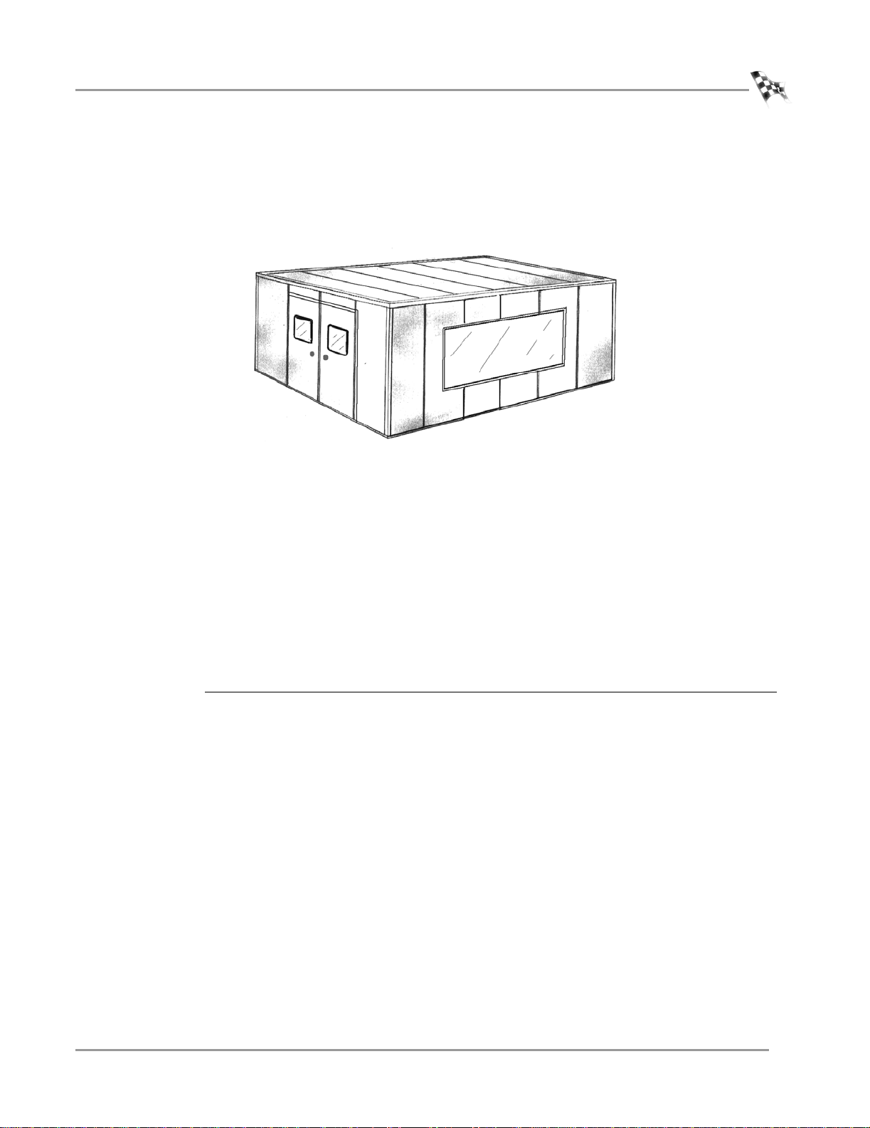
Industrial Noise Control, Inc.—Industrial Noise Control, Inc. offers a zinc-coated
steel room custom built to your specifications. This room meets all dyno room
requirements. For more information on building a dyno room, read the DynoSource
newsletter Volume 1, No. 7 (published by Dynojet) included in your information
pack. The dyno room must be clean, dry, at a minimum of 32 degrees Fahrenheit (0
degrees Celsius), and have some system of exhaust extraction.
Figure 1-1: Custom Dyno Room
12 Volt Battery—A motorcycle starting system is included with your Dynojet
Dynamometer. You will need an automotive battery to use this feature. The dyno is
designed to carry a group 24 deep cycle series battery with a minimum of 600 cold
cranking amps.
Motorcycle Tie-Down Straps—Dynojet recommends using motorcycle tie-down
straps for securing the bike on the dyno. You will need to provide the tie-down straps.
Computer System—You will need to provide a computer system to run the WinPEP
software.
system requirements recommended hardware and software
• Pentium P5-100 processor • Pentium P5-133 or greater processor
• Microsoft® Windows® 9x • 28.8 K modem or better
• 800 MB hard drive • 1.2 gigabyte hard drive or better
• 16 MB of available RAM • 16 MB of available RAM (32 MB for Windows 98)
• 800x600 (SVGA) monitor • 1024x768 (SVGA) monitor
• 16k color video • 16k color video or better
• 8x CD-ROM Drive • 8x CD-ROM Drive
• 8 MB of available hard-disk space is required to install WinPEP
Vers ion 3 Motorcycle Dynamometer Installation Guide
1-3
Page 12
CHAPTER 1
Introduction
CONVENTIONS USED IN THIS MANUAL
The conventions used in this manual are designed to protect both the user and the
equipment.
Example of Convention Description
TECHNICAL SUPPORT
For assistance, please contact Dynojet Technical Support at 1-800-992-3525, or write
to Dynojet at 2191 Mendenhall Drive, North Las Vegas, NV 89031.
Visit us on the World Wide Web at www.dynojet.com where Dynojet provides state of
the art technical support, on-line shopping, 3D visualizations, and press releases
about our latest product line.
The Caution icon indicates a potential hazard to the
dynamometer equipment. Follow all procedures
exactly as they are described and use care when
performing all procedures.
The Warning icon indicates potential harm to the
person performing a procedure and/or the
dynamometer equipment.
1-4
Motorcycle Dynamometer Installation Guide
Page 13
DYNO INSTALLATION AND SETUP
UNCRATE THE DYNO
. . . . . . . . . . . . . . . . . . . . . . . . . . . . . . . . . . .
Use the following steps to uncrate your dyno. You will need to provide equipment
capable of lifting a minimum of 1600 lb. (725 kg.) to move the crated dyno into
position in your dyno room.
1 Move the crated dyno to a clear area near your dyno room.
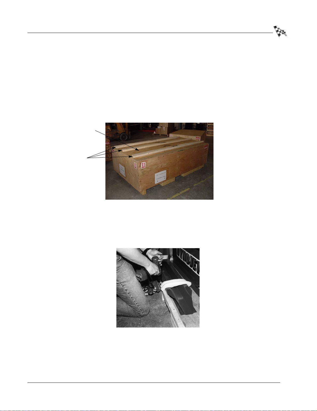
2 Remove the three ramp supports and the ramp face. If you ordered your dyno
without a ramp, skip to step 3.
Refer to “Ramp Assembly” on page 1-14 for ramp assembly instructions,
ramp face
ramp supports
Uncrate the Dyno
Figure 1-2: Remove the Ramp Supports and Face
3 Remove the top and sides of the crate.
3a Use a pry bar, or large flat screwdriver, and a hammer to loosen and remove
the top of the crate.
3b Remove the crate braces and sides.
4 Remove the tire carriage. The tire carriage is fastened to the bottom of the crate.
Figure 1-3: Remove the Tire Carriage from the Crate
Vers ion 3 Motorcycle Dynamometer Installation Guide
1-5
Page 14

CHAPTER 1
Uncrate the Dyno
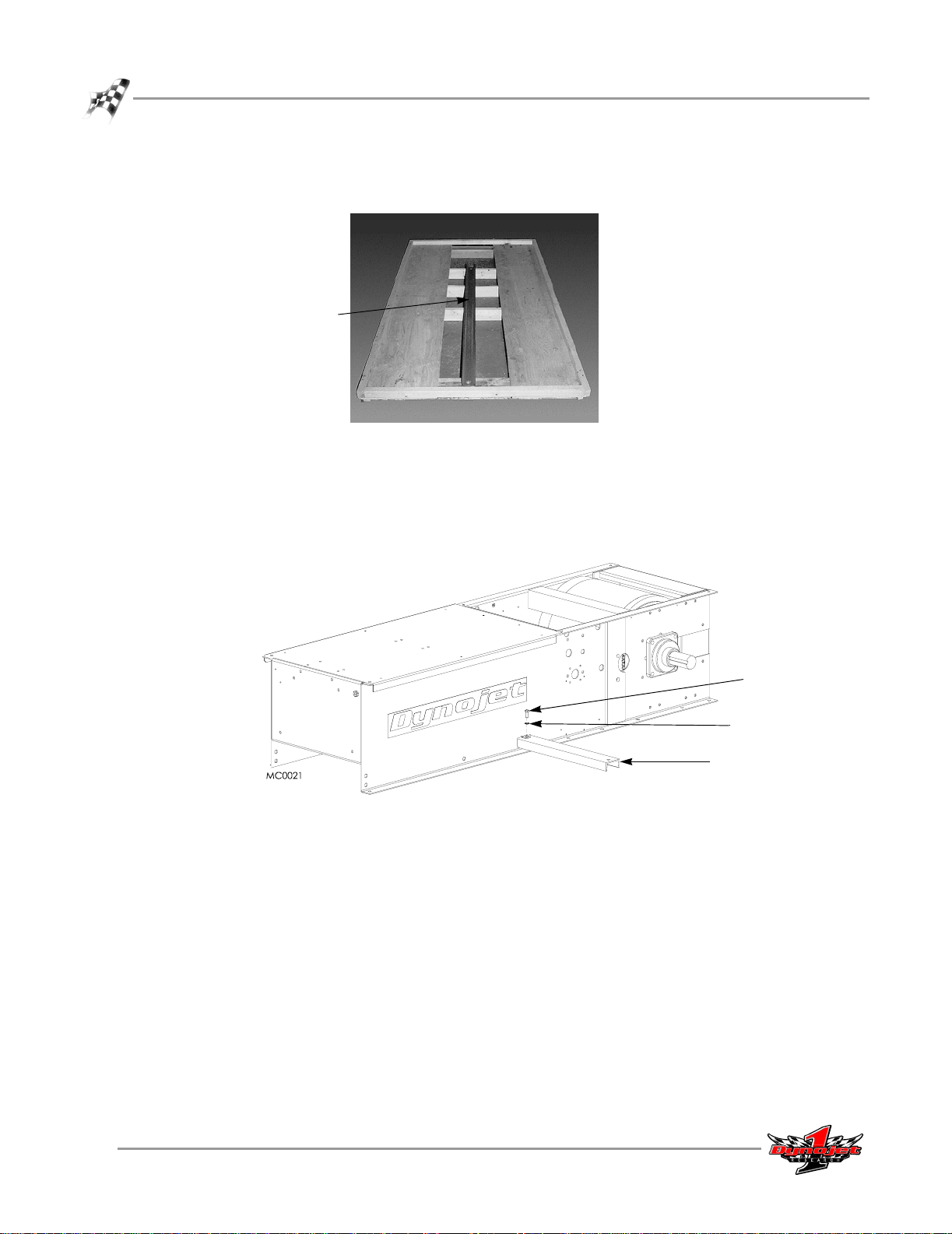
5 Remove the ramp bracket. The ramp bracket is attached to the bottom of the
crate.
Figure 1-4: Remove the Ramp Bracket from the Crate
6 Remove the hardware box containing two outrigger bolts and lock washers, the
tire carriage screw handle, and the screw support bracket. Refer to Figure 1-5.
If you ordered a ramp, the hardware box will also contain six carriage bolts, six
flat washers, six lock washers, and six nuts to be used in the ramp installation.
Refer to “Ramp Assembly” on page 1-14 for ramp assembly instructions,
1-6
Motorcycle Dynamometer Installation Guide
Figure 1-5: Hardware Box Contents
Page 15
REMOVING THE DYNO FROM THE CRATE
You will need to provide equipment capable of lifting a minimum of 1600 lb.
(725 kg.) to lift the dyno off the crate and into position in your dyno room. You will
also need a pair of straps capable of supporting 1600 lb. (725 kg.) to attach to the
dyno. Dynojet recommends using single loop style straps.
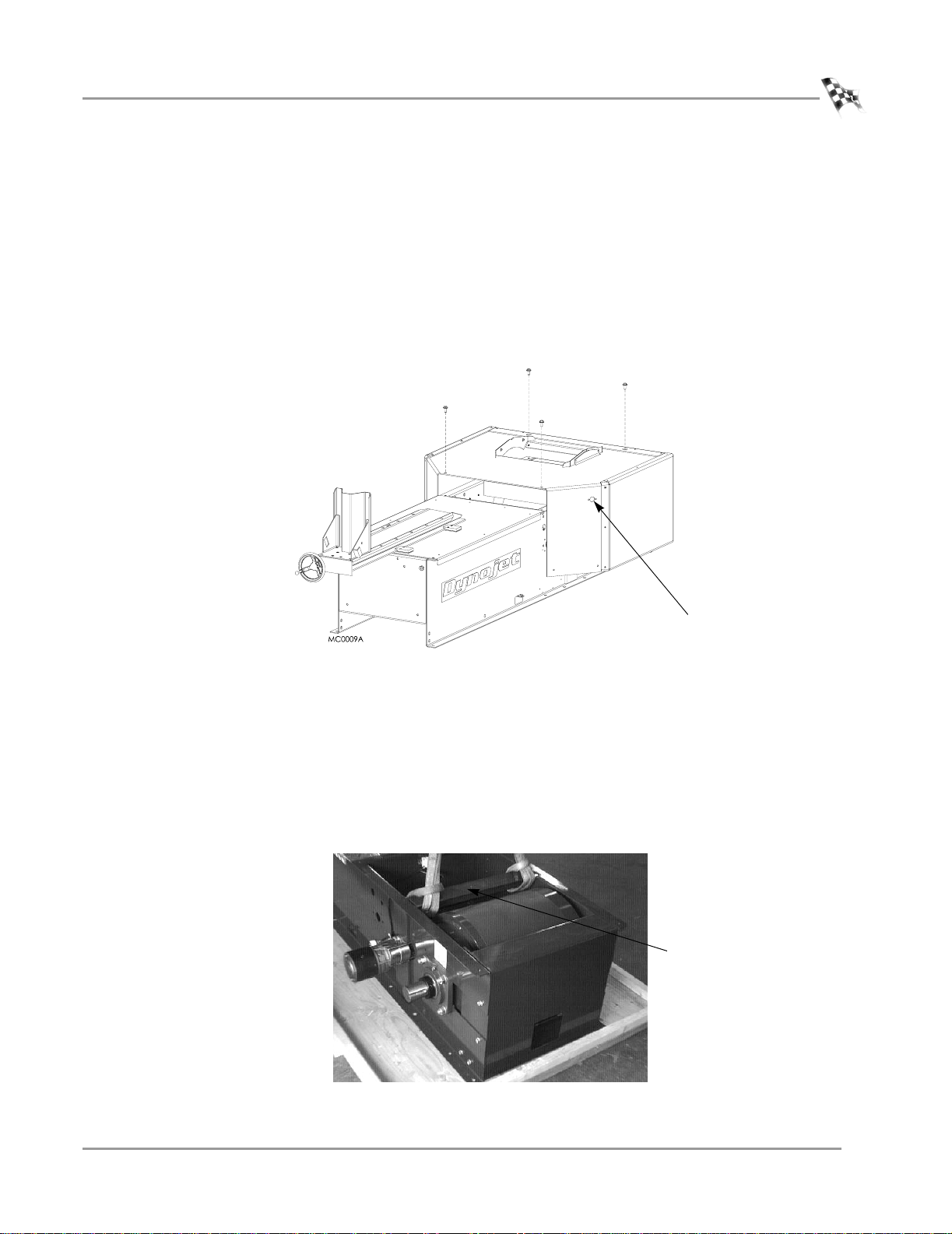
1 Remove the four bolts securing the hood to the dyno and set aside. Prop up the
hood.
2 If present, disconnect the wires to the key switch.
3 Remove the hood from the dyno and set aside.
DYNO INSTALLATION AND SETUP
Uncrate the Dyno
key switch
Figure 1-6: Remove the Hood
4 Remove the four screws securing the dyno to the crate base using a 9/16-inch
socket, open or box end wrench.
5 Wrap the single loop straps around the dyno support frame just in front of the
drum.
6 Position the straps as far to the outside of the support frame as possible. Refer to
Figure 1-7 for exact placement.
Note: Exact placement of the loop straps is important. Any other placement could
damage the dyno.
support frame
in front of drum
Figure 1-7: Loop Strap Placement
Vers ion 3 Motorcycle Dynamometer Installation Guide
1-7
Page 16
CHAPTER 1
Uncrate the Dyno
7 Lift the dyno off the crate and move into position in your dyno room.
8 Remove the metal outrigger attached to the bottom of the crate.
metal outrigger
Figure 1-8: Remove the Metal Outrigger from the Crate
9 Attach the metal outrigger to the dyno. The outrigger is used when strapping the
bike to the dyno.
9a Slide the outrigger through the rectangular hold in the dyno frame.
9b Secure the outrigger to the dyno using two 3/8-inch bolts and lockwashers.
bolt
lock washer
metal outrigger
Figure 1-9: Secure the Metal Outrigger to the Dyno
1-8
Motorcycle Dynamometer Installation Guide
Page 17
DYNO INSTALLATION AND SETUP
TIRE CARRIAGE
. . . . . . . . . . . . . . . . . . . . . . . . . . . . . . . . . . .
The tire carriage is fastened to the bottom of the crate next to the dyno. Refer to
step 4 on page 1-5 for instructions on removing the tire carriage from the crate.
INSTALLING THE TIRE CARRIAGE
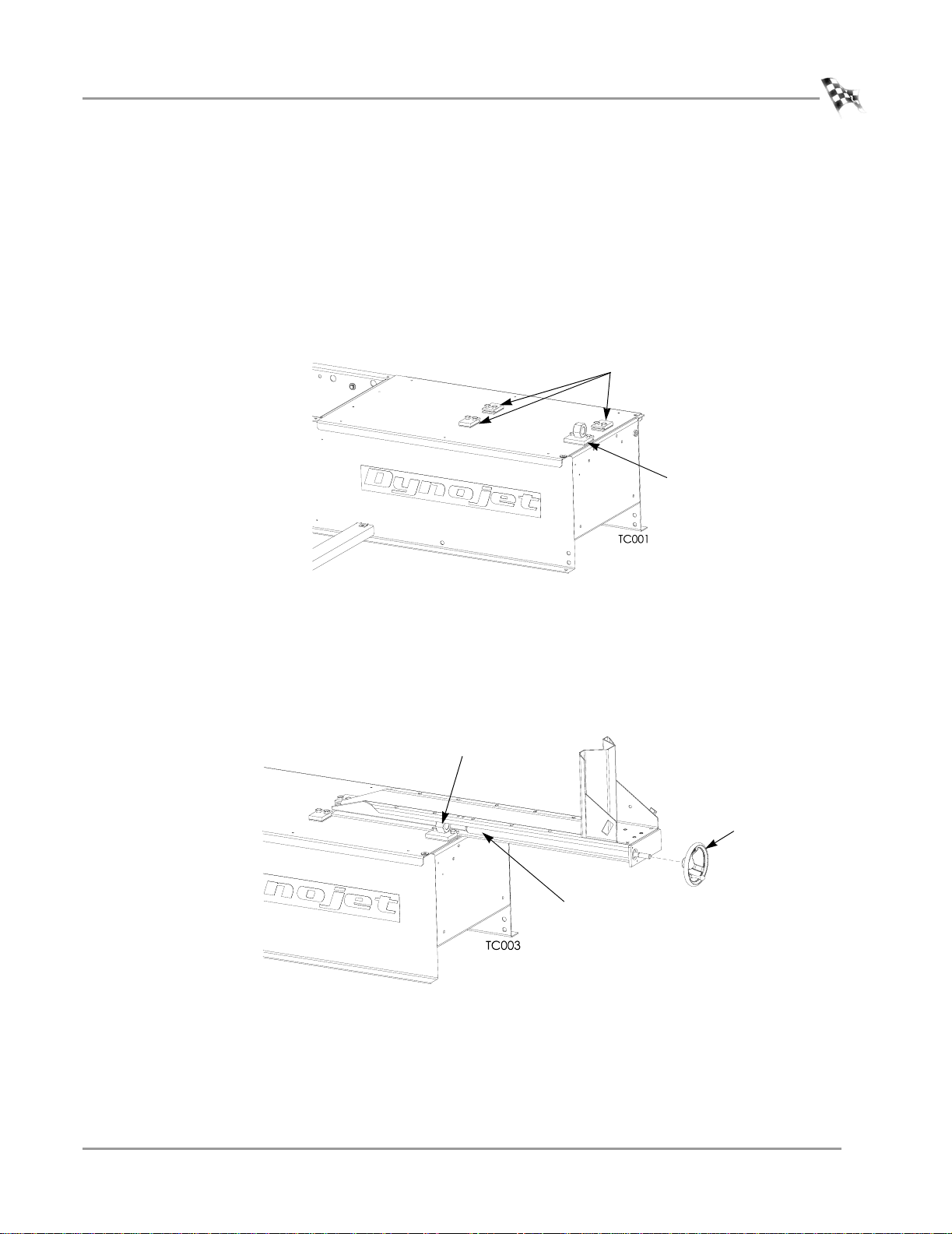
1 Loosen the bolts securing the three carriage clamps and nut block to the top of
the dyno using a 1/2-inch socket, open or box end wrench.
Tire Carriage
carriage clamps
nut block
Figure 1-10: Tire Carriage—Loosen the Clamps and Nut Block
2 Slide the carriage under the carriage clamps and the nut block until the carriage
screw is touching the nut block as shown in Figure 1-11.
3 Slide the hand crank onto the end of the carriage screw.
4 Secure the hand crank to the screw shaft by tightening the set screw using a
5/32-inch allen wrench.
nut block
hand crank
carriage screw
Figure 1-11: Tire Carriage—Secure the Hand Crank
Vers ion 3 Motorcycle Dynamometer Installation Guide
1-9
Page 18
CHAPTER 1
Tire Carriage
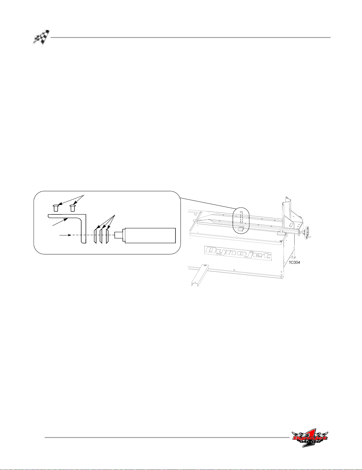
5 Using the hand crank, screw the carriage through the nut block.
6 Install the screw support bracket.
6a Place the belleville washers over the end of the carriage screw. It is
important the belleville washers are installed in the configuration shown in
Figure 1-12.
6b Place the screw support bracket in front of the carriage screw. The two
threaded holes in the bracket should face the two matching holes in the
carriage. Loosely install the two 1/4 x 1/2-inch button-head screws.
6c Before tightening the screws, apply some pressure to the bracket to
compress the belleville washers. The handle should still turn freely, but the
turning force should now be around five to six pounds.
To adjust the force needed to turn the crank handle, adjust the compression
of the belleville washers.
6d Using a 5/32-inch allen wrench, tighten the two button-head screws.
7 Tighten the clamp and nut block bolts with a 1/2-inch wrench.
screws
support
bracket
belleville washers
carriage screw
Figure 1-12: Tire Carriage—Install the Screw Support Bracket
1-10
Motorcycle Dynamometer Installation Guide
Page 19
DYNO INSTALLATION AND SETUP
PICKUP CARD
. . . . . . . . . . . . . . . . . . . . . . . . . . . . . . . . . . .
The pickup card is an electronic circuit board that accurately senses each drum
revolution.
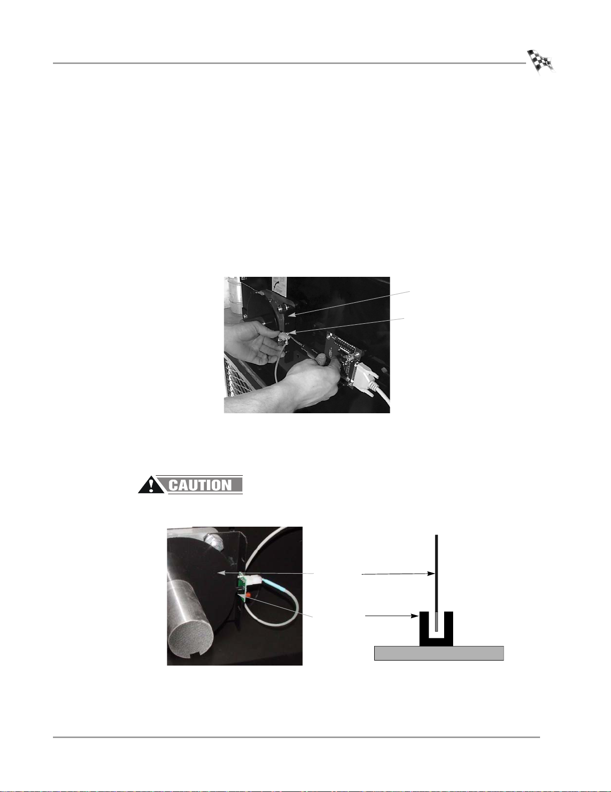
INSTALLING THE PICKUP CARD
1 Locate the pickup card bracket on the right side of the dyno just ahead of the
drum.
2 Install the new pickup card in the notch on the new bracket using two
No. 8 screws and lock washers. Do not tighten, the card must be aligned first
Make sure the side of the card with the optical pickup faces the back of the dyno.
Refer to Figure 1-14.
pickup card
bracket
pickup card
Pickup Card
Figure 1-13: Attach the Pickup Card to the Bracket
3 Align the optical pickup card with the tab on the dyno drum axle. Once aligned,
tighten the screws to secure the pickup card in place.
The optical pickup is very delicate. Be careful not to damage the optical pickup
during alignment.
tab on dyno
optical pickup
Figure 1-14: Align the Pickup Card
Vers ion 3 Motorcycle Dynamometer Installation Guide
1-11
Page 20
CHAPTER 1
Battery
BATTERY
. . . . . . . . . . . . . . . . . . . . . . . . . . . . . . . . . . .
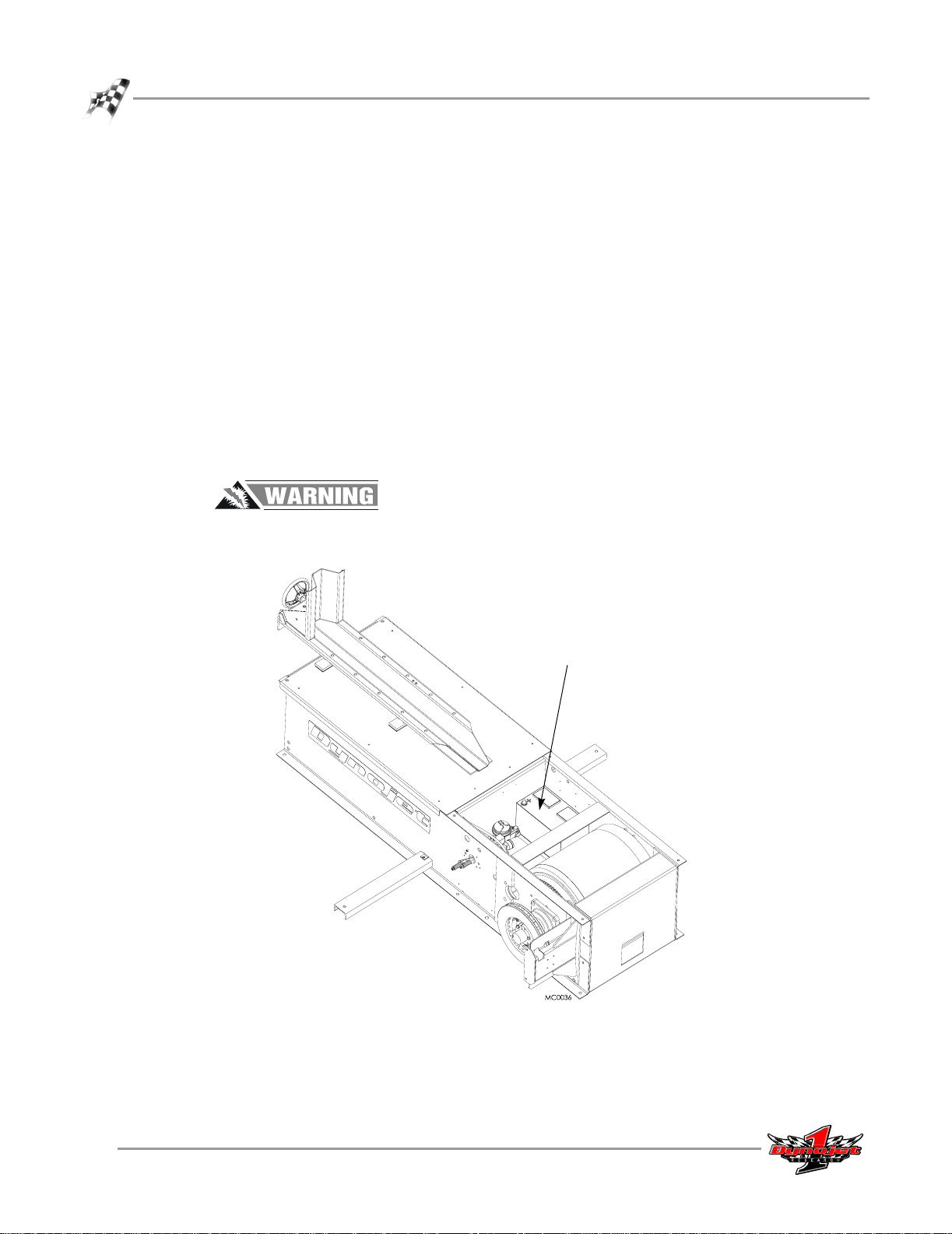
A bike starting system is included with your Dynojet Dynamometer. You will need to
provide an automotive battery to use this system. The dyno is designed to carry a
group 24 series battery with a minimum of 600 cold cranking amps.
INSTALLING THE BATTERY
1 Locate the red battery cable on the inside of the dyno.
2 Place the battery in the battery carrier on the inside of the dyno so the red cable
can reach the positive (+) post on the battery and the black battery cable can
reach the negative (-) post.
3 Secure the red battery cable to the positive (+) battery post.
4 Secure the black battery cable to the negative (-) battery post.
5 Press the starter button to verify that the starter turns the drum correctly.
To prevent possible injury, disconnect the battery before performing any dyno
maintenance or installing any optional accessories.
battery with positive side
towards the front of the dyno
Figure 1-15: Install the Battery
1-12
Motorcycle Dynamometer Installation Guide
Page 21

DYNO INSTALLATION AND SETUP
DYNO HOOD
. . . . . . . . . . . . . . . . . . . . . . . . . . . . . . . . . . .
There is a door safety switch included with the European dynos only. European dyno
owners will need to install this switch before reinstalling the hood. Installation
instructions are included with the switch.
INSTALLING THE HOOD
1 Make a final inspection of your dyno and verify that all connections are tight.
2 If you have not already done so, connect the battery.
3 Carefully place the hood on the dyno leaving it propped up.
4 Secure the wires to the key switch.
Note: You must have the wires connected and the key installed to operate the
dyno. The orientation of the wires on the key switch is not important.
5 Lower and secure the hood using the four bolts you removed earlier.
Never operate the dyno with this cover removed.
Dyno Hood
key switch
Figure 1-16: Secure the Hood to the Dyno
Vers ion 3 Motorcycle Dynamometer Installation Guide
1-13
Page 22
CHAPTER 1
Ramp Assembly
RAMP ASSEMBLY
. . . . . . . . . . . . . . . . . . . . . . . . . . . . . . . . . . .
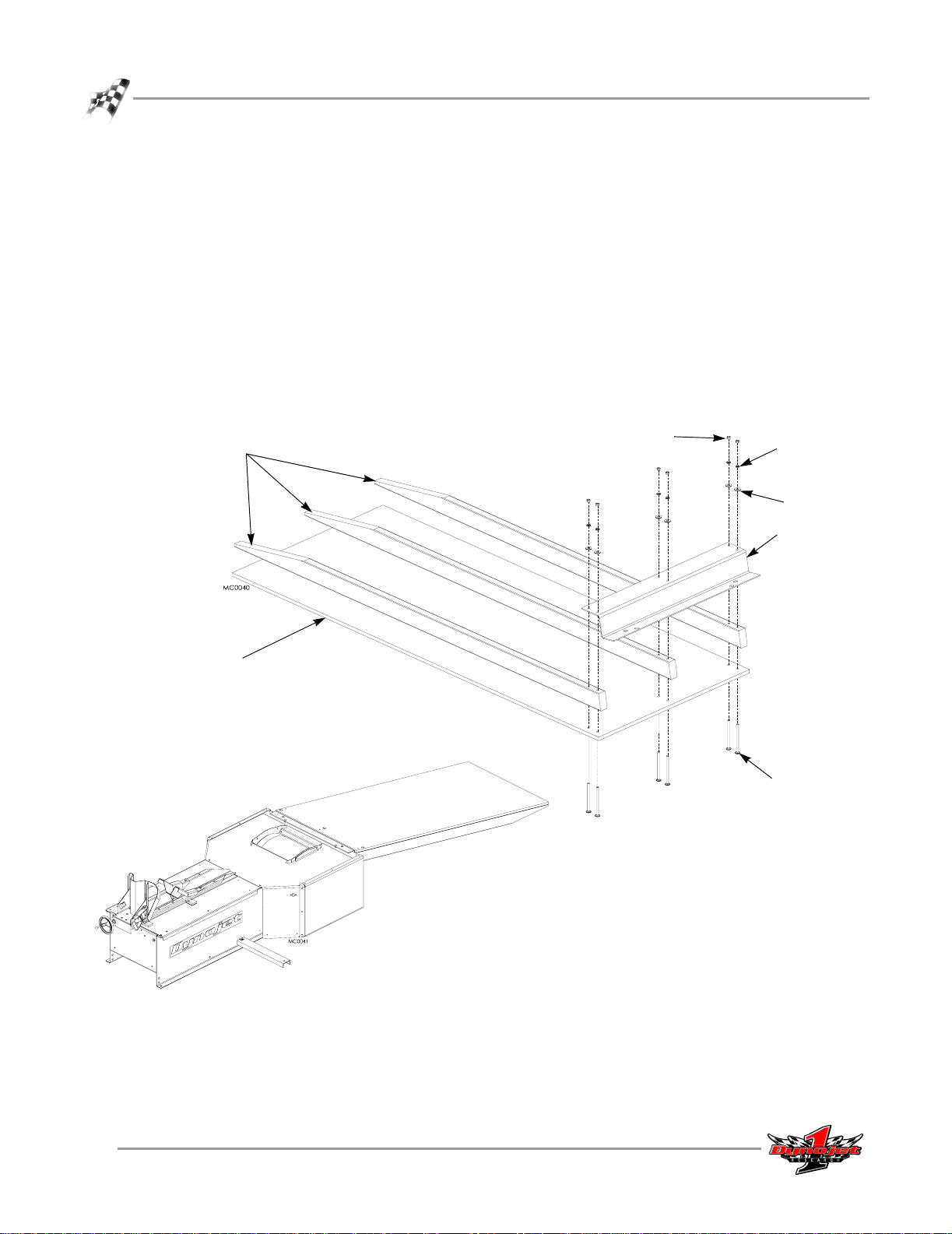
The ramp is assembled by bolting the ramp face, the ramp supports, and the ramp
bracket together.
Note: You will need to supply additional wood screws or nails to secure the ramp
supports to the ramp face.
1 Using the ramp bracket as a template, mark and drill six holes in the ramp face
using a 3/8-inch bit.
2 Secure the ramp face, supports, and bracket using six six-inch carriage bolts, six
flat washers, six lock washers, and six nuts.
3 Make sure the supports are aligned properly with the ramp face and secure the
supports to the ramp face using wood screws or nails.
nut
ramp support
lock washer
flat washer
ramp bracket
ramp face
carriage bolt
Figure 1-17: Ramp Assembly
1-14
Motorcycle Dynamometer Installation Guide
Page 23

ELECTRICAL DIAGRAM
DYNO INSTALLATION AND SETUP
Electrical Diagram
Figure 1-18: Electrical Diagram
Vers ion 3 Motorcycle Dynamometer Installation Guide
1-15
Page 24

CHAPTER 1
Electrical Diagram
1-16
Motorcycle Dynamometer Installation Guide
Page 25

C HAPTER
2
H
ARDWARE INSTALLATION
This chapter contains the hardware installation specifications for the DynoWare EX+
modules.
This chapter is divided into the following categories:
• Dynoware EX+ Hardware Stack, page 2-2
• Atmospheric Sensing Module, page 2-2
•RPM Module, page 2-3
• Dynamometer Input/Output Module, page 2-4
• CPU Module, page 2-5
• Connecting the DynoWare EX+ Cables, page 2-6
Motorcycle Dynamometer Installation Guide
2-1
Page 26

CHAPTER 2
Dynoware EX+ Hardware Stack
DYNOWARE EX+ HARDWARE STACK
. . . . . . . . . . . . . . . . . . . . . . . . . . . . . . . . . . .
The standard dynamometer electronics package (hardware stack) is comprised of four
interconnected modules: Atmospheric Sensing Module, RPM Module, Dynamometer
Input/Output Module, and the CPU Module.
system expansion
connector
atmospheric
sensing module
RPM module
dynamometer
input/output module
CPU module
Figure 2-1: Dynoware EX+ Hardware Stack
ATMOSPHERIC SENSING MODULE
The atmospheric sensing module measures absolute pressure, air temperature, and
relative humidity. These measurements are used by WinPEP to correct power and
torque measurements to standard atmospheric conditions according to a DIN, SAE, or
other formula.
LED Indicator Description
The green LED glows when the atmospheric sensing
module is receiving power.
The flashing amber LED indicates the module processor
is operating properly.
2-2
Motorcycle Dynamometer Installation Guide
Page 27

RPM MODULE
The RPM module receives and processes signals from up to two inductive pickups for
measurement of engine RPM. Each input has an automatic gain circuit to compensate
for a wide variance of ignition systems.
LED Indicator Description
HARDWARE INSTALLATION
Dynoware EX+ Hardware Stack
Figure 2-2: RPM Module
The green LED glows when the RPM module is receiving
power.
The amber LED flashes when an RPM signal is detected.
A steady flash rate, proportional to engine RPM, indicates
a good RPM signal.
These connectors are the inputs for both primary and
secondary inductive pickup clips. Either input may be
used with a primary inductive pickup or a secondary
inductive pickup on a single ended coil. Both inputs can
be used for a wasted spark ignition.
Vers ion 3 Motorcycle Dynamometer Installation Guide
2-3
Page 28

CHAPTER 2
Dynoware EX+ Hardware Stack
DYNAMOMETER INPUT/OUTPUT MODULE
The dynamometer input/output module sends and receives data from the
dynamometer and the hand-held pendant. The module also contains a buzzer and
light which are activated when either the vehicle or the dynamometer speed limit is
approached.
Figure 2-3: Dynamometer Input/Output Module
LED Indicator Description
The green LED glows when the dynamometer
input/output module is receiving power.
The amber LED flashes proportionally to dynamometer
drum RPM.
This 25-pin connector attaches to the shielded cable from
the dynamometer.
This 9-pin connector attaches to the hand held pendant
which houses the button used to start/stop acquiring
data. The pendant may also contain a brake switch.
2-4
Motorcycle Dynamometer Installation Guide
Page 29

CPU MODULE
The CPU module contains a 32-bit processor which acquires data from the expansion
modules and communicates to the main computer running the WinPEP software. The
processor queries the expansion modules to determine their identity and capabilities.
LED Indicator Description
HARDWARE INSTALLATION
Dynoware EX+ Hardware Stack
Figure 2-4: CPU Module
The green LED glows when the CPU module is receiving
power.
The blue LED is lighted when data from the modules is
being acquired and saved.
One of these connectors is used to communicate to the
main computer. The 9-pin connector (left) attaches to
the PC’s RS-232 serial communications port. The 8-pin
modular connector (right) provides communications
according to the RS-422/485 specification.
This connector provides a synchronization signal to a
third party data acquisition system.
This connector provides 12 volt DC power to a third
party data acquisition system.
This connector accepts 12 volt DC power from a power
supply or battery. The adjacent LED glows bright green
when power is properly connected.
When this switch is on, power is supplied to all
connected modules.
Vers ion 3 Motorcycle Dynamometer Installation Guide
2-5
Page 30

CHAPTER 2
Dynoware EX+ Hardware Stack
CONNECTING THE DYNOWARE EX+ CABLES
Attach the following cables using the cables that came in the DynoWare package. Refer
to Figure 2-5 for cable placement locations.
• Attach the 9-pin shielded serial cable to the RS-232 socket on the CPU module and
a free COM (serial communications) port on the PC. A 9-pin to 25-pin adapter may
be required at the PC.
• Attach the 25-pin shielded cable from the dynamometer to the Dynamometer
Input/Output module.
• Attach the 9-pin connector from the hand-held pendant to the Dynamometer
Input/Output module.
• Attach the 3-pin plug from the power supply to the CPU module with the flat side
facing down.
Note: The DynoWare EX+ hardware stack must be mounted in your shop so as to
be easily seen while making dyno runs.
primary inductive
pickup socket
25-pin socket
9-pin, RS-232 socket
9-pin, hand help
pendant
3-pin power plug
Figure 2-5: Connecting the Dynoware EX+ Cables
2-6
Motorcycle Dynamometer Installation Guide
Page 31

O
PTIONAL
C HAPTER
A
CCESSORIES
3
This chapter discusses the various optional accessories that are available for the
Dynojet Dynamometer (dyno). For more information about these accessories, please
contact Dynojet’s Product Specialist’s at 1-800-992-3525 for pricing and availability.
This chapter is divided into the following categories:
• Optional Accessories Overview, page 3-2
• Removing and Replacing the Hood, page 3-3
•Air Brake, page 3-4
• Dual Fan, page 3-17
• Extended Carriage, page 3-24
• Mechanical Brake, page 3-29
• Monitor Arm, page 3-34
• Power Carriage, page 3-37
Motorcycle Dynamometer Installation Guide
3-1
Page 32

CHAPTER 3
Optional Accessories Overview
OPTIONAL ACCESSORIES OVERVIEW
. . . . . . . . . . . . . . . . . . . . . . . . . . . . . . . . . . .
Depending on your current configuration, there are various optional accessories that
can be added to your Dynojet Dynamometer to meet your individual needs. All of
these options can be added from the factory at the time of original dyno purchase, or
purchased separately and added at any time thereafter. A brief description of these
accessories follows.
Installation instructions for some of these options can be found in this chapter.
Complete installation instruction manuals may also be found by browsing the
Manuals folder on your WinPEP installation CD.Visit the Dynojet web site for more
information about dynamometer accessories and ordering information.
Air or Mechanical Brake—The air brake is an electro-pneumatic braking system
while the mechanical brake is a foot actuated hydraulic brake. Both brakes can be
utilized to quickly slow the drum after a run is complete. This is especially useful for
two-stroke applications when engine compression cannot be used to slow the drum.
Both brakes can greatly speed up the testing process. Refer to “Air Brake” on page 3-4
or “Mechanical Brake” on page 3-29 for installation instructions.
Dual Fan—The dual fan supplies air to cool the bike’s engine. Refer to “Dual Fan” on
page 3-17 for installation instructions.
Eddy Current Brake— The eddy current brake is perfect for engine break-in,
durability testing, and fuel injection mapping. Refer to your WinPEP CD for
installation instructions.
Extended Carriage—The extended carriage option increases the maximum wheel
base (measured from the front of the front wheel to the center of the rear wheel) from
84 inches to 102 inches for testing raked cruisers and drag bikes. Refer to “Extended
Carriage” on page 3-24 for installation instructions.
Fat Boy Adapter—The Fat Boy adapter is necessary when strapping a HarleyDavidson Fat Boy, or any other bike with a solid front wheel, to the carriage of the
dyno. Adapter includes a second ratchet, ratchet strap, double-hook strap, and
necessary fastening hardware. Refer to your WinPEP CD for installation instructions.
High Inertia Drum—The high inertia drum is suggested when testing bikes that
produce more than 250 horsepower at the rear wheel. The extra inertia built into this
special drum adjusts the run time to be equivalent to that of a standard drum with an
average-power motorcycle.
Mobile Base—The mobile base is essential for shops that require maximum flexibility
and mobility. The mobile base allows the dyno to be relocated in a matter of minutes.
Refer to your WinPEP CD for installation instructions.
Monitor Arm—This articulated arm and platform supports the monitor, keyboard,
and mouse in a convenient position for operation while seated on the motorcycle.
Refer to “Monitor Arm” on page 3-34 for installation instructions.
3-2
Motorcycle Dynamometer Installation Guide
Page 33

OPTIONAL ACCESSORIES
Optional Accessories Overview
Power Carriage—The power carriage replaces the standard hand crank with an
electrically powered tire carriage allowing you to easily adjust for various wheel base
distances with the press of a button. This option is ideal for dynos that are recessed
where the hand crank is difficult to access. The power carriage will also reduce the
time spent making adjustments for various length motorcycles. Refer to “Power
Carriage” on page 3-37 for installation instructions.
RPM Pickup—The secondary RPM pickup attaches to a spark plug wire to acquire an
RPM signal for the hardware stack.
Trailer Package—The trailer package is a simple and attractive way to make your
dyno portable. Each bolt-on kit includes independent suspension, tires, fenders, tow
hitch, lights, and a license plate bracket. The trailer package is not available for model
250 dynos. Refer to the WinPEP CD for installation instructions.
REMOVING AND REPLACING THE HOOD
Many of the procedures and instructions in this chapter require you to remove and
replace the hood. Refer to the following steps for removing and replacing the hood.
1 Remove the hood.
1a Remove the four bolts securing the hood to the dyno and set aside. Prop up
the hood.
1b If present, disconnect the wires to the key switch.
1c Remove the hood from the dyno and set aside.
1d Disconnect all battery wires.
2Replace the hood.
2a Connect the battery.
2b Carefully place the hood on the dyno, leaving it propped up.
2c Secure the wires to the key switch, if present.
2d Lower and secure the hood using the four bolts removed earlier.
key switch
Figure 3-6: Remove and Replace the Hood
Vers ion 3 Motorcycle Dynamometer Installation Guide
3-3
Page 34

CHAPTER 3
Air Brake
AIR BRAKE
. . . . . . . . . . . . . . . . . . . . . . . . . . . . . . . . . . .
The air brake is an electro-pneumatic braking system and includes a two button
pendent. The air brake can be utilized to quickly slow the drum after a run is
complete. This is especially useful for two-stroke applications when engine
compression cannot be used to slow the drum. The air brake can also greatly speed
up the testing process.
When upgrading from a mechanical brake, you will no longer use the sample button;
you will need to use the new two button pendant (P/N DC100-104). The new pendant
attaches to the same nine-pin terminal on your hardware stack.
If you purchased your dyno with an air brake assembly, the air brake will already be
installed. You will need to provide an air hose nipple to connect your shop air supply
(80 psi constant line pressure) to the dynamometer. Once air pressure is connected,
the air brake is ready to use.
connect shop air supply
Figure 3-7: Connect Your Shop Air Supply
To prevent possible injury, disconnect the battery before performing any dyno
maintenance or installing any optional accessory.
3-4
Motorcycle Dynamometer Installation Guide
Page 35

OPTIONAL ACCESSORIES
PARTS LIST
The following table lists all of the parts included in the Air Brake (P/N 102-201)
Installation kit. Check your kit against the parts listed to make sure you have received
all of the parts. If any part is missing, contact Dynojet Technical Support.
part number description quantity
197104130 Zip Tie, 4” 6
22103080 Rod, Air Brake Spring 2
22923000 Spring Guide (retainer ring) 4
36390640 Bolt, 1/2-20 x 3/4, Hex 1
43310600 Grommet, 7/16” ID x 3/4” OD 1
61322300 Spring Bolt Mounting Plate 1
63990001 Caliper Assembly 1
63990002 Rotor/Taper Lock Assembly with Hub and Key 1
63990004 Air Cylinder Assembly 1
BR102-033 Grommet, 1”OD, 3/8ID, 3/4H, 1/8G 1
Air Brake
BR102-038-5 Air Hose Push Lock Fitting 1
BR102-038-6 Air Hose Bulk Head Fitting 1
BR102-038-7 Air Hose, 55” .05 55.00 inches
BR102-041 Master Cylinder 1
BR102-045 Brake Hose (installed) 1
None Copper Washers (installed) 2
BR102-046 Brake Line 1
BR102-047 Banjo Bolt (installed) 1
BR102-055 Springs, Purple (for Spring Bolt Assembly) 2
BR102-061 Bolts, 1/4 x 4 1/2”, Socket Head 2
DC100-104 Pendant and Cable 1
DE100-134 Screw, 8 x 1/2”, Self Tapping 2
DM150-035 1/2” Cable Clamp, Nylon 2
DM150-009-005 Nut, 1/4”, Adjuster (for Spring Bolt Assembly) 4
Vers ion 3 Motorcycle Dynamometer Installation Guide
3-5
Page 36

CHAPTER 3
Air Brake
INSTALLING THE ROTOR/TAPER LOCK ASSEMBLY
When upgrading from a manual brake, the rotor/taper lock assembly and caliper
assembly will already be installed. Proceed to “Installing the Air Cylinder and Master
Cylinder Assembly” on page 3-8.
1 Insert the key into the slot on the shaft.
2 Slide the rotor/taper lock assembly on to the shaft.
key
shaft
rotor/taper lock
assembly
Figure 3-8: Install the Rotor/Taper Lock Assembly
3 Attach the dial indicator to the side of the dyno. Spin the drum and check for run
out; the tolerances are +/- .005".
4 Tighten the taper lock bolts. While tightening, adjust the bolts to keep the run out
within tolerances. Torque the taper lock bolts to 15 ft. lb.
dial indicator
taper lock bolts
(two visible here)
Figure 3-9: Check for Run Out
3-6
Motorcycle Dynamometer Installation Guide
Page 37

INSTALLING THE CALIPER ASSEMBLY
1 Tighten the two bolts shown in Figure 3-39.
2 Remove the four bolts and washers in the top and bottom right corners (as shown
in Figure 3-10) and set aside. These bolts will be used to mount the caliper
assembly in step 3.
OPTIONAL ACCESSORIES
Air Brake
remove bolts and use to
mount caliper assembly
tighten
remove bolts and use to
mount caliper assembly
Figure 3-10: Caliper Assembly Mounting Bolts
3 Secure the caliper assembly with the four bolts and washers removed in step 2.
caliper assembly
Figure 3-11: Secure the Caliper Assembly
Vers ion 3 Motorcycle Dynamometer Installation Guide
3-7
Page 38

CHAPTER 3
Air Brake
4 Adjust the space between the brake pad and the rotor making sure the rotor is
able to spin free of contact.
Loosen the jam nut and use the adjuster nut to move the brake pads in or out.
jam nut
Figure 3-12: Adjust the Brake Pad Space
adjuster nut
INSTALLING THE AIR CYLINDER AND MASTER CYLINDER ASSEMBLY
1 With the air cylinder on the inside of the dyno frame and the mounting plate on
the outside, secure the air cylinder with the 1/2-20 x 3/4-inch bolt.
cut away view of
dyno side panel
air cylinder
3-8
Motorcycle Dynamometer Installation Guide
bolt
mounting plate
Figure 3-13: Install the Air Cylinder
Page 39

OPTIONAL ACCESSORIES
Air Brake
2 Slide the master cylinder assembly through the holes in the air cylinder and
through the dyno frame.
3 Secure the master cylinder to the air cylinder with two 1/4 x 4 1/2-inch socket
head mounting bolts using a 3/16-inch allen wrench.
cut away view of dyno
side panel
master cylinder
bolts
air cylinder
Figure 3-14: Install the Master Cylinder
4 Run the metal brake line from the master cylinder to the caliper brake hose.
4a Insert a rubber grommet into the hole shown in Figure 3-15.
4b Run the brake line from the master cylinder through the grommet and over
to the caliper assembly.
4c Secure the brake line to the master cylinder and to the caliper brake hose.
4d Secure the brake line to the outside of the dyno frame using two nylon
loops and two 8 x 1/2-inch self tapping screws.
grommet
master
cylinder
grommet
metal brake line
nylon loops
secure metal brake line
to caliper brake hose
brake
hose
metal brake line
Figure 3-15: Install the Metal Brake Line
Vers ion 3 Motorcycle Dynamometer Installation Guide
3-9
Page 40

CHAPTER 3
Air Brake
INSTALLING THE SPRING BOLT ASSEMBLY
1 Push the mounting plate flush with the dyno cabinet.
2 Install the rear retainer, spring, front retainer, and adjuster nut. Be sure the
hardware is in this order.
Note: You may need to compress the spring to get the adjuster nut on.
The distance from the front retainer to the dyno cabinet should be 3.25 inches.
Final adjustments will be made later.
If the distance is less that 3.25 inches, us a flat blade screwdriver to unscrew the
spring rod until the proper distance is achieved.
3 Turn the adjuster nut to tighten the spring until there is enough room on the
spring rod for the jam nut.
4 While holding the adjuster nut from turning, tighten the jam nut against the
adjuster nut.
cut away view of dyno
side panel
hold adjuster nut
tighten jam nut
against adjuster nut
dyno cabinet
front retainer
mounting plate
front retainer
adjuster nut
3-10
Motorcycle Dynamometer Installation Guide
spring rod
jam nut
spring
rear retainer
Figure 3-16: Install the Spring Bolt Assembly
Page 41

INSTALLING THE AIR HOSE
1 Install the 1-inch grommet into the hole shown in Figure 3-17.
2 Wrap the push lock fitting with thread tape. Refer to Figure 3-18.
3 Insert the five foot section of air hose through the hole. Leave enough air hose
exposed and attach it to the regulator.
attach air hose to
regulator
OPTIONAL ACCESSORIES
Air Brake
run air hose
inside dyno
grommet
Figure 3-17: Secure the Air Hose to the Regulator
Vers ion 3 Motorcycle Dynamometer Installation Guide
3-11
Page 42

CHAPTER 3
Air Brake
4 Lift the front of the dyno high enough to access the cut out on the bottom side of
the dyno.
The dyno is heavy. Use suitable methods to lift and support the dyno while
working through these steps.
5 Reach into the access hole in the bottom of the dyno and find the air hose.
6 Place the nut and washer from the bulk head fitting onto the air hose.
7 Insert the air hose through the hole in the front dyno panel and thread the bulk
head fitting onto the push lock fitting.
8 Insert the bulk head fitting into the hole. While holding the bulk head fitting from
the outside, tighten the nut from the inside.
Note: You will need to supply the couplers/fittings to attach to the bulk head
fitting. Using a quick coupler at the end is convenient if you need that air source
for other activities in the shop.
air hose
(inside dyno)
cut away view of
front dyno panel
bulk head fitting
(outside dyno)
push lock fitting
bulk head fitting
nut
washer
push lock fitting
with thread tape
install complete
Figure 3-18: Install the Bulk Head Fitting
3-12
Motorcycle Dynamometer Installation Guide
Page 43

WIRING THE AIR VALVE ASSEMBLY
The wires that attach to the air valve assembly can be attached in two different places
depending on your dyno’s set up. Wire Set Up 1 is generally for older dynos while
Wire Set Up 2 is for newer dynos.
WIRE SET UP 1
This wire set up is used in older dynos that have an exposed (not in a black box)
terminal strip with only eight terminals. If your terminal strip is in a box and has
sixteen terminals, refer to Wire Set Up 2 on page 14.
1 Attach the air hose to the coupler and adjust the regulator to 80 psi.
2 Run the two black wires from the air valve to the top two terminals on the left
side, refer to Figure 3-19.
3 Wire the two black extension leads to the top two terminals on the right side.
OPTIONAL ACCESSORIES
Air Brake
black leads from
the air valve
Figure 3-19: Wire Set Up 1—Terminal Strip Wiring
4 Remove the four screws securing the Breakout board and cover. Set the screws
and cover aside.
5 Attach the extension leads to the Breakout board. Orientation of the wires is not
important.
6 Replace the Breakout board cover using the four screws removed earlier.
two black terminal
strip wires
extension leads to
the Breakout board
Breakout board
and cover
Figure 3-20: Wire Set Up 1—Breakout Board Wiring
Vers ion 3 Motorcycle Dynamometer Installation Guide
3-13
Page 44

CHAPTER 3
Air Brake
WIRE SET UP 2
This wire set up is used in newer dynos where the terminal strip is housed in a black
box and has sixteen terminals. If your terminal strip is not in a box and has only eight
terminals, refer to Wire Set Up 1 on page 13.
1 Attach the air hose to the coupler and adjust the regulator to 80 psi.
2 Remove the cover from the black box.
3 Run the wires from the air valve through the hole on the side of the black box.
4 Attach the air valve wires to the terminal strip as shown in Figure 3-21. The black
and yellow leads for the Breakout board have been pre wired to the terminal strip
at Dynojet.
hole
air valve wire
Figure 3-21: Wire Set Up 2—Terminal Strip Wiring
5 Secure the cover to the black box.
6 Remove the four screws securing the Breakout board and cover. Set the screws
and cover aside.
7 Attach the black and yellow leads from the terminal strip to the Breakout board.
Orientation of the wires is not important.
8 Verify the jumper settings on the Breakout board.
9 Replace the Breakout board cover using the four screws removed earlier.
yellow
black
air valve wire
black and yellow leads
to breakout board
Breakout board
and cover
Figure 3-22: Wire Set Up 2—Breakout Board Wiring and Jumper Settings
3-14
Motorcycle Dynamometer Installation Guide
Page 45

FINAL ADJUSTMENTS AND TESTS
1 Verify the dyno is set up properly, the hardware stack is powered up and
operational, and the air supply is connected properly.
2 Verify the brake is off; the red light on the pendant should be off.
3 Fill the master cylinder with DOT 5 brake fluid.
4 Open the bleeder valve on the caliper assembly and use the red brake button on
the pendant to activate the brake. You should see fluid and air being purged from
the bleeder valve. Repeat this procedure until the system is completely bled.
5 If you find you are not getting sufficient brake performance, adjust the spring rod
nuts to increase the spring pressure.
5a Loosen the jam nut.
5b Place the jam nut flush with the end of the spring rod and insert a
screwdriver into the slot on the end of the spring rod.
5c Tighten the adjuster nut until the springs begin to overcome the force of the
air pushing against them.
5d Once the adjuster nut is in place, snug the jam nut up to the adjuster nut.
5e Test the brake several more times to verify the brake pads return far enough
to clear the rotor.
6 Use the red brake button on the pendant to activate and deactivate the brake.
Listen for air leaks and double check all connections.
7 Adjust the clearance between the pads and the rotor by loosening the jam nut and
turning the adjuster nut on the caliper assembly. There should be equal space on
both sides of the rotor. Refer to Figure 3-41 for more information on the caliper
assembly jam and adjuster nuts.
Note: Cycle the brake to verify the brake pads release far enough and do not
touch the rotor. If the pads touch the rotor during a run, the information
provided by the dyno will be inaccurate.
8 Replace the hood. Refer to “Removing and Replacing the Hood” on page 3-3.
OPTIONAL ACCESSORIES
Air Brake
Vers ion 3 Motorcycle Dynamometer Installation Guide
3-15
Page 46

CHAPTER 3
Air Brake
AIR BRAKE ASSEMBLY SCHEMATIC
3-16
Motorcycle Dynamometer Installation Guide
Figure 3-23: Air Brake Assembly Schematic
Page 47

OPTIONAL ACCESSORIES
DUAL FAN
. . . . . . . . . . . . . . . . . . . . . . . . . . . . . . . . . . .
The dual fan supplies air to cool the bike’s engine. This section will walk you through
the fan installation procedures and adjusting the extension arm assembly when a
power carriage is installed.
The fan extension arm assembly comes ready to mount to the tire carriage on the
dyno. However, if you have a power carriage installed on your dynamometer, you will
need to make adjustments to the extension arm assembly before mounting the
assembly to the dyno. Refer to “Modifying the Extension Arm Assembly (For Power
Carriage Only)” on page 3-22.
To prevent possible injury, disconnect the battery before performing any dyno
maintenance or installing any optional accessory.
PARTS LIST
The following table lists all of the parts included in the Dual Fan Installation kit.
Check your kit against the parts listed to make sure you have received all of the parts.
If any part is missing, contact Dynojet Technical Support.
Dual Fan
part number description quantity
76722001
Or
76722002
63413002 Dual Fan Mounting Bracket and Extension Arm Assembly 1
26215520 Washer, 1.87 x 1.25 IDx .12Thk (Poly Washer) 2
36582477 Bolt, 3/8"-16 x 1-1/2", Hex 4
36488100 Nut, 3/8"-16, Nylock 4
36932100 Washer, 3/8", Splitlock, Stl 4
DE100-311 &
21629100
Dual Fan Assembly (complete assembly)
Or
Dual Fan Assembly-220V (complete assembly)
Outlet Box and Mounting Bracket 1
1
Vers ion 3 Motorcycle Dynamometer Installation Guide
3-17
Page 48

CHAPTER 3
Dual Fan
MODIFYING THE TIRE STOP
Older dynos may not have the four holes on the tire stop needed to mount the
extension arm assembly; you will need to modify the tire stop before continuing with
the fan installation instructions. Refer to Figure 3-24 for hole size and placement.
3-18
Motorcycle Dynamometer Installation Guide
Figure 3-24: Modify the Tire Stop
Page 49

INSTALLING THE EXTENSION ARM ASSEMBLY
The fan extension arm assembly comes ready to mount to the tire stop on the dyno.
Note: If you have a power carriage installed on your dyno, you will need to make
adjustments to the extension arm assembly before mounting the assembly to the
dyno. Refer to “Modifying the Extension Arm Assembly (For Power Carriage
Only)” on page 3-22.
1 Remove the two screws securing the extension arm assembly to the crate and
remove the assembly.
remove screws
OPTIONAL ACCESSORIES
Dual Fan
clip zip tie securing poly
washer before installing fan
Figure 3-25: Remove the Extension Arm Assembly from the Crate
2 Secure the main bracket on the extension arm assembly to the tire stop using four
3/8-16 x 1-1/2-inch bolts and four 3/8-inch washers.
Note: If you modified the tire stop, you will also need to use four 3/8-inch nylock
nuts.
bolt
washer
main bracket
tire stop
Figure 3-26: Secure the Extension Arm Assembly to the Tire Stop
Vers ion 3 Motorcycle Dynamometer Installation Guide
3-19
Page 50

CHAPTER 3
Dual Fan
INSTALLING THE FAN ASSEMBLIES
Repeat the following steps for each fan assembly.
1 Place a poly washer between the stud and the extension arm.
Note: The poly washer is secured to the extension arm with a zip tie. Clip the zip
tie before installing the fan assembly. Refer to Figure 3-25.
2 Insert the stud on the fan assembly into the extension arm.
3 If not already installed, secure the hand knobs to the extension arm and to the fan
base.
Note: Your hand knobs may be different than the hand knobs shown in the
following figures.
fan assembly
poly washer
extension arm
hand knob
Figure 3-27: Install the Fan Assembly
3-20
Motorcycle Dynamometer Installation Guide
Page 51

INSTALLING THE OUTLET BOX
The outlet box mounts to the main bracket on the extension arm assembly. Install the
outlet box the same way for dynos with or without a power carriage installed.
1 Remove the two button-head screws from the front of the main bracket.
2 Secure the outlet box bracket to the main bracket using the two button-head
screws you just removed.
Note: Extra button-head screws are included in the hardware bag if needed.
3 Plug the power cord into a 120 volt (North America) or 240 volt (Europe and
Australia) power source.
Note: When using the dual fan assembly in conjunction with an eddy current
brake (retarder), make sure the dual fan assembly is plugged into a separate
circuit than the retarder.
The current draw at 120 volts is 17 amps and at 240 volts is 8 1/2 amps.
4 Activate the fans by flipping the toggle switch on the motors. The fans are
independent of one another; each fan can be turned on and off individually.
Note: Be sure the fans are free and clear of any obstruction. The fans can run at
any time once the cord is plugged into a power source.
OPTIONAL ACCESSORIES
Dual Fan
outlet box and
bracket
screw
Figure 3-28: Install the Outlet Box
Vers ion 3 Motorcycle Dynamometer Installation Guide
3-21
Page 52

CHAPTER 3
Dual Fan
MODIFYING THE EXTENSION ARM ASSEMBLY (FOR POWER CARRIAGE ONLY)
When the fan assembly is used with a power carriage, the following modifications
must be made to the extension arm assembly before mounting the extension arm
assembly to the dyno.
Note: These modifications should be made only when a power carriage is
installed.
1 Remove the four hand knobs from the extension arms.
2 Remove arm A, including the poly washer, and set aside.
3 Remove the bolt, lock washer, flat washer, and spacer securing arm B to the main
bracket, including the poly washer, and set aside.
Note: Arm B is the only arm with a threaded stud.
hand knob
arm A
bolt
lock washer
flat washer
spacer
poly washer
hand knob
arm A
poly washer
arm B
Figure 3-29: Modify the Extension Arm Assembly—Removing the Arms
threaded stud
arm B
hand knob
hand knob
3-22
Motorcycle Dynamometer Installation Guide
Page 53

hand knob
OPTIONAL ACCESSORIES
Dual Fan
4 Flip arm A over, place the poly washer on the stud, and insert into the main
bracket from the top.
5 Flip arm B over, place the poly washer on the stud, and insert into arm A from the
bottom. Secure Arm B using the bolts, washers, and spacers removed earlier.
Note: Arm B is the only arm with a threaded stud.
6 Replace the four hand knobs removed earlier.
7 Continue with “Installing the Extension Arm Assembly” on page 3-19, “Installing
the Fan Assemblies” on page 3-20, and “Installing the Outlet Box” on page 3-21 to
complete the fan installation.
hand knob
arm A
threaded stud
hand knob
arm B
main bracket
arm A
hand knob
Figure 3-30: Modify the Extension Arm Assembly—New Arm Configuration
arm B
Vers ion 3 Motorcycle Dynamometer Installation Guide
3-23
Page 54

CHAPTER 3
Extended Carriage
EXTENDED CARRIAGE
. . . . . . . . . . . . . . . . . . . . . . . . . . . . . . . . . . .
The extended carriage option increases the maximum wheel base (measured from the
front of the front wheel to the center of the rear wheel) from 84 inches to 102 inches
for testing raked cruisers and drag bikes.
To prevent possible injury, disconnect the battery before performing any dyno
maintenance or installing any optional accessory.
PARTS LIST
The following table lists all of the parts included in the Extended Carriage Installation
kit. Check your kit against the parts listed to make sure you have received all of the
parts. If any part is missing, contact Dynojet Technical Support.
part number description quantity
36488100 Nut, 3/8"-16, Nylock 6
36560834 Screw, 1/4-20 x 1/2", Button-head 2
DM150-002-008 Nut, 5/16" 4
DM150-011-002 Washer, 3/8", Flat 12
DM150-015-001 Nut Block 1
DM150-016-007 Carriage Screw Support Bracket 1
DM150-019-012 Bolt, 3/8 x 1", Hex 6
EXT100-206 Extended Carriage Support Bracket 1
EXT100-206
DM150-014-002 Small Leveling Shim 1
DM150-015-002 Large Leveling Shim 1
DM150-002-003 Bolt, 5/16 x 1 1/2" 4
DM150-002-004 Washer, 5/16", Lock 4
Carriage and Tire Stop 1
DM150-019
3-24
Motorcycle Dynamometer Installation Guide
Page 55

REMOVING THE TIRE CARRIAGE
1 Using a 5/32-inch allen wrench, remove the two button-head screws securing the
carriage screw support bracket and remove the bracket.
carriage screw support bracket
Figure 3-31: Remove the Carriage Screw Support Bracket
2 Unscrew the carriage until it is free from the nut block. Slide the carriage off the
dyno.
3 Using a 1/2-inch wrench, remove the bolts (discard bolts) and washers securing
the nut block and front clamp to the dyno cover and set aside.
4 Using a 1/2-inch wrench, remove the bolts and washers securing the two rear
clamps to the dyno cover and set aside.
nut block
slide carriage
off dyno
rear clamps
OPTIONAL ACCESSORIES
Extended Carriage
nut block
front clamp
carriage screw
Figure 3-32: Remove the Tire Carriage, Nut Block, and Clamps
Vers ion 3 Motorcycle Dynamometer Installation Guide
3-25
Page 56

CHAPTER 3
Extended Carriage
INSTALLING THE EXTENDED CARRIAGE SUPPORT BRACKET
1 Remove the eight screws securing the top cover to the dyno and set aside.
Remove the cover and set aside.
Removing the cover will make installing the extended carriage support bracket
less difficult.
cover
Figure 3-33: Remove the Top Cover
2 Loosely attach the extended carriage support bracket to the front of the dyno
using six 3/8 x 1-inch bolts, twelve 3/8-inch flat washers, and six 3/8-inch nylock
nuts. Be sure the bolts are installed from the inside of the dyno.
Figure 4 shows a cut away view of the extended carriage support bracket, dyno
frame, and three of the six mounting bolts.
extended carriage
support bracket
Figure 3-34: Install the Extended Carriage Support Bracket
3-26
Motorcycle Dynamometer Installation Guide
Page 57

OPTIONAL ACCESSORIES
Extended Carriage
3 Using a straight edge, line the top of the support bracket with the top of the dyno
chassis.
4 Tighten all six mounting bolts to 30 ft. lb.
5 Install the top cover on the dyno using the eight screws removed earlier. Refer to
Figure 3-33.
6 Install the two rear clamps to the dyno cover using the bolts and washers
removed earlier. Refer to Figure 3-32.
7 Using the original shim and the large shim included with the kit, loosely attach
the nut block to the front of the extended carriage support bracket using two
5/16 x 1 1/2-inch bolts, the flat washers you removed earlier, two 5/16-inch lock
washers, and two 5/16-inch nuts.
8 Using the original shim and the small shim included with the kit, loosely attach
the front clamp to the front of the extended carriage support bracket using two
5/16 x 1 1/2-inch bolts, the flat washers you removed earlier, two 5/16-inch lock
washers, and two 5/16-inch nuts.
nut block
front clamp
Figure 3-35: Install the Nut Block and Front Clamp
Vers ion 3 Motorcycle Dynamometer Installation Guide
3-27
Page 58

CHAPTER 3
Extended Carriage
INSTALLING THE EXTENDED CARRIAGE
1 Slide the extended carriage through the nut block and clamps until the carriage
screw contacts the nut block. Be sure the slide plate is under the rear carriage
clamps.
2 Screw the carriage through the nut block.
3 Install the screw support bracket.
3a Place the belleville washers over the end of the carriage screw. It is
important the belleville washers are installed in the configuration shown in
Figure 3-36.
3b Place the screw support bracket in front of the carriage screw. The two
threaded holes in the bracket should face the two matching holes in the
carriage. Loosely install the two 1/4 x 1/2-inch button-head screws.
3c Before tightening the screws, apply some pressure to the bracket to
compress the belleville washers. The handle should still turn freely, but the
turning force should now be around five to six pounds.
To adjust the force needed to turn the crank handle, adjust the compression
of the belleville washers.
3d Using a 5/32-inch allen wrench, tighten the two button-head screws.
4 Tighten the bolts in the nut block and the three carriage clamps.
screws
belleville washers
support
bracket
carriage screw
Figure 3-36: Install the Screw Support Bracket
3-28
Motorcycle Dynamometer Installation Guide
Page 59

OPTIONAL ACCESSORIES
MECHANICAL BRAKE
. . . . . . . . . . . . . . . . . . . . . . . . . . . . . . . . . . .
The mechanical or manual brake is a foot actuated hydraulic brake. The mechanical
brake can be utilized to quickly slow the drum after a run is complete. This is
especially useful for two-stroke applications when engine compression cannot be
used to slow the drum. The brake can also greatly speed up the testing process.
The following installation instructions are for the model 200 dyno; however, the
mechanical brake may be installed on model 100 and 150 dynos with proper
modification. Contact Dynojet Technical Support for more information about model
100 and 150 dyno modifications
To prevent possible injury, disconnect the battery before performing any dyno
maintenance or installing any optional accessory.
PARTS LIST
The following table lists all of the parts included in the Mechanical Brake Installation
kit. Check your kit against the parts listed to make sure you have received all of the
parts. If any part is missing, contact Dynojet Technical Support.
Mechanical Brake
part number description quantity
63990001 Caliper Assembly 1
63990002 Rotor with Hub, Taper Lock, and Key 1
BR102-009 Mechanical Brake Pedal Assembly 1
BR102-029 Brake Spring Plug 1
— Rubber Boot 1
BR102-033 Grommet 1" OD, 3/8" ID 1
BR102-041 Master Cylinder 1
BR102-046 Brake Line 1
DE100-134 Screw, #8 x 1/2”, Self Tapping 2
DM150-035 1/2" Cable Clamp, Nylon 2
DM150-011-002 Washer, 3/8" Flat 4
DM150-011-003 Washer, 3/8" Lock 4
DM150-011-006 Bolt, 3/8 x 1 1/4", Hex 2
DM150-019-012 Bolt, 3/8 x 1", Hex 2
Vers ion 3 Motorcycle Dynamometer Installation Guide
3-29
Page 60

CHAPTER 3
Mechanical Brake
INSTALLING THE ROTOR/TAPER LOCK ASSEMBLY
1 Remove the hood. Refer to “Removing and Replacing the Hood” on page 3-3.
2 Insert the key into the slot on the shaft.
3 Slide the rotor/taper lock assembly on to the shaft.
key
shaft
rotor/taper lock
assembly
Figure 3-37: Install the Rotor/Taper Lock Assembly
4 Attach the dial indicator to the side of the dyno. Spin the drum and check for run
out; the tolerances are +/- .005".
5 Tighten the taper lock bolts. While tightening, adjust the bolts to keep the run out
within tolerances. Torque the taper lock bolts to 15 ft. lb.
dial indicator
taper lock bolts
(two visible here)
Figure 3-38: Check for Run Out
3-30
Motorcycle Dynamometer Installation Guide
Page 61

INSTALLING THE CALIPER ASSEMBLY
1 Tighten the two bolts shown in Figure 3-39.
2 Remove the four bolts and washers in the top and bottom right corners (as shown
in Figure 3-39) and set aside. These bolts will be used to mount the caliper
assembly in step 3.
OPTIONAL ACCESSORIES
Mechanical Brake
remove bolts and use to
mount caliper assembly
tighten
remove bolts and use to
mount caliper assembly
Figure 3-39: Caliper Assembly Mounting Bolts
3 Secure the caliper assembly with the four bolts and washers removed in step 2.
caliper assembly
Figure 3-40: Secure the Caliper Assembly
Vers ion 3 Motorcycle Dynamometer Installation Guide
3-31
Page 62

CHAPTER 3
Mechanical Brake
4 Adjust the space between the brake pad and the rotor making sure the rotor is
able to spin free of contact.
Loosen the jam nut and use the adjuster nut to move the brake pads in or out.
jam nut
Figure 3-41: Adjust the Brake Pad Space
adjuster nut
INSTALLING THE MASTER CYLINDER AND FOOT PEDAL
1 Position the master cylinder to the inside of the dyno frame and slip the rubber
boot on from the outside. The rubber boot slips over the piston sleeve on the
master cylinder.
2 Mount the foot pedal to the outside of the dyno frame. The bolts should run from
the inside, through the master cylinder, and into the threaded foot pedal
mounting plate.
Note: Use the two 3/8 x 1-inch bolts on the top and the two 3/8 x 1 1/4-inch bolts
on the bottom. All bolts get a lock washer and flat washer.
3-32
Motorcycle Dynamometer Installation Guide
foot pedal
master cylinder
3/8 x 3/4-inch
bolts for top
3/8 x 1 1/4-inch
bolts for bottom
Figure 3-42: Install the Master Cylinder and Foot Pedal
Page 63

master cylinder
grommet
OPTIONAL ACCESSORIES
Mechanical Brake
3 Remove the plunger from the pedal brake assembly. Slip the plunger into the
rubber boot and then reattach it to the pedal brake arm.
4 Run the metal brake line from the master cylinder to the caliper brake hose.
4a Insert a rubber grommet into the hole shown in Figure 3-43.
4b Run the brake line from the master cylinder through the grommet and over
to the caliper assembly.
4c Secure the brake line to the master cylinder and to the caliper brake hose.
4d Secure the brake line to the outside of the dyno frame using two nylon
loops and two 8 x 1/2-inch self tapping screws.
grommet
metal brake line
nylon loops
secure to caliper
brake
hose
metal brake line
plunger
Figure 3-43: Install the Metal Brake Line
5 Fill the master cylinder with DOT 5 brake fluid.
6 Open the bleeder valve on the caliper assembly and cycle the brake to expel air.
You should see fluid and air being purged from the bleeder valve. Repeat this
procedure until the system is completely bled.
7 Adjust the clearance between the pads and the rotor by loosening the jam nut and
turning the adjuster nut. There should be equal space on both sides of the rotor.
Refer to Figure 3-41 for more information on the jam and adjuster nuts.
8 Replace the hood. Refer to “Removing and Replacing the Hood” on page 3-3.
Vers ion 3 Motorcycle Dynamometer Installation Guide
3-33
Page 64

CHAPTER 3
Monitor Arm
MONITOR ARM
. . . . . . . . . . . . . . . . . . . . . . . . . . . . . . . . . . .
This articulated arm and platform supports the monitor, keyboard, and mouse in a
convenient position for operation while seated on the motorcycle. The arm can be
mounted on either side of the dynamometer.
PARTS LIST
The following table lists all of the parts included in the Monitor Stand Installation kit.
Check your kit against the parts listed to make sure you have received all of the parts.
If any part is missing, contact Dynojet Technical Support.
Part Number Description Quantity
21229300 Monitor Arm Tray 1
32391064 Bushing, 1" x 2", 10 Gauge, Stl 3
35521420 Plastic Cap, 1-3/4" x 1/2", Black 4
36701100 Nut, 1/2-13, Hex 2
36801253 Screw, 1/2-13 x 1-1/2", Sh-Cap 2
36932100 Washer, 3/8", Splitlock, Stl 1
36942100 Washer, 1/2", Splitlock, Stl 2
36943100 Washer, 1/2", Flat, Stl 4
61329100 Monitor Arm 2
61329102 Monitor Arm Base 1
61329103 Monitor Arm Upright 1
DM150-011-002 Washer, 3/8" Flat 1
DM150-011-006 Bolt, 3/8-16 x 1 1/4", Hex 1
3-34
Motorcycle Dynamometer Installation Guide
Page 65

INSTALLING THE MONITOR ARM BRACKET
1 Drill a 1/2-inch hole through the aluminum deck plate as shown in Figure 3-44.
Use the existing hole under the deck plate as a guide.
2 Fasten the top of the monitor arm bracket to the dyno using a 3/8-inch bolt,
3/8-inch lock washer, and 3/8-inch flat washer.
Note: Do not tighten.
3 Secure the bottom of the bracket to the dyno using two 1/2-inch bolts,
four 1/2-inch washers, two 1/2-inch lock washers, and two 1/2-inch nuts.
4 Fully tighten all three bracket bolts.
3/8-inch bolt
drill hole
OPTIONAL ACCESSORIES
Monitor Arm
monitor arm bracket
1/2-inch bolt
Figure 3-44: Install the Monitor Arm Bracket
Vers ion 3 Motorcycle Dynamometer Installation Guide
3-35
Page 66

CHAPTER 3
Monitor Arm
INSTALLING THE ARMS AND TRAY
1 Place a bushing on the pin of the first arm and insert the arm into the upright.
Both arms are identical and interchangeable.
2 Place a bushing on the pin of the second arm and insert the arm into the first arm.
3 Place a bushing on the pin of the tray and insert the tray into the second arm.
4 Insert a plastic cap in both ends of each arm.
5 Check for clearance between the monitor arm and motorcycle, walls, ceiling, etc.
Note: Dynojet does not recommend placing the computer CPU on the
monitor/keyboard tray since vibration can cause damage to the computer.
tray
bushing
plastic cap
second arm
first arm
upright
3-36
Motorcycle Dynamometer Installation Guide
Figure 3-45: Install the Arms and Tray
Page 67

OPTIONAL ACCESSORIES
POWER CARRIAGE
. . . . . . . . . . . . . . . . . . . . . . . . . . . . . . . . . . .
The power carriage replaces the standard hand crank with an electrically powered tire
carriage allowing you to easily adjust for various wheel base distances with the press
of a button. This option is ideal for dynos that are recessed where the hand crank is
difficult to access. The power carriage will also reduce the time spent making
adjustments for various length motorcycles.
Power Carriage
The power carriage motor is preset to be installed with the carriage screwed in
all the way. Do not run the motor prior to installing it on your dyno.
To prevent possible injury, disconnect the battery before performing any dyno
maintenance or installing any optional accessory.
PARTS LIST
The following table lists all of the parts included in the Power Carriage Installation kit.
Check your kit against the parts listed to make sure you have received all of the parts.
If any part is missing, contact Dynojet Technical Support.
part number description quantity
36561284 Screw, 1/4-20 x 3/4” Button-Head 2
36561670 Bolt, 1/4-20 x 1”, Hex 2
36912100 Washer, 1/4”, Splitlock, STL 2
REMOVING THE HAND CRANK
1 Remove the hand crank from the tire carriage.
1a Screw the carriage all the way in.
1b Loosen the set screw on the hand crank and remove the hand crank.
set screw
hand crank
Figure 3-46: Remove the Hand Crank
Vers ion 3 Motorcycle Dynamometer Installation Guide
3-37
Page 68

CHAPTER 3
Power Carriage
2 Using a 5/32-inch allen wrench, loosen the two set screws in the lock collar and
remove it from the screw shaft.
3 Using a 7/16-inch wrench, remove the two bolts securing the flange bearing.
4 Pry the flange bearing from the carriage screw shaft with a flat screwdriver and set
aside.
Note: Clean the shaft with a fine grit emery cloth to remove any remaining thread
lock residue. This will make it easier to slide the motor assembly and flange
bearing on the shaft.
set screw on lock collar
(only one visible)
shaft
flange bearing
Figure 3-47: Remove the Flange Bearing
INSTALLING THE POWER CARRIAGE
1 Remove the two button-head screws securing the aluminum cover to the motor
mount assembly and set aside.
Figure 3-48: Remove the Aluminum Cover
bolts
button-head screws
aluminum cover
motor mount assembly
3-38
Motorcycle Dynamometer Installation Guide
Page 69

flange bearing
OPTIONAL ACCESSORIES
Power Carriage
2 Slide the motor mount assembly and flange bearing, removed earlier, over the
screw shaft. Make sure the flex coupling is on the shaft.
Note: The flange bearing must be facing as shown in Figure 3-49 so the grease
zerk is accessible.
3 Secure the motor mount assembly and flange bearing to the carriage using two
1/4 x 1-inch bolts and lock washers.
Note: Dynojet recommends using a 1/4-inch ratchet drive with universal joint and
a 7/16-inch shallow socket to secure the flange bearing bolts.
4 Using a 1/8-inch allen wrench, tighten the flex coupling set screw.
grease zerk
flex coupling set screw
flex coupling
screw shaft
flange bearing bolts
motor mount
assembly
Figure 3-49: Install the Motor Mount Assembly
Vers ion 3 Motorcycle Dynamometer Installation Guide
3-39
Page 70

CHAPTER 3
Power Carriage
5 Secure the aluminum cover with the two screws you removed earlier.
6 Plug the power cord into a 120 volt power source.
Note: For European and 240 volt applications, a step down transformer must be
used to provide 120 volts.
7 Using the pendant, move the power carriage through the entire range of motion
making sure there is no binding or jamming.
Note: When operating the power carriage with a bike on the dyno, make sure the
bike is in neutral.
aluminum cover
pendant
Figure 3-50: Power Carriage Secured to Dyno
3-40
Motorcycle Dynamometer Installation Guide
Page 71

A
air brake 3-2, 3-4–3-15
adjustments and tests 3-15
air cylinder 3-8
air hose 3-11
air valve 3-13
caliper 3-7
master cylinder 3-8
purchased with dyno 3-4, 3-5
rotor/taper lock 3-6
spring bolt 3-10
wire set up 1 3-13
wire set up 2 3-14
air cylinder 3-8
air hose 3-11
air valve 3-13
air vavle
wire set up 1 3-13
wire set up 2 3-14
atmospheric sensing module 2-2
B
battery 1-12
belleville washers 1-10, 3-28
C
caliper
air brake 3-7
mechanical brake 3-31
carriage clamps 1-9, 3-25, 3-27
conventions 1-4
CPU module 2-5
D
document part number 1-1
dual fan 3-2, 3-17–3-23
extension arm assembly 3-19
fan assembly 3-20
main bracket 3-19
modify tire stop 3-18
outlet box 3-21
parts list 3-17
power requirements 3-21
with power carriage 3-22
dynamometer input/output module 2-4
DynoWare EX+ 2-2–2-6
atmospheric sensing module 2-2
cables 2-6
CPU module 2-5
dynamometer input/output module 2-4
RPM module 2-3
E
eddy current brake 3-2
electrical diagram 1-15
engine cooling fan 3-2
European door safety switch 1-13
extended carriage 3-2, 3-24–3-28
belleville washers 3-28
carriage clamps 3-25, 3-27
nut block 3-25, 3-27
parts list 3-24
remove tire carriage 3-25
screw support bracket 3-28
shims 3-27
support bracket 3-26
I
NDEX
Motorcycle Dynamometer Installation Guide
Index-i
Page 72

INDEX
F
fan assembly 3-20
fat boy adapter 3-2
G
grease zerk 3-39
H
hand crank 1-9
hardware stack 2-2
high inertia drum 3-2
hood
European door safety switch 1-13
installing 1-13
key switch 1-13
remove, replace 3-3
I
Industrial Noise Control, Inc. 1-3
K
key switch 1-7, 1-13, 3-3
L
loop straps 1-7
M
manuals, finding on WinPEP cd 3-2
master cylinder
air brake 3-8
mechanical brake 3-32
mechanical brake 3-2, 3-29–3-33
caliper 3-31
foot pedal 3-32
master cylinder 3-32
parts list 3-29
rotor/taper lock 3-30
rubber boot 3-32
metal outrigger 1-8
mobile base 3-2
modify tire stop 3-18
monitor arm 3-2, 3-34–3-36
bracket 3-35
parts list 3-34
tray 3-36
motor mount assembly 3-39
N
nut block 1-9, 3-25, 3-27
O
optional accessories 3-2–3-40
air brake 3-2, 3-4
dual fan 3-2, 3-17
eddy current brake 3-2
extended carriage 3-2, 3-24
fat boy adapter 3-2
high inertia drum 3-2
mechanical brake 3-2, 3-29
mobile base 3-2
monitor arm 3-2, 3-34
power carriage 3-3, 3-37
PRM pickup 3-3
trailer package 3-3
outlet box 3-21
P
pickup card 1-11
power carriage 3-3, 3-37–3-40
flange bearing 3-38
grease zerk 3-39
hand crank 3-37
motor mount assembly 3-39
parts list 3-37
power requirements 3-40
power requirements
dual fan 3-21
power carriage 3-40
R
ramp assembly 1-14
ramp bracket 1-6, 1-14
remove the hood 3-3
replace the hood 3-3
retarder 3-2
rotor/taper lock
air brake 3-6
mechanical brake 3-30
RPM module 2-3
RPM pickup 3-3
S
screw support bracket
extended carriage 3-28
tire carriage 1-10
spring bolt 3-10
system requirements 1-3
Index-ii
Motorcycle Dynamometer Installation Guide
Page 73

T
technical support 1-4
tire carriage 1-9–1-10
belleville washers 1-10
carriage clamps 1-9
hand crank 1-9
nut block 1-9
remove from crate 1-5
screw support bracket 1-10
tire stop 3-18
trailer package 3-3
U
uncrate the dyno 1-5–1-8
loop straps 1-7
W
WinPEP
finding manuals on 3-2
system requirements 1-3
Y
your dyno room 1-2–1-3
battery 1-3
computer system 1-3
cooling fan 1-2
equalizer box 1-2
exhaust extraction 1-2
noise control 1-3
tie down straps 1-3
Vers ion 3 Motorcycle Dynamometer Installation Guide
Index-iii
 Loading...