

Page 1
Page 2

©2003-2005 Dynojet Research, Inc. All Rights Reserved.
High Pressure Blower Installation Guide for Model 200i/250i and 200/250 Motorcycle
Dynamometers.
This manual is copyrighted by Dynojet Research, Inc., hereafter referred to as Dynojet,
and all rights are reserved. This manual is furnished under license and may only be used
or copied in accordance with the terms of such license. This manual is furnished for
informational use only, is subject to change without notice, and should not be construed
as a commitment by Dynojet. Dynojet assumes no responsibility or liability for any error
or inaccuracies that may appear in this manual. Except as permitted by such license, no
part of this manual may be reproduced, stored in a retrieval system, or transmitted, in any
form or by any means, electronic, mechanical, recording, or otherwise, without the prior
written permission of Dynojet.
The Dynojet logo is a trademark of Dynojet Research, Inc.
Any trademarks, trade names, service marks, or service names owned or registered by any
other company and used in this guide are the property of their respective companies.
Dynojet Research, Inc., 2191 Mendenhall Drive, North Las Vegas, Nevada 89031, USA.
Printed in USA.
Part Number: 98220105 Version 3 (04/2005)
Page 3

T
ABLE OF
C
ONTENTS
High Pressure Blower Installation
Introduction . . . . . . . . . . . . . . . . . . . . . . . . . . . . . . . . . . . . . . . . . . . . . . . . . .1-2
Conventions Used In This Manual . . . . . . . . . . . . . . . . . . . . . . . . . . . . . . .1-3
Technical Support . . . . . . . . . . . . . . . . . . . . . . . . . . . . . . . . . . . . . . . . . . .1-3
Parts List . . . . . . . . . . . . . . . . . . . . . . . . . . . . . . . . . . . . . . . . . . . . . . . . . .1-3
Installation . . . . . . . . . . . . . . . . . . . . . . . . . . . . . . . . . . . . . . . . . . . . . . . . . . .1-4
Installing the Blower Arm Assemblies . . . . . . . . . . . . . . . . . . . . . . . . . . . . .1-4
Installing the High Pressure Blower Assemblies . . . . . . . . . . . . . . . . . . . . . .1-5
Power Hookup . . . . . . . . . . . . . . . . . . . . . . . . . . . . . . . . . . . . . . . . . . . . . .1-6
Stand Alone Blower Base . . . . . . . . . . . . . . . . . . . . . . . . . . . . . . . . . . . . . . .1-7
Parts List . . . . . . . . . . . . . . . . . . . . . . . . . . . . . . . . . . . . . . . . . . . . . . . . . .1-7
Installing the Blower and Base Assemblies . . . . . . . . . . . . . . . . . . . . . . . . .1-7
Installing the Extension . . . . . . . . . . . . . . . . . . . . . . . . . . . . . . . . . . . . . . .1-8
Power Hookup . . . . . . . . . . . . . . . . . . . . . . . . . . . . . . . . . . . . . . . . . . . . . .1-8
Appendix A Model 200/250 Blower Installation
Parts List . . . . . . . . . . . . . . . . . . . . . . . . . . . . . . . . . . . . . . . . . . . . . . . . . . . . .A-1
Installation . . . . . . . . . . . . . . . . . . . . . . . . . . . . . . . . . . . . . . . . . . . . . . . . . . .A-2
Modifying the Tire Stop . . . . . . . . . . . . . . . . . . . . . . . . . . . . . . . . . . . . . . .A-2
Installing the Extension Arm Assembly . . . . . . . . . . . . . . . . . . . . . . . . . . . .A-3
Installing the High Pressure Blower Assemblies . . . . . . . . . . . . . . . . . . . . . .A-4
Power Hookup . . . . . . . . . . . . . . . . . . . . . . . . . . . . . . . . . . . . . . . . . . . . . .A-5
Modifying the Extension Arm Assembly (For Power Carriage Only) . . . . . .A-6
High Pressure Blower Installation Guide
i
Page 4

Page 5

H
IGH
P
RESSURE
B
LOWER INSTALLATION
This document provides instructions for installing the high pressure blower
assemblies to the model 200i/250i motorcycle dynamometer (dyno). Appendix A
includes instructions for installing the high pressure blower assemblies to the model
200/250 dyno. To ensure safety and accuracy in the procedures, perform the
procedures as they are described.
Document Part Number: 98220105
Version 3
Last Updated: 04-11-05
High Pressure Blower Installation Guide
1
Page 6
HIGH PRESSURE BLOWER
Introduction
INTRODUCTION
. . . . . . . . . . . . . . . . . . . . . . . . . . . . . . . . . . .
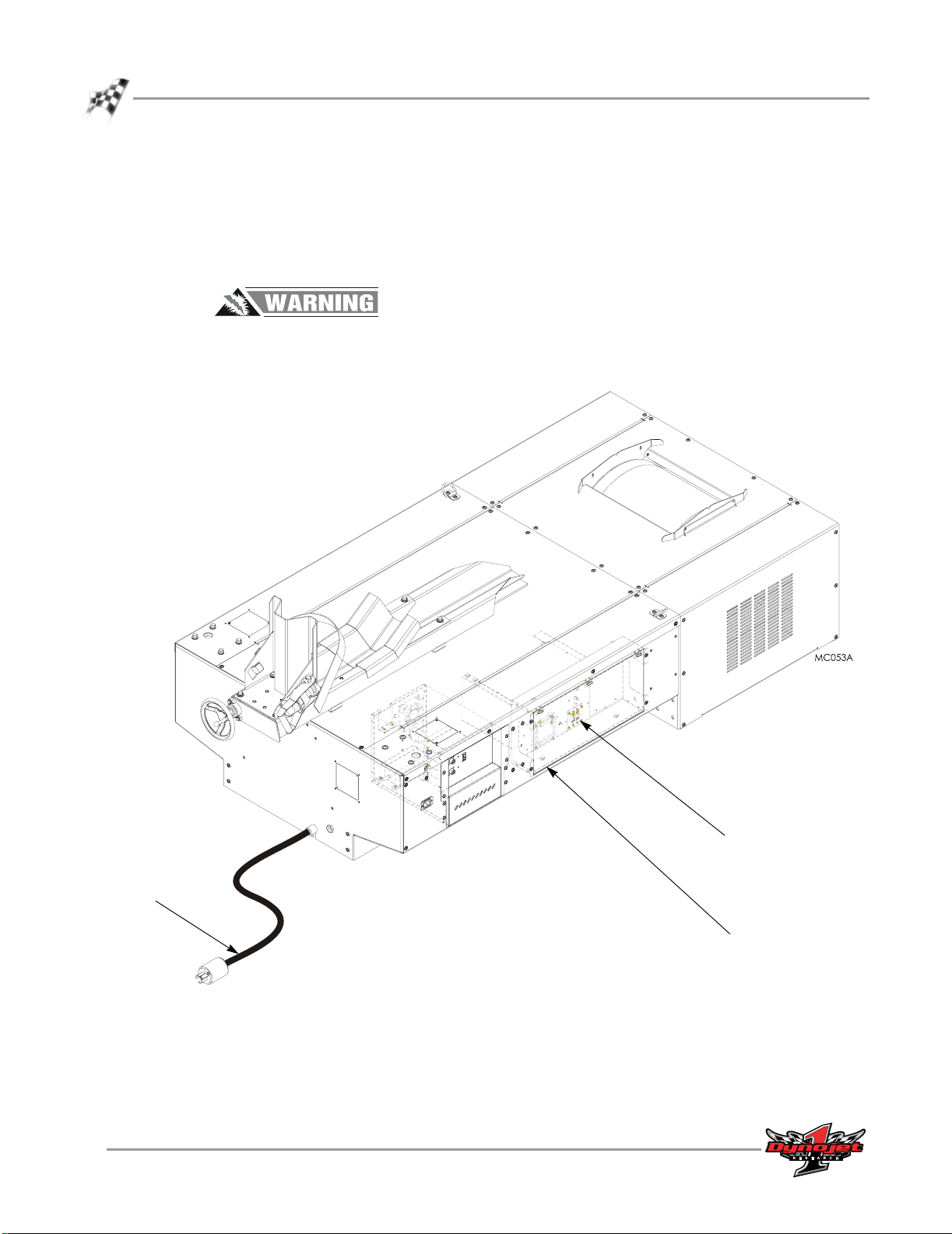
The high pressure blower supplies air to cool the bike’s engine. This section will walk
you through the blower installation procedures on the model 200i and 250i
motorcycle dynos.
To prevent possible injury, place the breaker inside the power distribution
enclosure to the off position and unplug the dyno. Refer to Figure 1 for breaker
location.
power cord
2
High Pressure Blower Installation Guide
breaker
power distribution enclosure
Figure 1: Model 200i/250i Breaker Location
Page 7

CONVENTIONS USED IN THIS MANUAL
The conventions used in this manual are designed to protect both the user and the
equipment.
example of convention description
The Caution icon indicates a potential hazard to the
dynamometer equipment. Follow all procedures
exactly as they are described and use care when
performing all procedures.
The Warning icon indicates potential harm to the
person performing a procedure and/or the
dynamometer equipment.
TECHNICAL SUPPORT
For assistance, please contact Dynojet Technical Support at 1-800-992-3525, or write
to Dynojet at 2191 Mendenhall Drive, North Las Vegas, NV 89031.
Visit us on the World Wide Web at www.dynojet.com where Dynojet provides state of
the art technical support, on-line shopping, 3D visualizations, and press releases
about our latest product line.
INSTALLATION GUIDE
Introduction
PARTS LIST
The following table lists all of the parts included in the High Pressure Blower
Installation kit (P/N 76722003). Check your kit against the parts listed to make sure
you have received all of the parts. If any part is missing, contact Dynojet Technical
Support.
part number description quantity
61328101 High Pressure Blower 2
63413004 Lower Blower Arm Assembly (longer arm and pin) 2
63413001 Upper Blower Arm Assembly 2
26215521 Washer, 1.87 x 1.25 ID x .25 Thick (Poly Washer) 2
35712992 Clamp Lever, 3/8-16 x 1.5” 2
Version 3 High Pressure Blower Installation Guide
3
Page 8

HIGH PRESSURE BLOWER
Installation
INSTALLATION
. . . . . . . . . . . . . . . . . . . . . . . . . . . . . . . . . . .
If you have a monitor tray, the support arm must be installed before the blower arm
assemblies. Refer to the Model 200i/250i Motorcycle Dynamometer Installation Guide
for more information.
INSTALLING THE BLOWER ARM ASSEMBLIES
Repeat the following steps for each blower arm assembly.
1 Place a 1/4-inch thick poly washer around the pin on the blower arm assembly.
2 Insert the pin on the blower arm assembly into the dyno.
3 Secure the clamp lever to the dyno.
blower arm
assembly
clamp lever
lower arm has longer
arm and pin
1/4-inch thick
poly washer
blower arm
assembly
clamp lever
4
High Pressure Blower Installation Guide
Figure 2: Install the Blower Arm Assemblies
Page 9

INSTALLING THE HIGH PRESSURE BLOWER ASSEMBLIES
Repeat the following steps for each blower assembly.
Note: Make sure the motor on each blower is facing out (away from the dyno)
and that the intake is facing in.
1 Place a 1/8” thick poly washer around the pin on the blower assembly.
2 Insert the pin on the blower assembly into the blower arm.
blower assembly
intake facing in
1/8-inch thick
poly washer
INSTALLATION GUIDE
Installation
blower arm
motor facing out
Figure 3: Install the Blower Assemblies
Version 3 High Pressure Blower Installation Guide
5
Page 10

HIGH PRESSURE BLOWER
Installation
POWER HOOKUP
Each blower has its own power cord and will plug directly into the dyno chassis.
1 Plug the power cord from the blower into the power source located on the dyno
chassis.
2 Activate the blower using the switch on the blower motor. The blowers are
independent of one another; each blower can be turned on and off individually.
Risk of injury. Eye protection required. Be aware of debris from blowers. Be
sure the blowers are free and clear of any obstruction. The blowers can run at
any time once the cord is plugged into a power source.
power cord
from blower
Figure 4: Power Hookup
plug into
dyno chassis
power cord
from blower
6
High Pressure Blower Installation Guide
Page 11

INSTALLATION GUIDE
Stand Alone Blower Base
STAND ALONE BLOWER BASE
. . . . . . . . . . . . . . . . . . . . . . . . . . . . . . . . . . .
The stand alone blower base was designed for use with pit dynos and automotive
dynos allowing you to direct air flow where you need it. The stand alone base will also
accommodate the older style fans.
PARTS LIST
The following table lists all of the parts included in the Stand Alone High Pressure
Blower Base kit (P/N 71329002). Check your kit against the parts listed to make sure
you have received all of the parts. If any part is missing, contact Dynojet Technical
Support.
part number description quantity
61328101 High Pressure Blower Assembly 2
61329001 Stand Alone Handle Assembly 2
61329111 Stand Alone Extension Assembly 2
61329600 Stand Alone Base Assembly 2
35712991 Clamp Lever, 3/8-16 x 3/4” 2
26215520 Washer, 1.87 x 1.25 ID x .12 Thick 2
INSTALLING THE BLOWER AND BASE ASSEMBLIES
Repeat the following steps for each blower and base assembly.
1 Secure the handle to the blower, if not already installed.
1a Remove the two 5/16-inch bolts from the blower.
1b Secure the handle to the blower using the 5/16-inch bolts you just removed.
2 Insert the pin on the blower assembly into the stand alone base.
3Tighten the clamp lever.
blower assembly
base
handle
bolt
clamp lever
Figure 5: Secure Blower to Base
Version 3 High Pressure Blower Installation Guide
7
Page 12

HIGH PRESSURE BLOWER
Stand Alone Blower Base
INSTALLING THE EXTENSION
The extension provides an extra twelve inches of height allowing you to precisely
direct air flow where you need it. Repeat the following steps for each blower and base
assembly.
1 Insert the pin on the extension assembly into the stand alone base. Tighten the
clamp lever.
2 Place a poly washer around the pin on the blower assembly.
3 Insert the pin on the blower assembly into the extension. Tighten the clamp lever.
blower assembly
washer
clamp lever
base
POWER HOOKUP
Each blower has its own power cord and will plug directly into a power source
located in your dyno room. Each blower must be plugged into a separate circuit.
• 17A at 120VAC each 50/60Hz
1 Plug the power cord from the blower into a power source located in your dyno
room.
Note: Each blower must be plugged into a separate circuit. When using the
blowers in conjunction with an eddy current brake (retarder), make sure the
retarder is plugged into a separate circuit than either of the blowers.
2 Activate the blower using the switch on the blower motor. The blowers are
independent of one another; each blower can be turned on and off individually.
extension
clamp lever
Figure 6: Installing the Extension
Risk of injury. Eye protection required. Be aware of debris from blowers. Be
sure the blowers are free and clear of any obstruction. The blowers can run at
any time once the cord is plugged into a power source.
8
High Pressure Blower Installation Guide
Page 13

M
ODEL
200/250 B
LOWER INSTALLATION
A PPENDIX
A
This appendix provides instructions for installing the high pressure blower assemblies
to the model 200/250 motorcycle dynamometer (dyno). To ensure safety and
accuracy in the procedures, perform the procedures as they are described.
This section will walk you through the blower installation procedures and adjusting
the extension arm assembly when a power carriage is installed.
PARTS LIST
. . . . . . . . . . . . . . . . . . . . . . . . . . . . . . . . . . .
The following table lists all of the parts included in the High Pressure Blower Retrofit
Installation kit (P/N 77020002). Check your kit against the parts listed to make sure
you have received all of the parts. If any part is missing, contact Dynojet Technical
Support.
part number description quantity
61328101 High Pressure Blower Assembly 2
63413002 Mounting Bracket and Extension Arm Assembly 1
26215520 Washer, 1.87 x 1.25 ID x .12 Thick (Poly Washer) 2
36582477 Bolt, 3/8"-16 x 1.5", Hex 4
36488100 Nut, 3/8"-16, Nylock 4
36932100 Washer, 3/8", Splitlock, Stl 4
High Pressure Blower Installation Guide
A-1
Page 14

APPENDIXA
Installation
INSTALLATION
. . . . . . . . . . . . . . . . . . . . . . . . . . . . . . . . . . .
The high pressure blower supplies air to cool the bike’s engine.
The blower extension arm assembly comes ready to mount to the tire carriage on the
dyno. However, if you have a power carriage installed on your dyno, you will need to
make adjustments to the extension arm assembly before mounting the assembly to
the dyno. Refer to “Modifying the Extension Arm Assembly (For Power Carriage
Only)” on page A-6.
To prevent possible injury, disconnect the battery before performing any dyno
maintenance or installing any optional accessory.
MODIFYING THE TIRE STOP
Older dynos may not have the four holes on the tire stop needed to mount the
extension arm assembly; you will need to modify the tire stop before continuing with
the blower installation instructions. Refer to Figure A-1 for hole size and placement.
A-2
High Pressure Blower Installation Guide
Figure A-1: Modify the Tire Stop
Page 15

INSTALLING THE EXTENSION ARM ASSEMBLY
The blower extension arm assembly comes ready to mount to the tire stop on the
dyno.
Note: If you have a power carriage installed on your dyno, you will need to make
adjustments to the extension arm assembly before mounting the assembly to the
dyno. Refer to “Modifying the Extension Arm Assembly (For Power Carriage
Only)” on page A-6.
1 Remove the two screws securing the extension arm assembly to the crate and
remove the assembly.
remove screws
MODEL 200/250 BLOWER INSTALLATION
Installation
clip zip tie securing poly washer
before installing blower
Figure A-2: Remove the Extension Arm Assembly from the Crate
2 Secure the main bracket on the extension arm assembly to the tire stop using four
3/8-16 x 1.5-inch bolts and four 3/8-inch washers.
Note: If you modified the tire stop, you will also need to use four 3/8-inch nylock
nuts.
bolt
washer
main bracket
tire stop
Figure A-3: Secure the Extension Arm Assembly to the Tire Stop
Version 3 High Pressure Blower Installation Guide
A-3
Page 16

APPENDIXA
Installation
INSTALLING THE HIGH PRESSURE BLOWER ASSEMBLIES
Repeat the following steps for each blower assembly.
Note: Your blowers may be different than the blowers shown in the following
figures. Installation procedures are the same.
1 Place a poly washer between the pin and the extension arm.
Note: The poly washer is secured to the extension arm with a zip tie. Clip the zip
tie before installing the blower assembly. Refer to Figure A-2.
2 Insert the pin on the blower assembly into the extension arm.
3 If not already installed, secure the hand knobs to the extension arm and to the
blower base.
Note: Your hand knobs may be different than the hand knobs shown in the
following figures.
blower assembly
poly washer
extension arm
hand knob
Figure A-4: Install the Blower Assemblies
A-4
High Pressure Blower Installation Guide
Page 17

POWER HOOKUP
Each blower has its own power cord and will plug directly into a power source
located in your dyno room. Each blower must be plugged into a separate circuit.
• 17A at 120VAC each 50/60Hz
1 Plug the power cord from the blower into a power source located in your dyno
room.
Note: Each blower must be plugged into a separate circuit. When using the
blowers in conjunction with an eddy current brake (retarder), make sure the
retarder is plugged into a separate circuit than either of the blowers.
2 Activate the blower using the switch on the blower motor. The blowers are
independent of one another; each blower can be turned on and off individually.
Risk of injury. Eye protection required. Be aware of debris from blowers. Be
sure the blowers are free and clear of any obstruction. The blowers can run at
any time once the cord is plugged into a power source.
MODEL 200/250 BLOWER INSTALLATION
Installation
Version 3 High Pressure Blower Installation Guide
A-5
Page 18

APPENDIXA
Installation
MODIFYING THE EXTENSION ARM ASSEMBLY (FOR POWER CARRIAGE ONLY)
When the blower assemblies are used with a power carriage, the following
modifications must be made to the extension arm assembly before mounting the
extension arm assembly to the dyno.
Note: These modifications should be made only when a power carriage is
installed.
1 Remove the four hand knobs from the extension arms.
2 Remove arm A, including the poly washer, and set aside.
3 Remove the bolt, lock washer, fl at washer, and spacer securing arm B to the main
bracket, including the poly washer, and set aside.
Note: Arm B is the only arm with a threaded pin.
hand knob
arm A
bolt
lock washer
flat washer
spacer
poly washer
hand knob
arm A
poly washer
arm B
Figure A-5: Modify the Extension Arm Assembly—Removing the Arms
threaded pin
arm B
hand knob
hand knob
A-6
High Pressure Blower Installation Guide
Page 19

hand knob
MODEL 200/250 BLOWER INSTALLATION
Installation
4 Flip arm A over, place the poly washer on the pin, and insert into the main
bracket from the top.
5 Flip arm B over, place the poly washer on the pin, and insert into arm A from the
bottom. Secure Arm B using the bolts, washers, and spacers removed earlier.
Note: Arm B is the only arm with a threaded pin.
6 Replace the four hand knobs removed earlier.
7 Continue with “Installing the Extension Arm Assembly” on page A-3, “Insta lling
the High Pressure Blower Assemblies” on page A-4, and “Power Hookup” on page
A-5 to complete the blower installation.
hand knob
arm A
threaded pin
hand knob
arm B
main bracket
arm A
hand knob
Figure A-6: Modify the Extension Arm Assembly—New Arm Configuration
arm B
Version 3 High Pressure Blower Installation Guide
A-7
Page 20

 Loading...