

Page 1

CLUTCH KIT
INSTALLATION GUIDE
2016-2018 Polaris General 1000
PARTS LIST
3 CLUTCH ARMS
1 PRIMARY SPRING SILVER
1 SECONDARY SPRING PURPLE
1 HELIX
PLEASE READ ALL DIRECTIONS BEFORE STARTING INSTALLATION
2191 MENDENHALL DRIVE, NORTH LAS VEGAS, NV 89081
800-992-4993 WWW.DYNOJET.COM
19-DCK3
6 MAGNETS (3/16”)
27 MAGNETS (3/8”)
1 WASHER
Page 2
CLUTCH KIT ADJUSTMENT
SETTINGS
INTENDED USE ELEVATION MAGNET POSITION TOTAL WEIGHT PRIMARY SPRING SECONDARY SPRING
Trail Std Tire
Trail 30” Tire
Paddle Tire / Heavy load
RECOMMENDED SETTINGS FOR HIGH ELEVATION
Subtract 1 Magnet (from each arm starting from toe side)
Subtract 2 Magnets (from each arm starting from toe side)
Subtract 3 Magnets (from each arm starting from toe side)
Subtract 4 Magnets (from each arm starting from toe side)
0-2500 ft 1-3-3-2-0 68 gr SILVER PURPLE
0-2500 ft 1-3-3-1-0 66 gr SILVER PURPLE
0-2500 ft 1-3-3-0-0 65 gr SILVER PURPLE
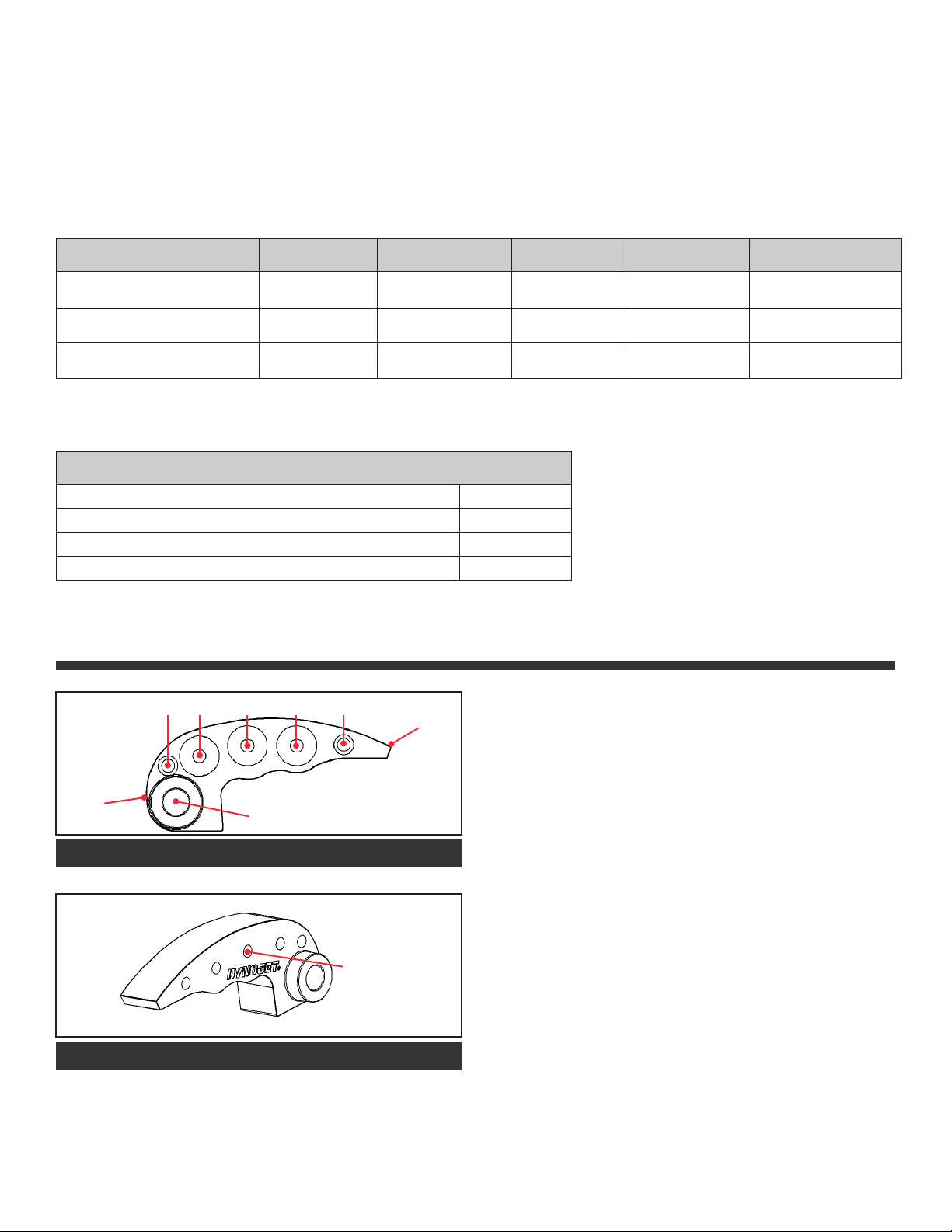
CLUTCH ARM ADJUSTMENT
MAGNET POS 1 2 3 4 5
TOE
3000 ft
6000 ft
7500 ft
9000 ft
LOAD MAGNETS PER THE TABLE ABOVE. MAKE SURE EACH
CLUTCH ARM IS LOADED WITH THE SAME AMOUNT OF
WEIGHT.
MORE WEIGHT NEAR HEEL INCREASES ACCEL
•
MORE WEIGHT AT TOE DECRESASES RPM
HEEL
PIVOT
LOAD MAGNETS STARTING AT HEEL - POS #1
USE A SMALL
ALLEN KEY OR
SIMILAR TO PUSH
THE MAGNETS
OUT FROM THIS
SIDE
TO REMOVE MAGNETS
19-DCK3 CLUTCH KIT 16-18 POLARIS GENERAL 1000
•
1 MAGNET CHANGE WILL ALTER RPM
•
APPROXIMATELY 150RPM
OUR SETTINGS ARE A GENERAL BASELINE. MANY THINGS
CAN EFFECT CLUTCH SETUP:
TIRE BRAND & SIZE
•
STATE OF CLUTCH WEAR
•
DRIVEBELT CONDITION
•
ENGINE POWER OUTPUT
•
ENVIRONMENT CONDITIONS
•
Page 3

INSTALLATION INSTRUCTIONS
IT IS RECOMMENED TO HAVE AN AUTHORIZED POLARIS
TECHNICIAN INSTALL THE CLUTCH KIT AS SPECIAL TOOLS
ARE NEEDED TO COMPLETE THE INSTALLATION.
Removing the left hand side rear shock gives better access
to the clutch housing and parts but is not necessary for
installation. Remove all the 8mm head bolts for the plastic,
clutch housing. Remove clutch housing. Mark the direction
of the drivebelt. Remove the drivebelt. Using the Polaris
clutch puller part #2872085 remove the primary clutch. It
is recommended to grease the threads of the clutch puller
before usage. Remove the 6 bolts for the primary spring
cover. Remove the bolts evenly as there is a significant
amount of spring pressure.
Install the supplied plastic washer to the inside of the stock
spider plate.
Replace the stock spring with the Dynojet spring. When reassembling make sure to align the tab on the Dynojet spring
with the notch in the sheave. Also align the “X” marks on
the spider plate and sheave. Install the Dynojet helix. The
orientaion of the helix is not important. Apply blue loctite
and torque the retaining bolts to 48 in-lb (5 Nm).
Reinstall the primary clutch on the output shaft. Torque the
retaining bolt to 96 ft-lb (130 Nm). Reinstall the secondary
clutch onto the output shaft. Torque the retaining bolt to
38 ft-lb (52 Nm) Reinstall the drivebelt.
Remove the clutch arms using 3/8” socket and 1/8” allen key. Install the Dynojet clutch arms with the proper
amount of weight. Refer to chart on page 2. Replace the
stock spring with the Dynojet SILVER spring and reinstall
the spring cover. Tighten the 6mm bolts evenly to 9 ft-lb (12
Nm).
Remove the secondary
clutch. Use a 15mm socket
to remove the retaining bolt
and slide the secondary
clutch off the input shaft.
Remove the 4 torx head
bolts. The helix is under extreme spring pressure. Use
a clutch compression tool.
TUNING NOTES
For best performance your RPM when checked at 50mph
should be 8400rpm. This should be checked on a surface
that offers good traction and tested with normal load in the
vehicle. Adjustments to overall weight of each clutch arm
may be necessary to achieve this RPM target.
If you were to test on the street and then ride in the sand
or mud it is not uncommon to see a loss of 300-400rpm if
using paddle tires.
Our settings are based on using a PVCX tune in the ECM for
optimal performance.
TOOLS NEEDED FOR INSTALLATION
PULLER (2872085)
•
21MM SOCKET
•
15MM SOCKET
•
T27 TORX
•
3/8” SOCKET
•
1/8” ALLEN KEY
•
INSTALLATION GUIDE
Page 4

PUSH THE LIMIT.
WWW.DYNOJET.COM
© 2018 DYNOJET RESEARCH ALL RIGHTS RESERVED
 Loading...