

Page 1

P/N: 975389 | Rev: current | ECO: xxxxx
From lab to production,
-1-
ViscoIndicator
providing a window into the process
Rheological sensing for the masses
Assembly, Installation
& Service Manual
www.dynisco.com
Page 2

P/N: 975389 | Rev: current | ECO: xxxxx
From lab to production,
-2-
providing a window into the process
www.dynisco.com
Page 3

P/N: 975389 | Rev: current | ECO: xxxxx
From lab to production,
-3-
providing a window into the process
Contents
1 General ............................................................................................................................................................. 5
1.1 Important information about the use of this manual ............................................................ 5
2 Safety ................................................................................................................................................................ 6
2.1 Safety summary .................................................................................................................................... 6
2.2 Obligation of the operator to exercise due care ...................................................................... 7
2.3 Obligation of the personnel to exercise due care .................................................................... 8
3 Transportation, handling, storage ..................................................................................................... 10
3.1 System Description .......................................................................................................................... 10
3.2 Transportation .................................................................................................................................. 10
3.3 Inspection upon receipt ................................................................................................................. 10
3.4 Storage conditions............................................................................................................................ 10
3.5 What's in the boxes .......................................................................................................................... 11
4 Assembly ...................................................................................................................................................... 14
4.1 Assemble IRCU-STAND (optional) ............................................................................................. 14
4.2 Mount RCU to the stand ................................................................................................................. 21
4.3 Attach the RSU (Head) to the stand ........................................................................................... 23
4.4 Attach the HMI to the stand .......................................................................................................... 29
4.5 Install Vortex coolers into RSU & RCU (option).................................................................... 30
4.6 Attach Vortex cooler regulators and tubing (option) ......................................................... 31
4.7 Attach ViscoIndicator Cable Bundle: electrical cables between RSU, HMI to RCU . 31
4.8 Attach RCU power cable to RCU .................................................................................................. 31
5 Installation .................................................................................................................................................. 33
5.1 Process Connection Tie-in ............................................................................................................. 33
5.2 Connect VI system assy to Process Connection .................................................................... 35
5.3 Install PIV heater and RTD ............................................................................................................ 37
5.4 Connect cables between process connection and RSU ...................................................... 39
5.5 Connect airlines to Vortex regulators (option) ..................................................................... 39
5.6 Insulate supply tube, ext. tube assy ends, dump valve and PIV ...................................... 39
5.7 Connect RCU cable to main line power .................................................................................... 39
www.dynisco.com
Page 4

P/N: 975389 | Rev: current | ECO: xxxxx
From lab to production,
-4-
providing a window into the process
6 Mechanical/pneumatic parts - Operation ....................................................................................... 40
6.1 Vortex cooler ...................................................................................................................................... 40
6.2 IRCU-STAND casters ........................................................................................................................ 40
6.3 Dump valve ......................................................................................................................................... 41
6.4 Process Isolation Valve (PIV) ....................................................................................................... 43
6.5 Rheological Sensing Unit (RSU) Extrudate Stream ............................................................. 43
7 HMI Operation (Obtaining rheological measurements from the ViscoIndicator) .......... 44
8 Preventative Maintenance .................................................................................................................... 45
8.1 Check RSU enclosure for plastic leaks ...................................................................................... 45
9 Service ........................................................................................................................................................... 46
9.1 Changing RSU burst plug ............................................................................................................... 46
9.2 Changing Pressure Transmitter .................................................................................................. 46
9.3 Changing capillary ............................................................................................................................ 46
9.4 Detaching VI main system from process connection .......................................................... 47
9.5 Preparing VI system for shipment ............................................................................................. 47
10 Support/Contact Dynisco ...................................................................................................................... 48
10.1 Recommended replacement parts / list and drawings of replacement parts ...... 48
11 Customer service ...................................................................................................................................... 49
12 Warranty ...................................................................................................................................................... 50
www.dynisco.com
Page 5

P/N: 975389 | Rev: current | ECO: xxxxx
From lab to production,
-5-
providing a window into the process
1 General
1.1 Important information about the use of this manual
This manual covers the Assembly, Installation and Service of the ViscoIndicator. The
operation of the ViscoIndicator is covered in a separate manual (Dynisco p/n 974175).
www.dynisco.com
Page 6

P/N: 975389 | Rev: current | ECO: xxxxx
From lab to production,
-6-
providing a window into the process
2 Safety
All safety instructions must be heeded and observed. Non-observance of safety instructions
may cause damage to life and health of persons, environmental damage and/or extensive
damage to property.
Observing the safety instructions included in the operating instructions will help to avoid
dangers, to operate the installation profitably and to secure the full use of the product.
2.1 Safety summary
The following are recommended safety precautions unrelated to any specific procedures in
this manual and therefore do not appear elsewhere. Personnel must understand and apply
them as appropriate during all phases of operation and maintenance. IN ALL CASES, BE
PRUDENT.
Keep away from live circuits
Do not replace components or make adjustments inside equipment with power turned on.
To avoid injuries, always remove power and discharge and ground a circuit before touching
it. When making electrical connections, the services of a qualified electrician must be
employed. Contact with live electrical circuits can cause serious personal injury or death.
Be sure no circuits are energized during installation, connection or removal of any
electrical cables or lines.
Examine the cabling and housings regularly for damage. Machines with damaged wiring or
control systems must be disconnected from the power line immediately and must not be
operated again until they have been repaired by qualified personnel.
Wear protective clothing
Wear protective clothing (gloves, apron, goggles, etc.) approved for the materials and tools
being used.
Provide adequate ventilation
Provide ventilation to remove heat and noxious odors and to prevent the accumulation of
asphyxiates such as nitrogen gas.
Avoid hot surfaces
Keep hands away from hot surfaces and materials. Contact with hot surfaces or materials
can cause blistering and third degree burns. Wear approved, clean, thermally insulated
gloves when handling these components. Should injury occur; immerse injured area in cold
water and get immediate medical attention.
www.dynisco.com
Page 7

P/N: 975389 | Rev: current | ECO: xxxxx
From lab to production,
-7-
providing a window into the process
Avoid tipping the stand
After assembling the stand, install the RCU on the stand before installing the RSU.
Installing the RSU to the stand before installing the RCU can make the stand unstable. Take
care to follow this assembly order unless the stand has been properly secured.
The optional stand has flexible configuration capability. It is possible to configure it is such
a way that it is unstable. Take care not to use it this way unless it is properly secured.
Take care to avoid tipping the stand due to an impact (from something/somebody running
into the stand), or from a collision (a forklift or crane load, etc being driven into it), or while
moving the stand. Do not climb on or support yourself with this stand. Use signs or
barriers as appropriate.
When moving the stand around on its castors, there is danger that it could suddenly stop
sharply when it rolls over uneven floor surfaces or other obstructions (screws, granules),
and could tip. Appropriate caution must therefore be taken - roll the unit slowly!
The castors on the base of the stand must be examined regularly for damage and secure fit,
damaged castors are to be replaced immediately.
2.2 Obligation of the operator to exercise due care
The Dynisco component conforms to the state of the art technology and ensures a
maximum of safety. In practical operation, this safety can, however, be achieved only if all
necessary measures are taken. The obligation of the plant operator to exercise due care
includes planning these measures and supervising their execution.
Especially, the operator has to ensure that:
• The Dynisco component will be used only in accordance with the intended purpose.
• The Dynisco component will be operated in a flawless, functionally efficient
condition and that, in particular, the functional efficiency of the safety devices will
be checked at regular intervals.
• The necessary personal protective equipment for the operating, maintenance, and
service personnel will be available and used by them.
• The operating instructions are always available completely and fully legibly at the
installation location of the Dynisco component. It must be guaranteed that all
persons who have to work with the Dynisco component can consult the operating
instructions at any time.
www.dynisco.com
Page 8

P/N: 975389 | Rev: current | ECO: xxxxx
From lab to production,
-8-
providing a window into the process
• Only sufficiently qualified and authorized personnel will operate, maintain, and
repair the Dynisco component.
• Instructions concerning all relevant questions of industrial safety and
environmental protection will regularly be given to the personnel, and that these
persons will know and understand the operating instructions and, particularly, the
safety instructions contained.
• All safety and warning instructions, attached to the Dynisco component, will not be
removed and will remain fully legible.
• The service instructions in accordance with the industrial safety legislation and the
ordinance for the use of work materials will have to be made available as a
supplement to the operating instructions.
2.3 Obligation of the personnel to exercise due care
The ViscoIndicator melt rheometer may only be operated by persons trained, instructed
and authorized to do so. These persons must know the operating instructions and act
accordingly. The respective competences of the staff must be clearly determined.
The following work described in these instructions may be carried out by qualified persons
only:
• Assembly
• Installation
• Operation
• Servicing
Especially, the staff has to ensure that:
• Inexperienced operating personnel should only work with the Dynisco component
while directly monitored by an experienced person.
• All persons operating and maintaining the Dynisco component must read the
operating instructions and confirm by their signature that they understood the
operating instructions.
• Unauthorized persons do not stay in the working area of the Dynisco component.
www.dynisco.com
Page 9

P/N: 975389 | Rev: current | ECO: xxxxx
From lab to production,
-9-
providing a window into the process
• The working area will be left only if all movable parts have come to a stop after
having switched off the Dynisco component.
• In addition to the operating instructions, the service instructions within the
meaning of the industrial safety legislation and the ordinance for the use of work
materials will be observed.
• In case of malfunctions, the operator or the supervisors will be informed.
• The necessary personal protective equipment for the operating, maintenance, and
service personnel will be used.
www.dynisco.com
Page 10

P/N: 975389 | Rev: current | ECO: xxxxx
From lab to production,
-10-
providing a window into the process
3 Transportation, handling, storage
3.1 System Description
3.2 Transportation
The machine is usually placed on a palette or inside a card board box for shipping. The
dimensions ensure that no damage can occur under normal shipping conditions. The
ViscoIndicator is wrapped in plastic sheeting for transportation – for overseas transport
the palette is covered in addition with a suitable wooden or a cardboard box.
Because of the low weight of the ViscoIndicator the machine can be removed manually
from the palette or the card board box.
When moving the ViscoIndicator mounted in the optional stand on castors, watch out for
unevenness and obstacles on the floor. Sudden stops can cause the machine to tip over!
3.3 Inspection upon receipt
Check the delivery for completeness and signs of shipping damage. Any shipping damages
must be sent to the shipping carrier and Dynisco in writing.
Immediately submit any claims in writing to the following address:
For Americas and APAC: For EMEA:
Dynisco Dynisco Europe GmbH
38 Forge Parkway Pfaffenstrasse 21
Franklin, MA 02038, USA 74078 Heilbronn, Germany
Fax: +1 508 541 6206 Fax: +49 (7131) 297 166
3.4 Storage conditions
When intermediate storage is required upon delivery, be sure to:
• choose a dry room with a moderate temperature (approx. 18° C)
• leave the ViscoIndicator in the plastic sheeting
• avoid storing the ViscoIndicator outside. If this is inevitable, be sure to:
- leave the ViscoIndicator in its original packaging
- provide an additional rain cover for the ViscoIndicator
- repair any defective paint work immediately
- position the ViscoIndicator on squared timber or a palette.
www.dynisco.com
Page 11
P/N: 975389 | Rev: current | ECO: xxxxx
From lab to production,
-11-
Sample
Tube
PIV
RSU
providing a window into the process
As a rule, damages caused by inadequate storage will void any claims under the warranty
3.5 What's in the boxes
The ViscoIndicator provides continuous measurements of the melt flow rate, apparent
viscosity, or intrinsic viscosity directly on the extruder.
The ViscoIndicator consists of the following:
A sample tube that transfers polymer from the process to the ViscoIndicator for
measurement.
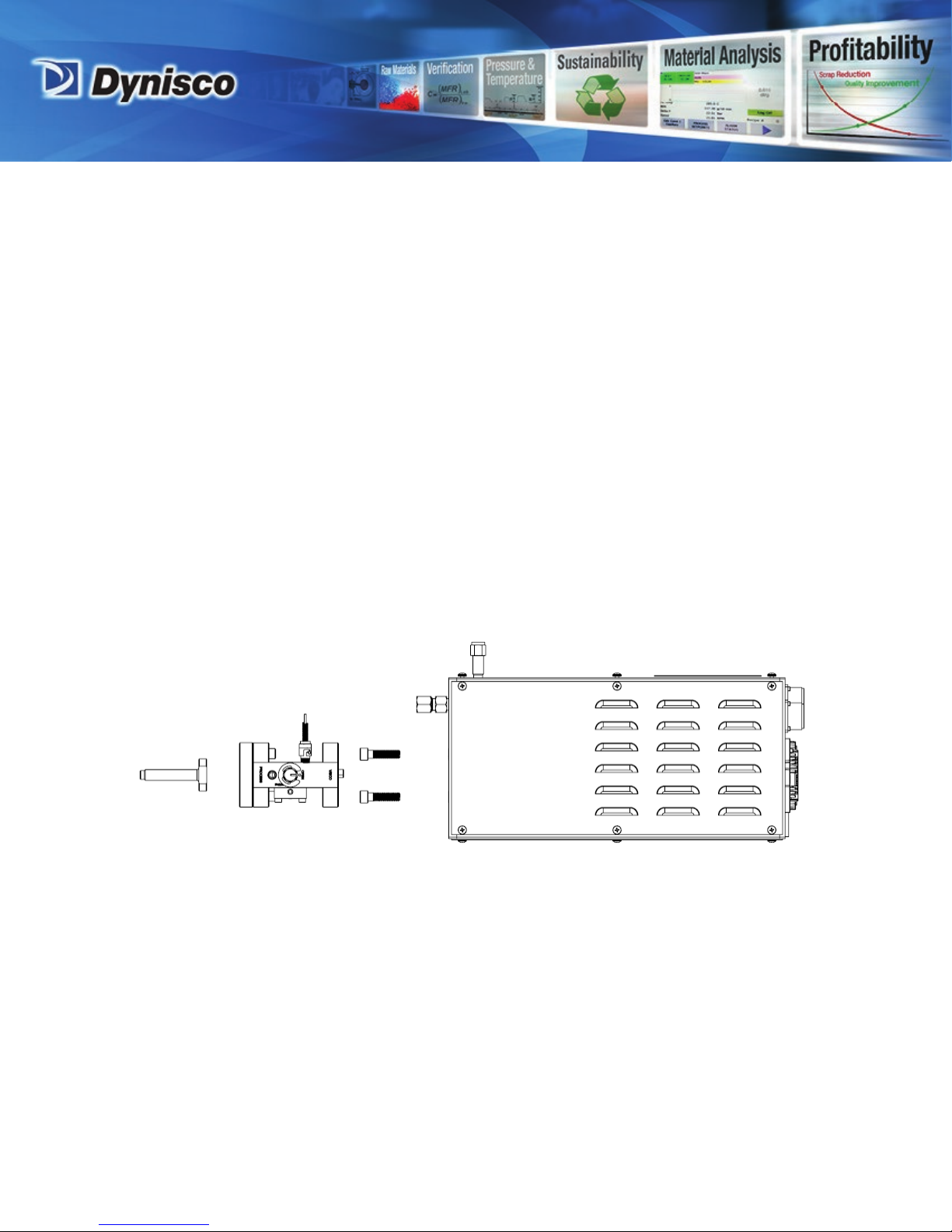
The Process Isolation Valve (PIV) allows the flow of polymer to the ViscoIndicator to be
shut off, allows purging, and allows a pressure transducer measurement on the process
line.
A Rheological Sensing Unit (RSU) that measures the properties of the resin. It can be
mounted on extruders, reactors, or molten polymer transfer lines in various orientations.
www.dynisco.com
Page 12
P/N: 975389 | Rev: current | ECO: xxxxx
From lab to production,
-12-
providing a window into the process
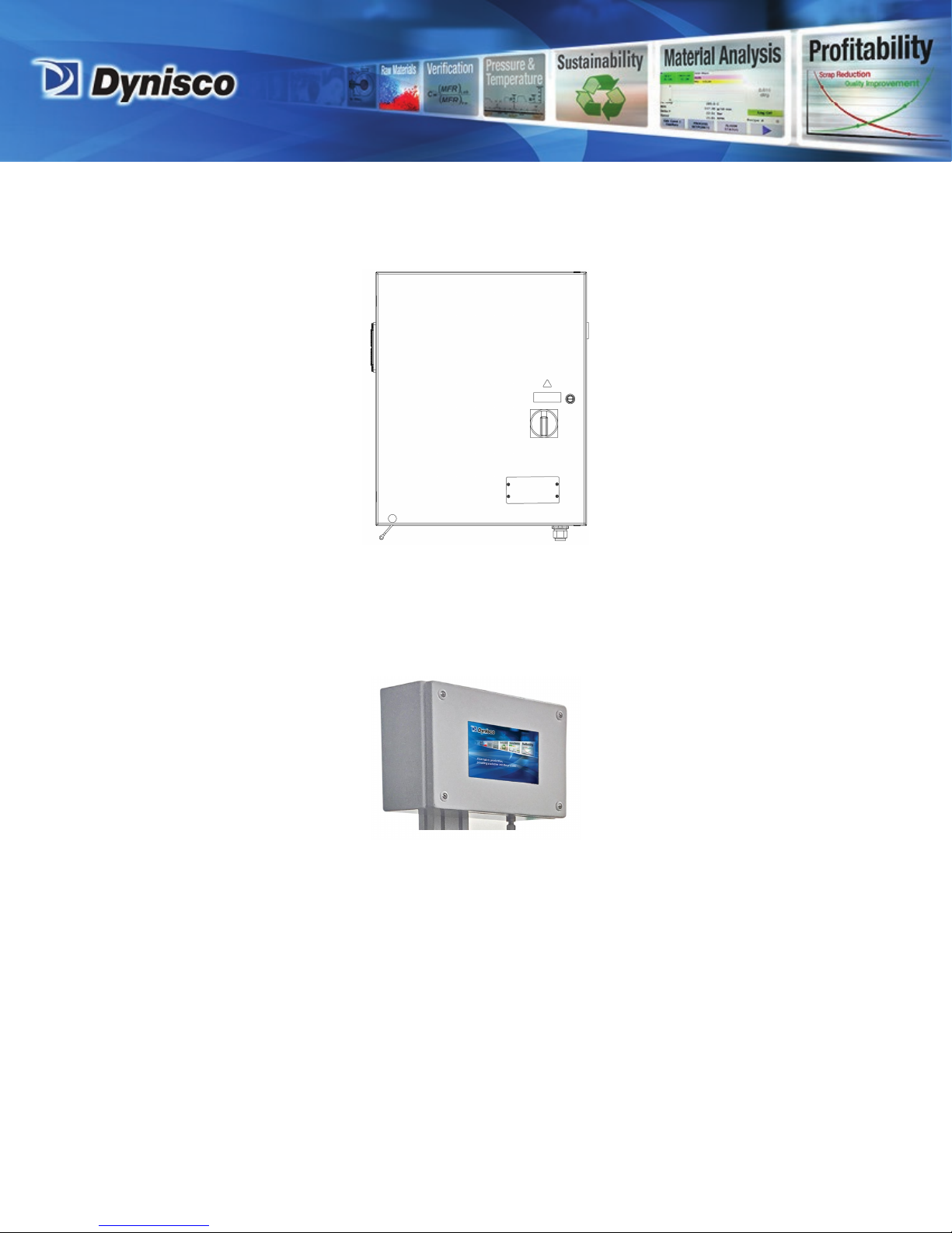
A Rheological Control Unit (RCU) that controls the measurement parameters of the RSU
(temperature, pressure, flow rate), and communicates to an HMI.
RCU
The Human Machine Interface (HMI) remotely manages test parameters and provides
measured and computed material properties. It provides rheological data similar to a
Laboratory Capillary Rheometer or MFI readings similar to a Melt Flow Indexer.
HMI
Because of the system options available, please refer to the purchase order for the
particular configuration and accessories. However, the following items are part of the
standard ViscoIndicator:
ViscoIndicator Cable Bundle: These are the cables that connect the RCU to the RSU and
HMI.
Additional Items:
Orifices
Orifice removal tool
www.dynisco.com
Page 13
P/N: 975389 | Rev: current | ECO: xxxxx
From lab to production,
-13-
providing a window into the process
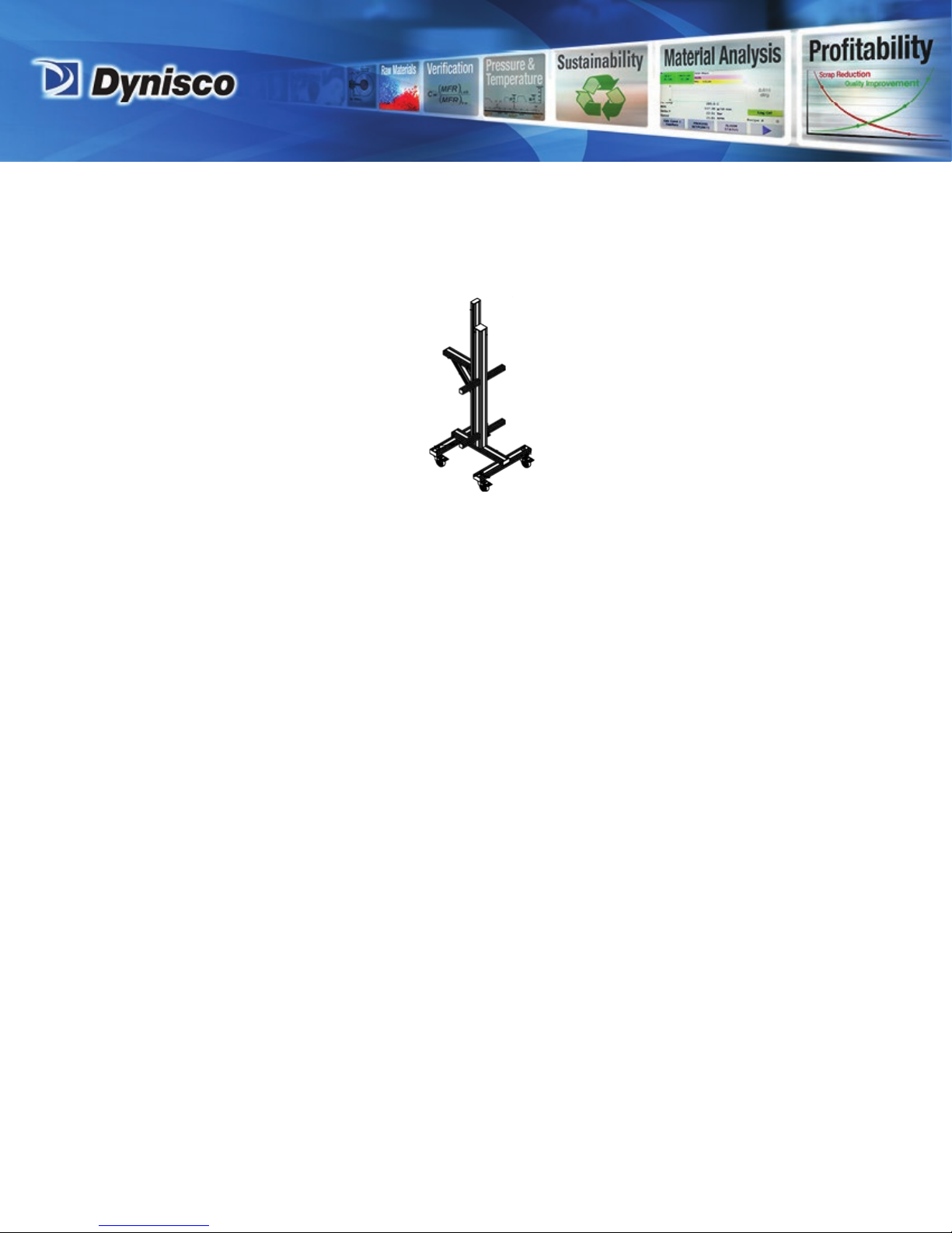
Optional Items:
Vortex cooler
Stand
www.dynisco.com
Page 14
P/N: 975389 | Rev: current | ECO: xxxxx
From lab to production,
-14-
providing a window into the process
4 Assembly
4.1 Assemble IRCU-STAND (optional)
If the optional IRCU-STAND has been purchased, the locations for mounting the RSU, RCU,
and HMI have been predetermined. Assemble the stand per the instructions below. If this
stand was not purchased, skip to section 3.2.
NOTE: Item numbers refer the numbers on drawing IRCU-STAND (included at the end of
this section), unless noted.
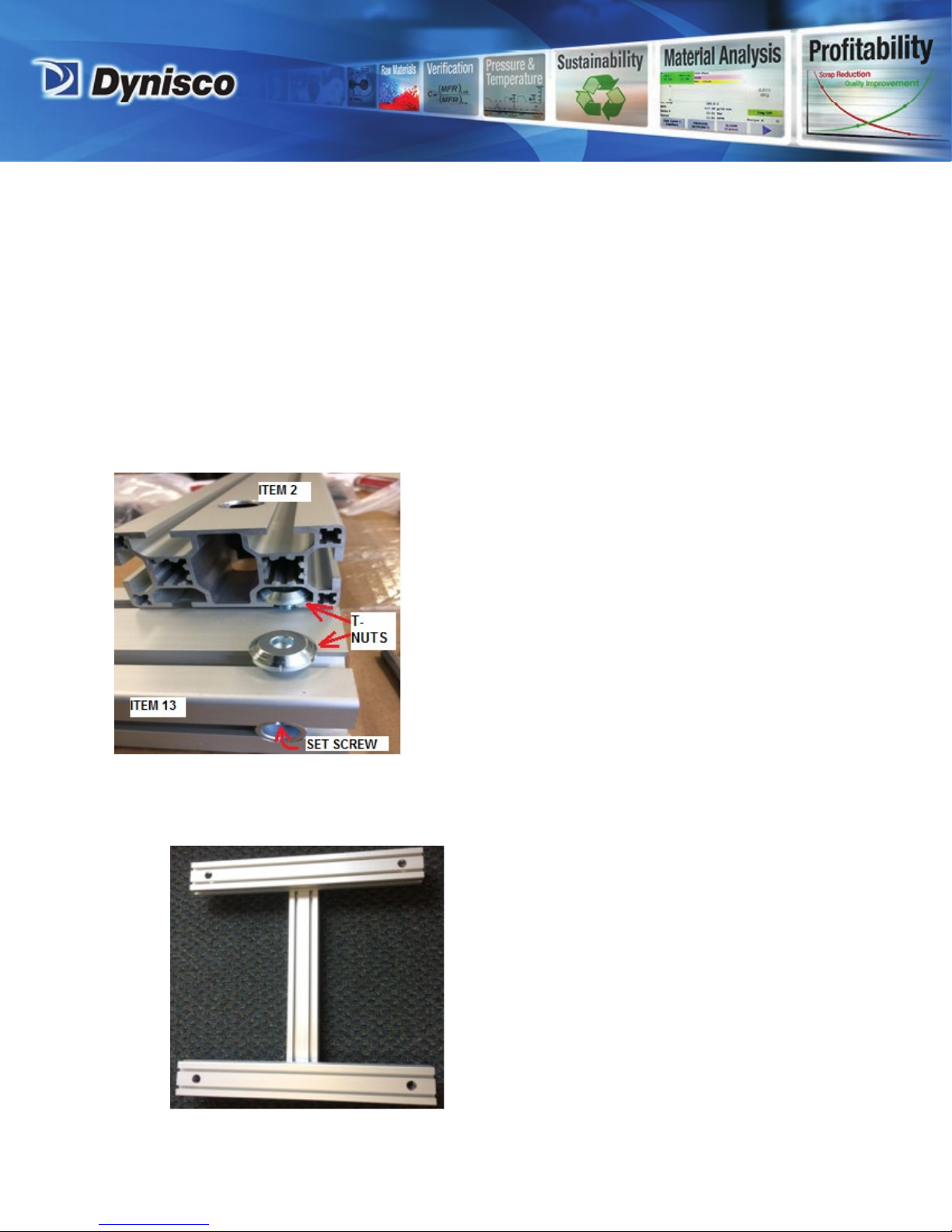
4.1.1 Assemble Base
• Loosen the four connector set screws on the cross brace extrusion (item 13 - QTY 1)
• On each end of item 13, slide one caster extrusion (item 2 - QTY 2) onto the T nuts
• The two T nuts on each end of item 13 slide into one slot of item 2.
• Center and position each item 2 perpendicular to item 13
•
www.dynisco.com
Page 15
P/N: 975389 | Rev: current | ECO: xxxxx
From lab to production,
-15-
providing a window into the process
• Tighten all four connector set screws on item 13
4.1.2 Assemble Mast
• Loosen the two connector set screws on the rectangular mast (item 3 - QTY 1)
• Loosen the two connector set screws on the square mast (item 1 - QTY 1)
• Slide the two masts together using the T nuts on each mast
• Tighten all four connector set screws on the masts
• Insert two M5 T-nuts (item 17) into upper end of item 3
• Attach endcap to lower end of item 3
www.dynisco.com
Page 16

P/N: 975389 | Rev: current | ECO: xxxxx
From lab to production,
-16-
providing a window into the process
4.1.3 Assemble Base to Mast
• Loosen the four connector set screws on the lower end of item 1
• Slide the four T-nuts on the lower end of item 1 into two slots of item 13, orienting
the mast assy as shown
• Position item 1 approximately in the center of item 13
• Tighten the four connector set screws on the lower end of item 1
CAUTION: The positioning of the mast to the base described above may not provide
the most stable configuration when an RSU is later mounted to the stand.
Repositioning the mast relative to the base may provide additional stability
(installation specific).
www.dynisco.com
Page 17

P/N: 975389 | Rev: current | ECO: xxxxx
From lab to production,
-17-
providing a window into the process
4.1.4 Assemble and attach RSU support to mast
• Loosen the four connector set screws at each end of item 12 (QTY 1)
• Slide two t-nuts on one end of item 12 into end of item 11 (QTY 1) without
connectors
• Tighten two connector set screws of item 12
• Slide the RSU support onto item 3
• Tighten the two connector set screws of item 11 for the desired height of the
ViscoIndicator RSU
• Loosen the connection between items 11 and 12, and move item 12 to make both
ends of item 12 flush to items 11 and 3
• Tighten all four connector set screws of item 12
•
CAUTION: The higher the RSU support on the mast the greater the instability.
Position the RSU support as low as possible (installation specific).
www.dynisco.com
Page 18

P/N: 975389 | Rev: current | ECO: xxxxx
From lab to production,
-18-
providing a window into the process
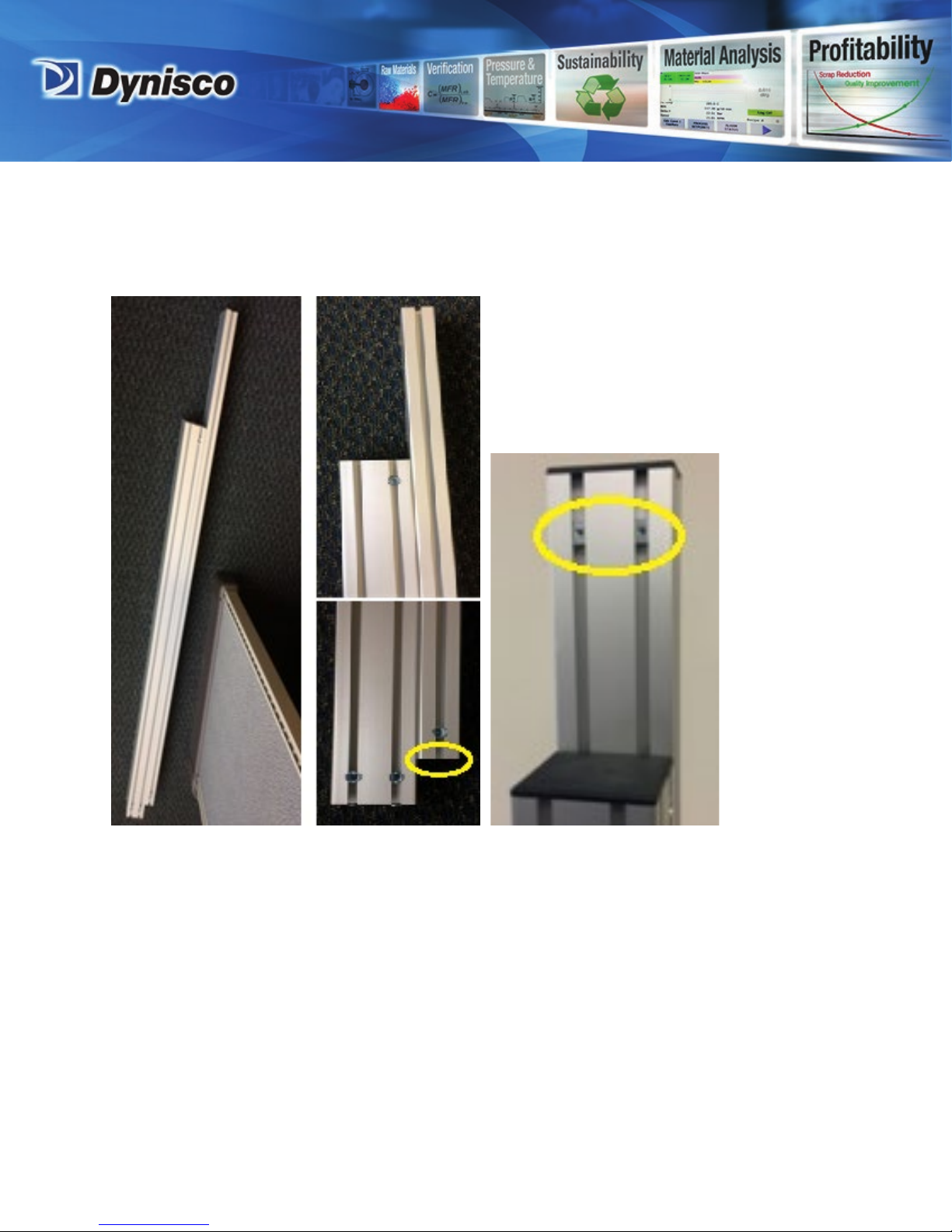
4.1.5 Install RCU cabinet support arms
• Loosen the connector set screws on the cabinet support arms (item 6 - QTY 4)
• Attach each item 6 onto item 1 as shown;
• use farthest slot from the RSU support
• position the connector set screws facing the RSU support (red circle)
• position the two lower arms 2in from item 13
• position the two upper arms approximately 17in from the lower arms (the top arms
will be moved to a final position later)
• Install one M5 T-nut (item 17) into each item 6 in the slot opposite the connector set
screw slot (yellow circles)
•
CAUTION: Raising the position of the cabinet support arms will increase stand
instability.
www.dynisco.com
Page 19

P/N: 975389 | Rev: current | ECO: xxxxx
From lab to production,
-19-
providing a window into the process
4.1.6 Install Casters
• Install four casters (item 7 - QTY 4) into two pcs of item 2
• Place a washer (item 9 - QTY 4) over each threaded caster shaft onto item 2
• Thread a nut (item 10 - QTY 4) onto each threaded caster shaft and tighten until
caster is secure
4.1.7 Install Endcaps
• Press cover endcaps into extrusion ends:
• item 5 - QTY 1 - install on top end of item 1
• item 8 - QTY 4 - install on exposed ends of item 6
• item 4 - QTY 9 - install on all remaining exposed ends
www.dynisco.com
Page 20

P/N: 975389 | Rev: current | ECO: xxxxx
From lab to production,
-20-
providing a window into the process
www.dynisco.com
Page 21

P/N: 975389 | Rev: current | ECO: xxxxx
From lab to production,
-21-
providing a window into the process
4.2 Mount RCU to the stand
WARNING: It is recommended to install the RCU on the stand before installing the
RSU. Installing the RSU to the stand before installing the RCU will tend to make the
stand more unstable.
NOTE: Item numbers refer to drawing IRCU-STAND (included at the end of the previous
section), unless noted.
NOTE: Dynisco P/N 1016335 consists of two parts; a lower and upper bracket.
•
4.2.1 Attach lower brackets to the stand
• Center and attach one lower bracket (part of Dynisco P/N 1016335) to the upper
cabinet support arms using two M5 x 12mm long button head cap screws (Dynisco
P/N 550186).
• Put the two screws through the holes nearest the ends of the bracket, and then
thread the screws into the M5 T-nuts (item 17) located in the slots of item 6
• Attach a second lower bracket to the lower cabinet support arms, as described
above.
www.dynisco.com
Page 22

P/N: 975389 | Rev: current | ECO: xxxxx
From lab to production,
-22-
providing a window into the process
4.2.2 Attach the bottom of the RCU to the lowest bracket on the stand
CAUTION: The RCU is heavy (20+ lbs). It is recommended that two physically capable
people lift the RCU carefully to install it on the stand in a controlled fashion.
• Center and attach the bottom of the RCU to the lowest bracket of the stand by
centering the RCU on the mast, then bringing the RCU down until the lower bracket
seats (red circle)
• The RCU is not fully attached! Hold the RCU up against the mast until the next step is
completed!
www.dynisco.com
Page 23

P/N: 975389 | Rev: current | ECO: xxxxx
From lab to production,
-23-
providing a window into the process
4.2.3 Attach the top of the RCU to the upper bracket on the stand
• While one person continues to hold the RCU against the mast, another person
loosens then slides the upper stand bracket upwards until it seats in the upper RCU
bracket. Tighten the two M5 screws to secure the upper stand bracket in place.
4.3 Attach the RSU (Head) to the stand
NOTE: Item numbers in this section refer to item numbers on drawing IRSU-MOUNT
(included at the end of this section), unless noted.
4.3.1 Remove the IRSU-MOUNT from the RSU
CAUTION: The following step requires two people.
CAUTION: The RSU/PIV/IRSU-MOUNT weighs approx.40 lbs. Only physically
capable personnel should lift this assembly.
• Remove the RSU/PIV/IRSU-MOUNT assembly from the shipping box, and carefully
rest it on a surface using the bottom of the IRSU-MOUNT while continuing to
support the assembly so it does not tip over.
• A second person should now detach the RSU/PIV assy from the IRSU-MOUNT by
removing the four screws (2 screws on a side) holding the RSU to the IRSU-MOUNT
(red circles)
www.dynisco.com
Page 24

P/N: 975389 | Rev: current | ECO: xxxxx
From lab to production,
-24-
providing a window into the process
• Place the RSU/PIV assy on a stable surface.
www.dynisco.com
Page 25

P/N: 975389 | Rev: current | ECO: xxxxx
From lab to production,
-25-
providing a window into the process
4.3.2 Attach the IRSU-MOUNT to the stand
• Install two M8 T-nuts (item 8 - QTY 2) into the upper slots of item 11 of drawing
IRCU-STAND (yellow circle)
• Position the IRSU-MOUNT on top of the inserted M8 T nuts, so the thru holes in item
6 are as close as possible to the mast (red circle)
• Slide two M8 bolts (item 7 - QTY 2) thru the two holes in item 6, and into the two M8
T-nuts and begin to tighten
• Slide the IRSU-MOUNT on the RSU support to the desired position and then fully
tighten the two M8 bolts
www.dynisco.com
Page 26

P/N: 975389 | Rev: current | ECO: xxxxx
From lab to production,
-26-
providing a window into the process
CAUTION: Increasing the distance between the IRSU-MOUNT and the mast increases
the stand instability.
4.3.3 Attach the RSU to the IRSU-MOUNT
• Place the RSU onto the IRSU-MOUNT and line up the RSU cover screw holes with the
holes in item 1 (red circles). Continue to support the RSU so it will not fall over.
www.dynisco.com
Page 27

P/N: 975389 | Rev: current | ECO: xxxxx
From lab to production,
-27-
providing a window into the process
• Reinsert the four pcs of item 4 into the holes in item 1, and tighten the 4 screws into
the capture nuts in the RSU to secure the RSU
www.dynisco.com
Page 28

P/N: 975389 | Rev: current | ECO: xxxxx
From lab to production,
-28-
providing a window into the process
•
www.dynisco.com
Page 29

P/N: 975389 | Rev: current | ECO: xxxxx
From lab to production,
-29-
providing a window into the process
4.4 Attach the HMI to the stand
The HMI consists of a capacitive touchpanel mounted into a metal box.
The touchpanel electronics must be mounted in a dry location that does not exceed 50C.
Item numbers refer to ViscoIndicator Stand Drawing (IRCU-STAND) in section 4.1.
4.4.1 Insert M5 T-Nuts
• Position four M5 T-Nuts (item 17) into 2 slots towards the top end of item 3 (yellow
circles)
4.4.2 Place HMI on top of square post and open HMI box
• Place the HMI on top of the square post (item 1) against item 3
• Open the HMI box by unscrewing the 4 screws in the cover panel, being careful to
hold the box and cover panel in place.
USE CAUTION FRAGILE: The cover panel is electrically attached to the box via
a fragile wire so please be careful when handling it after unscrewing. Do not
pull or stretch the electrical cable.
www.dynisco.com
Page 30

P/N: 975389 | Rev: current | ECO: xxxxx
From lab to production,
-30-
providing a window into the process
• Insert the four M5x20 BHCS screws supplied (Dynisco part number S0911) thru the
drill holes in the back of the box so the screw line up with the T-nuts installed
earlier in item 3.
• Secure the HMI box to item 3 by tightening the four M5 screws.
• Close the HMI box by putting the cover panel back on and screw the 4 original cover
screws back in: be careful to not pinch any wiring when closing the cover
4.5 Install Vortex coolers into RSU & RCU (option)
4.5.1 Installing RSU Vortex cooler
• Install small 90degree pressure fitting into Vortex cooler port using teflon tape
• Remove plastic plug from RSU 90 degree cooler port (installed in back plate of RSU
containing the box receptacles)
• Thread Vortex cooler into 90 degree port until fully seated
www.dynisco.com
Page 31

P/N: 975389 | Rev: current | ECO: xxxxx
From lab to production,
-31-
providing a window into the process
4.5.2 Install RCU enclosure Vortex cooler (system option)
• Install small 90degree pressure fitting into Vortex cooler port using teflon tape
• Remove plastic plug from RCU 90 degree cooler port (installed in side of RCU
cabinet )
• Thread Vortex cooler into port until fully seated
4.6 Attach Vortex cooler regulators and tubing (option)
• Following instruction sheet that came with each regulator, install pressure gage and
plug into each regulator body using teflon tape on the fitting threads.
• Mount regulator in convenient location (such as on the stand mast)
• Install air lines between each regulator output port and the Vortex cooler inlet port
4.7 Attach ViscoIndicator Cable Bundle: electrical cables between RSU, HMI to
RCU
• Remove box receptacle covers if installed.
• Three cables go between the RSU and the RCU, and one cable goes between the HMI
and RCU. All cable plugs can only mate with one specific box receptacle.
• Full thread/connect each cable plug into its respective box receptacle.
4.8 Attach RCU power cable to RCU
WARNING: Electrical wiring should only be performed by qualified licensed
personnel
• Wire code compliant 240V electrical plug to power cable, or hardwire, as required.
www.dynisco.com
Page 32

P/N: 975389 | Rev: current | ECO: xxxxx
From lab to production,
-32-
providing a window into the process
• Feed power cable thru the cable grommet in the bottom right side of the RCU
cabinet and clamp in place for strain relief
• Connect the ground wire to terminal 2 of terminal block 5 (TB5).
• Connect the line wire to terminal 2 of the ON/OFF switch (S1).
• Connect the neutral wire to terminal 4 of the ON/OFF switch (S1).
• Verify all connections are secure and tight.
• Verify all breakers are turned to the on position.
• Close and lock cabinet prior to turning on the system.
www.dynisco.com
Page 33

P/N: 975389 | Rev: current | ECO: xxxxx
From lab to production,
-33-
providing a window into the process
5 Installation
5.1 Process Connection Tie-in
The ViscoIndicator process connection consists of the supply tube, extension tube
(optional), dump valve and PIV assy. Note this section is written describing the installation
of a standard 1/2-20 thread 45⁰ sealing surface supply tube with 90⁰ extension tube, actual
parts may vary. The process connection tie-in needs to occur before the ViscoIndicator
system can be connected to the extruder.
The PIV and dump valve spools should be in closed positions, as shown below:
CAUTION: Installation of the process connection requires working in close proximity
to hot extruder surfaces. Use appropriate heat protection clothing/gloves as needed
to prevent injury.
5.1.1 Extruder at operating temperature but no pressure
• The process connection must be installed when the extruder is at operating
temperature, with the extruder screw not rotating (no extruder pressure).
5.1.2 Remove port plug, pressure transducer, etc. if installed in the pressure port
5.1.3 Install supply tube after applying anti seize
• Apply anti-seize around the entire circumference of the 45⁰ sealing surface (the
angled surface at the end of the supply tube), and also to the first 4 or 5 external
threads of the supply tube closest to the 45⁰ sealing surface.
• Install supply tube hand tight into pressure port
• Tighten supply tube into pressure port using 1in wrench to 25 ft-lbs (42 ft-lbs max)
www.dynisco.com
Page 34

P/N: 975389 | Rev: current | ECO: xxxxx
From lab to production,
-34-
providing a window into the process
5.1.4 Install extension tube after applying anti seize
• Remove the collar from one end of the extension tube, then apply anti-seize to the
extension tube external thread and the tube nut external thread
• Reinstall the collar onto the tube end by hand, fully threading the collar onto the
tube (1 to 2 full threads of the tubing must be exposed for proper installation)
• Repeat this process for the other end of the extension tube
• Install the extension tube into the pressure port so the end of the tube with
protruding cables is farthest away from the port.
• Install extension tube into supply tube by turning extension tube nut hand tight
• Tighten extension tube nut using 7/8 wrench to 25 ft-lbs (42 ft-lbs max)
www.dynisco.com
Page 35

P/N: 975389 | Rev: current | ECO: xxxxx
From lab to production,
-35-
providing a window into the process
5.1.5 Install PIV
• Install end of the PIV assy hand tight into the free end of the extension tube assy
• Install the PIV assy so the shaft of the burst plug is positioned above the PIV and
pointing directly upwards
• Using a 1” wrench and a 7/8” wrench, tighten the extension tube nut into the PIV
assy to 25 ft-lbs (42 ft-lbs max)
5.2 Connect VI system assy to Process Connection
NOTE: Item numbers in this section refer to item numbers on drawing PIV-I-HALF20
(included at the end of this section), unless noted.
5.2.1 Adjust RSU height/angle to match process connection height/angle
CAUTION: The following step requires two people.
CAUTION: The RSU/IRSU-MOUNT weighs approx.40 lbs. Only physically
capable personnel should lift/support this assembly.
• Position the VI system up to the process connection, and note the alignment of the
PIV to the RSU (head).
• Raise or lower the RSU as necessary to match the PIV alignment as follows:
• While one person supports the RSU/IRSU MOUNT, another person loosens the four
M5 screws that support the RSU (red circles show 2 screws, other 2 screws are on
the other side of the stand)
www.dynisco.com
Page 36

P/N: 975389 | Rev: current | ECO: xxxxx
From lab to production,
-36-
providing a window into the process
• The RSU angle can also be adjusted by loosening the four M14 bolts that are part of
the IRSU-MOUNT (item 2 on IRSU-MOUNT drw).
5.2.2 Mate system to process connection
• Install a 1.7” diameter o-ring (item 8) into the PIV if not already installed. Apply
anti-seize to the o-ring if it will not stay in the o-ring groove
• Connect the process connection to the RSU by mating the PIV to the flowblock; the
PIV has two offset alignment pins that key into the flowblock surface (red circles).
• Apply anti-seize to four SHCS 3/8"-16 x 1.5" lg, Dynisco p/n F714, and install screws
to clamp the PIV to the flow block.
www.dynisco.com
Page 37

P/N: 975389 | Rev: current | ECO: xxxxx
From lab to production,
-37-
providing a window into the process
5.3 Install PIV heater and RTD
• Apply anti-seize to bayonet fitting threads (item 6) and install fitting into PIV
• Install heater block (item 4) using four screws (item 5) with anti-seize NOTE:
install heater block so small set screw (item 13) is accessible
• Apply anti-seize to the heater cartridge (item 12) and secure in heater block thru
hole using small set screw (item 13). Position heater length in middle of heater
block thru hole.
• Install PIV spring loaded RTD (item 7) in the bayonet fitting:
o Insert the PIV RTD into the bayonet fitting, aligning the slot in the PIV RTD fitting
with the tab in the bayonet fitting
o Continue pressing down on the RTD into the bayonet fitting and compress the
RTD fitting spring until the bayonet tab is fully inserted into the RTD slot
o Rotate the RTD fitting clockwise to locking it into the bayonet fitting tab.
www.dynisco.com
Page 38

P/N: 975389 | Rev: current | ECO: xxxxx
From lab to production,
-38-
providing a window into the process
www.dynisco.com
Page 39

P/N: 975389 | Rev: current | ECO: xxxxx
From lab to production,
-39-
providing a window into the process
5.4 Connect cables between process connection and RSU
• Connect the supply tube heater and RTD plugs (optional) and the ext. tube assy
heater and RTD plugs (optional) to the back plate of the RSU
• Make sure to run all wiring on top of or to the side of the RSU.
• Secure all loose wiring to the top/side of the RSU using steel half clips (Dynisco p/n
550189) and zipties/buss wire or equivalent
Warning: Never run wiring under the RSU, as the wiring may become incased
in plastic exiting the RSU die and damage the RSU
5.5 Connect airlines to Vortex regulators (option)
• Connect external airlines to Vortex regulator inlets
5.6 Insulate supply tube, ext. tube assy ends, dump valve and PIV
• It is recommended to wrap the supply tube, dump valve, and PIV in insulation as
described below to improve ViscoIndicator temperature performance.
• The exposed extension tube assy ends should also be wrapped in insulation.
• High temperature insulation is required (fiberglass pipe insulation recommended)
• Flexible metal wire (Buss wire) can be wrapped around the insulation and then the
ends of the wire twisted together to hold the insulation in place
• Make sure the PIV spool ends are accessible so the valve can be turned on and off
• Over the dump valve exit and spool, create a removable piece of insulation (a piece
of fiberglass interwoven with a piece of buss wire, for instance). This piece of
insulation will be removed when the dump valve is actuated.
5.7 Connect RCU cable to main line power
• Cable may also be hardwired per plant requirements
www.dynisco.com
Page 40

P/N: 975389 | Rev: current | ECO: xxxxx
From lab to production,
-40-
providing a window into the process
6 Mechanical/pneumatic parts - Operation
6.1 Vortex cooler
• The optional Vortex coolers create a positive pressure, cool air flow inside the RSU
and RCU to keep the ViscoIndicator running under optimal conditions
• Each Vortex cooler should be fed clean filtered air at a minimum pressure of 30psi
from the Dynisco supplied pressure regulator/filter (Dynisco p/n 9967-3759)
• Even when the ViscoIndicator isn't at temperature, it is preferred to keep the Vortex
coolers on with air flowing to maintain a positive pressure air flow inside the RSU
and RCU enclosures to limit the accumulation of dust/particulates in the enclosures
6.2 IRCU-STAND casters
• After the connection is made between the VI system assembly and the process
connection, the IRCU-STAND casters should be locked in position if the VI system
isn't subject to significant shock loads.
www.dynisco.com
Page 41

P/N: 975389 | Rev: current | ECO: xxxxx
From lab to production,
-41-
providing a window into the process
6.3 Dump valve
CAUTION: Operating the dump valve involves being in close proximity to hot
surfaces and hot flowing plastic. Wear appropriate protection (goggles, face
shield, heat sleeves and gloves)
WARNING: The dump valve should only be actuated when the PIV and AUX
zones are at temperature. Operating the dump valve at lower temperatures
can damage the valve
• The dump valve is used to purge possibly degraded material before it can enter the
RSU and possibly cause damage to the RSU
• The dump valve is integrated into the flange that connects the PIV to the ext. tube
assy or supply tube
• When not in use, the valve spool should be kept in the closed position (slot in the
valve spool parallel with the floor) and insulation in place around the dump valve
spool and exit
• To operate the dump valve:
o wait until the PIV and AUX zones reach operating temperature for at least 10
minutes before trying to operate the dump valve
o remove the insulation covering the valve exit and spool then without delay to
minimize heat loss in the dump valve:
o Engage the spool with a 5/8” wrench from directly below the valve
www.dynisco.com
Page 42

P/N: 975389 | Rev: current | ECO: xxxxx
From lab to production,
-42-
providing a window into the process
o turn the spool towards yourself, being careful not to have your hand/arm
under the extrudate flow path
o rotate the spool up to 90degrees until the plastic is flowing
o once material is flowing, the spool can be moved towards the closed position to
reduce the amount of extrudate exiting the valve
• Return the spool to the closed position when completed with the material purge
www.dynisco.com
Page 43

P/N: 975389 | Rev: current | ECO: xxxxx
From lab to production,
-43-
providing a window into the process
6.4 Process Isolation Valve (PIV)
WARNING: The PIV should only be actuated when the flowblock, PIV and AUX
zones are at temperature. Operating the PIV at lower temperatures can
damage the valve
• The process isolation valve (PIV) is used to block or allow the flow of material from
the process connection to the RSU pump inlet
• When the ViscoIndicator is not in use, the valve spool should be kept in the closed
position (slot in valve spool perpendicular to floor)
• To operate the PIV:
o Purge material as necessary using the dump valve; see section 6.3
o wait until the RSU, PIV, and AUX zones reach operating temperature for at least
10 minutes before trying to operate the PIV
o Engage the PIV spool with a 9/16” wrench and turn the spool 90 degrees
counterclockwise to open the valve
6.5 Rheological Sensing Unit (RSU) Extrudate Stream
• Extrudate will collect under the RSU as it exits the RSU die through the bottom cover
of the RSU during normal ViscoIndicator operation
• If this material is not removed from under the RSU regularly, it may build up to the
point where it blocks the die exit and can cause the RSU to malfunction
• Regularly remove material from under the RSU to maintain system performance
• The time interval between removing material is highly process dependent (material
type, die geometry, pump speed, and other variables affect the time interval)
www.dynisco.com
Page 44

P/N: 975389 | Rev: current | ECO: xxxxx
From lab to production,
-44-
providing a window into the process
7 HMI Operation (Obtaining rheological measurements
from the ViscoIndicator)
• Please see the separate Dynisco Operation Manual for information
www.dynisco.com
Page 45

P/N: 975389 | Rev: current | ECO: xxxxx
From lab to production,
-45-
providing a window into the process
8 Preventative Maintenance
8.1 Check RSU enclosure for plastic leaks
• Remove the 6 screws holding on the right cover of the RSU (yellow circles) This is
the cover on the right hand side of the RSU if the RSU is between yourself and the
extruder.
• Caution: RSU should be properly supported before removing 2 mounting screws
holding head onto bracket.
• Visually examine all the pressure port connections to the flow block/flange
(pressure transducer, burst plug, and capillary plate)
• If extrudate is seen, retighten connections at leak points at check system
• Reinstall the cover.
www.dynisco.com
Page 46

P/N: 975389 | Rev: current | ECO: xxxxx
From lab to production,
-46-
providing a window into the process
9 Service
9.1 Changing RSU burst plug
• Confirm the ViscoIndicator is not at pressure and the PIV is closed
• Bring system to process temperature
• Use a 5/8 “ wrench to unthread the burst plug from the top cover of the RSU, being
careful not to damage the delicate sensor tip during removal
• Apply anti-seize to the new burst plug threads and reverse previous steps and
install burst plug to 25 ft-lbs (42 ft-lbs max).
9.2 Changing Pressure Transmitter
• Confirm the ViscoIndicator is not at pressure and the PIV is closed
• Bring system to process temperature
• Remove the 6 screws holding on the right cover of the RSU (see section 8.1)
• Disconnect the electrical plug attached to the PT
• Use a 5/8 “ wrench to unthread the PT from the flowblock flange, being careful not
to damage the delicate sensor tip during removal
• Carefully angle the PT and remove the PT from the enclosure
• Apply anti-seize to the new PT threads and reverse previous steps and install PT to
25 ft-lbs (42 ft-lbs max).
9.3 Changing capillary
9.3.1 Capillary Removal
• Confirm the ViscoIndicator is not at pressure and the PIV is closed
• Bring the flowblock to process temperature
• Thread the two brass rods together that are part of the capillary insertion/removal
Kit (Dynisco P/N 1012511)
• Thread aluminum capillary tip onto brass rod assy (you now have the " capillary
tool assy")
• Thread aluminum capillary tip of capillary tool assy into capillary retaining plate,
being careful to insert the tip first into the capillary already installed in VI head
• Unscrew 4 screws of capillary retaining plate so they are free of the flow block, but
still captured by retaining plate
• Pull directly downward to remove the capillary retaining plate (capillary will most
likely not come free as it is held by plastic residue inside the flow block)
• Remove burst plug installed thru top cover of RSU
• Unthread the capillary retaining plate from the capillary tool tip and place in a safe
location to cool
www.dynisco.com
Page 47

P/N: 975389 | Rev: current | ECO: xxxxx
From lab to production,
-47-
providing a window into the process
• Place a rag/gloved hand under the RSU capillary hole where the capillary is still
positioned.
• Push the brass rod end of capillary tool assy down into the RSU from above, through
the now open burst plug hole, to push the capillary out of the flowblock.
• capture the capillary as it exits the flowblock and place it in a safe location to cool
9.3.2 Capillary Installation
• Reinstall burst plug into top of VI head
• Thread capillary plate onto aluminum capillary tip of capillary tool assy again
• Place capillary onto aluminum capillary tip of capillary tool assy
• Slide capillary into VI head flow block until capillary retaining plate is flush against
flow block surface
• Reinstall 4 screws captured by retaining plate into flow block
• Carefully unthread capillary tool, then pull tool assy down and away from VI head
9.4 Detaching VI main system from process connection
• Bring the system to normal operating temperature (process temp)
• Close the PIV
• Confirm the ViscoIndicator is not at pressure and the PIV is closed
• Shut the VI system down and unplug the power from the RCU
• Perform the following steps while the VI is still at temperature:
o Remove any insulation wrapped around the PIV
o Perform steps from section 5.3 in reverse order to remove the PIV RTD, PIV
bayonet fitting, and PIV heater block with heater.
NOTE it is not necessary to remove the PIV heater from the PIV heater block.
o Remove the four SHCS 3/8"-16 x 1.5" lg, Dynisco p/n F714, screws that clamp
the PIV to the flow block in the RSU.
o Unlock the casters of the IRCU-STAND if locked
o Check if the PIV/flow block connection pulls apart easily
o If PIV/flow block connection will not pull apart easily, use two 1/4-20 thd jack
out screws located in-between the four screws that had held the PIV to the flow
block to break the connection.
• Disconnect the cable connections (all connections) between the process connection
parts and the RSU
• With all four casters unlocked, roll the VI assy away from the extruder, leaving the
process connection and PIV in place attached to the extruder.
9.5 Preparing VI system for shipment
• Retain original Dynisco RSU and RCU shipping boxes
• Remove all cabling and Vortex coolers from the RSU and RCU before shipment.
www.dynisco.com
Page 48

P/N: 975389 | Rev: current | ECO: xxxxx
From lab to production,
-48-
providing a window into the process
• To ship the RSU safely the IRSU-MOUNT and PIV must be attached to the RSU
• Place RCU into the RCU shipping box with the RCU enclosure door face up.
10 Support/Contact Dynisco
10.1 Recommended replacement parts / list and drawings of replacement parts
To maximize the service life of your ViscoIndicator, use only original replacement parts
from Dynisco.
Please indicate the machine number, the construction year and the ordering number and
position of the replacement parts in your order. This allows us to send you the requested
replacement parts faster.
Please contact:
For Americas and APAC: For EMEA:
Dynisco Dynisco Europe GmbH
Phone: +1 508 541 9400 Phone: +49 (7131) 297 0
Fax: +1 508 541 6206 Fax: +49 (7131) 297 166
www.dynisco.com
Page 49

P/N: 975389 | Rev: current | ECO: xxxxx
From lab to production,
-49-
providing a window into the process
11 Customer service
Replacement part orders and service procedures are handled by our Customer Service
department. Please contact:
Dynisco Dynisco Europe GmbH
38 Forge Parkway Pfaffenstrasse 21
Franklin, MA 02038, USA 74078 Heilbronn
Germany
Phone: +1 508 541 9400 Phone: +49 (7131) 297 0
Fax: +1 508 541 6206 Fax: +49 (7131) 297 166
E-mail: infoinst@dynisco.com Email: dyniscoeurope@dynisco.com
Please inform us immediately if you need the help of a service technician on site.
www.dynisco.com
Page 50

P/N: 975389 | Rev: current | ECO: xxxxx
From lab to production,
-50-
providing a window into the process
12 Warranty
DYNISCO guarantees, that each product has been developed and produced in accordance
with the current state of technology. DYNISCO guarantees, that each individual product at
the time of delivery is free of errors in manufacturing or material and meets the
specifications and performance standards described in the applicable documents and data
sheets under the operating conditions described for each case.
As the guarantee period, DYNISCO grants a 12-month guarantee from the date of delivery,
when the ViscoIndicator is used in single-shift operation. If it is used in multiple-shift
operation, the duration of the guarantee is reduced to 6 months.
The guarantee covers - assuming appropriate usage and excluding willful damage - the
primary design and error-free manufacture of the product, but not wearing parts such as
knives, screens, power supply cables and connectors, etc.
The guarantee is void if the operator makes changes to the ViscoIndicator which DYNISCO
has not specifically approved, or if the ViscoIndicators are used for other purposes than
those described by Dynisco.
Dynisco Inc
www.dynisco.com
 Loading...