

Page 1
DYNISCO UPR800 Series Instruction Manual
Page | 1
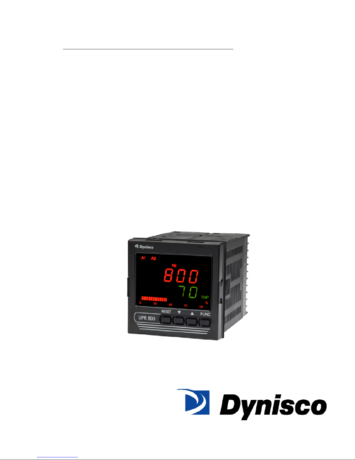
UPR800 Series
Process Indicator
1/4 DIN Panel Display of Pressure and Temperature
P/N: 974144
REV: 04/10
ECO #: 36299
Page 2

DYNISCO UPR800 Series Instruction Manual
Page | 2
Table Of Contents
QUICK START INSTRUCTION .................................................................................................................. 5
Mounting ........................... ...................... ......................... ...................... ......................... ....................... 5
Wiring .................................................................................................................................................... 6
Scaling ........................... ................. ................... ................. ................ .................... ................. .............. 6
Calibration and Operation ....................................................................................................................... 6
1.0 INTRODUCTION ................................................................................................................................. 7
2.0 SPECIFICATIONS ............................................................................................................................... 8
2.1 Mechanical Specifications ................................................................................................................ 8
2.2 Main Power Supply & Environmental Specification .......................................................................... 8
2.3 Display Specifications ...................................................................................................................... 9
2.4 Primary Input ................................................................................................................................. 10
2.5 Secondary Input (optional) ............................................................................................................. 11
2.6 Primary & Secondary Analog Inputs Common ............................................................................... 13
2.7 Digital Input Specification .............................................................................................................. 13
2.8 Alarms ........................................................................................................................................... 13
2.9 Optional Serial Communication Interface Specification .................................................................. 14
2.10 Main Analog Output Specification ................................................................................................ 14
2.11 Second Analog Output Specification ............................................................................................ 15
2.12 Primary & Secondary Analog Outputs Common Specification ...................................................... 15
3.0 UNPACKING ..................................................................................................................................... 17
4.0 DIMENSIONAL INFORMATION ........................................................................................................ 18
5.0 HARDWARE ..................................................................................................................................... 19
6.0 MOUNTING AND WIRING ................................................................................................................ 20
6.1 Terminal Assignments ................................................................................................................... 22
6.2 UPR700 to UPR800 Wiring Conversion Table ............................................................................... 23
7.0 START-UP PROCEDURE ................................................................................................................. 28
7.1 Getting Ready: .............................................................................................................................. 28
7.2 Configuring the UPR800: ............................................................................................................... 28
7.3 Keyboard Description: ................................................................................................................... 29
7.4 Operating Mode Description: ......................................................................................................... 29
8.0 CONFIGURATION ............................................................................................................................ 31
8.1 Parameters ................................................................................................................................... 31
8.2 Parameter Configuration Procedures ............................................................................................. 31
8.2.1 Setting the Logic Input Configuration (if supplied) ....................................................................... 32
8.2.2 Setting the Logic Input Status (if supplied) .................................................................................. 32
8.2.3 Setting Peak Detection ............................................................................................................... 32
8.2.4 Setting the Line Frequency ......................................................................................................... 32
8.2.5 Setting the Display Filter ............................................................................................................. 33
8.3 Primary Input Setup ....................................................................................................................... 34
8.3.1 Setting the Primary Input Type for a Strain Gage Transducer ...................................................... 34
8.3.2 Setting the Shunt Calibration for Strain Gage Transducers and Amplified units ........................... 34
8.3.3 Setting the Primary Input Type for an Amplified Transmitter ........................................................ 34
8.3.4 Setting the Primary Input Full-Scale Value .................................................................................. 35
8.3.5 Setting the Primary Input Low-Scale Value ................................................................................. 35
8.3.6 Setting the Primary Input Decimal Place ..................................................................................... 36
8.3.7 Setting the Primary Input Failsafe Mode ..................................................................................... 36
8.4 Secondary Input Setup .................................................................................................................. 36
8.4.1 Setting the Secondary Input Type ............................................................................................... 36
8.4.2 Setting the Secondary Input Scale and Decimal Point ................................................................. 36
Page 3

DYNISCO UPR800 Series Instruction Manual
Page | 3
8.4.3 Setting the Thermocouple Type and Units: ................................................................................. 37
8.4.4 Setting the Secondary Input Failsafe Mode ................................................................................. 37
8.5 Setting the Alarms: ......................................................................................................................... 38
8.5.1 Setting Channel Alarm to Monitor (Alarm Input Channel Link): .................................................... 38
8.5.2 Setting Alarm Type: .................................................................................................................... 38
8.5.3 Setting the Filtering for Alarm 1: .................................................................................................. 39
8.5.4 Setting the Hysteresis for Alarm: ................................................................................................. 39
8.5.5 Setting the Reset Mode for Alarms: ............................................................................................ 39
8.5.6 Setting the Failsafe Mode for Alarms: ......................................................................................... 40
8.5.7 Setting the Alarms Value (Alarms Threshold): ............................................................................. 40
8.5.8 Setting the Alarms Mask Reset Type: ......................................................................................... 40
8.6 Main Analog Output Setup ............................................................................................................. 40
8.6.1 Setting the Main Analog Output Type .......................................................................................... 41
8.6.2 Setting the Main Analog Output Link ........................................................................................... 41
8.6.3 Setting the Main Analog Output Range Low ................................................................................ 41
8.6.4 Setting the Main Analog Output Range High ............................................................................... 41
8.6.5 Setting the Main Analog Output Filter .......................................................................................... 41
6.5 Setting the Security Codes: ........................................................................................................... 42
8.7.1 Setting the Security Codes for Level A ........................................................................................ 42
8.7.2 Setting the Security Codes for Level B ........................................................................................ 42
8.7.3 Setting the Security Codes for Level C ........................................................................................ 43
8.7 Configure Differential Pressure ...................................................................................................... 43
8.8 Configure by Remote PC (Configuration Port Interface or CPI) ...................................................... 48
9.0 OPERATION ..................................................................................................................................... 50
9.1 Primary Input Calibration ............................................................................................................... 50
9.1.1 Calibration of Pressure Transducers Equipped with an Internal Shunt Resistor ........................... 50
9.1.2 Calibration of Amplified Pressure Transmitters with an Internal Shunt Resistor ........................... 50
9.1.3 Calibration of Pressure Transducers with External Shunt Resistors ............................................. 50
9.1.4 Calibration of Analog Inputs Using a Pressure Calibration Source ............................................... 51
9.1.5 Calibration of the UPR800 to Calibrated Linear Analog Input ...................................................... 51
9.2 Instrument Calibration ................................................................................................................... 52
9.2.2 General Calibration Procedure .................................................................................................... 52
9.3 RS-485 (Optional) ......................................................................................................................... 55
9.3.1 Serial Communication Interface Address .................................................................................... 55
9.3.2 Protocol Type ............................................................................................................................. 56
9.3.3 Communication Type ................................................................................................................... 56
9.3.4 Communication Baud Rate ......................................................................................................... 56
10.0 ERROR CODES .............................................................................................................................. 57
10.1 Error Codes and Troubleshooting ................................................................................................ 57
10.2 “OPEN” Error Code and Troubleshooting ..................................................................................... 58
10.3 Instrument Maintenance .............................................................................................................. 58
11.0 NORMATIVE REFERENCES .......................................................................................................... 60
12.1 Group 1 Parameters .................................................................................................................... 63
12.2 Group 2 Parameters .................................................................................................................... 65
12.3 Group 3 Parameters .................................................................................................................... 67
12.4 Group 4 Parameters .................................................................................................................... 71
12.5 Group 5 Parameters .................................................................................................................... 75
12.6 Group 6 Parameters .................................................................................................................... 76
13.0 WARRANTY AND SERVICE: ........................................................................................................... 78
Page 4

DYNISCO UPR800 Series Instruction Manual
Page | 4
Page 5
DYNISCO UPR800 Series Instruction Manual
Page | 5
QUICK START INSTRUCTION
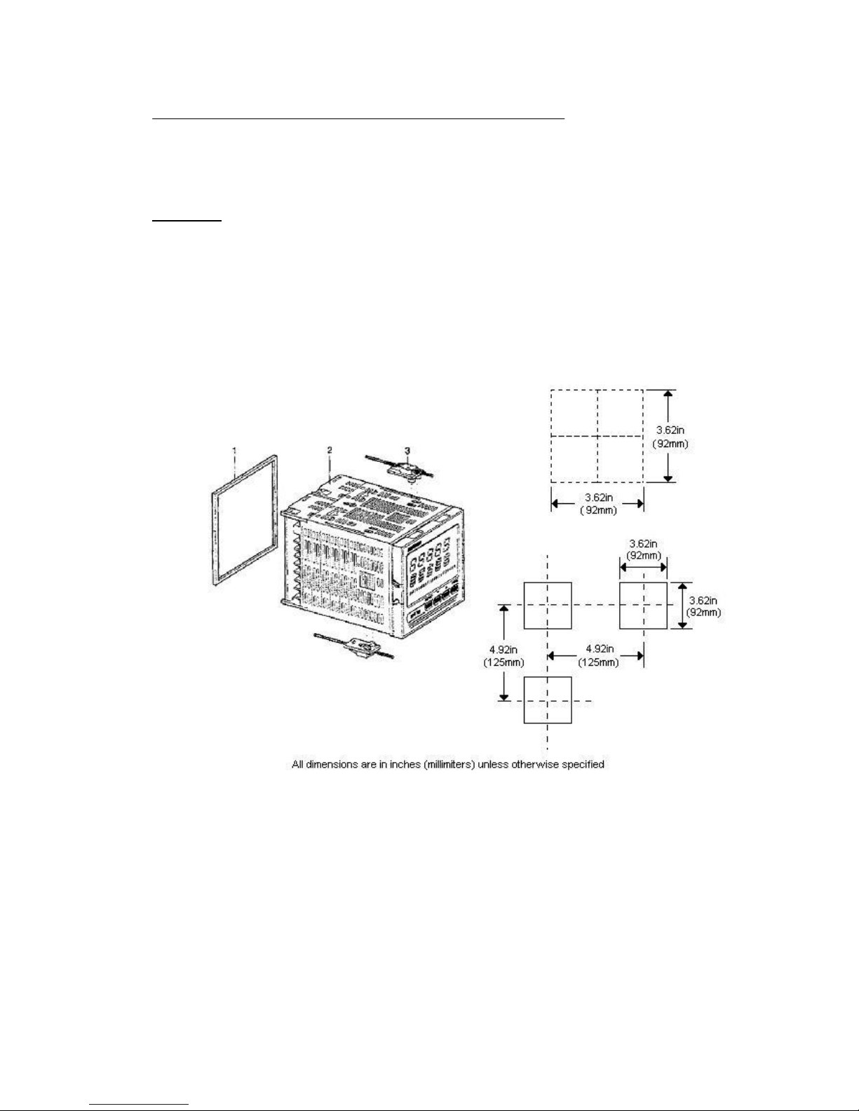
Mounting
• Prepare panel cutout to dimensions shown below.
• If more instruments are mounted in the same panel near together, maintain
the distances between one instrument to another like as in the figure.
• Slide the rubber gasket (1) over the case.
• Slide the instrument case into the cutout.
• Attach the panel mounting hardware tightening the threaded rod (3) for a
secure fit and with a screwdriver, turn the screws with a torque between 0.3
and 0.4 Nm.
Page 6

DYNISCO UPR800 Series Instruction Manual
Page | 6
Wiring
• Connect the wires from transducer cable as shown in the terminal diagram,
turn the screws with a torque between 1.0 and 1.2 Nm.
• Connect an appropriate length of thermocouple extension wire (Type J) to the
connector.
• Connect the thermocouple to the appropriate terminals (remember that red is
negative).
• Connect alarm(s) if applicable. Note that alarm defaults are High, Reverse
Acting.
• Connect power to the appropriate terminals as shown.
Scaling
• Apply power to the instrument; Upper display will give a reading near zero.
Lower display will read the actual temperature.
• Press FUNC key until the Upper display reads NONE.
Lower display reads GROUP.
• If your transducer is not a 10,000-psi model, select Group 3 using the Up
arrow, enter with function key.
• Lower display reads PI.FSV (Full Scale Value), and the upper display reads
10,000. Note: If your transducer is a 10,000 psi model skip next two steps.
Scroll to GROUP.
• Using the Down arrow key set the appropriate Full Scale Value for your
transducer.
• Enter using the FUNC key to scroll until GROUP legend appears again.
• Using Up arrow key, select GROUP 2.
Calibration and Operation
• Lower display reads ZERO.C and upper display reads OFF. Be sure
transducer is at operation temperature and that no pressure is
applied.
• Change upper display to ON by using the Up arrow key. Enter with
the FUNC key. After a few seconds, the lower display will show
SPAN.C and upper display will show OFF.
• Change upper display to ON using Up arrow key. Enter with the
FUNC key. In a few seconds lower display shows DSP.FL and
upper display shows 0.4. Calibration is complete.
• Using the FUNC key, scroll to the GROUP display. Enter 1 with the
Up arrow, and enter with the FUNC key. Instrument shows 0 (±10)
on upper display and temperature on lower display. System is ready
for use.
References to Profibus features and instructions should be ignored. Profibus is being
considered for a future line expansion and has been accommodated in the current design.
Page 7

DYNISCO UPR800 Series Instruction Manual
Page | 7
1.0 INTRODUCTION
The UPR800 Pressure/Process Indicator is a microprocessor-based instrument, with the
capability of monitoring one or two process variables simultaneously. The primary input is
user configurable to be 350K Strain Gage, high-level voltage or high level current. If the
second input option is chosen, it is configurable by the user as any of four thermocouples,
PT-100 RTD, high-level voltage or high level current. They are compatible with many
process transmitters and can be scaled by the user to give an appropriate range in
engineering units. The UPR800, in its dual input version, can provide simultaneous
readout of common process variable pairs such as Pressure and Temperature,
Temperature and Humidity, etc., when used with the appropriate sensor / transmitter
combinations. Pressure value input and retransmission output groups are selected
though the keypad. Thus the need to make numerous selections within the instrument is
minimized. The UPR800 is provided with two alarms and an analog retransmission
output any of which can be assigned to the primary or secondary input. A second analog
retransmission output is available as an option, as is a 24Vdc power supply for two and
four wire process transmitters. A third alarm is also available as an option.
Five groups of configuration parameters are available from the keyboard, and are
protected by three levels of user definable software locks. The displays can be single-line
(primary input only; lower display blanked), dual line with primary input in the upper
display and high or low peak in the lower display, or dual display of primary input in the upper display and secondary input in the lower display. In the last mode, the lower display
can alternate between the secondary input and the primary input peak value via
keystroke. In addition, a red LED bar graph presents an analog representation of the
primary input, as well as indication of the alarm set points.
References to Profibus features and instructions should be ignored. Profibus is being
considered for a future line expansion and has been accommodated in the current design.
WARNING NOTE: The user should be aware that if this equipment is used in a
manner not consistent with the specifications and instructions in this manual, the
protection provided by the equipment might be impaired.
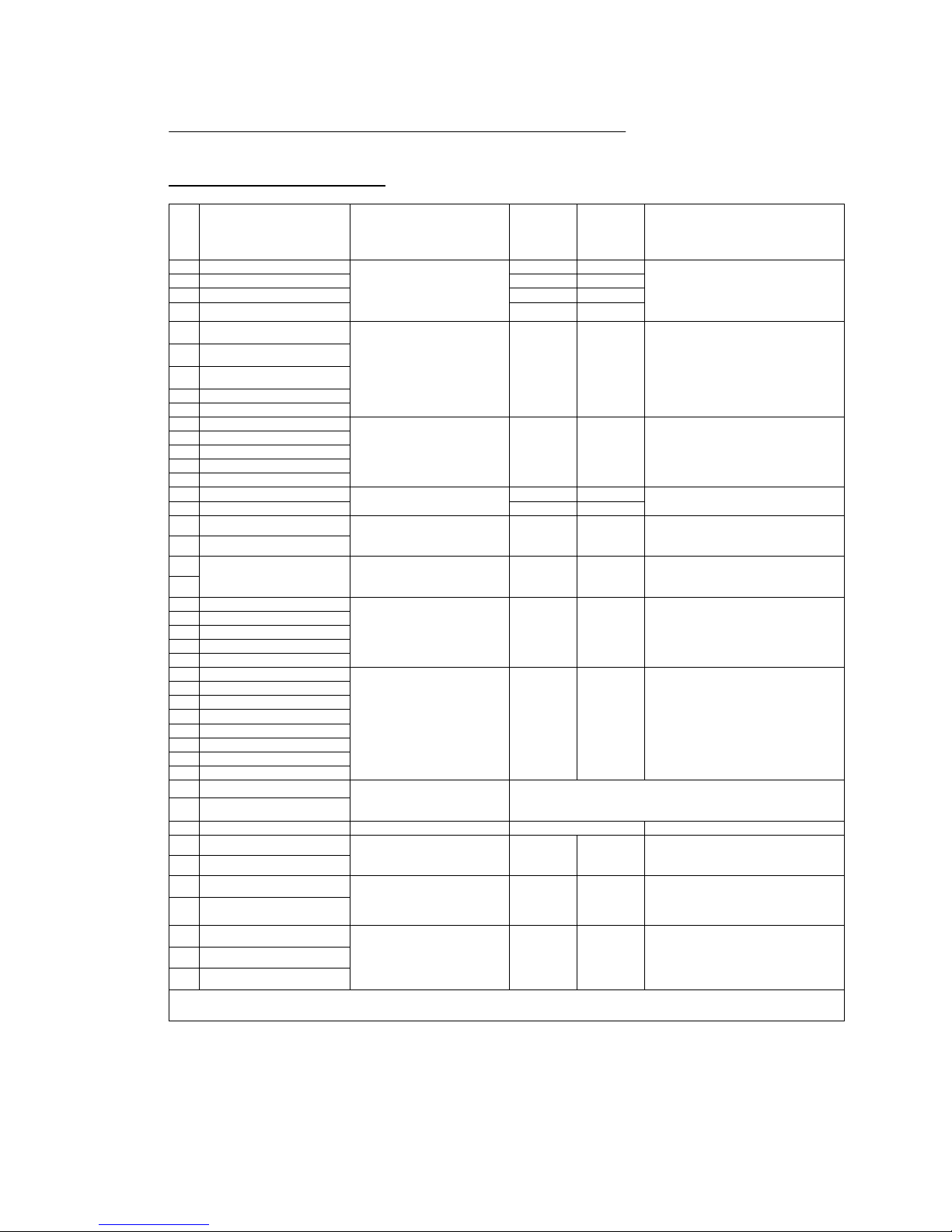
Product (Model) Codes
Model
Input
Options
Power
Code Descriptio
n
Code Description
Code Voltage
0 Not Present 0 No Option 3 100-240 Vac (switching)
UPR800-
1 T/C, RTD, mV,
mA/V
2 24 Vdc transmitter power
supply and 2
nd
analog
retransmission.
5 24 Vac/Vdc (switching)
3 24 Vdc transmitter power
supply and 2nd analog
retransmission & RS-485
Instruments with the suffix - A3 after the model number have the optional third alarm.
Page 8

DYNISCO UPR800 Series Instruction Manual
Page | 8
2.0 SPECIFICATIONS
2.1 Mechanical Specifications
Case: Polycarbonate Black color Self-extinguishing degree VO according to UL 94
Front Panel: Designed and verified for IP65 and NEMA 4X for indoor location
Installation: Panel mounting
Rear Terminal Block: 43 screw terminals with rear safety cover
2.2 Main Power Supply & Environmental Specification
Main Power Supply: From 100 to 240Vac (-15% to 10%), 50/60 Hz switching. Option:
24Vac/dc
Power supply variation: From -15% to 10% (for 100 to 240Vac). From 14 to 32 Vdc or
from 14 to 30 Vac (for optional 24Vac/dc).
Power Consumption: 15VA, max.
Insulation Resistance: 100 MN @500Vdc
Dielectric Strength: 1500V rms for 1 min, 1800V for 1 sec
Ambient Temperature: From 0 to 50°C
Storage Temperature: From -20 to 70°C
Humidity: Max 85% RH non-condensing
Watchdog: Hw/Sw is provided for automatic restart
Agency Approvals: UL File # 193253
Self-Certification: CE
Electromagnetic Compatibility and Safety Requirements: The instrument is CE
Marked. It is compliant with the European Directive 2004/108/CE according to Product
Standard EN 61326-1.
Emission limit: class A – group 1 ISM for equipment suitable for use in all
establishments other then domestic and those directly connected to a
low voltage power supply network which supplies buildings used for
domestic purposes.
Immunity:
Page 9

DYNISCO UPR800 Series Instruction Manual
Page | 9
• Electrostatic discharge (according to EN 61000-4-2):
contact discharge = 4kV; air discharge = 8kV
• Radio-frequency electrical magnetic (according to EN 61000-4-3):
EM field (amplit. mod.) = 10 V/m (80 MHz to 1 GHz);
3V/m (1,4 GHz to 2 GHz);
1 V/m (2 GHz to 2,7 GHz)
• Electrical fast transient/burst (according to EN 61000-4-4):
AC Power = 2kV;
I/O Signal/Control = 2kV (5/50 ns, 5 kHz);
I/O Signal/Control connected directly to mains supply = 2kV (5/50 ns,
5 kHz)
• Surge (according to EN 61000-4-5):
AC power = 1kV (Line to Line) / 2kV (Line to GND);
I/O Signal/Control (analog inputs excluded) = 1kV (Line to Line) / 2kV
(Line to GND)
• Radio frequency common mode (according to EN 61000-4-6):
AC Power = 3 V (150kHz to 80 MHz);
I/O Signal/Control = 3 V (150kHz to 80 MHz)
• Voltage dips/short interruptions (according to EN 61000-4-11):
0% during 1 cycle; 40% during 12 cycles; 70% during 30 cycles
This equipment is intended for use in an industrial location. There may be potential
difficulties ensuring electromagnetic compatibility in other environmental due to conducted
as well as radiated disturbances.
Safety Requirements:
The instrument is compliant with the European Directive 2006/95/CE according to
Reference Standard EN 61010-1 for installation category I and pollution degree 2
Installation category CAT I: Voltage transients on any power connected to the
instrument must not exceed 1.5kV.
Pollution degree 2: Conductive pollution must be excluded from the
cabinet in which the instrument is mounted.
2.3 Display Specifications
Display: LED technology, custom type.
Upper Digits: Red color, 5 numeric digits, 7 segments with decimal point 13.2mm high.
Lower Digits: Green color, 5 alphanumeric digits (British flag), 14 segments with decimal
points. 11.3mm high.
Bar Graph: Red color, 35 segment with 3% resolution. Displays continuous bar graph to
indicate the measured variable of the primary input (0-100% full scale). Alarm set point
values displayed. Last segment blinks for pressure greater than full scale value.
Page 10

DYNISCO UPR800 Series Instruction Manual
Page | 10
Indicators (Beacons):
Red
LED’s annunciations:
• A1: Lit when alarm 1 is in alarm state
• A2: Lit when alarm 2 is in alarm state
• A3: Lit when alarm 3 is in alarm state
• REM: Lit when device is controlled by serial link
• 0-25-50-75-100-%: These six LEDs are always on to improve the bar graph
indication.
• Kg/cm
2
, PSI, Bar, MPa: Engineering unit for the pressure input. These four
beacons are located within the display window, between the numeric digits and the
alarm beacons.
Green
LED’s annunciations:
• PEAK: Lit when lower display shows the peak value
• TEMP: Lit when lower display shows the temperature input value
2.4 Primary Input
Primary Input: Selectable between strain gage and linear by software configuration.
Strain Gage Input: From 340 to 5000K, 1-4mV/V. Excitation 10V ±7%. 5 wire
connection.
Input Signal: -25/125% of full scale (approximately –10 / 50mV).
Shunt Calibration: With or without shunt resistor (value programmable from 40.0 to
100.0%).
Zero Balance: ±25% of full scale (approximately ± 10mV).
Linear Input: Selectable between 0-5Vdc, 0-10Vdc, 0-20mA, 4-20mA.
Auxiliary Power supply: 24Vdc / 1.5W ± 2% power supply for two or four wire
transmitter.
Input Impedance:
<10K for linear current input
>165KK for linear voltage input
Input Protection: Open circuit detection for strain gage (on signal and excitation wires)
and 4-20mA inputs; it is not available for 0-5Vdc, 0-10Vdc and 0-20mA. Up or down scale
keyboard programmable.
Sampling Time: 50mS typical.
Display Update Time: Selectable: 50, 100, 250 or 400mS.
Page 11

DYNISCO UPR800 Series Instruction Manual
Page | 11
Engineering Units: Dedicated beacons within the display window.
Calibration mode: Field calibrations (zero and span) are applicable for both strain gage
and linear input. Moreover it is possible to delete the field calibration done by the end user
and to restore original factory calibration values.
Input resolution: 4000 counts.
Full scale value Resolution
10/4000 1 count
4002/8000 2 counts
8005/20000 5 counts
20010/40000 10 counts
40020/80000 20 counts
80050/99950 50 counts
Decimal Point Settable in any position of the display.
2.5 Secondary Input (optional)
Temperature Input: Selectable between linear, thermocouple or RTD input by software
configuration.
Function: Selectable between: temperature (in case of linear, thermocouple, RTD the
input); second sensor for the measurement of a differential pressure (in case of strain
gage or linear input)
Linear Input: Selectable between 0-5Vdc, 0-10Vdc, 0-20mA, and 4-20mA
Page 12
DYNISCO UPR800 Series Instruction Manual
Page | 12
Sensor Type and Range:
Thermocouple J -200/+800°C -328/+1472°F
Thermocouple K -200/+1200°C -328/+2192°F
Thermocouple L -200/+800°C -328/+1472°F
Thermocouple N 0/1300°C 32/+2372°F
Thermocouple T -200/+400°C -328/+752°F
Thermocouple E -200/+600°C -328/+1112°F
RTD Pt100 -200/+600°C -328/+1112°F
RTD Pt500 -200/+600°C -328/+1112°F
Input Protection: Open circuit detection for strain gage (on signal and excitation wires),
thermocouple, RTD and 4-20mA inputs; not available for 0-10Vdc, 0-5Vdc and 0-20mA
inputs. Up or down scale keyboard.
Input Impedance:
>1MK for thermocouple input.
<10K for linear current input
>165KK for linear voltage input
T/C Lead Length: 100K max.
Reference Junction Compensation: from -20 to 60°C.
RTD measure system: 3 wire.
RTD Lead Length Compensation: Up to 20K/wire for the Pt100 and Pt500.
Sampling Time: Temperature input is selectable among 100, 200, 500 or 1000mS;
differential pressure is 50 mS, typical.
Display Update: At each sample.
Input Resolution with Linear Input: 4000 counts.
Low/High Scale Values: From -1000 to 3000, linear inputs only. Secondary differential
pressure is selectable, but with the same resolution and decimal point position of the
primary pressure input.
Decimal point: Settable in any position.
NOTE: These secondary inputs are not isolated from the primary input. A double or
reinforced insulation between instrument output and power supply must be guaranteed by
the external device.
Page 13

DYNISCO UPR800 Series Instruction Manual
Page | 13
2.6 Primary & Secondary Analog Inputs Common
Common Mode Rejection Ratio: >120dB @50/60Hz
Normal Mode Rejection Ratio: >60dB @ 50/60Hz
Strain gage input: From 340 to 5000K, 1-4 mV/V. Excitation 10V +/- 7%. 5 wires
connection.
Input signal: -25/125% of full scale (approximately -10/50mV).
Shunt calibration: With or without shunt resistor (value programmable from 40.0 to
100.0%), the same setting will be used for both inputs (main and secondary) when the
differential pressure measurement is selected.
Zero balance: +/- 25% of full scale (approximately +/- 10mV).
Reference accuracy: +/- 0.1% FSV +/-1 digit @ 25 +/- 1°C and nominal power supply
voltage.
Operative accuracy: temperature drift:
• < 200 ppm/K of full span (RJ excluded) for TC input.
• < 300 ppm/K of full span for current, voltage and strain gage input.
• < 400 ppm/K of full span for RTD input.
• < 0.1K/K for reference junction.
Zero and span calibration: If differential input used, there is no relation between the
calibration of the two single sensors; each input is provided with its own zero and span
calibration parameters.
Wiring caution: The analog input lines cannot exceed the 30 meter length or leave the
building.
2.7 Digital Input Specification
Digital input: One input from contact closure (voltage free). It may be keyboard
programmable for the following functions:
• Alarm reset
• Peak reset
• Alarm and peak reset
NOTE: This input is not isolated from primary input. A double or reinforced insulation
between instrument output and power supply must be guaranteed by the external device.
2.8 Alarms
Alarm Outputs: 2 standard alarms (AL1 and AL2). 1 optional alarm (AL3).
Page 14

DYNISCO UPR800 Series Instruction Manual
Page | 14
AL1 and AL2 Contacts: 1 SPDT 2A max 0 240Vac resistive load.
AL3 Contacts: 1 SPST selectable NO/NC 2A max @ 240Vac resistive load.
Contact Protection: Varistor for spike protection.
Alarm Type: Each alarm is keyboard programmable for:
• Primary/Secondary input
• High/Low/Low inhibited on start up
• Auto/Manual reset
Excitation Type: Keyboard configurable for each alarm: relay coil energized in no alarm
condition (failsafe) or relay coil energized in alarm condition (non-failsafe).
Threshold: From 0 to 110% Full Scale (the threshold may be limited due to the selected
full scale value).
Hysteresis: Keyboard programmable for each alarm; from 0.1% to 10.0% of span or 1
LSD (whichever is greater) for each alarm.
Filter: Selectable from the following values for each alarm:
OFF, 0.4S, 1S, 2.5S, 3S, 4S, 5S.
Alarm Update Time: At every input conversion.
2.9 Optional Serial Communication Interface Specification
Serial Interface: RS-485 type. Opto-isolated.
Protocol Type: Modbus/Jbus (RTU mode).
Type of Parameters: Run-time and configuration are available by serial link.
Device Address: From 1 to 255
NOTE: The physical interface can only support up to 31 devices for each
segment. Use multiple segments for more than 31 devices.
Baud Rate: 600 up to 19200 baud.
Format: 1 start bit, 8 bits with/without parity. 1 stop bit
Parity: Even/Odd.
2.10 Main Analog Output Specification
Main Analog Output: Opto-isolated from CPU input and output circuits.
Page 15

DYNISCO UPR800 Series Instruction Manual
Page | 15
Type of Output Function: Keyboard selectable as
• Primary input retransmission
• Secondary input retransmission
Type of Analog Output: Keyboard selectable between:
• +0/10Vdc min. load 5 KN, with under/over range capability from -2.5 to 12.5V
• -10/+10Vdc mm. load 5KN, with under/overrange capability from -12.5 to 12.5V
• +0/5Vdc mm. load 5KN, with under/overrange capability from -1.25 to 6.25V
• +0/20mA max. load 500N, with under/over range capability from -5 to 25mA
(max. load 400N over 20mA).
• +4/20mA max. load 500N, with under / over range capability from 0 to 24mA
(max. load 400N over 20mA).
2.11 Second Analog Output Specification
Second Analog Output: Opto-isolated from CPU input and output circuits.
Type of Output Function: Keyboard selectable for:
• Primary input retransmission
• Secondary input retransmission
Type of Analog Output: Keyboard selectable between:
• +0/10Vdc min. load 5KN, with under/over range capability from -2.5 to 12.5V
• +0/5Vdc min. load 5 KN, with under/over range capability from -1.25 to 6.25V
• +0/20mA max. load 500N, with under/over range capability from 0 to 24mA
(max. load 400N over 20mA).
• +4/20mA max. load 500N, with under/over range capability from 0 to 24mA
(max. load 400N over 20mA).
2.12 Primary & Secondary Analog Outputs Common Specification
Resolution: 0.1% of output span.
Reference Accuracy: ±0.1% of output span @ 25 ± 1°C and nominal line voltage.
Linearity Error: <0.1% of output span.
Output Noise: <0.1% of output span.
Scaling: The retransmission low and high limits are selectable from 0 to primary input
full-scale value (when the retransmitted variable is primary input) or from low to high
secondary limits (when the retransmitted variable is the secondary input). The two scaling
values may be freely selectable within the above range. This allows having a direct or
reverse output type.
Output Filter: Selectable: OFF, 0.4S, 1S, 2S, 3S, 4S, 5S
Page 16
DYNISCO UPR800 Series Instruction Manual
Page | 16
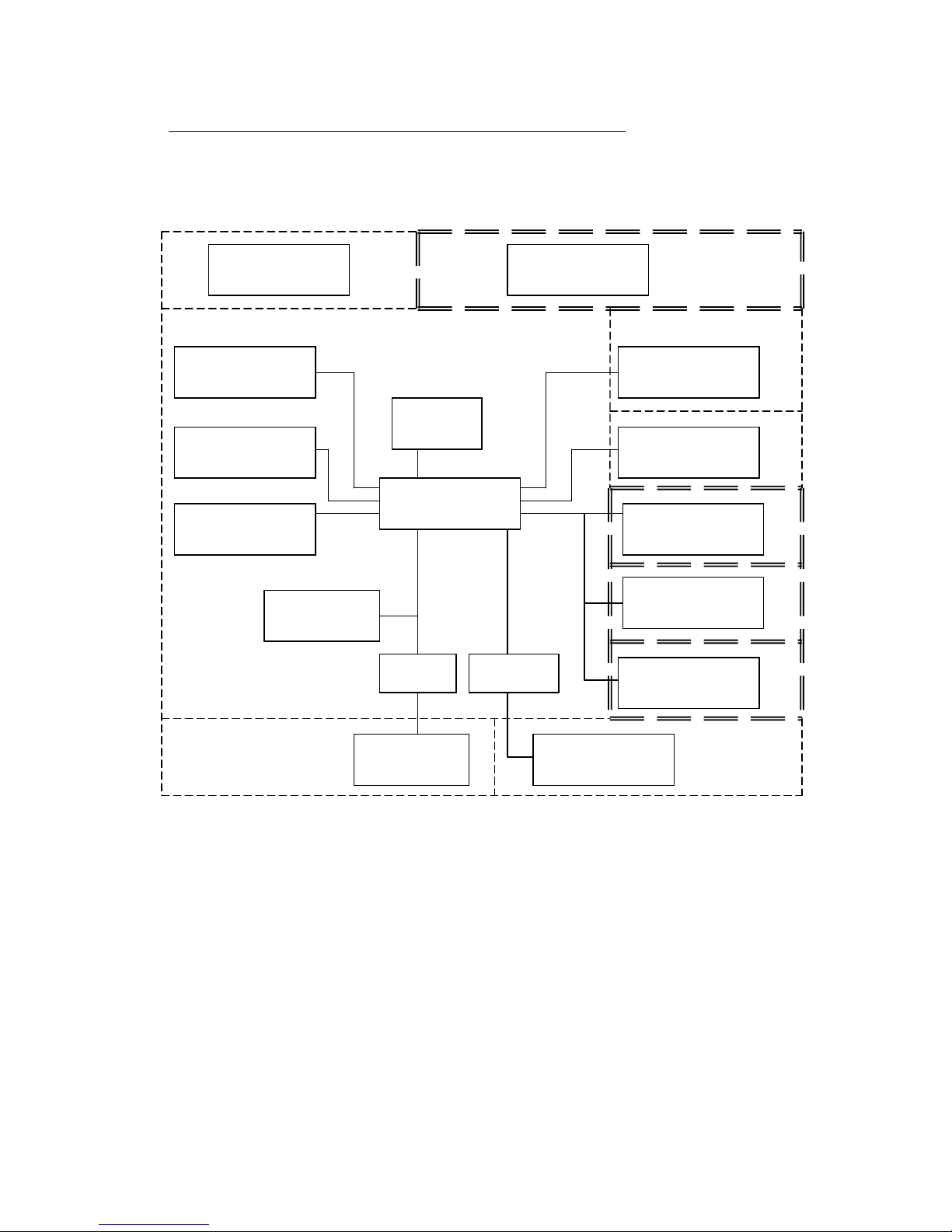
NOTE: Dashed Line represents insulation boundary.
Double Dashed Line represents reinforced insulation boundary.
AUXILIARY
POWER SUPPLY
MAIN
POWER SUPPLY
MAIN
ANALOG
OUTPUT
SECONDARY
ANALOG
OUTPUT
ALARM 1
OUTPUT
CPI
Configuration Port
Interface
ALARM 3
OUTPUT
(option)
MAIN
ANALOG INPUT
Strain gage and Linear
DISPLAY
KEYBOARD
CPU
RS485
INTER FACE
PROFIBUS
DP
INTERFACE (NA)
SECONDARY
ANALOG INPUT
Tc, RTD and Linear
RESET
Logic Input
MODBUS
RTU
PROFIBUS
DP Module (NA)
ALARM 2
OUTPUT
Page 17

DYNISCO UPR800 Series Instruction Manual
Page | 17
3.0 UNPACKING
Upon receipt, examine package for shipping damage. Notify the carrier immediately in the
event of any evidence of damage, and retain shipping materials for their inspection.
This package should contain the instrument and two panel mounting brackets.
Page 18

DYNISCO UPR800 Series Instruction Manual
Page | 18
4.0 DIMENSIONAL INFORMATION
Dimensions: 3.78” X 3.78” X 6.01” overall (96mm X 96mm X 143.5mm)
Cutout: 3.62” X 3.62” (92mm X 92mm)
Depth behind panel: 5.04” (128mm)
Weight: 1.43 lbs. (650g)
Page 19

DYNISCO UPR800 Series Instruction Manual
Page | 19
5.0 HARDWARE
The UPR800 is shipped configured for the following:
• Primary Input (Pressure) - Strain Gage
• Optional Secondary Input - Thermocouple
• Main Output - Voltage
• Optional Secondary Output – Voltage
• Security lock is OFF
Please refer to the drawings in the appropriate sections to determine the configuration for
input(s) and output(s) used in your particular application. It is necessary only to select the
category (e.g. Voltage or Current). The specific range will be chosen in the software
menu.
Page 20

DYNISCO UPR800 Series Instruction Manual
Page | 20
6.0 MOUNTING AND WIRING
Please refer to figures for cutout dimensions and clearance requirements. Locate the two
mounting brackets packed with the instrument and have them available.
1. Slide the instrument case into the cutout, being sure that it is right-side-up (terminal 1
at the top). Attach the panel mounting hardware at diagonally opposite sides of the top
and bottom of the case, tightening the threaded rod until the case is secure against
the panel.
2. Refer to the model number of the instrument to determine the hardware and options
included as part of your unit. Please refer to Section 6.1 for the terminal assignments.
Terminals are accessed by opening the terminal covers from the side with the “OPEN”
legend.
NOTE 1: The UPR800 is equipped with screw terminals, and no connectors are
necessary when wiring the unit
NOTE 2: When wiring the alarms, wire to the Common and NO (normally open) terminals
to maintain a fail-safe configuration.
Fail-safe denotes a situation where the alarms relay coils are activated in a no-alarm
situation. As the relay coil is energized, terminals that are normally open are closed and
can cause completion of a circuit when used as an interlock. Should the alarm threshold
be exceeded, OR should power be lost to the instrument the contacts will open, and the
circuit will be broken. If the alarm is a latching alarm, it will require an external reset signal
to be activated again.
If the alarm is used to provide a contact to an alarm device (light, horn buzzer, etc., when
the threshold is exceeded, wiring should be to the Common and NC (normally closed)
terminals. Activation of the relay coil will cause the contacts to open in a non-alarm
situation, and to close if the threshold is exceeded, or power is interrupted to the
instrument. If the alarm is a latching alarm, it will require an external reset signal to be
activated again.
NOTE 3: Relay Outputs
The contact rating of all outputs is equal to 2A/240 Vac on resistive load.
• To avoid electrical shock, connect power line at the end of the wiring procedure.
• For power connections use No 16AWG or larger wires rated for at least 75°C.
• Use copper conductors only.
NOTE 4: Power Line
Before connecting the instrument to the power line, make sure that the line voltage
corresponds to the description on the identification label.
Page 21

DYNISCO UPR800 Series Instruction Manual
Page | 21
• To avoid electrical shock, connect power line at the end of the wiring procedure.
• For supply connections use No. 16AWG or larger wires rated for at least 75°C.
• Use copper conductors only.
• Don’t run input wires together with power cables.
• When a neutral line is present, please connect it to terminal 54.
• For 24Vdc the polarity need not be observed.
The power supply input is fuse protected by a sub miniature fuse rated T, 250V, 1A (2A
for the optional 24Vac/dc).
When the fuse is damaged, it is advisable to verify the power supply circuit. It is
necessary to send back the instrument to Dynisco for service.
The safety requirements for Permanently Connected Equipment say:
• A switch or circuit-breaker shall be included In the building installation;
• It shall be in close proximity to the equipment and within easy reach of the operator
• It shall be marked as the disconnecting device for the equipment.
• A single switch or circuit breaker can drive more than one Instrument
• Protective conductor terminals shall be connected to earth.
Page 22
DYNISCO UPR800 Series Instruction Manual
Page | 22
6.1 Terminal Assignments
Terminal
Terminal
Assignment Description
Function
category / class
Voltage
Rating,
V
Current
Rating,
A
Load type and Rating
1 RTD, T/C +
Secondary Inputs
CAT I
2 Vdc 0.001 Adc
3 RTD, T/C -, mA/V -
4 mA +, RTD compensation 0.020 Adc
5 V + 10 Vdc
6 SIG +
Secondary Input Strain
Gage
CAT I
From 340N to 5000N,
Excitation 10Vdc ±7% (between
EXC + and EXC -)
7 SIG -
8 CAL2
10 EXC +
11 EXC - , CAL1
12 SIG +
Main Input Strain Gage
CAT I
From 340N to 5000N,
Excitation 10Vdc ±7% (between
EXC + and EXC -)
13 SIG -
14 CAL2
16 EXC +
17 EXC - , CAL1, mA -, V -
18 mA +
Main Linear Inputs
CAT I
0.020 Adc
19 V + 10 Vdc
21 OUT1 mA/V +
Main Analog
Retransmission
Class 2
±12.5 Vdc min load 5KN.
-5/+25 mA max load 500N
(max. load 400K over 20 mA).
22 OUT1 mA/V -
23
RESET
Remote Reset of Alarm
and/or peak
Class 2
Dry Contact switch
(voltage free)
24
29 SHIELD
Standard ProfiBus
Communication
Class 2
30 5VP
31 B/B’
32 A/A’
33 DGND
45 ALARM1 N.O.
Relay contacts used to
identify an event (alarm)
condition
240 Vac, 2A , resistive
46 ALARM1 C
47 ALARM1 N.C
48 ALARM2 N.O.
49 ALARM2 C
50 ALARM2 N.C.
51 ALARM3 C
52 ALARM3 N.C./N.O.
53
Line ~ or +
Main Power Supply
(according to the Product Code)
100 – 240Vac
27VA maximum
or
24Vdc, 12W maximum
24Vac, 18VA maximum
Class 2
54
Neutral
~ or -
55 Earth (Ground)
56 OUT2 mA/V +
Secondary Analog
Retransmission
Class 2
±12.5Vdc min load 5KN.
-5/+25 mA max load 500N
(max. load 400K over 20 mA).
57 OUT2 mA/V -
58 Vdc SUPPLY +
Auxiliary Power Supply
Class 2
24 Vdc
0.063 Adc
(1.5W)
59 Vdc SUPPLY -
60 A/A’
Serial Communication
RS485
Class 2
61 B/B’
62 C
Note:
The instrument is not suitable for use with equipment for measurement within measurement categories II, III and IV.
Page 23
DYNISCO UPR800 Series Instruction Manual
Page | 23
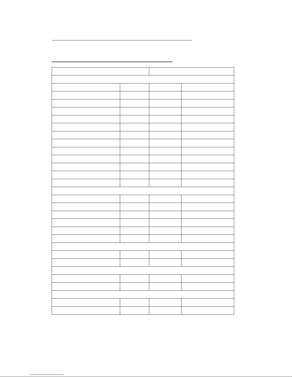
6.2 UPR700 to UPR800 Wiring Conversion Table
UPR800 Terminal UPR700 Terminal
Power
100 - 240Vac or 24Vac/dc 53 53
Line Neutral 54 54
Earth (Ground) 55 55
Transducer Dynisco Cable Color
Signal (+) 12 12 Red
Signal (-) 13 13 Black
Excitation (+) 16 16 White
Excitation (-) 17 17 Green
CAL 1 17 17 Blue
CAL 2 14 14 Orange
mA (+) 18 12
V (+) 19 12
mA/V (-) 17 13
Alarms
A1 (N.O.) 45 45
A1 Common 46 46
A1 (N.C.) 47 47
A2 (N.O.) 48 48
A2 Common 49 49
A2 (N.C.) 50 50
Alarm 3 (optional)
A3 (N.O. / N.C.) 52 52
A3 Common 51 51
Analog Output
mA/V Out (+) 21 21
mA/V Out (-) 22 22
2nd Analog Output (optional)
mA/V Out (+) 56 56
mA/V Out (-) 57 57
Page 24

DYNISCO UPR800 Series Instruction Manual
Page | 24
UPR800 Terminal UPR700 Terminal
24 VDC Transmitter Power Supply (optional)
24 Vdc (+) 58 58
24 Vdc (-) 59 59
External Reset Contacts
Reset 23 23
Reset Common 24 24
Second Analog Input (optional)
Thermocouple Input
TC (+) 1 1
TC (-) 3 3
mA Input
lnput (+) 4 4
lnput (-) 3 3
V Input
lnput (+) 5 4
lnput (-) 3 3
RTD Input 3-wire
Red 1 1
Black 3 3
Black 4 4
Serial Communications (RS485 only)- (optional)
A 60 60
B 61 61
COM 62 62
Page 25

DYNISCO UPR800 Series Instruction Manual
Page | 25
Page 26

DYNISCO UPR800 Series Instruction Manual
Page | 26
Page 27

DYNISCO UPR800 Series Instruction Manual
Page | 27
Page 28

DYNISCO UPR800 Series Instruction Manual
Page | 28
7.0 START-UP PROCEDURE
In general, the UPR800 Pressure/Process Indicator is a microprocessor-based
instrument, with the capability of monitoring one or two process variables simultaneously.
The primary input is configured to accept a 350N Strain Gage, but can be changed to
accept high level voltage or current. The primary input full-scale value can be as low as
10, and as high as 99,950 units. The secondary input, if supplied, will accept a “J” type
thermocouple, but can be changed to most thermocouples or RTD’s, or to a high-level
voltage or current. The secondary input full-scale value can be as low as -1,000 and as
high as 3,000 units.
The standard UPR800 has 2 SPDT dry contact closure alarms, with an optional third
alarm. In addition, it has one or two scalable analog retransmission outputs, or RS-485
communications.
Alarm 1 is configured as a High Alarm at 40% of the full-scale transducer value, with 0.4
second filtering, 1.0% hysteresis, Auto reset, failsafe mode, and it is linked to the primary
input.
Alarm 2 is configured as a High Alarm at 60% of the full-scale value, with 0.4 second
filtering, 1.0% hysteresis, Auto reset, failsafe mode, and is also linked to the primary
input,
Alarm 3, if supplied, is configured as a High Alarm at 80% of the full-scale value, with 0.4
second filtering, 1.0% hysteresis, Auto reset, failsafe mode, and it is disabled (not linked
to any input),
These terms will be described in the ALARMS section.
7.1 Getting Ready:
1. Slide the case into the panel cutout. MAKE SURE TERMINAL 1 IS AT THE TOP!
Attach the panel mounting hardware at diagonally opposite sides of the top and
bottom of the case, tightening the threaded rod until the case is secure against the
panel.
2. Attach the primary and secondary devices, (if supplied) and wire according to the
terminal assignments.
7.2 Configuring the UPR800:
Apply power to the cabinet. The upper display will show a reading near zero, and the
lower display will show the current temperature or PEAK if the unit does not have
secondary input. It may display OPEN if there is no transducer connected, or if the
transducer is amplified.
Page 29

DYNISCO UPR800 Series Instruction Manual
Page | 29
The keys on the UPR800 must be pressed and released to move about in the configure
screens. Do not press and hold a key unless told to do so; simply press the key and
release it to advance to the next screen. The arrow keys u or t may be held down to
advance rapidly through the values.
7.3 Keyboard Description:
The keyboard is composed of four push buttons, covered by a silicone protective
operator, labeled u, t, FUNC and RESET.
The u is called the “Down Arrow Key”, and is used to increment and decrement the
parameter value.
The t is called the “Up Arrow Key”, and is used to increment and decrement the
parameter value. It also may be used to switch the lower display from the secondary
input (if available) to the peak value (if enabled) and back again. At power up, the lower
display shows the secondary input value (if present) or it shows the peak value. If there is
no secondary input and the peak value is disabled, the lower display is blank.
The FUNC (“function”) key is used to access the parameter to view, modify, and enter the
“Operating Mode Switching” procedure (when pressed for more than 7 seconds).
The RESET key is used to reset the stored peak value and to reset the alarms when held
for 1 second, (once the alarm condition has cleared beyond the hysteresis value). This
function is disabled when the device is controlled by the serial link. In addition, when
checking or changing parameters, it is used to return to the normal display mode without
storing the parameter change.
Pressing t then RESET together, or u then, may be used to jump to maximum or
minimum parameter values when the instrument is in function mode.
At power up, if the instrument detects a parameter error, the upper display shows ERR #,
(where # is the error number), and the lower display will show the parameter name. If the
wrong parameter is a run-time parameter (i.e. AL 1 to SO.TYP) pressing the t then u
together will cause the instrument to load the default values for all parameters.
If the wrong parameter is a calibration or code parameter, pressing the FUNC then
RESET keys together, enables the instrument to access the run-time parameters. This
function is intended only to restore a misplaced parameter’s value; however, the
performance of the instrument is not guaranteed. The user is advised to check the stated
parameter.
NOTE: All the actions explained above that require two or more pushbuttons, must follow
the pushbutton sequence exactly.
7.4 Operating Mode Description:
The FUNC key is used to access the parameters organized in five groups. Use the
FUNC pushbutton to access the Group 1 parameters; the last entry (showing Group and
Page 30

DYNISCO UPR800 Series Instruction Manual
Page | 30
None is intended to access the other groups of parameters, or pressing FUNC again
returns to the normal display mode. Each group has its own family of parameters, loosely
grouped around the decreasing need to change the parameters. Each group also has the
ability to load its own default parameters and the default values of the lower number
groups.
Page 31

DYNISCO UPR800 Series Instruction Manual
Page | 31
8.0 CONFIGURATION
8.1 Parameters
The UPR800 parameters are grouped in five sections guarded by three security levels.
The more common parameters are in the first groups, with the higher Group numbers for
those parameters an operator would not normally modify. Each group can be reset to its
default value by two keystrokes. This also resets the parameters of any lower numbered
group to default. If GROUP 5 is set to default, the entire instrument is reset to its default
parameters. If a unit does not have a particular option, its parameters will not appear.
For example, an instrument that does not have RS-485 communications will skip those
parameters related to communications. Likewise, if a particular function is turned off, its
other parameters will not appear. For example, if Alarm 2 is turned to OFF in Group 3, the
hysteresis, reset, filter, type, and threshold functions will not appear on screen. Nor will
the alarm appear on the bar graph display.
When the instrument is turned on, it will go through a self-test during which the front panel
will illuminate. The instrument will then be in the normal display mode showing the value
of the main input on the upper display, and the value of the secondary input on the lower
display (if so equipped). If there is no secondary input, the lower display will show the
maximum peak value of the main input. In the event that no input device is connected,
both displays will show OPEn. If no secondary input is present, the lower display will
show OPEn indicating that the unit failed to full scale, the bar graph display will be at
100% with the last segment flashing. Turn the power to the instrument off and connect an
input device to the appropriate terminals, and connect a thermocouple or appropriate
signal source to the secondary input terminals (if supplied). Upon turning the instrument
back on, the displays should have a numeric value, close to zero pressure on the
pressure display, and near room temperature on the thermocouple display. Depressing
FUNC will go automatically into the GROUP 1 parameters.
Successively pressing FUNC will scroll through all the parameters of GROUP 1. The last
two parameters of each group allow the default parameters to be restored, and returns to
GROUP. If nonE is chosen in the group access function, the instrument will return to
normal operating mode after pressing of the FUNC key.
When in GROUP 1, if no keyboard activity is detected for approximately 10 seconds, the
instrument will automatically return to the normal display mode.
8.2 Parameter Configuration Procedures
The parameters in the five groups are extensive, and not all parameters need to be
addressed. While they are fully explained in the following section, it would be well to
review them prior to configuring the instrument in your application. It is entirely possible
that only a minimum number of parameters need to be adjusted to have your process
operating satisfactorily. Please note that at any time, the default parameters may be
reset to the factory settings. Each parameter group can be reset at any time, (which also
resets the levels with numbers higher than the selected group). To set a default level,
press the FUNC key until DEFLT shows on the lower display and OFF shows on the
Page 32

DYNISCO UPR800 Series Instruction Manual
Page | 32
upper display. Press the u or t key until ON 1 shows in the upper display. Press the
FUNC key to load all of the factory parameters for groups 1, 2, 3, 4, and 5.
To reset a specific group (and higher numbered groups) to the default factory settings,
press the FUNC key until nonE and GROUP show on the display. Press the t key until
the appropriate group number appears in the upper display. . Press the FUNC key to
enter the appropriate group. Press the FUNC key until DEFLT shows on the lower
display and OFF shows on the upper display. Press the u or t key until ON # (where #
is the Group number). Press the FUNC key to load the factory parameters for that groups
(and higher numbered groups).
8.2.1 Setting the Logic Input Configuration (if supplied)
If the unit does not have the logic input option, skip to Section 8.3.3.
The Logic Input can be off, can be set to function as an alarm reset, a peak reset, or it
can reset both. To verify this parameter or to change it, press the FUNC key until nonE
and GROUP show on the display. Press the t key until 4 shows in the upper display.
Press the FUNC key until the lower display shows LI.TYP. Press the u or t key until
the upper display shows the correct selection: OFF, AL - alarms reset, P - Peak reset or
AL-P, Alarm & Peak reset), CAL.0, Remote Zero Cal, ALL, AL+P+CAL.0). Press the
FUNC key to set the value and move to the next parameter, or press the RESET key to
go back to the active display.
8.2.2 Setting the Logic Input Status (if supplied)
The Logic Input Status can be off, can be set to function as an alarm reset, a peak reset,
or it can reset both. To verify this parameter or to change it, press the FUNC key until
nonE and GROUP show on the display. Press the t key until 4 shows in the upper
display. Press the FUNC key until the lower display shows LI.STS. Press the u or t
key until the upper display shows the correct selection: CLOSE, or OPEn.
Press the FUNC key to set the value and move to the next parameter, or press the
RESET key to go back to the active display.
8.2.3 Setting Peak Detection
The Peak Detection can be either set to OFF, the default value of HIGH, or to LOW. To
verify this parameter or to change it, press the FUNC key until nonE and GROUP show
on the display. Press the t key until 4 shows in the upper display. Press the FUNC key
until the lower display shows PEAK. Press the u or t key until the upper display shows
the correct value (OFF, HI, or LO). Press the FUNC key to set the value and move to the
next parameter, or press the RESET key to go back to the active display.
8.2.4 Setting the Line Frequency
The Line Frequency default value is Auto. To verify this parameter or to change to 50 Hz,
press the FUNC key until nonE and GROUP show on the display. Press the t key until
4 shows in the upper display. Press the FUNC key until the lower display shows LINE.F.
Press the u or t key until the upper display shows the correct frequency. Press the
FUNC key to set the value. Press the FUNC key to set the value and move to the next
Page 33

DYNISCO UPR800 Series Instruction Manual
Page | 33
parameter, or press the RESET key to go back to the active display. When set to Auto,
Group 4 Parameter LINE.R displays the detected Line Frequency.
8.2.5 Setting the Display Filter
Filtering is an electrical method of averaging the displayed values over a period of time to
arrive at a more legible display. Filtering helps to eliminate short duration transients and
spikes that may cause false or spurious readings.
To change or view the Main Analog Output Filter, press the FUNC key until nonE and
GROUP show on the display. Press the t key until 2 shows in the upper display. Press
the FUNC key until the lower display changes to DSP.FL. Using the u or t keys, select
the amount of filtering desired, from none (OFF) to five seconds. When finished, press
the FUNC key to lock in the value and advance to the next parameter.
GROUP #
FUNCTION
MNEMONIC
CHOICES
DEFAULT
Group 5 Primary Input PI.TYP Str, 0-20, 4-20, 0-5, Str
Selection 0-10
Group 5 Secondary Input SI.TYP OFF, tc, rtd, 0-20
Selection 4-20, 0-10, str Tc
Group 4 Shunt Calibration SHUNT OFF, On On
Group 4 Shunt Value SHNT% 40.0 TO 100.0% 80.0%
Group 3 Input Full Scale
Value
PI.FSV 10 TO 99950 10000
Group 3 Input Low Scale
Value
PI.LSV ± 25% OF SFV 0
OF FS V
Group 3 Input Decimal PI.DP None, 1,2,3,4 None
Point Position places
Group 3 Secondary Input Sl.TC tc J, tc CA, tc L, tc n tc J
T/C Type
Group 3
Alarm I Input
AI.LNK
OFF, Prl.ln, Sec.ln Prl.ln
Channel Link
Group 3
Alarm I T
ype
AI.TYP
HI, LO, lnhib HI
Group 3
Alarm 2 Input
A2.LNK
OFF, Prl.ln, Sec.ln PrLIn
Channel Link
Group 3
Alarm 2 Type
ALTYP
HI, 10, lnhib HI
Group 2 Zero Calibration ZERO.C OFF, On, CLEAr OFF
Group 2 Span Calibration SPAN.C OFF, On, CLEAr OFF
Group 1
Alarm I Threshold
AL1
TO 110%of span 40% of range of related
input
Group 1
Alarm 2 Threshold
AL2
TO 110% of span 60% of range of related
input
In this example, these are functions necessary to allow operation of a pressure/temperature indicator with
two high alarms.
Page 34

DYNISCO UPR800 Series Instruction Manual
Page | 34
8.3 Primary Input Setup
8.3.1 Setting the Primary Input Type for a Strain Gage Transducer
If using a Dynisco transducer, the model number of the transducer will designate its own
electrical output. For example, in plastic melt applications, the PT462E-5M-6/18 or
TPT432A-10M-6/18 have a strain gage (0-3.33 mV/V dc full scale) signal output.
Amplified units have a number where the strain gage units have a letter (E or A). The
PT4624-5M-6/18 has a 4-20mA signal output; the PT4625-5M-6/18 has a 0-5 Vdc signal
output, while PT4626-5M-6/18 has a 0-10Vdc signal output. In Industrial applications,
amplified units have a middle or end number of 4, 5, or 6. The S840-000-1C has a 420mA signal output; the PT150-7.5M has a 0-5Vdc signal output, while PT276-5M has a
0-10Vdc signal output.
If you have an amplified transducer, or other amplified input, skip this section.
The UPR800’s default setting is strain gage input. To verify that the input is set for strain
gage, press the FUNC key until nonE and GROUP show on the display. Press the t
key until 5 shows in the upper display. Press the FUNC key and the upper display should
show Str while the lower display shows PI.TYP. If not, press the u or t key until the
upper display changes to Str (for strain gage). Press the FUNC key to set the value. The
upper display changes to tc with SI.TYP on the lower display. Press the RESET key to
return to the active display.
8.3.2 Setting the Shunt Calibration for Strain Gage Transducers and Amplified
units
The Dynisco strain gage transducers and amplified transmitters (if so equipped) have an
internal shunt to allow the UPR800 to set the span full scale value automatically. To
Access the Shunt Calibration parameter, press the FUNC key until nonE and GROUP
show on the display. Press the t key until 4 shows in the upper display. Press the
FUNC key and the upper display will show OFF while the lower display shows SHUNT.
Press the u or t key until the upper display changes to the ON. Press the FUNC key to
set the value and move to the next Shunt parameter.
The upper display will show 80.0 while the lower display shows SHNT%. In most cases,
the Dynisco transducers have an 80% shunt value so no changes need be made.
However, some transducers and strain gages have shunt values that may range from 40100%. If so, press the u or t key until the upper display changes to the correct values.
Press the FUNC key to set the value. Press the RESET key to go back to the active
display.
8.3.3 Setting the Primary Input Type for an Amplified Transmitter
If using a voltage or current output transducer, the model number of the transducer will
designate its own electrical output. For example, a PT4624-7.5M-6/18 or an S840-00010M has an amplified signal output. In plastic melt applications, amplified units have a
number where the strain gage units have a letter (E or A). The PT4624-7.5M-6/18 has a
4-20mA signal output; the PT4625-7.5M-6/18 has a 0-5Vdc signal output, while PT4626-
7.5M-6/18 has a 0-10Vdc signal output. In Industrial applications, amplified units have a
Page 35

DYNISCO UPR800 Series Instruction Manual
Page | 35
middle or end number of 4, 5, or 6. The PT140 has a 4-20mA signal output; the PT150-
7.5M has a 0-5Vdc signal output, while PT276-5M has a 0-10Vdc signal output. NOTE: If
using 0-10V transmitter, do not connect RCal leads to terminals 14 & 17.
If you have a strain gauge transducer, load cell, or other mV/V device, see other section.
The Instrument’s default setting is strain gage input. To select another input for a
transmitter or to use another process instrument, such as humidity sensors, position
sensors, etc., press the FUNC key until nonE and GROUP show on the display. Press
the t key until 5 shows in the upper display. Press the FUNC key and the upper display
will show Str while the lower display shows PI.TYP. Press the u or t key until the upper
display changes to the correct value (0-20 for 0-20 mA linear input, 4-20 for 4-20 mA
current loop input, 0-5 for 0-5Vdc linear input, and 0-10 for 0-10Vdc linear input. Press
the FUNC key to set the value. Press the RESET key to go back to the active display.
Remember to change software configuration to correspond to the proper input.
8.3.4 Setting the Primary Input Full-Scale Value
The model number of the transducer or transmitter will designate the full-scale pressure
capability. For example, model number TPT432A-5M-6/18 indicates that the full-scale
pressure is 5,000 (5M), while the PT150-5C indicates that the full-scale pressure is 500
(5C). Since the default value in the instrument is 10,000 full scale, the input full-scale
value must be changed to 5,000 (or 500). Note that there are no units here, it can be psi,
bar, mPa, kg/cm
2
or any engineering unit; the magnitude is all that is important. To set
the full-scale value, press the FUNC key until nonE and GROUP show on the display.
Press the t key until 3 shows in the upper display. Press the FUNC key and the upper
display will show 10000 while the lower display shows PI.FSV. Hold the u or t key until
the upper display changes to 5000 (or whatever the full-scale value of the primary input
may be). Press the FUNC key to set the value. Check that the next display reads 0 in
the upper display and PI.LSV in the lower display; if not, set to zero with the arrow keys
and press FUNC to lock in the value. Finally, press the RESET key to go back to the
active display. Similarly, if the full-scale pressure is 350 Bar (3.5CB), set PI.FSV to 350.
8.3.5 Setting the Primary Input Low-Scale Value
For applications where a low scale value is non-zero, the Instrument can provide a low
scale value of ±25% of the full scale value.
To set the low-scale value, press the FUNC key until nonE and GROUP show on the
display. Press the t key until 3 shows in the upper display. Press the FUNC key and
the upper display will show a value while the lower display shows PI.SFV. Press the
FUNC key and the upper display will show 0 while the lower display shows PI.LFV. Hold
the u or t key until the upper display changes to whatever the low-scale value of the
primary input may be. Press the FUNC key to set the value. Finally, press the RESET
key to go back to the active display.
Page 36

DYNISCO UPR800 Series Instruction Manual
Page | 36
8.3.6 Setting the Primary Input Decimal Place
To set the decimal place, press the FUNC key until nonE and GROUP show on the
display. Press the t key until 3 shows in the upper display. Press the FUNC key until
the lower display shows PI.DP. Press the u or t key until the upper display shows the
correct decimal place location. Press the FUNC key to set the value. Finally, press the
RESET key to go back to the active display.
8.3.7 Setting the Primary Input Failsafe Mode
The Primary Input Failsafe Mode is nothing more than a safety mechanism that tells the
instrument what to do in the event of a loss of the primary signal. If the system is set up
to shut down the process in a high alarm condition, the Primary Input Failsafe parameter
sets the value of the primary input to full scale if it loses the primary signal. If the system
is set up to shut down the process in a low alarm condition, the Primary Input Failsafe
parameter sets the value of the primary input to low scale if it loses the primary signal.
The default Primary Input Failsafe Mode is to set the value to full scale high.
To set the Primary Input Failsafe Mode, press the FUNC key until nonE and GROUP
show on the display. Press the t key until 4 shows in the upper display. Press the
FUNC key until the lower display shows PI.IFS. Press the u or t key until the upper
display shows the correct mode, either HI or Lo. Press the FUNC key to set the value.
Finally, press the RESET key to go back to the active display.
8.4 Secondary Input Setup
Skip this section if there is no secondary input or if this is a new installation and the
secondary input is for a “J” type thermocouple expressed in degrees Fahrenheit (°F).
8.4.1 Setting the Secondary Input Type
The Secondary Input measured values will show in the lower display. The Instrument’s
default secondary input setting is for a “J” type thermocouple. To select another type of
input, press the FUNC key until nonE and GROUP show on the display. Press the t key
until 5 shows in the upper display. Press the FUNC key twice and the upper display will
show tr while the lower display shows SI.TYP. Press the u or t key until the upper
display changes to the correct value (rtd for Platinum RTD, 0-20 for 0-20 mA linear input,
4-20 for 4-20mA current loop input, 0-10 for 0-10Vdc linear input, and OFF if the input is
to be disabled. Press the FUNC key to set the value. Finally, press the RESET key to go
back to the active display.
Remember to change software configuration to correspond to the proper input.
8.4.2 Setting the Secondary Input Scale and Decimal Point
Skip to “Setting the Thermocouple Type and Units” if the secondary input is for an RTD or
a thermocouple.
If the Instrument’s secondary input is set as a voltage or current, the Range Values need
to be set. Press the FUNC key until nonE and GROUP show on the display. Press the
t key until 3 shows in the upper display. Press the FUNC key and the upper display will
show the full scale value while the lower display shows SI.FSV. Press the FUNC key until
Page 37

DYNISCO UPR800 Series Instruction Manual
Page | 37
the lower display changes to SI.LO. Using the u or t keys, enter the zero value for the
input. For example if the input from a device is 500-3,000 units, it is 500 units at zero, so
enter 500. Press the FUNC key to set the value. The lower display will change to SI.HI.
Using the u or t keys, enter the high (full-scale) value for the input. For example if the
input from a device is 500-3,000 units, it is 3,000 units at full scale, so enter 3000. Press
the FUNC key to set the value. The lower display will change to SI.DP, the decimal point
position for the secondary input. Using the u or t keys, select the position for the
decimal point for this input and press FUNC to lock in the value. Finally, press the
RESET key to go back to the active display.
8.4.3 Setting the Thermocouple Type and Units:
If the secondary input is from a thermocouple, set the thermocouple type and temperature
units, by pressing the FUNC key until nonE and GROUP show on the display. Press the
t key until 3 shows in the upper display. Press the FUNC key until the lower display
shows SI.TC. Press the u or t key until the upper display changes to the correct value
(tc j for type “J”, tc CA for type “K”, tc L for type “L”, and tc n for a type “N”
thermocouple). Press the FUNC key to set the value. The upper display changes to
FAHr (for Fahrenheit) while the lower display shows SI.C/F. Press the u or t key to
change to Celsius CEL or if desired.
These inputs are factory pre-calibrated for the following ranges, and require no further
calibration.
ThermocoupleType J -200 to 800°C -328 to 1472°F
Type K (CA) -200 to 1200°C -328 to 2192°F
Type L -200 to 800°C -328 to 1472°F
Type N 0 to 1300°C 32 to 2372°F
Type T -200 to 400°C -328 to 752°F
Type E -200 to 600°C -328 to 1112°F
RTD Pt100 -200 to 600°C -328 to 1112°F
Pt500 -200 to 600°C -328 to 1112°F
8.4.4 Setting the Secondary Input Failsafe Mode
The Secondary Input Failsafe Mode is a safety mechanism that tells the instrument what
to do in the event of a loss of the Secondary signal. In the event of a Secondary input
signal loss, the Secondary Input Failsafe parameter sets the value of the primary input to
full scale (in the default mode).
To set the Primary Input Failsafe Mode, press the FUNC key until nonE and GROUP
show on the display. Press the t key until 4 shows in the upper display. Press the
FUNC key until the lower display shows SI.IFS. Press the u or t key until the upper
Page 38

DYNISCO UPR800 Series Instruction Manual
Page | 38
display shows the correct mode, either HI or Lo. Press the FUNC key to set the value.
Finally, press the RESET key to go back to the active display.
8.5 Setting the Alarms:
All Alarms supplied with the Instrument can be linked to either the Primary Input or the
Secondary Input (if available), and are capable of being set as High Level Alarms or Low
Level Alarms, and may operate in either Failsafe or Direct condition.
Failsafe means that in the event of power failure to the Instrument, the Alarm will activate.
Use this feature on a shutdown alarm. Please note that in a proper operating condition in
Failsafe mode, the Normally Closed Contact are held OPEN, while the Normally Open
contacts are held CLOSED. On power failure, they are released.
On start-up, a Low Alarm may cause the unit to go into an undesired alarm condition prior
to reaching running conditions. This Alarm can be masked so that the Low Alarm will be
deactivated until it has gone above the alarm value for the first time. It will then operate
as a normal low alarm.
The default values for Alarm 1 are: high alarm at 40% of full scale, linked to the primary
input, 0.4 second filtering, 1% hysteresis, automatic reset, and failsafe mode. Each alarm
may be set to 110% of full scale.
The default values for Alarm 2 are: high alarm at 60% of full scale, linked to the primary
input, 0.4 second filtering, 1% hysteresis, automatic reset, and failsafe mode.
The default values for Alarm 3, if supplied, are: high alarm at 80% of full scale, disabled
(not linked to any input), 0.4 second filtering, 1% hysteresis, automatic reset, and failsafe
mode.
Set the Alarm parameters before setting the alarm value. If the alarm parameters have
already been set, set the alarm values as described in section 8.6.7.
8.5.1 Setting Channel Alarm to Monitor (Alarm Input Channel Link):
The Alarm 1 Input Channel Link defaults to the primary input. To check or change this
value press the FUNC key until nonE and GROUP show on the display. Press the t key
until 3 shows in the upper display. Press the FUNC key until A1.LNK shows in the lower
display. Select the choice desired by pressing the u or t keys. The choices are: OFF,
(disabled), linked to the primary input Prl.In, or linked to the secondary input Sec.In.
Note: if you do not have a secondary input, Sec.In will not appear as a choice. Press the
FUNC key to lock in the value and advance to the next parameter. Similarly, you may
configure Alarm 2 (A2.LNK) and if supplied, Alarm 3 (A3.LNK).
8.5.2 Setting Alarm Type:
A high alarm will activate when a set point is exceeded. A low alarm will activate
whenever the value falls below a set point (including startup). An inhibited low alarm
must exceed the low alarm set point before it is enabled. Then it will work like a low
alarm. This is ideal on startup.
Page 39

DYNISCO UPR800 Series Instruction Manual
Page | 39
The default alarm type for Alarm 1 is high. To check or change this value press the
FUNC key until nonE and GROUP show on the display. Press the t key until 3 shows in
the upper display. Press the FUNC key until A1.TYP shows in the lower display. Using
the u or t keys, select HI for high level alarm, LO for low level alarm or Inhib for a low
level alarm with mask at start-up. Press the FUNC key to lock in the value and advance
to the next parameter. If finished, press RESET to return to the operating screen.
Similarly, you may configure Alarm 2 (A2.TYP) and if supplied, Alarm 3 (A3.TYP).
8.5.3 Setting the Filtering for Alarm 1:
Filtering is an electrical method of averaging the input values over a period of time to
arrive at a smoother curve. This helps to eliminate short duration transients and spikes
which can cause alarms, but which may cause false or spurious readings.
The Alarm filter default is 0.4 seconds of filtering. To change this value, press the FUNC
key until nonE and GROUP show on the display. Press the t key until 2 shows in the
upper display. Press the FUNC key until the lower display changes to A1.FL. Using the
u or t keys, select the amount of filtering desired, from none (OFF) to five seconds.
When finished, press the FUNC key to lock in the value and advance to the next
parameter. If finished, press RESET to return to the operating screen. Similarly, you may
configure Alarm 2 (A2.FL) and if supplied, Alarm 3 (A3.FL).
8.5.4 Setting the Hysteresis for Alarm:
Hysteresis is used to describe the amount that the reading must drop below the alarm
point (in a high alarm) or must rise above the alarm point (in a low alarm) to clear the
alarm condition. This helps to eliminate short duration alarms when operating near the
alarm condition. To change or view this value, press the FUNC key until nonE and
GROUP show on the display. Press the t key until 4 shows in the upper display. Press
the FUNC key until the lower display changes to A1.HYS. The values for hysteresis can
range from 0.1% to 10.0%. Press the u or t keys until the upper display changes to the
desired value. Press the FUNC key to lock in the value and advance to the next
parameter, or press RESET to return to the operating screen. Similarly, you may
configure Alarm 2 (A2.HYS) and if supplied, Alarm 3 (A3.HYS).
8.5.5 Setting the Reset Mode for Alarms:
The Alarm Reset Mode determines if the alarm resets itself once the alarm condition is
been corrected, or whether the operator must press a button to reset the alarm. The
Alarm Reset Mode default is automatic reset once the alarm has cleared. To change or
view this value, press the FUNC key until nonE and GROUP show on the display. Press
the t key until 4 shows in the upper display. Press the FUNC key until the lower display
changes to A1.RES. The values for reset mode is either Auto for automatic reset, or
LAtCH for manual reset. Press the u or t keys until the upper display changes to the
desired value. Press the FUNC key to lock in the value and advance to the next
parameter, or press RESET to return to the operating screen. Similarly, you may
configure Alarm 2 (A2.RES) and if supplied, Alarm 3 (A3.RES).
Page 40

DYNISCO UPR800 Series Instruction Manual
Page | 40
8.5.6 Setting the Failsafe Mode for Alarms:
The Alarm Failsafe Mode determines how the alarms react in the event of a power failure
to the UPR800. In the failsafe mode, the alarms will activate in the event of power loss.
In non-failsafe mode they cannot activate in the event of power loss. The Alarm failsafe
mode default is failsafe mode. To change or view this value, press the FUNC key until
nonE and GROUP show on the display. Press the t key until 4 shows in the upper
display. Press the FUNC key until the lower display changes to A1.FSM. The options for
failsafe mode are either FS for failsafe mode, or nFS for non-failsafe mode. Press the u
or t keys until the upper display changes to the desired value. Press the FUNC key to
lock in the value and advance to the next parameter, or press RESET to return to the
operating screen. Similarly, you may configure Alarm 2 (A2.FSM) and if supplied, Alarm 3
(A3.FSM).
Please note that the wiring must be considered: For failsafe operation the alarm contacts
must be wired differently to have operation as expected. This is because the UPR800
holds the contact relay in an energized state during normal operation. In the event of an
alarm condition or the loss of power to the UPR800, the relay will be de-energized and
will then open. The same holds true for a NC contact. It will be held OPEN during normal
operation. In the event of an alarm condition or the loss of power to the UPR800, the
relay will be de-energized and will then close.
8.5.7 Setting the Alarms Value (Alarms Threshold):
The Alarm 1Threshold Values, is the value beyond which the Alarm will activate (i.e. the
threshold). Alarm 1 is set in the same engineering units that the Full Scale Value uses.
To change or view this value when in the operating screen, press the FUNC key, when in
the main screen, and the lower display will change to AL1 with the threshold value in the
upper display. Press the u or t keys until the upper display changes to the desired
value. Press the FUNC key to lock in the value and advance to the next parameter, or
press RESET to return to the operating screen. Similarly, you may configure Alarm 2
(AL2) and if supplied, Alarm 3 (AL3).
8.5.8 Setting the Alarms Mask Reset Type:
The Alarm 1 Mask Reset may only be used on alarms configured as inhibited Low Alarms
on startup. It prevents the alarm from activating (masks the alarm) until the value of the
primary input exceeds the alarm value. To change or view this value when in the
operating screen, press the FUNC key until the lower display changes to AL.MSK with
OFF in the upper display. Press the u or t keys until the upper display changes to
rESEt. Press the FUNC key to lock in the value and advance to the next parameter, or
press RESET to return to the op screen. You may similarly configure Alarm 2 and if
supplied, Alarm 3.
8.6 Main Analog Output Setup
This set of parameters will only be available for units that include an active secondary
input (SI.TYP other than OFF); otherwise it defaults to the primary input.
Page 41

DYNISCO UPR800 Series Instruction Manual
Page | 41
8.6.1 Setting the Main Analog Output Type
The Main Analog Output Type sets the output to specific voltages or currents. The
available outputs are 0-20mA, 4-20mA, 0-10Vdc, -10 to +10Vdc, and 0-5Vdc. To change
or view this value, press the FUNC key until nonE and GROUP show on the display.
Press the t key until 5 shows in the upper display. Press the FUNC key until the lower
display changes to MO.TYP, and the upper display shows the selected type. Press
the u or t keys until the upper display changes to the desired value. Then press the
FUNC key to lock in the value and advance to the next parameter, or press RESET to
return to the operating screen. Similarly if the unit has a Secondary input, the Secondary
Analog Output Type (SO.TYP) can be set in the same manner.
8.6.2 Setting the Main Analog Output Link
To change or view this value, press the FUNC key until nonE and GROUP show on the
display. Press the t key until 3 shows in the upper display. Press the FUNC key until
the lower display changes to MO.LNK, and the upper display shows the selected type,
either PrI.In (the primary input) or SEc.In (the secondary Input). Press the u or t keys
until the upper display changes to the desired value. Then press the FUNC key to lock in
the value and advance to the next parameter, or press RESET to return to the operating
screen. Similarly the Secondary Analog Output Link (SO.LNK) can be set in the same
manner.
8.6.3 Setting the Main Analog Output Range Low
To change or view the Main Analog Output Range Low, press the FUNC key until nonE
and GROUP show on the display. Press the t key until 3 shows in the upper display.
Press the FUNC key until the lower display changes to MO.LO. Press the u or t keys
until the upper display changes to the desired value. The value may be anything from 0
to the primary input full scale value, PI.FSV if the MO.LNK is set to PrL.Ln, or if the
MO.LNK is set to SEc.Ln, the value may be from –1000 to 3000. Once the desired value
is set, press the FUNC key to lock in the value and advance to the next parameter, or
press RESET to return to the operating screen. Similarly the Secondary Analog Output
Range Low (SO.LO) can be set in the same manner.
8.6.4 Setting the Main Analog Output Range High
To change or view the Main Analog Output Range High, press the FUNC key until nonE
and GROUP show on the display. Press the t key until 3 shows in the upper display.
Press the FUNC key until the lower display changes to MO.HI. Press the u or t keys
until the upper display changes to the desired value. The value may be anything from 0
to the primary input full scale value, PI.FSV if the MO.LNK is set to PrL.Ln, or if the
MO.LNK is set to SEc.Ln, the value may be from –1000 to 3000. Once the desired value
is set, press the FUNC key to lock in the value and advance to the next parameter, or
press RESET to return to the operating screen. Similarly the Secondary Analog Output
Range High (SO.HI) can be set in the same manner.
8.6.5 Setting the Main Analog Output Filter
Filtering is an electrical method of averaging the output values over a period of time to
arrive at a smoother curve. This helps to eliminate short duration transients and spikes
that may cause false or spurious readings.
Page 42

DYNISCO UPR800 Series Instruction Manual
Page | 42
To change or view the Main Analog Output Filter, press the FUNC key until nonE and
GROUP show on the display. Press the t key until 2 shows in the upper display. Press
the FUNC key until the lower display changes to MO.FL. Using the u or t keys, select
the amount of filtering desired, from none (OFF) to five seconds. When finished, press
the FUNC key to lock in the value and advance to the next parameter. Similarly the
Secondary Analog Output Filter (SO.FL) can be set in the same manner.
6.5 Setting the Security Codes:
The security code setting is configured by software (front key board or remotely). There
are three Security levels. When each level has been assigned an access code, the
parameters will be available as follows:
• Level A: Allows access to parameters in Group 1 Only
• Level B: Allows access to parameters in Groups 1 and 2 Only
• Level C: Allows access to parameters to all Groups 1 - 5
Before the unit security levels can be set, the user must first place the instrument in
security setting mode by doing the following: With the unit powered on, press and hold
the FUNC key until GOTO appears on the lower screen. Press the t key until CODE
displays on the upper screen. Press the FUNC key and the unit will reboot into CODE
mode. Press the t key to scroll to the desired security code level to change the value as
needed (see Setting the Security Code below). Press FUNC key to store the change.
To exit the security setting mode, return to the CODE by pressing the FUNC key. Next
press and hold the FUNC key until GOTO appears on the lower screen. You will see
CODE.A on the lower screen, but continue to press the FUNC key. When CODE is
displayed press the u or t keys until OPr is displayed. Press the FUNC key to return to
Operate mode. The instrument will reboot and return to normal display.
8.7.1 Setting the Security Codes for Level A
To view or change the security code, press and hold the FUNC key for approximately 4
seconds. The Lower display changes to GOTO and the upper display reads OPr. If no
buttons are pressed, the indicator reverts back to reading pressure.Press the t key until
the upper display reads “CodE”. Press the FUNC key and the lower display changes to
CODE.A. The upper display shows 0, which indicates no security, and 1 means all
parameters related to levels A, B, and C are always locked). Press the u or t keys until
the desired security code number (from 2 to 250) appears in the upper display. Press the
FUNC key to lock in the value. The upper display changes to 1, and the lower display
changes to CODE.B. This means that ONLY Levels B and C are locked, NOT Level A.
8.7.2 Setting the Security Codes for Level B
If you first set CODE.A, the lower display will read CODE.B; if not, press the FUNC key to
move to CODE.B. The upper display shows 0, which indicates no security; or it may
show 1, which means all parameters related to levels A, B, and C are always locked).
Press the u or t keys until the desired security code number (from 251 to 500) appears
in the upper display. Press the FUNC key to lock in the value. The lower display
Page 43

DYNISCO UPR800 Series Instruction Manual
Page | 43
changes to CODE.C, and the Upper display shows 1. This means that all levels are
locked and cannot be changed.
8.7.3 Setting the Security Codes for Level C
If you first set CODE.A and CODE.B, the lower display will read CODE.C. If not, press
the FUNC key to move to CODE.C. The upper display shows 0, which indicates no
security; a 1 means all parameters related to levels A, B, and C are always locked).
Press the u or t keys until the desired security code number (from 501 to 1000)
appears in the upper display. Press the FUNC key to lock in the value. The upper
display changes to CodE and the lower display changes to UPR.
Once the security codes are selected, they CANNOT be displayed. If the codes are
forgotten, new values must be entered using the above procedure. It is recommended
that a code be set for each security level. Note that unlocking the Level C code unlocks
Levels A, B, and C. To, relock a code, simply enter any incorrect number and all the
locked levels will relock. Unlocking the Level B code, unlocks Levels A and B. Unlocking
Level A unlocks only Level A. When the SECUR functions are accessed in Group 1, the
levels that are locked will be followed by a decimal point.
8.7 Configure Differential Pressure
The UPR800 has capability to indicate differential pressure. The primary and secondary
inputs can be either Strain Gage, 0-5Vdc, 0-10Vdc, 0-20mA or 4-20mA. Primary and
secondary input types need not be matched types. By default the UPR800-1-X-X with
secondary input option is shipped with setup to display temperature on the lower display.
To execute the differential display function Group 5 parameter SI.TYP needs to be set
from Temp (TC or RTD) to any Strain gage or V/mA setting and SI.FNC needs to be set
to diFF.P (Differential Pressure). Wire either a mV/V strain gauge transducer, Volt, or
Milliamp transmitter to terminals as show in Figures below.
Strain Gauge Transducer Figure 1.1
For Primary Input (PT1) For Secondary Input (PT2)
Note: If no internal Rcal is used, Cal1 and Cal2 may be omitted. For transducers with External cal resistors,
please refer to the manufacturers recommended wiring instructions.
6
7
8
10
11
+ SIG
-
SIG
CAL2
+EXC
CAL1
-
EXC
12
13
14
16
17
+ SIG
-
SIG
CAL2
+EXC
CAL1
-
EXC
Page 44

DYNISCO UPR800 Series Instruction Manual
Page | 44
4-20mA Transmitter Wiring Diagram
For Primary Input (PT1) For Secondary Input (PT2)
0-20mA Transmitter Wiring Diagram
For Primary Input (PT1) For Secondary Input (PT2)
0-5 or 0-10Vdc Transmitter Wiring Diagram
For Primary Input (PT1) For Secondary Input (PT2)
17
19
58
59
0-5 or 0-10V
Output from
Transmitter
- SIG
+ SIG
+
-
Input Power
For Transmitter
24 VDC
3
5
58
59
0-5 or 0-10V
Output from
Transmitter
- SIG
+ SIG
+
-
Input Power
For Transmitter
24 VDC
3
4
58
59
0-20 mA
Four wire
Transmitter
- SIG
+ SIG
+
-
Input Power
For Transmit ter
24 VDC
17
18
58
59
0-20 mA
Four wire
Transmitter
- SIG
+ SIG
+
-
Input Power
For Transmit ter
24 VDC
17
18
58
59
4-20mA
2 wire
Transmitter
- SIG
+ SIG
+
-
24 VDC
SUPPLY
3
4
58
59
4-20mA
2 wire
Transmitter
- SIG
+ SIG
+
-
24 VDC
SUPPLY
Page 45

DYNISCO UPR800 Series Instruction Manual
Page | 45
Configuration
Parameters are arranged in Groups 5 through 1 and are in order of frequent use. A
general rule of thumb Group 5 parameters are modified once during setup of the indicator
and gradually increase in frequency of use to Group 1 which includes Alarm thresholds
that may be changed on a regular basis.
Parameters that are used only during differential operation are:
Group 1 PI.VAL – Used to display process value on Primary (Main) input
Group 1 SI.VAL – Used to display process value on Secondary input
Group 2 ZER.2.C – Used to zero calibrate secondary analog input
Group 2 SPN.2.C – Used to Span calibrate the secondary analog input
Group 3 SI.FSV – Used to scale secondary input full scale value
Group 3 SI.LSV – Used to scale secondary input lower scale value
Group 4 SI.IFS – Used to set secondary input Failsafe value
Group 5 SI.TYP (Str) – When set to Strain gage, controller sets SI.FNC to diff P
Group 5 SI.FNC – Used to toggle between Temperature or Differential mode
Group 5 – Input Output types
1. Proceed to Group 5 parameters by pressing the FUNC button until Group is shown
on lower display and None is shown on upper display. Press the t arrow until
Group 5 is displayed.
2. Press FUNC button once to display PI.TYP
3. Press t or u arrow until the desired Primary Input type is selected. Str for Strain
gage, 0-20 for 0-20 mA, 4-20 for 4-20 mA, 0-5 for 0-5VDC, 0-10 for 0-10 VDC.
4. Press FUNC button to save and move on to the next parameter.
5. SI.TYP should now be displayed. Press t or u arrow until the desired Secondary
Input type is selected. Str for Strain gage, 0-20 for 0-20 mA, 4-20 for 4-20 mA, 0-5
for 0-5VDC, 0-10 for 0-10 VDC. Note: Setting to either OFF, tc or RTD will turn off
differential mode.
6. Press FUNC button to save and move to the next parameter. SI.FNC will now be
displayed. If Strain gage was selected for SI.TYP, then the SI.FNC will
automatically be set to diFF.P for Differential Pressure otherwise press the t
arrow to select diFF.P
7. Press the FUNC button to save and move to the next parameter. MO.TYP will be
displayed on the lower display. Press the t arrow to select the appropriate Main
Analog Output Type. Analog outputs available are 0-10 for 0-10VDC, -10.10 for 10V to +10VDC, 0-5 for 0-5VDC, 0-20 for 0-20 mA, 4-20 for 4-20 mA. This
selection should match the remote device analog input type used to remotely
display the Delta Pressure.
8. Press FUNC to save and move to the next parameter. SO.TYP will be displayed (if
option is fitted) on the lower display. Press the UP arrow to select the appropriate
Secondary Retransmission Output Type. Retransmission outputs available are 010 for 0-10Vdc, -10.10 for -10V to +10Vdc, 0-5 for 0-5VDC, 0-20 for 0-20mA, 4-20
for 4-20mA or OFF if the Retransmission output is not used. This selection should
Page 46

DYNISCO UPR800 Series Instruction Manual
Page | 46
match the remote device analog input type used to remotely display the Delta
Pressure.
9. Press the FUNC button to save and move to the next parameter.
10. DEFLT will be displayed. This is only used to default the Group 5 parameters back
to Factory Defaults. This is performed by pressing the t arrow until ON 5 is
displayed and then press the FUNC button to default otherwise press FUNC again
to return to the GROUP display.
Group 4 – Shunt and Failsafe Settings
1. Pressure FUNC until Group is shown on lower display. Press the t arrow to select
Group 4.
2. Press FUNC again to move to SHUNT parameter. Depending on type of sensor
connected to the primary and secondary inputs Shunt Calibration may or may not
be used. Generally Shunt Cal is used on Strain gage transducers with millivolt
output because calibration is performed at the Process indicator. Shunt should be
set to OFF when using Transmitters with milliamp or volt outputs because the
calibration is generally performed on the transmitter itself using zero and Span
adjustments.
Note: Setting the SHUNT to off, the indicator will assume the span calibration will
be the full scale of the sensor connected to the input.
3. Press FUNC to save and move to the next parameter. SHNT.% will be displayed
on the lower display (If previous operation set SHUNT to ON). Using the t or u
arrows, the % can be adjusted from 40.0 to 100.0 % of full scale. Dynisco Melt
Pressure Transducers utilize 80% Shunt Cal output. Consult the manufacturer’s
documentation for recommended Shunt Calibration setting if using the controller
with other sensors.
4. Press FUNC to save and move to the next parameter. PI.IFS will be displayed.
Primary Input Failsafe can be set to HI or LO depending on the desired action if
there is a sensor break. If set to HI, the process input will go high and cause any
actions to react as if the process variable has increased to maximum. This includes
any alarms and control output. Setting PI.IFS to LO will cause the process input to
go to minimum if there is a sensor break.
5. Press FUNC to save and move to the next parameter. SI.IFS will be displayed.
This setting is for the Secondary Input Failsafe and reacts the same as the Primary
Input if there is a sensor break on the secondary input. Press FUNC to save the
SI.IFS setting.
6. The remaining parameters in Group 4 relating to Alarm action, Logic Input function
are outlined in section 8.
Group 3 – Display scaling and indication
1. Proceed to Group 3 parameters by pressing the FUNC button until Group is shown
on lower display and None is shown on upper display. Press the t arrow until
Group 3 is displayed.
2. Press the FUNC button until PI.FSV is displayed. Using the t and u arrows, set
the Primary Input full scale value to match the full range of the sensor connect to
the Main input.
Page 47

DYNISCO UPR800 Series Instruction Manual
Page | 47
3. Press FUNC to save and move to the next parameter. PI.LSV will be displayed.
Using the t and u arrows, set the Primary Input Low scale value to the minimum
value, typically zero for Melt Pressure sensors.
4. Press FUNC to save and move to the next parameter. PI.DP will be displayed.
USE the t arrow to step through the decimal point position for the Primary input
display.
5. Press FUNC to save and move to the next parameter. PI.EU will be displayed. Use
the t or u arrows to step through the Primary Input Engineering Units. Available
settings are PSI, Bar, Mpa, Kg/cm2 or OFF if no Engineering unit is desired.
6. Press FUNC to save and move to the next parameter. SI.FSV will be displayed.
Using the t and u arrows, set the Secondary Input full scale value to match the
full range of the sensor connect to the Secondary input.
7. Press FUNC to save and move to the next parameter. SI.LSV will be displayed.
Using the t and u arrows, set the Secondary Input Low scale value to the
minimum value, typically zero for Melt Pressure sensors.
8. Press FUNC to save the SI.LSV parameter setting.
9. The remaining parameters in Group 3 relating to Alarm linking, Output and
Setpoint scaling and communications addressing is outlined in Section 8.
Group 2 – Calibration of Sensors
1. Proceed to Group 2 parameters by pressing the FUNC button until Group is shown
on lower display and None is shown on upper display. Press the t arrow until
Group 2 is displayed.
2. Press the FUNC button until ZERO.C is displayed on the lower display. Be sure
zero pressure is applied to the primary input and press the t arrow to turn upper
display to ON. Press FUNC button to initiate Zero Calibration on the Primary Input.
Note: CLEAr can be used to clear a zero calibration back to Factory setting of
0(mV/v/mA)
3. ZER.2.C should now be displayed on the lower display. Be sure zero pressure is
applied to the secondary input and press the t arrow to turn upper display to ON.
Press FUNC button to initiate Zero Calibration on the Secondary Input.
4. SPAN.C should now be displayed on the lower display. If a Strain Gage transducer
is used and Group 4 SHUNT is set to on, be sure zero is applied to the primary
input and press the t arrow to turn upper display to ON. The controller will use the
simulated 80% (or other cal point set in Group 4 Span %) as the full scale pressure
and span the Primary Input.
Note: CLEAr can be used to clear a Span calibrations back to Factory setting of
33.3mV, or 10V, 20mA depending on which input type is selected.
5. SPN.2.C should now be displayed on the lower display. If a Strain Gage
transducer is used and Group 4 SHUNT is set to on, be sure zero is applied to the
secondary input and press the t arrow to turn upper display to ON. The controller
will use the simulated rcal of 80% (or other cal point set in Group 4 Span %) as the
full scale pressure and span the Secondary Input.
6. If using a 0-5/0-10V or 0-20/4-20 transmitter, it is recommended to rely on either
the factory span or perform the span calibration on the transmitter itself using a
deadweight pressure calibrator or other calibrated source.
Page 48

DYNISCO UPR800 Series Instruction Manual
Page | 48
7. Press FUNC button until Process Variable is displayed or press the RESET button
to exit Group 2.
The remaining parameters in Group 2 relating to Alarm and Retransmission Filters
is outlined in Section 8.
Group 1 – Displaying Individual PT1 and PT2 values
1. Press the FUNC button until PI.VAL is displayed in the lower display, this is the
upstream or PT1 Primary Input pressure value.
2. Press the FUNC button once and SI.VAL is displayed in the lower display, this is
the downstream or PT2 Secondary Input pressure value.
3. If no buttons are pressed within 10 seconds, the display times out and returns to
display PT1-PT2 Delta pressure.
8.8 Configure by Remote PC (Configuration Port Interface or CPI)
The instrument provides an optional method to communicate with a PC host system to
access each single operative and configuration parameter or to upload/download the
complete instrument parameter set.
The optional system consists of:
• Dedicated adapter that interfaces the instrument to a RS-232 line.
• External wall power supply, to avoid powering the instrument through the main line.
• Receptacle for the five pins clip, located on the side of the instrument package; a
mechanical polarization prevents incorrect insertion.
• PC configuration software.
When the Configuration Port Interface (CPI) is connected, all instrument functions are
disabled. While connected, the device is in ‘remote’ mode for all parameter configuration,
no matter the local security code settings.
The CPI connection is performed using a Modbus RTU protocol with fixed communication
parameters (device address 255, data format 8 bit without parity and 9600 baud). The
wall power supply for the CPI adapter has three different interchangeable plugs to
accommodate US/Japanese, European and UK sockets. The CPI can also be used also
for field upgrades of the instrument firmware. A USB/RS232 converter is compatible with
the CPI.
Page 49

DYNISCO UPR800 Series Instruction Manual
Page | 49
Wall power
supply
5 pins clip
CPI adapter
DB9
connecter for
RS232
PC with
configuration
software
Instrument
Detail of the 5 pins
polarized clip
USB to
RS232
adapter
Page 50

DYNISCO UPR800 Series Instruction Manual
Page | 50
9.0 OPERATION
9.1 Primary Input Calibration
NOTE: In this section the word Calibration means to match the Instrument to the input
device, so that a specific signal from the input device is equated to a specific pressure
and no other, (to the capabilities of its input resolution)
Apply power to the cabinet and allow the system to stabilize for about 30 minutes. Allow
the transducer or other input device to come up to operating conditions.
9.1.1 Calibration of Pressure Transducers Equipped with an Internal Shunt
Resistor
Be sure that the full scale and low scale values (PI.FSV and PI.LSV) have been set to
match the range of the transducer and that the SHUNT function is ON and set to the
correct percentage (80% for a typical Dynisco transducer).
To calibrate the transducer to the instrument, press the FUNC key until nonE and
GROUP show on the display. Press the t key until 2 shows in the upper display. Press
the FUNC key and the lower display changes to ZERO.C. The upper display shows OFF.
Press the u or t keys until the upper display changes to ON. Press the FUNC key to
calibrate the zero value. The lower display changes to SPAN.C. The upper display
shows OFF. Press the u or t keys until the upper display changes to ON.
Press the FUNC key to calibrate the span value. When the legend DSP.FL appears in
the lower display, calibration is complete. Press RESET to return to the operating screen.
9.1.2 Calibration of Amplified Pressure Transmitters with an Internal Shunt
Resistor
Be sure that the full scale and low scale values (PI.FSV and PI.LSV) have been set to
match the range of the transducer and that the SHUNT function is turned OFF.
To calibrate the transducer to the instrument, press the FUNC key until nonE and
GROUP show on the display. Press the t key until 2 shows in the upper display. Press
the FUNC key and the lower display changes to ZERO.C. The upper display shows OFF.
Press the u or t keys until the upper display changes to ON. Press the FUNC key to
calibrate the zero value. The lower display changes to SPAN.C. The upper display
shows OFF. Press the u or t keys until the upper display changes to CLEAr. Press
the FUNC key to calibrate the span value. When the legend DSP.FL appears in the lower
display, calibration is complete. Press RESET to return to the operating screen.
9.1.3 Calibration of Pressure Transducers with External Shunt Resistors
Install the external shunt resistor across terminals 13 (signal -) and 14 (Cal 2). Be sure
that the full scale and low scale values (PI.FSV and PI.LSV) have been set to match the
range of the transducer and that the SHUNT function is ON and set to the correct
percentage (as supplied by the transducer manufacturer. If the values supplied is an
actual pressure value, convert to a percentage and enter in SHNT.%).
Page 51

DYNISCO UPR800 Series Instruction Manual
Page | 51
To calibrate the transducer to the instrument, press the FUNC key until nonE and
GROUP show on the display. Press the t key until 2 shows in the upper display. Press
the FUNC key and the lower display changes to ZERO.C. The upper display shows OFF.
Press the u or t keys until the upper display changes to ON. Press the FUNC key to
calibrate the zero value. The lower display changes to SPAN.C. The upper display
shows OFF. Press the u or t keys until the upper display changes to ON. Press the
FUNC key to calibrate the span value. When the legend DSP.FL appears in the lower
display, calibration is complete. Press RESET to return to the operating screen.
9.1.4 Calibration of Analog Inputs Using a Pressure Calibration Source
Be sure that full scale and low scale values have been set to the range of the process
sensor. Press the FUNC key until nonE and GROUP show on the display. Press the t
key until 4 shows in the upper display. Press the FUNC key and the upper display should
show OFF while the lower display shows SHUNT. If the upper display does not show
OFF, press the u or t key until the upper display changes to OFF. Press the FUNC key
to set the value and press RESET to return to the operating screen.
Press the FUNC key until nonE and GROUP show on the display. Press the t key until
2 shows in the upper display. Press the FUNC key and the lower display changes to
ZERO.C. The upper display shows OFF. With low scale equivalent signal applied from
an appropriate calibration source, press the u or t keys until the upper display changes
to ON. Press the FUNC key to calibrate the zero value. When the lower display
changes to SPAN.C, zero calibration is complete. With signal applied equivalent to full
scale value from an appropriate calibration source, press the u or t keys until the upper
display changes to ON. Press the FUNC key to calibrate the span value. When the
legend DSP.FL appears in the lower display, calibration is complete. Press RESET to
return to the operating screen.
These inputs are factory pre-calibrated for the following ranges, and require no further
calibration.
• Voltage: 0-5 VDC, 0-10 VDC
• Current: 4-20 mA; 0-20 mA.
9.1.5 Calibration of the UPR800 to Calibrated Linear Analog Input
Be sure that full scale and low scale values have been set to the range of the process
sensor. Press the FUNC key until nonE and GROUP show on the display. Press the t
key until 4 shows in the upper display. Press the FUNC key and the upper display should
show OFF while the lower display shows SHUNT. If the upper display does not show
OFF, press the u or t key until the upper display changes to OFF. Press the FUNC key
to set the value and press RESET to return to the operating screen.
Press the FUNC key until nonE and GROUP show on the display. Press the t key until
2 shows in the upper display. Press the FUNC key and the lower display changes to
ZERO.C. The upper display shows OFF. With the input at the low scale value, press the
u or t keys until the upper display changes to ON. Press the FUNC key to calibrate the
zero value. When the lower display changes to SPAN.C, zero calibration is complete.
Page 52

DYNISCO UPR800 Series Instruction Manual
Page | 52
Press the u or t keys until the upper display changes to CLEAr. Press the FUNC key
to restore the linear factory calibration of the span value. When the legend DSP.FL
appears in the lower display, calibration is complete. Press RESET to return to the
operating screen.
9.2 Instrument Calibration
NOTE: In this section the word Calibration means to set the Instrument to an
internationally recognized standard, independent of input device.
9.2.2 General Calibration Procedure
1.) Use the u or t keys to show the following functions:
- Firmware revision
- Pressure input counts
- Zero, for the strain gage input (P.ST.ZE)
- Span, for the strain gage input (P.ST.SP)
- Pressure (P.STR)
- Zero, for the linear inputs (P.LN.ZE)
- Span, for the linear inputs (P.LN.SP)
- Current (P.020)
- Voltage, 0-10V (P.010)
- Secondary input counts
- Zero, for the strain gage input (S.ST.ZE)
- Span, for the strain gage input (S.ST.SP)
- Pressure (S.STR)
- Zero, for the linear inputs (S.LN.ZE)
- Span, for the linear inputs (S.LN.SP)
- Current (S.020)
- Voltage, 0-10V (S.010)
- Thermocouple and RTD (S.TC.PT)
- Reference junction (S.RJ)
- Line resistance for RTD (S.RL)
- Line frequency (FREQ)
- Digital inputs status (DIG.IN)
- Maximum Power Consumption
- Minimum Power Consumption
2.) The display values for analog inputs are scaled from 0 to 25,000 counts; it is also
linear for RTD input.
3.) Use the u or t keys to select a display value from 0 to 10 and to check the linearity
of output circuit at 0%, 10%, 90% and 100%.
4.) If the values do not correspond with the values in the Calibration Parameters
Summary Table below, use the u or t keys to correct the value displayed.
5.) When all the appropriate values are correct, depress the FUNC key.
Page 53

DYNISCO UPR800 Series Instruction Manual
Page | 53
6.) If the values CANNOT be made to correspond with the values in the Calibration
Parameters Summary Table, the instrument must be sent to Dynisco for repair or recalibration.
See the following Calibration Parameter Summary.
Page 54

DYNISCO UPR800 Series Instruction Manual
Page | 54
Notes for Calibration Parameter Summary:
(1) Use the u or t keys to show to following functions:
CAL
IBRATION PARAMETERS SUMMARY
PARAMETER
CIRCUIT
INPUT TYPE
RANGE
VALUE
NOTE
PL.020 Primary Input Current Zero 0mA
PH.020 Primary Input Current Full scale 20mA
P.020 Primary Input Current Verify (2)
PL.05 Primary Input Voltage 0-5V Zero 0V
PH.05 Primary Input Voltage 0-5V Full scale 5V
P.05 Primary Input Voltage 0-5V Verify (2)
PL.010 Primary Input Voltage 0-10V Zero 0V
PH.010 Primary Input Voltage 0-10V Full scale 10V
P.010 Primary Input Voltage 0-10V Verify (2)
SL.020 Secondary Input Current Zero 0mA
SH.020 Secondary Input Current Full scale 20mA
S.020 Secondary Input Current Verify (2)
SL.05 Secondary Input Voltage Zero
SH.05 Secondary Input Voltage Full scale
S.05 Secondary Input Voltage Verify (2)
SL.010 Secondary Input Voltage Zero 0V
SH.010 Secondary Input Voltage Full scale 10V
S.010 Secondary Input Voltage Verify (2)
SL.TC Secondary Input Thermocouple Zero 0mV
SH.TC Secondary Input Thermocouple Full scale 50mV
S.TC Secondary Input Thermocouple Verify (2)
S*RJ Secondary Input Thermocouple Ref. junct.
Ambient
S.RJ Secondary Input Thermocouple Verify
Ambient
SL.RTD Secondary Input RTD100 Zero 0K (2)
SH.RTD Secondary Input RTD100 Full scale 320K
S.RTD Secondary Input RTD100 Verify (2)
SL.PT5 Secondary Input RTD500 Zero 0K
SH.PT5 Secondary Input RTD500 Full scale 1600K
S.PT5 Secondary Input RTD500 Verify (2)
ML.CUR Main analog output Current Zero -5 mA
MH.CUR Main analog output Current Full Scale 25 mA
M.CUR Main analog output Current Verify (3)
ML.VOL Main analog output Voltage Zero -12.5V
MH.VOL Main analog output Voltage Full scale 12.5V
M.VOL Main analog output Voltage Verify (3)
SL.CUR Second analog output Current Zero -5 mA
SH.CUR Second analog output Current Full scale 25 mA
S.CUR Second analog output Current Verify (3)
SL.VOL Second analog output Voltage Zero -12.5V
SH.VOL Second analog output Voltage Full scale 12.5V
S.VOL Second analog output Voltage Verify (3)
DEFLT Load default calibration and
code
DO NOT ATTEMPT TO MODIFY UNDER ANY
CIRCUMSTANCES
Page 55

DYNISCO UPR800 Series Instruction Manual
Page | 55
- Firmware revision
- Pressure input counts
- Zero, for the strain gage input (P.ST.ZE)
- Span, for the strain gage input (P.ST.SP)
- Pressure (P.STR)
- Zero, for the linear inputs (P.LN.ZE)
- Span, for the linear inputs (P.LN.SP)
- Current (P.020)
- Voltage, 0-10V (P.010)
- Secondary input counts
- Zero, for the strain gage input (S.ST.ZE)
- Span, for the strain gage input (S.ST.SP)
- Pressure (S.STR)
- Zero, for the linear inputs (S.LN.ZE)
- Span, for the linear inputs (S.LN.SP)
- Current (S.020)
- Voltage, 0-10V (S.010)
- Thermocouple and RTD (S.TC.PT)
- Reference junction (S.RJ)
- Line resistance for RTD (S.RL)
- Line frequency (FREQ)
- Digital inputs status (DIG.IN)
- Maximum power consumption
- Minimum power consumption
(2) The display values for analog inputs are scaled from 0 to 25000 counts; the read-out
is linear also for the RTD inputs.
(3) Use the u or t keys to select a display value from 0 to 10 and to check the linearity
of output circuit at 0%, 10%, .. 90% and 100% of full scale value +/- 0.05% of full
scale value.
9.3 RS-485 (Optional)
The UPR800 is available with an RS-485 Digital communications port. The configuration
parameters for this option are found in the Group 3 parameters only if this option is
included. The UPR800, when equipped with this option, is compatible with Modbus and
Jbus protocols, the choice of which is made in the Configuration/Setup menu. The
Modbus/Jbus Communications manual is available on request.
9.3.1 Serial Communication Interface Address
This function is used to set the serial Communication Interface Address. To view or
access this function, press the FUNC key until nonE and GROUP show on the display.
Press the t key until 3 shows in the upper display. Press the FUNC key and the lower
display changes to SC.ADR. The upper display shows OFF. Press the u or t keys
until the upper display changes to the appropriate address, from 1 to 255. Press the
FUNC key to store the value, and to view the next parameter. If finished, press RESET to
return to the operating screen.
Page 56

DYNISCO UPR800 Series Instruction Manual
Page | 56
9.3.2 Protocol Type
This function is used to select the Protocol Type. To view or access this function, press
the FUNC key until nonE and GROUP show on the display. Press the t key until 3
shows in the upper display. Press the FUNC key and the lower display changes to
SC.BUS. The upper display shows nodbS. Press the u or t keys until the upper
display changes to the appropriate protocol, either Modbus (nodbS) or Jbus (JbuS).
Press the FUNC key to store the value, and to view the next parameter. If finished, press
RESET to return to the operating screen.
9.3.3 Communication Type
This function is used to select the number and format of the serial bits used in
communication. To view or access this function, press the FUNC key until nonE and
GROUP show on the display. Press the t key until 3 shows in the upper display. Press
the FUNC key and the lower display changes to SC.FRM. The upper display shows 8.
Press the u or t keys until the upper display changes to the appropriate bit format, 8 bit
without parity (8), 8 bit with even parity (8 E), or 8 bit with odd parity (8 O). Press the
FUNC key to store the value, and to view the next parameter. If finished, press RESET to
return to the operating screen.
9.3.4 Communication Baud Rate
This function is used to select the Communication Baud Rate. To view or access this
function, press the FUNC key until nonE and GROUP show on the display. Press the t
key until 3 shows in the upper display. Press the FUNC key and the lower display
changes to SC.BDR. The upper display shows 19200. Press the u or t keys until the
upper display changes to the appropriate Baud rate: 600, 1200, 2400, 4800, 9600, or
19200.
Press the FUNC key to store the value, and to view the next parameter. If finished, press
RESET to return to the operating screen.
Further documentation is available in Dynisco’s publication #974089 Modbus/J-Bus
Protocol for Dynisco UPR800/ATC880. Please visit www.dynisco.com
or contact Dynisco
at 800-221-2201 for an electronic copy of this manual.
Page 57

DYNISCO UPR800 Series Instruction Manual
Page | 57
10.0 ERROR CODES
On power up, the UPR800 will enter a self-test mode to evaluate the condition of the
equipment. If an error is detected, the screen will show an error code number in the
upper display and the mnemonic Err, in the lower display.
10.1 Error Codes and Troubleshooting
The errors codes and their possible causes and solutions are as follows:
1 Error during EEPROM access.
Correction: De-power the instrument and wait for 60 seconds. On power-on the
situation should clear itself. If it does not correct itself de-power again. If the
error still remains, send the instrument to Dynisco for repair (See Section 11.)
3 Wrong zero measure.
Correction: Check that the wiring is correct. Check that there is NO pressure applied on
the transducer. If there is no pressure on the transducer, and the wiring is
correct, contact Dynisco Technical Assistance at 800-221-2201.
5 Input calibration error.
Correction: Check that there is no pressure applied to the transducer. If the transducer
is at zero pressure, verify that the SHUNT is turned on, and software
configuration is correctly. Also verify that the wiring is correct, especially that the
Orange wire is on Terminal 14, and the Blue wire is on Terminal 17 with the
Green wire. Disconnect the transducer from the wiring, and either replace the
wire, or check the continuity of EACH wire, and that there is no short between
any of the wires. If the cable is good, substitute a known good transducer to
determine if the transducer is damaged. If the good transducer shows the same
error, send the instrument to Dynisco for repair (See Section 11.)
6 Wrong Reference Junction Measure.
Correction: The on-board thermocouple cold reference junction was read improperly.
Press RESET to try to clear. If this does not work, turn the instrument off, wait
about a minute, and turn the power back on. Verify that the instrument is not
outside its operating temperature (-20 to 60°C). If the error persists, send the
instrument to Dynisco for repair (See Section 11.)
11 Overload or short-circuit on primary strain gage input, or unconnected “+EXC” or
“-EXC” wire.
Correction: An instrument set for primary strain gage input with NO transducer
connected will display this error. Connect a transducer to the instrument to
remedy this condition. If there is a transducer connected, disconnect it from the
wiring, and either replace the wire, or check the continuity of EACH wire, and that
there is no short between any of the wires. If the cable is good, substitute a
known good transducer to determine if the transducer is damaged. If the good
transducer shows the same error, send the instrument to Dynisco for repair.
13 Incorrect span value
14 Internal I2C bus communication error with eeproms
15 Internal I2C bus communication error with I/O expanders
RAM Failure of RAM circuit. There is no correction; the device needs to be sent to
Dynisco for repair.
Page 58

DYNISCO UPR800 Series Instruction Manual
Page | 58
If differential pressure input is used, the error message in the “Normal Display Mode” will
indicate the type failure. Review the Group 1 list and look at the “PI.VAL” or “SI.VAL”
parameters to identify the faulty channel.
When the upper display shows "Err" and the lower display shows a parameter mnemonic
code this means that the related parameter is in error status. In this situation three
options are available:
1) If the wrong parameter is a run-time parameter (i.e. from AL1 to SO.TYP for
UPR880), press the u or t keys and the instrument will load the default values for
all groups of parameters.
2) If the wrong parameter is a calibration or code parameter press the "FUNC" + "RES"
keys to enable the instrument to access the run-time parameters; this function is
intended only to restore a misplaced parameter's value. The user is advised to
check the stated calibration or code parameter.
3) If the wrong parameter is a calibration or code parameter pressing the "FUNC"
push-button for one second the instrument enters the operating mode switching
procedure. This allows the user to select the calibration or code operating mode to
recalibrate or to fix the wrong parameter.
10.2 “OPEN” Error Code and Troubleshooting
• The display will show “OPEN” under one or more of the following conditions:
• A/D converter saturation (indicating a signal outside the expected range)
• Input current lower than 0.8 mA (for 4-20mA inputs)
• Primary input lower than -25% or higher than 125% of full scale value.
• “SIG +” or “SIG -” wire unconnected for strain gage input
• Remote set point input lower than -1% or higher than 101% of full scale value
• Linear secondary input lower than -1% or higher than 101% of full scale value
• One or more unconnected thermocouple or TD input
• Excess line resistance for thermocouple or RTD input
• Thermocouple or RTD input value outside the specified range.
• Connection cable wire broken or two wires shorted together
• The Orange (CAL2) and Blue (CAL1) wires are on the wrong terminals for a strain
gage transducer. The Orange (CAL2) wire connects to terminal 17 (EXC-) together
with the Green wire. The Blue (CAL1) wire connects to terminal 14. If the
transducer is wired to DHF or (WRSG) Western Regional Strain Gage standards,
contact Dynisco Technical Service at 800-221-2201
10.3 Instrument Maintenance
1. REMOVE POWER FROM THE POWER SUPPLY TERMINALS AND FROM
RELAY OUTPUT TERMINALS BEFORE REMOVING THE INSTRUMENT FROM
CASE
2. Remove instrument from case. To accomplish this, spread the two locking tabs
located on either side of the case with a tool such as coins or keys used to aid the
mechanical function . The instrument will move forward past the locked position.
Grasp the bezel and slide the instrument from the case. Depending on the options
chosen, you may find that one or two boards appear to be loosely mounted. This
Page 59

DYNISCO UPR800 Series Instruction Manual
Page | 59
patent-pending design allows the instrument to be removed from the case without
having to overcome the friction of all terminals on all boards at one time. Initially
the CPU board and alarm board will be released, followed by the I/O and digital
communication boards.
3. Using a vacuum cleaner or a compressed air jet (max. 42 PSI) remove all deposits
of dust and dirt which may be present on the louvers and on the internal circuits
trying to be careful not to damage the electronic components.
4. To clean external plastic or rubber parts use only a cloth moistened with:
• Ethyl Alcohol—pure or denatured (C
2H5
OH) or
• Isopropyl Alcohol—pure or denatured ((CH
3)2
CHOH) or
• Water (H
2
O)
• Always use the mildest means available.
5. Verify that there are no loose terminals
6. Before re-inserting the instrument in its case, be sure that it is perfectly dry
7. Carefully slide the instrument back into its case, until the locking tabs have
engaged. An audible click will be heard as each tab engages.
Page 60

DYNISCO UPR800 Series Instruction Manual
Page | 60
11.0 NORMATIVE REFERENCES
UL 94: Tests for flammability of plastic materials for parts in devices and
appliances.
EN 60529: Degrees of protection provided by enclosures (IP Code).
Nema 250-1991: Enclosures for electrical equipment (1000 Volts maximum).
DIN 43700: Measurements and control instruments for panel mounting;
Nominal front and cut-out dimensions.
EN 61010-1 Safety requirements for electrical equipment for measurements,
control and laboratory use
Part 1: General requirements
EN 61326-1 Electrical equipment for measurement, control and laboratory use EMC requirements.
EN 55011 Industrial, scientific and medical (ISM) radio-frequency equipment
Radio disturbance characteristics.
Limit and method of measurement.
EN 61000-4-2 Electromagnetic compatibility (EMC)
Part 4: Testing and measurement techniques
Section 2: Electrostatic discharge immunity test
EN 61000-4-3 Electromagnetic compatibility - Basic immunity standard Radiated radio-frequency electromagnetic field - Immunity test
EN 61000-4-4 Electromagnetic compatibility (EMC)
Part 4: Testing and measurement techniques
Section 4: Electrical fast transient/burst immunity test
EN 61000-4-5 Electromagnetic compatibility (EMC)
Part 4: Testing and measurement techniques
Section 5: Surge immunity test
EN 61000-4-6 Electromagnetic compatibility-Basic immunity standard Conducted disturbances induced by radio-frequency fields
Immunity test
EN 61000-4-11 Electromagnetic compatibility (EMC)
Part 4: Testing and measurement techniques
Page 61

DYNISCO UPR800 Series Instruction Manual
Page | 61
Section 11: Voltage dips, short interruptions and voltage variations
immunity test
IEC 751:1995: Thermometers - References table
DIN 43710-1977: Thermocouples - References table
IEC 584-1:1995: Thermocouples - References table
Page 62

DYNISCO UPR800 Series Instruction Manual
Page | 62
12.0 PARAMETER GROUP MENUS
Group I
Function
As Set
AL.MSK Alarms Mask Reset
SECUR Security
AL1 Alarm 1 Threshold
AL2 Alarm 2 Threshold
AL3 Alarm 3 Threshold
PI.VAL Primary Pressure Input Value
SI.VAL Secondary Pressure Input Value
DEFLT Loading Default Data
GROUP Group Access Number
Group 2
Function
As Set
ZERO.C Zero Calibration
ZER.2.C Zero Calibration For Secondary Input
SPAN.C Span Calibration
SPN.2.C Span Calibration of Secondary Input
DSP.FL Display Filter
A1.FL Alarm 1 Filter
A2.FL Alarm 2 Filter
A3.FL Alarm 3 Filter
MO.FL Main Analog Output Filter
SO.FL Second Analog Output Filter
DEFLT Loading Default Data
Group 3
Function
As Set
PI.FSV Primary Input Full Scale Value
PI.LSV Primary Input Low Scale Value
PI.DP Primary Input Decimal Point Position
PI.EU Primary Input Engineering Unit
SI.TC Secondary Input Thermocouple Type
SI.RTD Secondary Temperature Input RTD Type
Sl.C/F Engineering Unit For Secondary Input
SI.LO Secondary Input Range Low
Sl.Hl Secondary Input Range High
SI.DP Secondary Input Decimal Point System
SI.FSV Secondary Input Full Scale Value
SI.LSV Secondary Input Low Scale Value
A1.LNK Alarm 1 Input Channel Link
A1.TYP Alarm 1 Type
A2.LNK Alarm 2 Input Channel Link
A2.TYP Alarm 2 Type
A3.LNK Alarm 3 Input Channel Link
A3.TYP Alarm 3 Type
MO.LNK Main Analog Output Link
MO.LO Main Output Range Low
MO.HI Main Output Range High
SO.LNK Second Analog Range Link
SO.LO Second Output Range Low
SO.HI Second Output Range High
SC.ADR Serial Communication Interface Address
SC.BUS Protocol Type
SC.FRM Communication Type
SC.BDR Communication Baud Rate
DEFLT Loading Default Data
Page 63

DYNISCO UPR800 Series Instruction Manual
Page | 63
Group 4
Function
As Set
SHUNT Shunt Calibration
SHNT.% Shunt Value
Pl.IFS Primary Input Fail Safe
SI.IFS Secondary Input Fail Safe
A1.HYS Alarm 1 Hysteresis
A1.RES Alarm 1 Reset Mode
A1.FSM Alarm 1 Failsafe Mode
A2.HYS Alarm 2 Hysteresis
A2.RES Alarm 2 Reset Mode
A2.FSM Alarm 2 Failsafe Mode
A3.HYS Alarm 3 Hysteresis
A3.RES Alarm 3 Reset Mode
A3.FSM Alarm 3 Failsafe Mode
LI.TYP Logic Input Configuration
LI.STS Logic Input Status
PEAK Peak Detection
PI.DUT Pressure Input Display Update Time
SI.ST Secondary Temperature Input Sample Time
LINE.F Line Frequency
LINE.R Line Frequency Readout
DEFLT Loading Default Data
Group 5
Function
As Set
PI.TYP Primary Input Selection
SI.TYP Secondary Input Selection
SI.FNC Secondary Input Function
MO.TYP Main Analog Output Selection
SO.TYP Second Analog Output Selection
DEFLT Loading Default Data
Group 6
Function
As Set
PB.LOC Pointer Location Selector
IN. 0 Pointer Value
DEFLT Loading Default Data
For your convenience, use As Set column to enter your individual settings.
12.1 Group 1 Parameters
ALARMS MASK RESET - Group 1
Available: Only if one or more alarms are configured with mask at start-up
Upper display: OFF
Lower display: AL.MSK
Range: Use the u /t keys to switch the upper display from OFF to rESEt,
then press the FUNC key to restore the alarm mask.
Default value: Not applicable
SECURITY - Group 1
Available: Only if CODE.A or CODE.B or CODE.C are On.
Upper display: A b C or A b C. or A b. C or A. b. C. One or more letters followed by
a decimal point means that the access to modification of the
parameters of the related security level is inhibited.
Lower display: SECUR
Page 64

DYNISCO UPR800 Series Instruction Manual
Page | 64
Range: Use u t keys to input the security code; if the selected code
matches the programmed code the parameters of the related security
level are unlocked. The unlock operation also unlocks the
parameters of the lower numbered groups, while the lock operation
locks all the parameters. To choose new security codes enter the
“Security Code Setting” operating mode. In order to re-lock the
different groups insert any number with the exception of the selected
codes.
ALARM 1 THRESHOLD - Group 1
Available: Only if A1.LNK is different than OFF.
Upper display: Alarm 1 threshold value
Lower display: AL1
Range: From low to high scale of the related input. The high limit may be
expanded to 110% of span.
Default value: 40% of range of the related input.
ALARM 2 THRESHOLD - Group 1
Available: Only if A2.LNK is different than OFF.
Upper display: Alarm 2 threshold value
Lower display: AL2
Range: From low to high scale of the related input. The high limit may be
expanded to 110% of span.
Default value: 60% of range of the related input.
ALARM 3 THRESHOLD - Group 1
Available: Only if A3.LNK is different than OFF.
Upper display: Alarm 3 threshold value
Lower display: AL3
Range: From low to high scale of the related input. The high limit may be
expanded to 110% of span.
Default value: 80% of range of the related input.
PRIMARY PRESSURE INPUT VALUE - Group 1
Available: Only if SI.TYP is different from ‘OFF’ and SI.FNC is equal to ‘diff.P’.
Upper display: Primary pressure input value
Lower display: PI.VAL
Range: Read-only parameter.
Default value: Not applicable.
SECONDARY PRESSURE INPUT VALUE - Group 1
Available: Only if SI.TYP is different from ‘OFF’ and SI.FNC is equal to ‘diff.P’.
Upper display: Secondary pressure input value
Lower display: SI.VAL
Range: Read-only parameter.
Default value: Not applicable.
Page 65

DYNISCO UPR800 Series Instruction Manual
Page | 65
LOADING DEFAULT DATA - Group 1
Available: Only if access to level A is allowed.
Upper display: OFF
Lower display: DEFLT
Range: Use u t keys to switch the upper display from OFF to On 1, the
press FUNC key to load the default data of the parameters belonging
to Group 1.
GROUP ACCESS NUMBER
Available: Always
Upper display: OFF
Lower display: GROUP
Range: Use u t keys to switch the upper display from nonE to 1, 2, 3, 4 or
5 and then gain access to the parameters of the selected group by
pressing the FUNC key.
12.2 Group 2 Parameters
ZERO CALIBRATION - Group 2
Available: Always
Upper display: OFF
Lower display: ZERO.C
Range: to switch the upper display from OFF to On then press FUNC key to
start the zero calibration. It is also possible to select “CLEAr” value to
delete the field calibration and restore factory calibration.
Default value: Zero
ZERO CALIBRATION FOR SECONDARY INPUT - Group 2
Available: Only if SI.TYP is different from ‘OFF’ and SI.FNC is equal to ‘diff.P’.
Upper display: OFF
Lower display: ZER.2.C
Range: Use u t keys to switch the upper display from OFF to On then
press FUNC key to start the zero calibration.
It is also possible to select the 'CLEAr' value to delete the field
calibration and then restore factory calibration.
Default value: Zero
SPAN CALIBRATION - Group 2
Available: Always
Upper display: OFF
Lower display: SPAN.C
Range: to switch the upper display from OFF to On then press FUNC key to
start the span calibration. It is also possible to select “CLEAr” value to
delete the field calibration and restore factory calibration.
Default value: Full scale for linear input, 33.3mV for strain gage input.
SPAN CALIBRATION FOR SECONDARY INPUT - Group 2
Page 66

DYNISCO UPR800 Series Instruction Manual
Page | 66
Available: Only if SI.TYP is different from ‘OFF’ and SI.FNC is equal to ‘diff.P’.
Upper display: OFF
Lower display: SPN.2.C
Range: Use u t keys to switch the upper display from OFF to On then
press FUNC key to start the zero calibration. It is also possible to
select the 'CLEAr' value to delete the field calibration and then
restore factory calibration.
Default value: Full scale for linear input, 33.3mV for strain gage input
DISPLAY FILTER - Group 2
Available: Always
Upper display: Time constant of the display filter (primary input).
Lower display: DSP.FL
Range: OFF, 0.4, 1, 2, 3, 4, 5 sec.
Default value: 0.4 sec.
ALARM 1 FILTER - Group 2
Available: Only if A1.LNK is different than OFF.
Upper display: Time constant of the alarm 1 filter.
Lower display: A1.FL
Range: OFF, 0.4, 1, 2, 3, 4, 5 sec.
Default value: 0.4 sec.
ALARM 2 FILTER - Group 2
Available: Only if A2.LNK is different than OFF.
Upper display: Time constant of the alarm 2 filter.
Lower display: A2.FL
Range: OFF, 0.4, 1, 2, 3, 4, 5 sec.
Default value: 0.4 sec.
ALARM 3 FILTER - Group 2
Available: Only if A3.LNK is different than OFF.
Upper display: Time constant of the alarm 3 filter.
Lower display: A3.FL
Range: OFF, 0.4, 1, 2, 3, 4, 5 sec.
Default value: 0.4 sec.
MAIN ANALOG OUTPUT FILTER - Group 2
Available: Only if MO.TYP is different than OFF.
Upper display: Time constant of the main analog output filter.
Lower display: MO.FL
Range: OFF, 0.4, 1, 2, 3, 4, 5 sec.
Default value: 0.4 sec.
SECOND ANALOG OUTPUT FILTER - Group 2
Available: Only if SO.TYP is different than OFF.
Page 67

DYNISCO UPR800 Series Instruction Manual
Page | 67
Upper display: Time constant of the second analog output filter.
Lower display: SO.FL
Range: OFF, 0.4, 1, 2, 3, 4, 5 sec.
Default value: 0.4 sec.
LOADING DEFAULT DATA - Group 2
Available: Only if access to level B is allowed.
Upper display: OFF
Lower display: DEFLT
Range: Use u t keys to switch the upper display from OFF to On 2, then
press FUNC key to load the default data of the parameters belonging
to Group 1 and Group 2.
12.3 Group 3 Parameters
PRIMARY INPUT FULL SCALE VALUE - Group 3
Available: Always
Upper display: Full scale value
Lower display: PI.FSV
Range: From 10 to 99950. Changes to this value causes loading of the
default values for the pressure input low scale, the alarm set points,
the retransmission limits and the secondary input low/high range, if
the latter is configured for differential pressure measurement
Default value: 10000.
PRIMARY INPUT LOW SCALE VALUE - Group 3
Available: Always
Upper display: Low scale value
Lower display: PI.LSV
Range: from -/+25% of Full scale value
Default value: 0
PRIMARY INPUT DECIMAL POINT POSITION - Group 3
Available: Always
Upper display: Full scale value
Lower display: PI.DP
Range: Use u t keys to select the position of the decimal point
Default value: None
PRESSURE INPUT ENGINEERING UNIT - Group 3
Available: Always.
Upper display: Engineering unit beacon to lit up.
Lower display: PI.EU
Range: OFF, PSI, bAr, hGcn2, nPa, where: OFF is all beacons are turned
off; PSI is first beacon (PSI) lit; bAr is second beacon (Bar) lit; hGcn2
is third beacon (kg/cm
2
) lit; nPa fourth beacon (MPa) lit
Default value: PSI.
Page 68

DYNISCO UPR800 Series Instruction Manual
Page | 68
SECONDARY INPUT THERMOCOUPLE TYPE - Group 3
Available: Only if SI.TYP is tc
Upper display: Selected thermocouple type of temperature input.
Lower display: SI.TC
Range: tc J, tc CA, tc L, tc N, tc E, tc T. (thermocouple J, thermocouple K
(Cromel lumel), thermocouple L, thermocouple N, thermocouple E,
thermocouple T.)
Default value: Thermocouple J
TEMPERATURE (SECONDARY) INPUT RTD TYPE - Group 3
Available: Only if SI.TYP is RTD
Upper display: Selected RTD type of temperature input
Lower display: SI.RTD
Range: Pt100, Pt500
Default value: Pt100
ENGINEERING UNIT FOR SECONDARY INPUT - Group 3
Available: Only if SI.TYP is tc or RTD
Upper display: Selected type of temperature input engineering unit.
Lower display: SI.C/F
Range: Celsius or Fahrenheit
Default value: °F
SECONDARY INPUT RANGE LOW - Group 3
Available: Only if SI.TYP is 0-20, 4-20 or 0-10 and SI.FNC is equal to ‘tenp’
Upper display: Secondary input range low
Lower display: SI.LO
Range: from -1000 to 3000
Default value: 0
SECONDARY INPUT RANGE HIGH - Group 3
Available: Only if SI.TYP is 0-20, 4-20 or 0-10 and SI.FNC is equal to ‘tenp’
Upper display: Secondary input range high
Lower display: SI.HI
Range: from -1000 to 3000
Default value: 1000
SECONDARY INPUT DECIMAL POINT POSITION - Group 3
Available: Only when SI.TYP is 0-20, 4-20 or 0-10 and SI.FNC is equal to ‘tenp’
Upper display: Secondary input range high
Lower display: SI.DP
Range: Use u t keys to select the position of the decimal point
Default value: None
SECONDARY INPUT FULL SCALE VALUE - Group 3
Available: Only if SI.TYP is different from ‘OFF’ and SI.FNC is equal to ‘diff.P’.
Page 69

DYNISCO UPR800 Series Instruction Manual
Page | 69
Upper display: Secondary input full scale value.
Lower display: SI.FSV
Range: From 0 to the full scale value (4000, 8000, 20000, 40000, 80000 or
99950, according to the pressure input full scale value).
Default value: 10000.
SECONDARY INPUT LOW SCALE VALUE - Group 3
Available: Only if SI.TYP is different from ‘OFF’ and SI.FNC is equal to ‘diff.P’.
Upper display: Secondary input low scale value.
Lower display: SI.LSV
Range: From -/+ 25% of the ‘Secondary input full scale value’ parameter
(SI.FSV).
Default value: 0.
ALARM 1 INPUT CHANNEL LINK - Group 3
Available: Always
Upper display: Configuration for alarm 1 selection
Lower display: A1.LNK
Range: OFF, PrI.In, Sec.In. Disabled, primary input, secondary input
Default value: Primary input
ALARM 1 TYPE - Group 3
Available: Only if A1.LNK is different than OFF
Upper display: Selection of alarm 1 type
Lower display: A1.TYP
Range: HI, LO, InhIb. High, low, low with mask at start-up
Default Value: High
ALARM 2 INPUT CHANNEL LINK - Group 3
Available: Always
Upper display: Configuration for alarm 2 selection
Lower display: A2.LNK
Range: OFF, PrI.In, SEc.In. Disabled, primary input, secondary input
Default value: Primary input
ALARM 2 TYPE - Group 3
Available: Only if A2.LNK is different than OFF
Upper display: Selection of alarm 2 type
Lower display: A2.TYP
Range: HI, LO, InhIb. High, low, low with mask start-up
Default value: High
ALARM 3 INPUT CHANNEL LINK - Group 3
Available: Only if Alarm 3 output is fitted.
Upper display: Configuration for alarm 3 selection
Lower display: A3.LNK
Range: OFF, PrI.In, SEc.In. Disabled, primary input, secondary input
Page 70

DYNISCO UPR800 Series Instruction Manual
Page | 70
Default value: Disabled
ALARM 3 TYPE - Group 3
Available: Only if A3.LNK is different than OFF.
Upper display: Selection of alarm 3 type.
Lower display: A3.TYP
Range: HI, LO, InhIb. High, low, low with mask at start-up
Default value: High
MAIN ANALOG OUTPUT LINK - Group 3
Available: Only if SI.TYP is different than OFF and SI.FNC is equal to ‘tenp’
Upper display: Selected type for man analog output
Lower display: MO.LNK
Range: PrI.In, SEc.In. Primary input, secondary input
Default value: Primary input
MAIN ANALOG OUTPUT RANGE LOW - Group 3
Available: Only if MO.TYP is different than OFF
Upper display: Range low for main analog output
Lower display: MO.LO
Range: from 0 to PI.FSV (if PO.LNK = PrI.In) from -1000 to 3000 (if PO.LNK
= SEc.In)
Default value: 0
MAIN ANALOG OUTPUT RANGE HIGH - Group 3
Available: Only if MO.TYP is different than OFF
Upper display: Range high for main analog output.
Lower display: MO.HI
Range: from 0 to PI.FSV (if PO.LNK = PrI.In) from -1000 to 3000 (if PO.LNK -
SEc.In)
Default value: PI.FSV
SECONDARY ANALOG OUTPUT LINK - Group 3
Available: Only if SO.TYP is different than OFF and SI.TYP is different than
OFF
Upper display: Selected type for second analog output
Lower display: SO.LNK
Range: PrI.In, SEc.In. Primary input, secondary input
Default value: Primary input
SECONDARY ANALOG OUTPUT RANGE LOW - Group 3
Available: Only if SO.TYP is different than OFF and SI.FNC is equal to ‘tenp’
Upper display: Range low for second analog output.
Lower display: SO.LO
Range: from 0 to PI.FSV (if SO.LNK = PrI.In) from -1000 to 3000 (if SO.LNK
= SEc.In)
Default value: 0
Page 71

DYNISCO UPR800 Series Instruction Manual
Page | 71
SECOND ANALOG OUTPUT RANGE HIGH - Group 3
Available: Only if SO.TYP is different than OFF.
Upper display: Range high for second analog output.
Lower display: SO.HI
Range: from 0 to PI.FSV (if SO.LNK = PrI.In) from -1000 to 3000 (if SO.LNK -
SEc.In).
Default value: PI.FSV.
SERIAL COMMUNICATION INTERFACE ADDRESS - Group 3
Available: Only if serial communication interface is fitted.
Upper display: Serial communication interface address
Lower display: SC.ADR
Range: OFF, 1, 2, …, 255. Off disables serial interface
Default value: Off
PROTOCOL TYPE - Group 3
Available: Only if SC.ADR is different than off
Upper display: Protocol type
Lower display: SC.BUS
Range: nodbS, JbuS. Modbus/Jbus selection
Default value: Modbus
COMMUNICATION TYPE - Group 3
Available: Only if SC.ADR is different than Off
Upper display: Number of bits
Lower display: SC.FRM
Range: 8, 8 E, 8 O. 8 bit without parity, 8 bit + even parity, 8 bit + odd parity
Default value: 8 bit without parity
COMMUNICATION BAUD RATE - Group 3
Available: Only if SC.ADR is different than Off
Upper display: Baud rate
Lower display: SC.BDR
Range: 600, 1200, 2400, 4800, 9600, 19200
Default value: 19200
LOADING DEFAULT DATA - Group 3
Available: Only if access to level 3 is allowed
Upper display: OFF
Lower display: DEFLT
Range: Use u t keys to switch the upper display from OFF to On 3, then
press FUNC key to load the default data of the parameters belonging
to group 1, group 2, group 3
12.4 Group 4 Parameters
Page 72

DYNISCO UPR800 Series Instruction Manual
Page | 72
SHUNT CALIBRATION - Group 4
Available: Always
Upper display: OFF if shunt calibration is disabled, On if shunt calibration is enabled
Lower display: SHUNT
Range: OFF, On
Default value: On
SHUNT VALUE - Group 4
Available: Only if SHUNT parameter is on
Upper display: Shunt value
Lower display: SHNT.%
Range: From 40.0 to 100.0%
Default value: 80.0%
PRIMARY INPUT FAIL SAFE - Group 4
Available: Always
Upper display: Primary input fail safe condition
Lower display: PI.IFS
Range: HI, LO
Default value: High
SECONDARY INPUT FAIL SAFE - Group 4
Available: Only if SI.TYP is different than OFF
Upper display: Secondary input fail safe condition
Lower display: SI.IFS
Range: HI, LO
Default value: High
ALARM 1 HYSTERESIS - Group 4
Available: Only if A1.LNK is different than OFF
Upper display: Alarm 1 hysteresis
Lower display: A1.HYS
Range: From 0.1 to 10.0% of the selected range
Default value: 1.0%
ALARM 1 RESET MODE - Group 4
Available: Only if A1.LNK is different than OFF
Upper display: Selected reset mode for alarm 1
Lower display: A1.RES
Range: Auto, LAtCh. Automatic reset, manual reset
Default value: Auto
ALARM 1 FAILSAFE MODE - Group 4
Available: Only if A1.LNK is different than OFF
Upper display: Selected failsafe mode for alarm 1
Lower display: A1.FSM
Range: FS, nFS. Failsafe mode, non-failsafe mode
Page 73

DYNISCO UPR800 Series Instruction Manual
Page | 73
Default value: Failsafe mode
ALARM 2 HYSTERESIS - Group 4
Available: Only if A2.LNK is different than OFF
Upper display: Alarm 2 hysteresis
Lower display: A2.HYS
Range: From 0.1 to 10.0% of the selected range
Default value: 1.0%
ALARM 2 RESET MODE - Group 4
Available: Only if A2.LNK is different than OFF
Upper display: Selected reset mode for alarm 2
Lower display: A2.RES
Range: Auto, LAtCh. Automatic reset, manual reset
Default value: Auto
ALARM 2 FAILSAFE MODE - Group 4
Available: Only if A2.LNK is different than OFF
Upper display: Selected failsafe mode for alarm 1
Lower display: A2.FSM
Range: FS, nFS. Failsafe mode, non-failsafe mode
Default value: Failsafe mode
ALARM 3 HYSTERESIS - Group 4
Available: Only if A3.LNK is different than OFF
Upper display: Alarm 3 hysteresis
Lower display: A3.HYS
Range: From 0.1 to 10.0% of the selected range
Default value: 1.0%
ALARM 3 RESET MODE - Group 4
Available: Only if A3.LNK is different than OFF
Upper display: Selected reset mode for alarm 3
Lower display: A3.RES
Range: Auto, LAtCh. Automatic reset, manual reset
Default value: Auto
ALARM 3 FAILSAFE MODE - Group 4
Available: Only if A3.LNK is different than OFF
Upper display: Selected failsafe mode for alarm 1
Lower display: A3.FSM
Range: FS, nFS. Failsafe mode, non-failsafe mode
Default value: Failsafe mode
LOGIC INPUT CONFIGURATION - Group 4
Available: Always
Upper display: Configuration of logic input
Page 74

DYNISCO UPR800 Series Instruction Manual
Page | 74
Lower display: LI.TYP
Range: OFF, AL, P, AL-P. Disabled, alarm reset, peak reset, alarm and peak
reset
Default value: Alarm and peak reset
LOGIC INPUT STATUS - Group 4
Available: Only if LI.TYP is different than OFF.
Upper display: Status of logic input.
Lower display: LI.STS
Range: CLOSE, OPEn. The logic input is considered active when the contact
is closed or open with respect to this parameter.
Default value: Closed.
PEAK DETECTION - Group 4
Available: Always.
Upper display: Polarity of peak detector
Lower display: PEAK
Range: OFF, HI, LO. Disabled, maximum peak, minimum peak
Default value: Maximum peak
PRESSURE INPUT DISPLAY UPDATE TIME - Group 4
Available: Always.
Upper display: Display update time for the pressure input.
Lower display: PI.DUT
Range: 0.050, 0.100, 0.250, 0.400 sec.
Default value: 0.400 sec.
SECONDARY INPUT SAMPLE TIME - Group 4
Available: Only if SI.FNC is equal to ‘tenp’.
Upper display: Sample time for the secondary input.
Lower display: SI.ST
Range: 0.100, 0.200, 0.500, 1.000 sec.
Default value: 0.500 sec.
LINE FREQUENCY - Group 4
Available: Always.
Upper display: Line frequency rejection.
Lower display: LINE.F
Range: 50, 60, Auto
50 Hz, 60 Hz, automatic detection of the line frequency (except
24Vdc power supply).
Default value: Auto.
LINE FREQUENCY READOUT - Group 4
Available: Only when the LINE.F parameter is set to Auto.
Upper display: Read-only value of the detected line frequency.
Lower display: LINE.R
Page 75

DYNISCO UPR800 Series Instruction Manual
Page | 75
Range: 50, 60, und.60
50, 60: when the device is able to detect correctly 50 or 60 Hz line
frequency. und.60: automatic detection of the line frequency doesn’t
work (e.g. 24V DC power supply); a 60 Hz rejection is assumed.
Default value: Not applicable.
LOADING DEFAULT DATA - Group 4
Available: Only if access to level C is allowed
Upper display: OFF
Lower display: DEFLT
Range: Use u t keys to switch the upper display from OFF to On 4, then
press FUNC key to load the default data of the parameters belonging
to group 1, group 2, group 3 and group 4
12.5 Group 5 Parameters
PRIMARY INPUT SELECTION - Group 5
Available: Always
Upper display: Type of primary input selection
Lower display: PI.TYP
Range: Str, 0-20, 4-20, 0-5, 0-10. Strain gage, 0-20mA, 4-20mA, 0-5V, 0-10V
Default value: Strain gage
Note: Proper terminal block wiring required
SECONDARY INPUT SELECTION - Group 5
Available: Only is secondary input circuit is fitted
Upper display: Type of secondary input selection
Lower display: SI.TYP
Range: OFF, tc, rtd, 0-20, 4-20, 0-10. Disabled thermocouple, RTD, 0-20
mA, 4-20mA, 0-10V
Default value: Thermocouple
Note: Proper terminal block wiring required
SECONDARY INPUT FUNCTION - Group 5
Available: Only if SI.TYP is different from OFF.
Alterable: Only if SI.TYP is equal to 0-20, 4-20, 0-5, 0-10; otherwise it is forced
according to the SI.TYP value.
Upper display: Function of secondary input.
Lower display: SI.FNC
Range: tenp, diff.P., where tenp input acts as a temperature input and diff.P
input acts as the second sensor for differential pressure
measurement
Default value: tenp.
MAIN ANALOG OUTPUT SELECTION - Group 5
Available: Always
Upper display: Type of main analog output selection
Lower display: MO.TYP
Page 76

DYNISCO UPR800 Series Instruction Manual
Page | 76
Range: 0-20, 4-20, 0-10, -10.10, 0-5. 0-2mA, 4-2 mA, 0-10V, 0-5V.
Default value: 0-10V.
Note: Proper terminal block wiring required
SECOND ANALOG OUTPUT SELECTION - Group 5
Available: Only if second output is fitted
Upper display: Type of second analog output selection
Lower display: SO.TYP
Range: OFF, 0-20, 4-20, 0-10, -10.10, 0-5. Disabled, 0-20mA, 4-20 mA, 0-
10V, -10-10V, 0-5V.
Default value: 0-10V
Note: Proper terminal block wiring required
LOADING DEFAULT DATA - Group 5
Available: Only if access to level C is allowed
Upper display: OFF
Lower display: DEFLT
Range: Use u t keys to switch the upper display from OFF to On 5, then
press FUNC key to load the default data of the parameters belonging
to group 1, group 2, group 3, group 4 and group 5
12.6 Group 6 Parameters
SECURITY CODE - LEVEL A
Available: Always
Upper display: 0, 1, On
Lower display: CODE.A
Range: Use u t keys to input the security codes. 0 means no security
code (all parameters related to level A are always unlocked). 1
means no security code (all parameters related to level A, level B and
level C are always locked). A number from 2 to 250 is the code for
level A protection
SECURITY CODE - LEVEL B
Available: Only if CODE.A is 0 or On
Upper display: 0, 1, On
Lower display: CODE.B
Range: Use u t keys to input the security codes. 0 means no security code
(the parameters related to level A and level B are always unlocked).
1 means no security code (all parameters related to level B and level
C are always locked). A number from 251 to 500 is the code for level
B protection
SECURITY CODE - LEVEL C
Available: Only if CODE.B is 0 or On
Upper display: 0, 1, On
Lower display: CODE.C
Page 77

DYNISCO UPR800 Series Instruction Manual
Page | 77
Range: Use u t keys to input security codes. 0 means no security code
(the parameters related to level A, level B and level C are always
unlocked)1 means no security code (all parameters related to level C
are always locked). A number from 501 to 1000 is the code for level
C protection.
NOTE: Once security codes are selected, their values cannot be displayed again but the
display shows On. If the codes are forgotten, new values should be chosen, using the
above procedure. It is recommended that a code be set for each security level. Note that
unlocking the Level C code unlocks Levels A, B and C. Unlocking Level B unlocks Levels
B and A. Unlocking Level A only Unlocks Level A. When the SECUR functions are
accessed in Group 1, the levels that are locked will be followed by a decimal point. E.g.
A.b.C. indicates that all the levels are locked.
Page 78

DYNISCO UPR800 Series Instruction Manual
Page | 78
13.0 WARRANTY AND SERVICE:
This equipment is subject to the mutual agreement that it is warranted to be free from
defects of material and construction but our liability in connection with it shall be limited to
repairing or replacing without charge at our factory any material or construction defects
which become apparent within one year from the data on which the equipment is shipped,
that we have no liability for damages of any kind arising from the installation or use of this
apparatus by anyone and that the purchaser by the acceptance of this equipment will
assume all liability for any damages which may result from its use or misuse by the
purchaser, his or its employees or by others. There is no guarantee or warranty or liability
except as here stated.
Should the equipment require service or repair, please call for a Return Material
Authorization Number, and return it, along with a brief description of any problem(s)
encountered, freight prepaid to:
Dynisco Instruments
38 Forge Parkway
Franklin, MA 02038
Attn: Repair Dept. RMA# (call for RMA#)
Please call for a Return Material Authorization Number before returning product to
Dynisco.
NOTE: Before returning any product for repair, please call the Dynisco Customer
Service Department at 800-332-2245 or 508-541-9400 (or E-mail:
repair@mc.dynisco.com) for a Return Authorization Number. Questions concerning
warranty, repair cost, or delivery should be directed to the Dynisco Service Department
as well.
For further technical assistance, call 800-221-2201
 Loading...