

Page 1
UPR700 Microprocessor-Based
Pressure/Process Indicator
Installation and Operation Manual
P/N 974090
12/02 Rev. F
ECO # 27358
Page 2

CONTENTS
Quick Start Instructions ................................................................................................................... 3
1. Introduction .............................................................................................................................. 6
2. Specifications ........................................................................................................................... 7
3. Unpacking .............................................................................................................................. 15
4. Dimensional Information ........................................................................................................ 15
5. Hardware ............................................................................................................................... 15
6. Mounting and Wiring ............................................................................................................. 18
7. Start Up Procedures ................................................................................................................ 22
8. Configurations ........................................................................................................................ 24
9. Operation ............................................................................................................................... 42
10. Error Codes ............................................................................................................................. 48
11. Normative References............................................................................................................. 50
12. Parameter Group Menus ......................................................................................................... 51
13. Repair ..................................................................................................................................... 66
14. Warranty ................................................................................................................................ 66
Page 3
UPR700 Microprocessor-Based Pressure/Process Indicator 3
MODEL UPR700-0-0-3 QUICK START INSTRUCTIONS
1. MOUNTING
• Prepare panel cutout to dimensions shown below.
• Remove instrument from case by spreading locking tabs.
•Grasp the bezel and slide the instrument out of its case.
• Slide the rubber gasket over the case.
• Slide the instrument case into the cutout.
• Attach the panel mounting hardware tightening the threaded rod for a secure fit.
• Slide the instrument back into the case until an audible click is heard as each tab engages.
Page 4

4
2. WIRING
• Connect the wires from transducer cable as shown in the terminal diagram.
• Connect an appropriate length of thermocouple extension wire (Type J) to the connector.
• Connect the thermocouple to the appropriate terminals (remember that red is negative).
• Connect alarm(s) if applicable. Note that alarm defaults are High, Reverse Acting.
• Connect power to the appropriate terminals as shown.
3. SCALING
• Apply power to the instrument; Upper display will give a reading near zero. Lower display will
read the actual temperature.
• Press FUNC key until the Upper display reads NONE. Lower display reads GROUP.
• If your transducer is not a 10,000-psi model, select Group 3 using the Up arrow, enter with
function key.
•Lower display reads PI.FSV (Full Scale Value), and the upper display reads 10,000.
NOTE: If your transducer is a 10,000-psi model skip next two steps. Scroll to GROUP.
• Using the Down arrow key set the appropriate Full Scale Value for your transducer.
• Enter using the FUNC key to scroll until GROUP legend appears again.
• Using Up arrow key, select GROUP 2.
4. CALIBRATION AND OPERATION
•Lower display reads ZERO.C and upper display reads OFF. Be sure transducer is at operation
temperature and that no pressure is applied.
• Change upper display to ON by using the Up arrow key. Enter with the FUNC key. After a few
seconds, the lower display will show SPAN.C and upper display will show OFF.
• Change upper display to ON using Up arrow key. Enter with the FUNC key. In a few seconds
lower display shows DSP.FL and upper display shows 0.4. Calibration is complete.
• Using the FUNC key, scroll to the GROUP display. Enter 1 with the Up arrow, and enter with
the FUNC key. Instrument shows 0 (±10) on upper display and temperature on lower display.
System is ready for use.
Page 5

UPR700 Microprocessor-Based Pressure/Process Indicator 5
INDEX
How to: See Section: Page
Wire the UPR700 6.1 20
Primary Input
Set the Primary Input Type 8.4.1, 8.4.3 27, 30
Set the Shunt Calibration 8.4.2 29
Set the Primary Input Full Scale Value 8.4.4 31
Set the Primary Input Failsafe Mode 8.4.7 31
Calibration of Primary Input
Calibrate the Primary Input to the instrument 9.1 42
With Internal Shunt 9.1.1, 9.1.2 42
With External Shunt 9.1.3 43
With Linear Input 9.1.4, 9.1.5 43
Secondary Input
Set the Secondary Input Type 8.5.1 32
Set the Secondary Input Scale Value 8.5.2 34
Set the Secondary Input Thermocouple Type 8.5.3 34
Set the Secondary Input Failsafe Mode 8.5.4 34
Alarms
Set which input the Alarms will Monitor 8.6.1 35
Set the Alarm Type (high, low, etc.) 8.6.2 35
Set the Reset Mode for Alarms 8.6.5 36
Set the Failsafe Mode for Alarms 8.6.6 37
Set the Alarm Value 8.6.7 37
Analog Output (retransmission)
Set the Main Analog Output 8.7 37
Set the Secondary Analog Output 8.7 37
Security
Set the Security Codes 8.8 40
Error Codes
Interpret the Error Codes and Troubleshoot 10.1 48
Instrument Maintenance and Repair
Perform Instrument Maintenance 10.3 49
Repair the Instrument 13 66
Get Technical Assistance 13 66
Page 6
6
1. INTRODUCTION
The UPR700 Pressure/Process Indicator is a microprocessor-based instrument, with the capability of
monitoring one or two process variables simultaneously. The primary input is user configurable to be
350-Ohm Strain Gage, high-level voltage or high level current. If the second input option is chosen,
it is configurable by the user as any of four thermocouples, PT-100 RTD, high-level voltage or high
level current. They are compatible with many process transmitters and can be scaled by the user to
give an appropriate range in engineering units. The UPR700, in its dual input version, can provide
simultaneous readout of common process variable pairs such as Pressure and Temperature,
Temperature and Humidity, etc., when used with the appropriate sensor / transmitter combinations.
Pressure value input and retransmission output groups are selected via internal jumpers, with the
appropriate type selected via the keypad. Thus the need to make numerous selections within the
instrument is minimized.
The UPR700 is provided with two alarms and an analog retransmission output any of which can be
assigned to the primary or secondary input. A second analog retransmission output is available as an
option, as is a 24 VDC power supply for two and four wire process transmitters. A third alarm is also
available as an option.
Five groups of configuration parameters are available from the keyboard, and are protected by three
levels of user definable software locks. The displays can be single-line (primary input only; lower
display blanked), dual line with primary input in the upper display and high or low peak in the
lower display, or dual display of primary input in the -upper display and secondary input in the
lower display. In the last mode, the lower display can alternate between the secondary input and the
primary input peak value via keystroke. In addition, a red LED bar graph presents an analog
representation of the primary input, as well as indication of the alarm set points.
WARNING NOTE: The user should be aware that if this equipment is used in a manner not
consistent with the specifications and instructions in this manual, the protection provided by the
equipment might be impaired.
1.1 PRODUCT CODES
Model Second Input Options Power
Code Description Code Description Code Voltage
UPR700 0 Not Present 0 No Option 3 100-240 Vac
(switching)
1 T/C, RTD, mA/V 2 24 Vdc transmitter 5 24 Vac/Vdc
(switching)
power supply and 2nd
analog retransmission.
3 24 Vdc transmitter
power supply and 2nd
analog retransmission
and RS-485
Page 7

UPR700 Microprocessor-Based Pressure/Process Indicator 7
Instruments with the suffix - A3 after the model number have the optional third alarm.
2. SPECIFICATIONS
2.1 MECHANICAL SPECIFICATIONS
Case: Polycarbonate Black color Self-extinguishing degree VO according to UL 94
Front Panel: Designed and tested for 1P65 and NEMA 4X for indoor location
Installation: Panel mounting
Rear Terminal Block: 34 screw terminals with rear safety cover
2.2 MAIN POWER SUPPLY & ENVIRONMENTAL SPECIFICATION
Main Power Supply: From 100 to 240 VAC (-15% to 10%), 50/60 Hz switching. Option: 24 V AC/DC
(-10% to 10%)
Power Consumption: Max 22 VA at 50 Hz; Max 27 VA at 60 Hz
Insulation Resistance: 100 M⍀ @500 VDC
Dielectric Strength: 2300V rms for 1 min, (according to EN61010-1 + A2)
Ambient Temperature: From 0 to 50°C
Storage Temperature: From -20 to 70°C
Humidity: Max 85% RH non-condensing
Watchdog: Hw/Sw is provided for automatic restart
Protection: Two internal dipswitches for factory calibration and security codes protection
Agency Approvals: UL, cUL pending
Self-Certification: CE
Electromagnetic Compatibility and Safety Requirements: The instrument is marked CE. Therefore, it
conforms to council directives 89/336/EEC (reference harmonized standard EN50081-2 and
EN50082-2) and to council directives 73/23/EEC and 93/68/ EEC (reference harmonized standard
EN61010-1).
Page 8

8
Installation Category: II
2.3 DISPLAY SPECIFICATION
Display: LED technology, custom type.
Upper Digits: Red color, 5 numeric digits, 7 segments with decimal point 13.2 mm high.
Lower Digits: Green color, 5 alphanumeric digits (British flag), 14 segments with decimal points.
12.7 mm high.
Bar Graph: Red color, 35 segment with 3% resolution. Displays continuous bar graph to indicate the
measured variable of the primary input (0-100% full scale). Alarm set point values displayed. Last
segment blinks for pressure greater than full scale value.
Indicators:
9 red LED’s annunciator for:
A1 Lit when alarm 1 is in alarm state
A2 Lit when alarm 2 is in alarm state
A3 Lit when alarm 3 is in alarm state
REM Lit when device is controlled by serial link
0-25-50-75-100-% These six LEDs are always on to improve the bar-graph indication.
2 green LED’s annunciator for:
PEAK Lit when lower display shows the peak value
TEMP Lit when lower display shows the temperature input value (only for TC and
RTD input)
2.4 PRIMARY INPUT SPECIFICATION
Primary Input: Selectable between strain gage and linear by jumper and configuration.
Strain Gage Input: 350 Ohm, 2-4 mV/V. Excitation 10 V ±7%. 6 wire connection.
Input Signal: -25/125% of full scale (approximately -10 / 50 mV).
Shunt Calibration: With or without shunt resistor (value programmable from 40.0 to 100.0%).
Zero Balance: ±25% of full scale (approximately ± 10 mV).
Linear Input: Selectable between 0-5VDC, 0-10 VDC. 0-20 mA, 4-20 mA.
Auxiliary Power supply: 24 VDC / 1.5W ± 2% power supply for two or four wire transmitter.
Page 9

UPR700 Microprocessor-Based Pressure/Process Indicator 9
Input Impedance:
<10 Ohm for linear current input
>165 Kohm for linear voltage input
Input Protection: Open circuit detection for strain gage (on signal and excitation wires) and 4-20
mA inputs; it is not available for 0-5 Vdc, 0-10 Vdc and 0-20 mA. Up or down scale keyboard
programmable.
Sampling Time: 50 ms typical.
Display Update Time: 400 ms.
Engineering Units: Peel-off labels.
Calibration mode: Field calibrations (zero and span) are applicable for both strain gage and linear
input. Moreover it is possible to delete the field calibration done by the end user and to restore
original factory calibration values.
Input resolution: 400 counts.
Full scale value Resolution
10/4000 1 digit
4002/8000 2 digits
8005/20000 5 digits
20010/40000 10 digits
40020/80000 20 digits
80050/99950 50 digits
Decimal Point: Settable in any position of the display.
2.5 OPTIONAL SECONDARY INPUT SPECIFICATION
Temperature Input: Selectable between linear, thermocouple or RTD input by Jumper and
instrument configuration.
Linear Input: Selectable between 0-10 VDC. 0-20 mA, 4-20 mA.
Sensor Type and Range:
Thermocouple J -200/ 800°C -328/1472°F
Thermocouple K -200/1200°C -328/2192°F
Thermocouple L -200/800°C -328/1472°F
Thermocouple N 0/1300°C 32/2372°F
RTD Pt100 -200/600°C -328/1112°F
Input Protection: Open circuit thermocouple. RTD and 4-20 mA input detection (excluded 0-10
Page 10

10
VDC and 0-20 MA). Up or down scale keyboard programmable.
Input Impedance:
>1 Mohm for thermocouple input.
<10 Ohm for linear current input
>165 Kohm
T/C Lead Length: 100 Ohm max.
Reference Junction Compensation: from -20 to 60°C.
RTD Lead Length Compensation: up 20 Ohm/wire.
Sampling Time: 1000 ms.
Display Update: At each sample.
Input Resolution with Linear Input: 4000 counts.
Low/High Scale Values: from -1000 to 3000, linear inputs only.
Decimal point: Settable in any position.
NOTE: These secondary inputs are not isolated from the primary input. A double or reinforced
insulation between instrument output and power supply must be guaranteed by the external
device.
2.6 PRIMARY & SECONDARY INPUTS COMMON SPECIFICATION
Common Mode Rejection Ratio: 120 dB @50/60 Hz
Normal Mode Rejection Ratio: 60 dB @ 50/60 Hz
Reference Accuracy: ± 0.2% Full Scale Value (FSV) ± 1 digit @ 25 ± 10°C and nominal power
voltage.
Operative Accuracy - Temperature Drift:
<200 ppm/°C span (RJ excluded) for T/C input
<300 ppm/°C of full span for current, voltage and strain gage input
<400 ppm/°C of full span for RTD input
<0.10C/°C for reference junction.
2.7 DIGITAL INPUT SPECIFICATION
Digital Input: One input from contact closure (voltage free). It may be keyboard programmable for
Page 11

UPR700 Microprocessor-Based Pressure/Process Indicator 11
the following functions:
• alarm reset • remove zero calibration
• peak reset • alarm, peak, and zero calibration
• alarm and peak reset
NOTE: This input is not isolated from primary input. A double or reinforced insulation between
instrument output and power supply must be guaranteed by the external device.
2.8 ALARMS SPECIFICATION
Alarm Outputs: 2 standard alarms (AL1 and AL2). 1 optional alarm (AL3).
AL1 and AL2 Contacts: 1 SPDT 2 A max 0 240V AC resistive load.
AL3 Contacts: 1 SPST solder jumper selectable NO/NC 2 A max @ 240V AC resistive load.
Contact Protection: Varistor for spike protection.
Alarm Type: Each alarm is keyboard programmable for:
• Primary / Secondary input
• High / Low / Low inhibited on start up
•Auto / Manual reset
Excitation Type: Keyboard configurable for each alarm: relay coil energized in no alarm condition
(failsafe) or relay coil energized in alarm condition (non-failsafe).
Threshold: From 0 to 110% Full Scale (the threshold may be limited due to the selected full scale
value).
Hysteresis: Keyboard programmable for each alarm; from 0.1% to 10.0% of span or 1 LSD
(whichever is greater) for each alarm.
Filter: Selectable from the following values for each alarm:
OFF, 0.4 s, 1 s, 2 5. 3 s. 4 s, 5 s.
Alarm Update Time: At every input conversion.
2.9 OPTIONAL SERIAL COMMUNICATION INTERFACE SPECIFICATION
Serial Interface: RS-485 type. Opto-isolated.
Protocol Type: Modbus/Jbus (RTU mode).
Type of Parameters: Run-time and configuration are available by serial link.
Page 12

12
Device Address: From 1 to 255
NOTE: The physical interface can only support up to 31 devices for each segment. Use multiple
segments for more than 31 devices.
Baud Rate: 600 up to 19200 baud.
Format: 1 start bit, 8 bits with/without parity. 1 stop bit
Parity: Even/Odd.
2.10 MAIN ANALOG OUTPUT SPECIFICATION
Main Analog Output: Opto-isolated from CPU input and output circuits.
Type of Output Function: Keyboard selectable as:
• Primary input retransmission
• Secondary input retransmission
Type of Analog Output: Jumper and keyboard selectable between:
• +0/10 VDC min. load 5 K⍀, with under/over range capability from -2.5 to 12.5 V.
• -10/+10 VDC mm. load 5 K⍀, with under / over range capability from -12.5 to 12.5 V.
• +0/5 VDC mm. load 5 K⍀, with under / over range capability from -1.25 to 6.25 V.
• +0/20 mA max. load 500⍀, with under / over range capability from -5 to 25 mA (max. load
400⍀ over 20 mA).
• -4/20 mA max. load 500⍀, with under / over range capability from 0 to 24 mA (max. load 400⍀
over 20 mA).
2.11 SECOND ANALOG OUTPUT SPECIFICATION
Second Analog Output: Opto-isolated from CPU input and output circuits.
Type of Output Function: Keyboard selectable as
• Primary input retransmission
• Secondary input retransmission
Type of Analog Output: Jumper and keyboard selectable between:
• +0/10 VDC min. load 5 K⍀, with under/over range capability from -2.5 to 12.5 V.
• +0/5 VDC min. load 5 K⍀, with under/over range capability from -1.25 to 6.25 V.
• +0/20 mA max. load 500⍀, with under/over range capability from 0 to 24 mA (max. load 400⍀
over 20 mA).
• +4/20 mA max. load 500⍀, with under/over range capability from 0 to 24 mA (max. load 400⍀
over 20 mA).
Page 13
UPR700 Microprocessor-Based Pressure/Process Indicator 13
2.12 MAIN & SECOND ANALOG OUTPUTS COMMON SPECIFICATION
Resolution: 0.1% of output span.
Reference Accuracy: ±0.1% of output span @ 25 ± 10C and nominal line voltage.
Linearity Error: <0.1% of output span.
Output Noise: <0.1% of output span.
Scaling: The retransmission low and high limits are selectable from 0 to primary input full-scale
value (when the retransmitted variable is primary input) or from low to high secondary limits (when
the retransmitted variable is the secondary input). The two scaling values may be freely selectable
within the above range. This allows having a direct or reverse output type.
Output Filter: Selectable: OFF, 0.4 s, 1 s, 2 s, 3 s, 4 s, 5 s
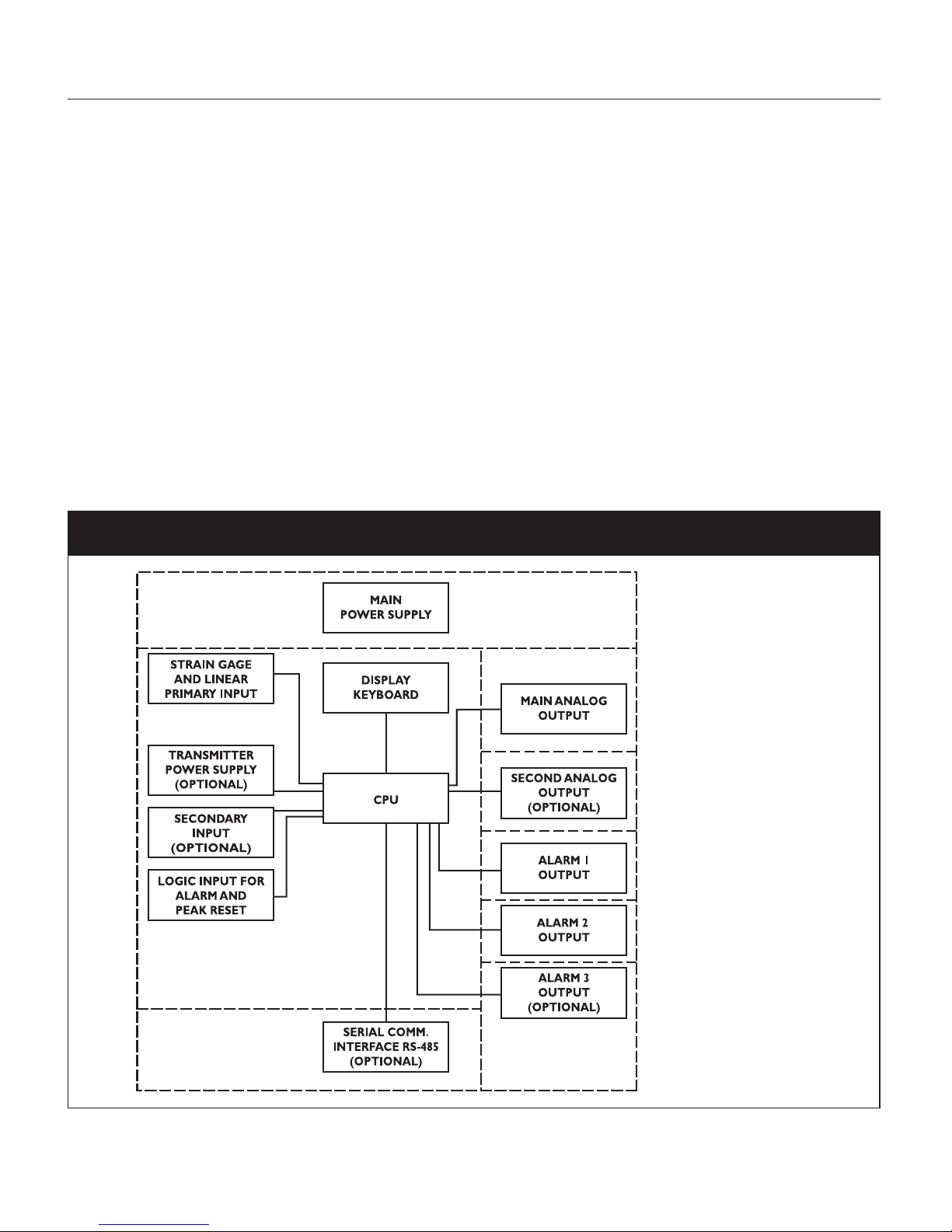
Fig. 1 Block Diagram of Electronics Layout
NOTE: Dashed Line represents insulation boundary.
Page 14
14
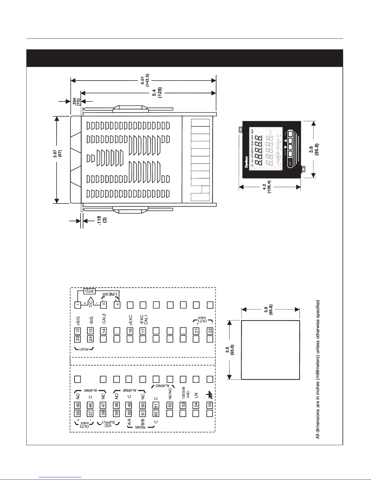
Fig. 2 Model UPR700 Outline Drawing
Page 15

UPR700 Microprocessor-Based Pressure/Process Indicator 15
3. UNPACKING
Upon receipt, examine package for shipping damage. Notify the carrier immediately in the event of
any evidence of damage, and retain shipping materials for their inspection.
This package should contain the instrument, two panel mounting brackets, a sheet of peel-off labels
with a variety of engineering units and an
Installation and Operation Manual
.
4. DIMENSIONAL INFORMATION
Dimensions: 3.78" X 3.78" X 6.01" overall (96mm X 96mm X 143.5mm)
Cutout: 3.62" X 3.62" (92mm X 92mm)
Depth behind panel: 5.04" (128mm)
Weight: 1.43 lbs. (650g)
5. HARDWARE
The UPR700 is shipped with the hardware jumpers set for the following:
Primary Input (Pressure) - Strain Gage
Optional Secondary Input - Thermocouple
Main Output - Voltage
Optional Secondary Output - Voltage
In addition the DIP switches controlling the software security lock codes are in the “OFF’ positions.
Please refer to the drawings in the appropriate sections to determine the correct jumper locations for
the input(s) and output(s) used in your particular application. It is necessary only to select the
category (e.g. Voltage or Current). The specific range will be chosen in the software menu.
Page 16

16
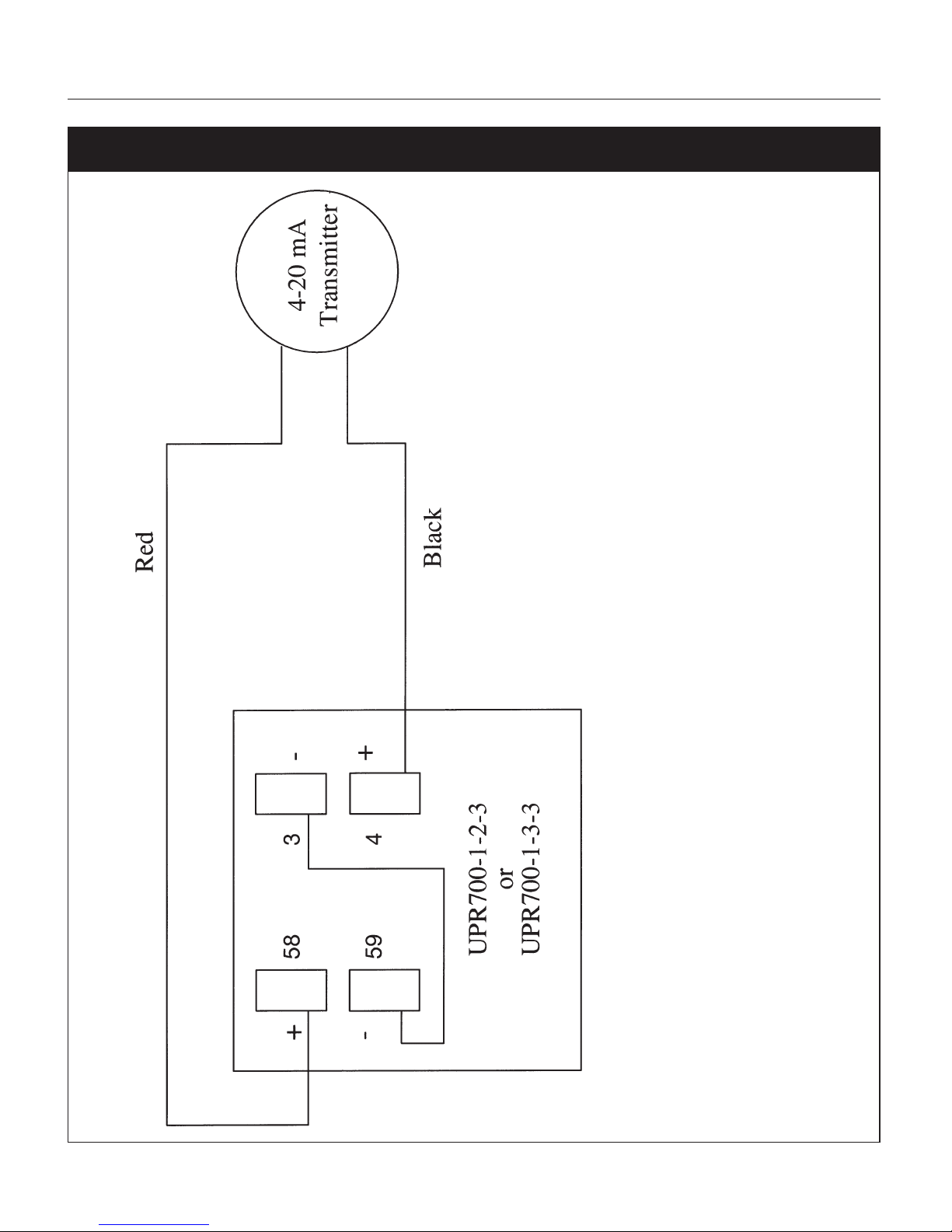
Fig. 3
UPR700 Wiring - 4-20mA Transmitter Internal 24 VDC Power Supply - Primary Input
Page 17
UPR700 Microprocessor-Based Pressure/Process Indicator 17
Fig. 4
UPR700 Wiring - 4-20mA Transmitter Internal 24 VDC Power Supply - Secondary Input
Page 18

18
6. MOUNTING AND WIRING
Please refer to Figure 2 for cutout dimensions and clearance requirements. Locate the two mounting
brackets packed with the instrument and have them available.
1. Remove instrument from case. To accomplish this, spread the two locking tabs located on either
side of the case. The instrument will move forward past the locked position. Grasp the bezel and
slide the instrument from the case. Depending on the options chosen, you may find that one or
two boards appear to be loosely mounted. This patent-pending design allows the instrument to
be removed from the case without having to overcome the friction of all terminals on all boards
at one time. Initially the CPU board and alarm board will be released, followed by the I/O and
digital communication boards.
2. Slide the instrument case into the cutout, being sure that it is right-side-up (terminal 1 at the
top). Attach the panel mounting hardware at diagonally opposite sides of the top and bottom of
the case, tightening the threaded rod until the case is secure against the panel.
3. Carefully slide the instrument back into its case, until the locking tabs have engaged. An audible
click will be heard as each tab engages.
4. Refer to the model number of the instrument to determine the hardware and options included as
part of your unit. Please refer to Section 6.1 for the terminal assignments. Terminals are accessed
by opening the terminal covers from the side with the “OPEN” legend.
NOTE 1:
The UPR700 is equipped with screw terminals, and no connectors are necessary when wiring the
unit
NOTE 2:
When wiring the alarms, wire to the Common and NO (normally open) terminals to maintain a failsafe configuration.
Fail-safe denotes a situation where the alarms relay coils are activated in a no-alarm situation. As the
relay coil is energized, terminals that are normally open are closed and can cause completion of a
circuit when used as an interlock. Should the alarm threshold be exceeded, OR should power be
lost to the instrument the contacts will open, and the circuit will be broken. If the alarm is a latching
alarm, it will require an external reset signal to be activated again.
If the alarm is used to provide a contact to an alarm device (light, horn buzzer, etc., when the
threshold is exceeded, wiring should be to the Common and NC (normally closed) terminals.
Activation of the relay coil will cause the contacts to open in a non-alarm situation, and to close if
the threshold is exceeded, or power is interrupted to the instrument. If the alarm is a latching alarm,
it will require an external reset signal to be activated again.
Page 19

UPR700 Microprocessor-Based Pressure/Process Indicator 19
NOTE 3: Relay Outputs
The contact rating of all outputs is equal to 2A/240 Vac on resistive load.
•To avoid electrical shock, connect power line at the end of the wiring procedure.
•For power connections use No 16 AWG or larger wires rated for at least 75°C.
• Use copper conductors only.
NOTE 4: Power Line
Before connecting the instrument to the power line, make sure that the line voltage corresponds to
the description on the identification label.
To avoid electrical shock, connect power line at the end of the wiring procedure. For supply
connections use No. 16 AWG or larger wires rated for at least 75°C.
• Use copper conductors only.
• Don’t run input wires together with power cables.
•For 24 V DC the polarity need not be observed.
The power supply input is fuse protected by a sub miniature fuse rated T, 1A, 250 V. When the fuse
is damaged, it is advisable to verify the power supply circuit It is necessary to send back the
instrument to Dynisco for service.
The safety requirements for Permanently Connected Equipment say:
•A switch or circuit-breaker shall be included In the building installation;
• It shall be in close proximity to the equipment and within easy reach of the operator
• It shall be marked as the disconnecting device for the equipment
NOTE 5:
A single switch or circuit breaker can drive more than one Instrument:
•When a neutral line is present, please connect it to terminal 54.
• Protective conductor terminals shall be connected to earth.
Page 20

20
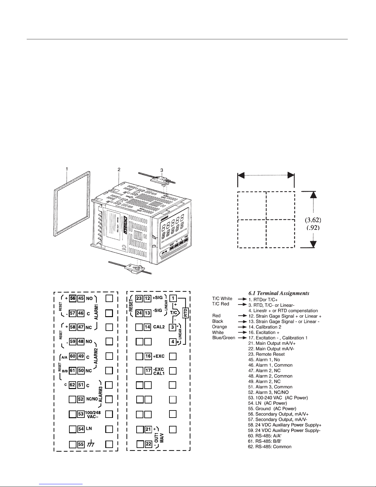
6.1 TERMINAL ASSIGNMENTS
1. RTD or T/C+
3. RTD, T/C- or Linear - Secondary Input (Optional)
4. Linear + or RTD compensation
12. Strain Gage Signal + or Linear +
13. Strain Gage Signal - or Linear -
14. Calibration 2 Primary Input
16. Excitation +
17. Excitation -, Calibration 1
21. Main Output mA/V +
22. Main Output mA/V -
23. Remote Reset
24. Remote Reset
45. Alarm 1. NO
46. Alarm 1, Common
47. Alarm 1. NC
48. Alarm 2, NO
49. Alarm 2. Common
50. Alarm 2, NC
51. Alarm 3, Common OPTIONAL
52. Alarm 3. NC/NO
53. 100-240 VAC OR 24 VAC OR 24 VDC (Polarity need not be observed)
54. LN LN 24 VDC
55. Protective Ground Protective Ground N/A
56. Secondary Output, mA/V +
OPTIONAL
57. Secondary Output. mA/V -
58. 24 VDC Auxiliary Power Supply +
OPTIONAL
59. 24 VDC Auxiliary Power Supply -
60. RS-485: A/A’
61. RS-485: B/B’ OPTIONAL
62. RS-485: Common
Page 21

UPR700 Microprocessor-Based Pressure/Process Indicator 21
6.2 µPR690 TO UPR700 WIRING CONVERSION TABLE
UPR700 Terminal µPR690 Terminal
Power
120 / 240 VAC 53 31
Line Neutral 54 32
Protective Ground 55 33
Transducer Dynisco Cable Color
Signal + Linear (+) 12 6 Red
Signal - Linear (-) 13 7 Black
Excitation (+) 16 8 White
Excitation (-) 17 9 Green
CAL 1 17 10 Blue
CAL 2 14 11 Orange
Alarms
A1 (N.O.) 45 24
A1 Common 46 25
A1 (N.C.) 47 26
A2 (N.O.) 48 27
A2 Common 49 28
A2 (N.C.) 50 29
Optional Alarm 3
A3 (N.O. / N.C.) 52 21
A3 Common 51 22
Analog Output
Voltage Out + 21 2
Voltage Out - 22 3
Current Out + 21 4
Current Out - 22 5
Optional 2nd Analog
mA/V Out (+) 56 N/A
MA/V Out (-) 57 N/A
OptIonal 24 VDC Transmitter Power Supply
24 VDC (+) 58 N/A
24 VDC (-) 59 N/A
External Reset Contacts
Reset 23 1
Reset Common 24 23
Optional Second Analog Input
Thermocouple Input
TC (+) 1 N/A
TC (-) 3 N/A
mA/V Input
lnput (+) 4 N/A
lnput (-) 3 N/A
RTD Input 3-wire
Red 1 N/A
Black 3 N/A
Black 4 N/A
Serial Communications (RS485 only)
A6016
B6117
COM 62 18
Page 22

22
7. START-UP PROCEDURE, UPR700 INDICATOR
In general, the UPR700 Pressure/Process Indicator is a microprocessor-based instrument, with the
capability of monitoring one or two process variables simultaneously. The primary input is
configured to accept a 350⍀ Strain Gage, but can be changed to accept high level voltage or
current. The primary input full-scale value can be as low as 10, and as high as 99,950 units. The
secondary input, if supplied, will accept a “J” type thermocouple, but can be changed to most
thermocouples or RTD’s, or to a high-level voltage or current. The secondary input full-scale value
can be as low as -1,000, and as high as 3,000 units.
The standard UPR700 has 2 SPDT dry contact closure alarms, with an optional third alarm. In
addition, it has one or two scalable analog retransmission outputs, or RS485 communications.
Alarm 1 is configured as a High Alarm at 40% of the full-scale transducer value, with 0.4 second
filtering, 1.0% hysteresis, Auto reset, failsafe mode, and it is linked to the primary input.
Alarm 2 is configured as a High Alarm at 60% of the full-scale value, with 0.4 second filtering, 1.0%
hysteresis, Auto reset, failsafe mode, and is also linked to the primary input,
Alarm 3, if supplied, is configured as a High Alarm at 80% of the full-scale value, with 0.4 second
filtering, 1.0% hysteresis, Auto reset, failsafe mode, and it is disabled (not linked to any input),
These terms will be described in the ALARMS section.
7.1 GETTING READY
1. Remove the instrument from its case. To accomplish this, spread the two locking tabs located on
either side of the case. The instrument will move forward past the locked position. Grasp the
bezel and slide the instrument from the case.
2. Slide the case into the panel cutout. MAKE SURE TERMINAL 1 IS AT THE TOP! Attach the panel
mounting hardware at diagonally opposite sides of the top and bottom of the case, tightening
the threaded rod until the case is secure against the panel.
3. Carefully slide the instrument into the case until the locking tabs engage with an audible click.
4. Attach the primary and secondary devices, (if supplied), and wire according to the terminal
assignments as described in the Dynisco INSTALLATION AND OPERATION MANUAL FOR
THE UPR700 MICROPROCESSOR-BASED PRESSURE/PROCESS INDICATOR (part number
974090) included with the instrument.
7.2 CONFIGURING THE UPR700
Apply power to the cabinet and allow the system to stabilize for about 30 minutes. The upper
Page 23

UPR700 Microprocessor-Based Pressure/Process Indicator 23
display will show a reading near zero, and the lower display will show the current temperature or
PEAK if the unit does not have secondary input. It may display OPEN if there is no transducer
connected, or if the transducer is amplified.
The keys on the UPR700 must be pressed and released to move about in the configure screens. Do
not press and hold a key unless told to do so; simply press the key and release it to advance to the
next screen. The arrow keys ( or ( may be held down to advance rapidly through the values.
7.3 KEYBOARD DESCRIPTION
The keyboard is composed of four push buttons, covered by a silicone protective operator, labeled
▼, ▲, FUNC and RESET.
The ▼ is called the “Down Arrow Key”, and is used to increment and decrement the parameter
value.
The ▲ is called the “Up Arrow Key”, and is used to increment and decrement the parameter value. It
also may be used to switch the lower display from the secondary input (if available) to the peak
value (if enabled) and back again. At power up, the lower display shows the secondary input value
(if present) or it shows the peak value. If there is no secondary input and the peak value is disabled,
the lower display is blank.
The FUNC (“function”) key is used to access the parameter to view and modify.
The RESET key is used to reset the stored peak value and to reset the alarms when held for 1
second, (once the alarm condition has cleared beyond the hysteresis value). This function is disabled
when the device is controlled by the serial link. In addition, when checking or changing parameters,
it is used to return to the normal display mode without storing the parameter change.
Pressing ▲ then RESET together, or ▼ then RESET together, may be used to jump to maximum or
minimum parameter values when the instrument is in function mode.
At power up, if the instrument detects a parameter error, the upper display shows
ERR #
, (where # is
the error number), and the lower display will show the parameter name. If the wrong parameter is a
run-time parameter (i.e.
AL 1
to
SO.TYP
) pressing the ▲ then ▼ together will cause the instrument
to load the default values for all parameters.
If the wrong parameter is a calibration or code parameter, pressing the FUNC then RESET keys
together, enables the instrument to access the run-time parameters. This function is intended only to
restore a misplaced parameter’s value; however, the performance of the instrument is not
guaranteed. The user is advised to check the stated parameter.
NOTE: All the actions explained above that require two or more pushbuttons, must follow the
pushbutton sequence exactly.
Page 24

24
7.4 OPERATING MODE DESCRIPTION
The FUNC key is used to access the parameters organized in five groups. Use the FUNC
pushbutton to access the Group 1 parameters; the last entry (showing
Group
and
None
is intended
to access the other groups of parameters, or pressing FUNC again returns to the normal display
mode. Each group has its own family of parameters, loosely grouped around the decreasing need to
change the parameters. Each group also has the ability to load its own default parameters and the
default values of the lower number groups.
8. CONFIGURATION
8.1 HARDWARE
The UPR700 is shipped with the hardware jumpers set for the following:
1. Main Input (Pressure) - Strain Gage
2. Secondary Input (Temperature) - Thermocouple*
3. Main Output - Voltage
4. Secondary Output - Voltage*
*If equipped with this option.
In addition, the DIP switches controlling the software security lock codes are in the “OFF” positions.
Please ensure that the correct jumper settings for the input(s) and output(s) used in your particular
application are selected. It is necessary only to select the category (e.g. Voltage or Current). The
specific range will be chosen in the software menu.
8.2 PARAMETERS
The UPR700 parameters are grouped in five sections guarded by three security levels. The more
common parameters are in the first groups, with the higher Group numbers for those parameters an
operator would not normally modify. Each group can be reset to its default value by two keystrokes.
This also resets the parameters of any lower numbered group to default. If GROUP 5 is set to default,
the entire instrument is reset to its default parameters. If a unit does not have a particular option, its
parameters will not appear. For example, an instrument that does not have RS-485 communications
will skip those parameters related to communications. Likewise, if a particular function is turned off,
its other parameters will not appear. For example, if Alarm 2 is turned to
OFF
in Group 3, the
hysteresis, reset, filter, type, and threshold functions will not appear on screen. Nor will the alarm
appear on he bar graph display.
Page 25

UPR700 Microprocessor-Based Pressure/Process Indicator 25
When the instrument is turned on, it will go through a self-test during which the front panel will
illuminate. The instrument will then be in the normal display mode showing the value of the main
input on the upper display, and the value of the secondary input on the lower display (if so
equipped). If there is no secondary input, the lower display will show the maximum peak value of
the main input. In the event that no input device is connected, both displays will show
OPEn
. If no
secondary input is present, the lower display will show
00000
indicating that the unit failed to full
scale, the bar graph display will be at 100% with the last segment flashing. Turn the power to the
instrument off and connect an input device to the appropriate terminals, and connect a
thermocouple or appropriate signal source to the secondary input terminals (if supplied). Upon
turning the instrument back on, the displays should have a numeric value, close to zero pressure on
the pressure display, and near room temperature on the thermocouple display. Depressing FUNC
will go automatically into the GROUP 1 parameters.
Successively pressing FUNC will scroll through all the parameters of GROUP 1. The last two
parameters of each group allow the default parameters to be restored, and returns to
GROUP
. If
nonE
is chosen in the group access function, the instrument will return to normal operating mode
after pressing of the FUNC key.
When in GROUP 1, if no keyboard activity is detected for approximately 10 seconds, the instrument
will automatically return to the normal display mode.
8.3 PARAMETER CONFIGURATION PROCEDURES
The parameters in the five groups are extensive, and not all parameters need to be addressed. While
they are fully explained in the following section, it would be well to review them prior to
configuring the instrument in your application. It is entirely possible that only a minimum number of
parameters need to be adjusted to have your process operating satisfactorily. Please note that at any
time, the default parameters may be reset to the factory settings. Each parameter group can be reset
at any time, (which also resets the levels with numbers higher than the selected group). To set a
default level, press the FUNC key until
DEFLT
shows on the lower display and
OFF
shows on the
upper display. Press the the ▼ or ▲ key until
ON 1
shows in the upper display. Press the FUNC key
to load all of the factory parameters for groups 1, 2, 3, 4, and 5.
To reset a specific group (and higher numbered groups) to the default factory settings, press the
FUNC key until
nonE
and
GROUP
show on the display. Press the ▲ key until the appropriate group
number appears in the upper display. Press the FUNC key to enter the appropriate group. Press the
FUNC key until
DEFLT
shows on the lower display and
OFF
shows on the upper display. Press the
▼ or ▲ key until
ON #
(where # is the Group number). Press the FUNC key to load the factory
parameters for that groups (and higher numbered groups).
8.3.1 SETTING THE LOGIC INPUT CONFIGURATION (IF SUPPLIED)
If the unit does not have the logic input option, skip to Section 8.3.3.
The Logic Input can be off, can be set to function as an alarm reset, a peak reset, perform remote
Page 26

26
zero calibration, or it can reset both alarm and peak and perform remote zero calibration. To verify
this parameter or to change it, press the FUNC key until
nonE
and
GROUP
show on the display.
Press the ▲ key until 4 shows in the upper display. Press the FUNC key until the lower display
shows LI.TYP. Press the ▼ or ▲ key until the upper display shows the correct selection: OFF, AL -
Alarms Reset, P - Peak Reset, AL-P - Alarm & Peak Reset, CAL.0 - Zero Calibration or ALL - All
Functions. Press the FUNC key to set the value and move to the next parameter, or press the RESET
key to go back to the active display.
8.3.2 SETTING THE LOGIC INPUT STATUS (IF SUPPLIED)
The Logic Input Status can be off, can be set to function as an alarm reset, a peak reset, or it can
reset both. To verify this parameter or to change it, press the FUNC key until
nonE
and
GROUP
show on the display. Press the ▲ key until
4
shows in the upper display. Press the FUNC key until
the lower display shows
LI.STS
. Press the ▼ or ▲ key until the upper display shows the correct
selection:
CLOSE
, or
OPEn
.
Press the FUNC key to set the value and move to the next parameter, or press the RESET key to go
back to the active display.
8.3.3 SETTING PEAK DETECTION
The Peak Detection can be either set to OFF, the default value of HIGH, or to LOW. To verify this
parameter or to change it, press the FUNC key until
nonE
and
GROUP
show on the display. Press
the ▲ key until
4
shows in the upper display. Press the FUNC key until the lower display shows
PEAK
. Press the ▼ or ▲ key until the upper display shows the correct value (
OFF, HI
, or LO). Press
the FUNC key to set the value and move to the next parameter, or press the RESET key to go back
to the active display.
8.3.4 SETTING THE LINE FREQUENCY
The Line Frequency default value is 60 Hz. To verify this parameter or to change to 50 Hz, press the
FUNC key until
nonE
and
GROUP
show on the display. Press the ▲ key until
4
shows in the upper
display. Press the FUNC key until the lower display shows
LINE.F
. Press the ▼ or ▲ key until the
upper display shows the correct frequency. Press the FUNC key to set the value. Press the FUNC
key to set the value and move to the next parameter, or press the RESET key to go back to the
active display.
8.3.5 SETTING THE DISPLAY FILTER
Filtering is an electrical method of averaging the displayed values over a period of time to arrive at a
more legible display. Filtering helps to eliminate short duration transients and spikes that may cause
false or spurious readings.
To change or view the Main Analog Output Filter, press the FUNC key until
nonE
and
GROUP
show on the display. Press the ▲ key until
2
shows in the upper display. Press the FUNC key until
Page 27

UPR700 Microprocessor-Based Pressure/Process Indicator 27
the lower display changes to
DSP.FL
. Using the ▼ or ▲ keys, select the amount of filtering desired,
from none
(OFF)
to five seconds. When finished, press the FUNC key to lock in the value and
advance to the next parameter.
NOTE: The parameter group legends of instruments manufactured prior to January 1998 refer to the
primary input as “Pressure”, and the secondary input as “Temperature” regardless of the
actual process variable being indicated. When asked in the menu to “Link” an alarm to an
input. “Pressure” is always the main input (upper display), and “Temperature” is always the
secondary input (lower display).
Fig. 5 Parameter Table
Group # Function Mnemonic Choices Default Value
Group 5 Primary Input Selection PI.TYP Str, 0-20, 4-20, 0-5, 0-10 Str
Group 5 Secondary Input Selection SI.TYP OFF, tc, rtd, 0-20, 4-20, 0-10 Tc
Group 4 Shunt Calibration SHUNT OFF,On On
Group 4 Shunt Value SHNT% 40.0 TO 100.0% 80.0%
Group 3 Input Full Scale Value PI.FSV 10 TO 99.950 10000
Group 3 Input Low Scale Value PI.LSV ± 25% OF SFV OF FS V 0
Group 3 Input Decimal Point Position PI.DP None, 1,2,3,4 places None
Group 3 Secondary Input T/C Type Sl.TC tc J, tc CA, tc L, tc n tc J
Group 3 Alarm I Input Channel Link AI.LNK OFF, Prl.ln, Sec.ln Prl.ln
Group 3 Alarm I Type AI.TYP HI, LO, lnhib HI
Group 3 Alarm 2 Input Channel Link A2.LNK OFF, Prl.ln, Sec.ln PrLIn
Group 3 Alarm 2 Type ALTYP HI, 10, lnhib HI
Group 2 Zero Calibration ZERO.C OFF, On, CLEAr OFF
Group 2 Span Calibration SPAN.C OFF, On, CLEAr OFF
Group 1 Alarm I Threshold AL1 TO 110%of span 40% of range
of related input
Group 1 Alarm 2 Threshold AL2 TO 110% of span 60% of range
of related input
In this example, these are functions necessary to allow operation of a pressure/temperature indicator
with two high alarms.
8.4 PRIMARY INPUT SETUP
8.4.1 SETTING THE PRIMARY INPUT T YPE FOR A STRAIN GAGE T RANSDUCER
If using a
Dynisco
transducer, the model number of the transducer will designate its own electrical
output. For example, in plastic melt applications, the PT462E-5M-6/18 or TPT432A-10M-6/18 have
a strain gage (0-3.33 mV/V dc full scale) signal output. Amplified units have a number where the
strain gage units have a letter (E or A). The PT4624-5M-6/18 has a 4-20 mA signal output; the
PT4625-5M-6/18 has a 0-5 Vdc signal output, while PT4626-5M-6/18 has a 0-10 Vdc signal output.
Page 28

28
In Industrial applications, amplified units have a middle or end number of 4, 5, or 6. The S840-0001C has a 4-20 mA signal output; the PT150-7.5M has a 0-5 Vdc signal output, while PT276-5M has
a 0-10 Vdc signal output.
If you have an amplified transducer, or other amplified input, skip to Section 8.4.2.
The UPR700’s default setting is strain gage input. To verify that the input is set for strain gage, press
the FUNC key until
nonE
and
GROUP
show on the display. Press the ▲ key until
5
shows in the
upper display. Press the FUNC key and the upper display should show
Str
while the lower display
shows
PI.TYP
. If not, press the ▼ or ▲ key until the upper display changes to
Str
(for strain gage).
Press the FUNC key to set the value. The upper display changes to tc with
SI.TYP
on the lower
display. Press the RESET key to return to the active display.
Remember to change the jumper settings to correspond to the proper input as shown in Figure 6 for
board location and Figure 7 for amplified input jumpers.
Fig. 6 UPR700 Board Location
Page 29

UPR700 Microprocessor-Based Pressure/Process Indicator 29
Fig. 7 Input/Output Jumper Location
8.4.2 SETTING THE SHUNT CALIBRATION FOR STRAIN GAGE TRANSDUCERS
AND
AMPLIFIED UNITS
The Dynisco strain gage transducers and amplified transmitters (if so equipped) have an internal
shunt to allow the UPR700 to set the span full scale value automatically. To Access the Shunt
Calibration parameter, press the FUNC key until
nonE
and
GROUP
show on the display. Press the
▲ key until
4
shows in the upper display. Press the FUNC key and the upper display will show
OFF
while the lower display shows
SHUNT
. Press the ▼ or ▲ key until the upper display changes to the
ON
. Press the FUNC key to set the value and move to the next Shunt parameter.
The upper display will show
80.0
while the lower display shows
SHNT%
. In most cases, the
Dynisco transducers have an 80% shunt value so no changes need be made. However, some
transducers and strain gages have shunt values that may range from 40-100%. If so, press the ▼ or
▲ key until the upper display changes to the correct values. Press the FUNC key to set the value.
Press the RESET key to go back to the active display.
Page 30

30
8.4.3 SETTING THE PRIMARY INPUT TYPE FOR AN AMPLIFIED T RANSMITTER
If using a voltage or current output transducer, the model number of the transducer will designate its
own electrical output. For example, a PT4624-7.5M-6/18 or an S840-000-10M has an amplified
signal output. In plastic melt applications, amplified units have a number where the strain gage units
have a letter (E or A). The PT4624-7.5M-6/18 has a 4-20 mA signal output; the PT4625-7.5M-6/18
has a 0-5 Vdc signal output, while PT4626-7.5M-6/18 has a 0-10 Vdc signal output. In Industrial
applications, amplified units have a middle or end number of 4, 5, or 6. The S840-000-1C has a 420 mA signal output; the PT150-7.5M has a 0-5 Vdc signal output, while PT276-5M has a 0-10 Vdc
signal output.
If you have a strain gauge transducer, load cell, or other mV/V device, see Section 8.4.1.
The Instrument’s default setting is strain gage input. To select another input for a transmitter or to use
another process instrument, such as humidity sensors, position sensors, etc., press the FUNC key until
nonE
and
GROUP
show on the display. Press the ▲ key until
5
shows in the upper display. Press the
FUNC key and the upper display will show
Str
while the lower display shows
PI.TYP
. Press the ▼ or ▲
key until the upper display changes to the correct value (
0-20
for 0-20 mA linear input,
4-20
for 4-20
mA current loop input,
0-5
for 0-5 Vdc linear input, and
0-10
for 0-10 Vdc linear input. Press the FUNC
key to set the value. Press the RESET key to go back to the active display.
Remember to change the jumper settings to correspond to the proper input as shown in Figure 6 for
board location and Figure 8 for amplified input jumpers.
Fig. 8 Input Selection J84 for Amplified Input
Page 31

UPR700 Microprocessor-Based Pressure/Process Indicator 31
8.4.4 SETTING THE PRIMARY INPUT FULL-SCALE V ALUE
The model number of the transducer or transmitter will designate the full-scale pressure capability.
For example, model number TPT432A-5M-6/18 indicates that the full-scale pressure is 5,000 (5M),
while the PT150-5C indicates that the full-scale pressure is 500 (5C). Since the default value in the
instrument is 10,000 full scale, the input full-scale value must be changed to 5,000 (or 500). Note
that there are no units here, it can be psi, bar, mPa, kg/cm2 or any engineering unit; the magnitude
is all that is important. To set the full-scale value, press the FUNC key until
nonE
and
GROUP
show
on the display. Press the ▲ key until
3
shows in the upper display. Press the FUNC key and the
upper display will show 10000 while the lower display shows
PI.FSV
. Hold the ▼ or ▲ key until the
upper display changes to 5000 (or whatever the full-scale value of the primary input may be). Press
the FUNC key to set the value. Check that the next display reads 0 in the upper display and
PI.LSV
in the lower display; if not, set to zero with the arrow keys and press FUNC to lock in the value.
Finally, press the RESET key to go back to the active display. Similarly, if the full-scale pressure is
350 Bar (3.5CB), set
PI.FSV
to 350.
8.4.5 SETTING THE PRIMARY INPUT LOW-SCALE V ALUE
For applications where a low scale value is non-zero, the Instrument can provide a low scale value
of ±25% of the full scale value.
To set the low-scale value, press the FUNC key until
nonE
and
GROUP
show on the display. Press
the ▲ key until
3
shows in the upper display. Press the FUNC key and the upper display will show a
value while the lower display shows
PI.SFV
. Press the FUNC key and the upper display will show 0
while the lower display shows
PI.LFV
. Hold the ▼ or ▲ key until the upper display changes to
whatever the low-scale value of the primary input may be. Press the FUNC key to set the value.
Finally, press the RESET key to go back to the active display.
8.4.6 SETTING THE PRIMARY INPUT DECIMAL PLACE
To set the decimal place, press the FUNC key until
nonE
and
GROUP
show on the display. Press the
▲ key until
3
shows in the upper display. Press the FUNC key until the lower display shows PI.DP.
Press the ▼ or ▲ key until the upper display shows the correct decimal place location. Press the
FUNC key to set the value. Finally, press the RESET key to go back to the active display.
8.4.7 SETTING THE PRIMARY INPUT FAILSAFE MODE
The Primary Input Failsafe Mode is nothing more than a safety mechanism that tells the instrument
what to do in the event of a loss of the primary signal. If the system is set up to shut down the
process in a high alarm condition, the Primary Input Failsafe parameter sets the value of the primary
input to full scale if it looses the primary signal. If the system is set up to shut down the process in a
low alarm condition, the Primary Input Failsafe parameter sets the value of the primary input to low
scale if it looses the primary signal. The default Primary Input Failsafe Mode is to set the value to full
scale high.
Page 32

32
To set the Primary Input Failsafe Mode, press the FUNC key until
nonE
and
GROUP
show on the
display. Press the ▲ key until
4
shows in the upper display. Press the FUNC key until the lower
display shows
PI.IFS
. Press the ▼ or ▲ key until the upper display shows the correct mode, either
HI
or Lo. Press the FUNC key to set the value. Finally, press the RESET key to go back to the active
display.
8.5 SECONDARY INPUT SETUP
Skip this section if there is no secondary input or if this is a new installation and the secondary input
is for a “J” type thermocouple expressed in degrees Fahrenheit (°F).
8.5.1 SETTING THE SECONDARY INPUT TYPE
The Secondary Input measured values will show in the lower display. The Instrument’s default
secondary input setting is for a “J” type thermocouple. To select another type of input, press the
FUNC key until
nonE
and
GROUP
show on the display. Press the ▲ key until
5
shows in the upper
display. Press the FUNC key twice and the upper display will show tr while the lower display shows
SI.TYP
. Press the ▼ or ▲ key until the upper display changes to the correct value (
rtd
for Platinum
RTD,
0-20
for 0-20 mA linear input,
4-20
for 4-20 mA current loop input,
0-10
for 0-10 Vdc linear
input, and
OFF
if the input is to be disabled. Press the FUNC key to set the value. Finally, press the
RESET key to go back to the active display.
Remember to change the jumper settings to correspond to the proper input as shown in Figure 9 for
board location and Figure 10 for input jumpers.
Fig. 9 UPR700 Board Location
Page 33

UPR700 Microprocessor-Based Pressure/Process Indicator 33
Fig. 10 Secondary Input Jumper Location
Page 34

34
8.5.2 SETTING THE SECONDARY INPUT SCALE AND DECIMAL POINT
Skip to section 8.5.3 if the secondary input is for an RTD or a thermocouple.
If the Instrument’s secondary input is set as a voltage or current, the Range Values need to be set.
Press the FUNC key until
nonE
and
GROUP
show on the display. Press the ▲ key until
3
shows in
the upper display. Press the FUNC key and the upper display will show the full scale value while
the lower display shows
SI.FSV
. Press the FUNC key until the lower display changes to
SI.LO
. Using
the ▼ or ▲ keys, enter the zero value for the input. For example if the input from a device is 500-
3,000 units, it is 500 units at zero, so enter 500. Press the FUNC key to set the value. The lower
display will change to
SI.HI
. Using the ▼ or ▲ keys, enter the high (full-scale) value for the input.
For example if the input from a device is 500-3,000 units, it is 3,000 units at full scale, so enter
3000. Press the FUNC key to set the value. The lower display will change to
SI.DP
, the decimal
point position for the secondary input. Using the ▼ or ▲ keys, select the position for the decimal
point for this input and press FUNC to lock in the value. Finally, press the RESET key to go back to
the active display.
8.5.3 SETTING THE T HERMOCOUPLE TYPE AND UNITS
If the secondary input is from a thermocouple, set the thermocouple type and temperature units, by
pressing the FUNC key until
nonE
and
GROUP
show on the display. Press the ▲ key until
3
shows
in the upper display. Press the FUNC key until the lower display shows
SI.TC
. Press the ▼ or ▲ key
until the upper display changes to the correct value (
tc j
for type “J”,
tc CA
for type “K”,
tc L
for type
“L”, and
tc n
for a type “N” thermocouple). Press the FUNC key to set the value. The upper display
changes to
FAHr
(for Fahrenheit) while the lower display shows
SI.C/F
. Press the ▼ or ▲ key to
change to Celsius
CEL
or if desired.
These inputs are factory pre-calibrated for the following ranges, and require no further calibration.
Thermocouple: Type J -200 - 800°C -328 - 1472°F
Type K (CA) -200 - 1200°C -328 - 2192°F
Type L -200 - 800°C -328 - 1472°F
Type N 0 - 1300°C 32 - 2372°F
RTD Pt100 -200 - 600°C -328 - 1112°F
8.5.4 SETTING THE SECONDARY INPUT FAILSAFE MODE
The Secondary Input Failsafe Mode is a safety mechanism that tells the instrument what to do in the
event of a loss of the Secondary signal. In the event of a Secondary input signal loss, the Secondary
Input Failsafe parameter sets the value of the primary input to full scale (in the default mode).
To set the Primary Input Failsafe Mode, press the FUNC key until
nonE
and
GROUP
show on the
display. Press the ▲ key until
4
shows in the upper display. Press the FUNC key until the lower
display shows
SI.IFS
. Press the ▼ or ▲ key until the upper display shows the correct mode, either
HI
or Lo. Press the FUNC key to set the value. Finally, press the RESET key to go back to the active
Page 35

UPR700 Microprocessor-Based Pressure/Process Indicator 35
display.
8.6 SETTING THE ALARMS
All Alarms supplied with the Instrument can be linked to either the Primary Input or the Secondary
Input (if available), and are capable of being set as High Level Alarms or Low Level Alarms, and may
operate in either Failsafe or Direct condition.
Failsafe means that in the event of power failure to the Instrument, the Alarm will activate. Use this
feature on a shutdown alarm. Please note that in a proper operating condition in Failsafe mode, the
Normally Closed Contact are held OPEN, while the Normally Open contacts are held CLOSED. On
power failure, they are released.
On start-up, a Low Alarm may cause the unit to go into an undesired alarm condition prior to
reaching running conditions. This Alarm can be masked so that the Low Alarm will be deactivated
until it has gone above the alarm value for the first time. It will then operate as a normal low alarm.
The default values for Alarm 1 are: high alarm at 40% of full scale, linked to the primary input, 0.4
second filtering, 1% hysteresis, automatic reset, and failsafe mode. Each alarm may be set to 110%
of full scale.
The default values for Alarm 2 are: high alarm at 60% of full scale, linked to the primary input, 0.4
second filtering, 1% hysteresis, automatic reset, and failsafe mode.
The default values for Alarm 3, if supplied, are: high alarm at 80% of full scale, disabled (not linked
to any input), 0.4 second filtering, 1% hysteresis, automatic reset, and failsafe mode.
Set the Alarm parameters before setting the alarm value. If the alarm parameters have already been
set, set the alarm values as described in section 8.6.7.
8.6.1 SETTING WHICH CHANNEL ALARM WILL MONITOR
(ALARM INPUT CHANNEL LINK)
The Alarm 1 Input Channel Link defaults to the primary input. To check or change this value press
the FUNC key until
nonE
and
GROUP
show on the display. Press the ▲ key until
3
shows in the
upper display. Press the FUNC key until
A1.LNK
shows in the lower display. Select the choice
desired by pressing the ▼ or ▲ keys. The choices are:
OFF
, (disabled), linked to the primary input
Prl.In
, or linked to the secondary input
Sec.In
. Note: if you do not have a secondary input,
Sec.In
will not appear as a choice. Press the FUNC key to lock in the value and advance to the next
parameter. Similarly, you may configure Alarm 2
(A2.LNK)
and if supplied, Alarm 3
(A3.LNK)
.
8.6.2 SETTING ALARM TYPE
A high alarm will activate when a set point is exceeded. A low alarm will activate whenever the
value falls below a set point (including startup). An inhibited low alarm must exceed the low alarm
Page 36

36
set point before it is enabled. Then it will work like a low alarm. This is ideal on startup.
The default alarm type for Alarm 1 is high. To check or change this value press the FUNC key until
nonE
and
GROUP
show on the display. Press the ▲ key until
3
shows in the upper display. Press the
FUNC key until
A1.TYP
shows in the lower display. Using the ▼ or ▲ keys, select
HI
for high level
alarm, LO for low level alarm or
Inhib
for a low level alarm with mask at start-up. Press the FUNC
key to lock in the value and advance to the next parameter. If finished, press RESET to return to the
operating screen. Similarly, you may configure Alarm 2
(A2.TYP)
and if supplied, Alarm 3
(A3.TYP)
.
8.6.3 SETTING THE FILTERING FOR ALARM 1
Filtering is an electrical method of averaging the input values over a period of time to arrive at a
smoother curve. This helps to eliminate short duration transients and spikes which can cause alarms,
but which may cause false or spurious readings.
The Alarm filter default is 0.4 seconds of filtering. To change this value, press the FUNC key until
nonE
and
GROUP
show on the display. Press the ▲ key until
2
shows in the upper display. Press the
FUNC key until the lower display changes to
A1.FL
. Using the ▼ or ▲ keys, select the amount of
filtering desired, from none
(OFF)
to five seconds. When finished, press the FUNC key to lock in the
value and advance to the next parameter. If finished, press RESET to return to the operating screen.
Similarly, you may configure Alarm 2
(A2.FL)
and if supplied, Alarm 3
(A3.FL)
.
8.6.4 SETTING THE HYSTERESIS FOR ALARM
Hysteresis is used to describe the amount that the reading must drop below the alarm point (in a
high alarm) or must rise above the alarm point (in a low alarm) to clear the alarm condition. This
helps to eliminate short duration alarms when operating near the alarm condition. To change or
view this value, press the FUNC key until
nonE
and
GROUP
show on the display. Press the ▲ key
until 4 shows in the upper display. Press the FUNC key until the lower display changes to
A1.HYS
.
The values for hysteresis can range from .1% to 10.0%. Press the ▼ or ▲ keys until the upper
display changes to the desired value. Press the FUNC key to lock in the value and advance to the
next parameter, or press RESET to return to the operating screen. Similarly, you may configure
Alarm 2
(A2.HYS)
and if supplied, Alarm 3
(A3.HYS)
.
8.6.5 SETTING THE RESET MODE FOR ALARMS
The Alarm Reset Mode determines if the alarm resets itself once the alarm condition is been
corrected, or whether the operator must press a button to reset the alarm. The Alarm Reset Mode
default is automatic reset once the alarm has cleared. To change or view this value, press the FUNC
key until
nonE
and
GROUP
show on the display. Press the ▲ key until
4
shows in the upper display.
Press the FUNC key until the lower display changes to
A1.RES
. The values for reset mode is either
Auto
for automatic reset, or
LAtCH
for manual reset. Press the ▼ or ▲ keys until the upper display
changes to the desired value. Press the FUNC key to lock in the value and advance to the next
parameter, or press RESET to return to the operating screen. Similarly, you may configure Alarm 2
(A2.RES)
and if supplied, Alarm 3
(A3.RES)
.
Page 37

UPR700 Microprocessor-Based Pressure/Process Indicator 37
8.6.6 SETTING THE FAILSAFE MODE FOR ALARMS
The Alarm Failsafe Mode determines how the alarms react in the event of a power failure to the
UPR700. In the failsafe mode, the alarms will activate in the event of power loss. In non-failsafe
mode they cannot activate in the event of power loss. The Alarm failsafe mode default is failsafe
mode. To change or view this value, press the FUNC key until
nonE
and
GROUP
show on the
display. Press the ▲ key until
4
shows in the upper display. Press the FUNC key until the lower
display changes to
A1.FSM
. The options for failsafe mode are either FS for failsafe mode, or
nFS
for
non-failsafe mode. Press the ▼ or ▲ keys until the upper display changes to the desired value. Press
the FUNC key to lock in the value and advance to the next parameter, or press RESET to return to
the operating screen. Similarly, you may configure Alarm 2
(A2.FSM)
and if supplied, Alarm 3
(A3.FSM)
.
Please note that the wiring must be considered: For failsafe operation the alarm contacts must be
wired differently to have operation as expected. This is because the UPR700 holds the contact relay
in an energized state during normal operation. In the event of an alarm condition or the loss of
power to the UPR700, the relay will be de-energized and will then open. The same holds true for a
NC contact. It will be held OPEN during normal operation. In the event of an alarm condition or the
loss of power to the UPR700, the relay will be de-energized and will then close.
8.6.7 SETTING THE ALARMS VALUE (ALARMS THRESHOLD)
The Alarm 1Threshold Values, is the value beyond which the Alarm will activate (i.e. the threshold).
Alarm 1 is set in the same engineering units that the Full Scale Value uses. To change or view this
value when in the operating screen, press the FUNC key, when in the main screen, and the lower
display will change to
AL1
with the threshold value in the upper display. Press the ▼ or ▲ keys until
the upper display changes to the desired value. Press the FUNC key to lock in the value and
advance to the next parameter, or press RESET to return to the operating screen. Similarly, you may
configure Alarm 2
(AL2)
and if supplied, Alarm 3
(AL3)
.
8.6.8 SETTING THE ALARMS MASK RESET TYPE
The Alarm 1 Mask Reset may only be used on alarms configured as inhibited Low Alarms on startup.
It prevents the alarm from activating (masks the alarm) until the value of the primary input exceeds
the alarm value. To change or view this value when in the operating screen, press the FUNC key
until the lower display changes to
AL.MSK
with
OFF
in the upper display. Press the ▼ or ▲ keys
until the upper display changes to
rESEt
. Press the FUNC key to lock in the value and advance to
the next parameter, or press RESET to return to the op screen. You may similarly configure Alarm 2
and if supplied, Alarm 3.
8.7 MAIN AND SECONDARY ANALOG OUTPUT (RETRANSMISSION) SETUP
This set of parameters will only be available for units that include an active secondary input (
SI.TYP
other than
OFF
); otherwise it defaults to the primary input.
Page 38

38
8.7.1 SETTING THE MAIN ANALOG OUTPUT T YPE
The Main Analog Output Type sets the output to specific voltages or currents. The available outputs
are 0-20 mA, 4-20 mA, 0-10 VDC, -10 to +10 VDC, and 0-5 VDC. To change or view this value,
press the FUNC key until
nonE
and
GROUP
show on the display. Press the ▲ key until
5
shows in
the upper display. Press the FUNC key until the lower display changes to
MO.TYP
, and the upper
display shows the selected type. Press the ▼ or ▲ keys until the upper display changes to the
desired value. Then press the FUNC key to lock in the value and advance to the next parameter, or
press RESET to return to the operating screen. Similarly if the unit has a Secondary input, the
Secondary Analog Output Type
(SO.TYP)
can be set in the same manner.
Remember to change the jumper settings to correspond to the proper output as shown in Fig. 9 for
board location and Fig. 11 for Main Analog output jumpers and Fig. 12 for Second Analog output
jumpers.
8.7.2 SETTING THE MAIN ANALOG OUTPUT LINK
To change or view this value, press the FUNC key until
nonE
and
GROUP
show on the display.
Press the ▲ key until
3
shows in the upper display. Press the FUNC key until the lower display
changes to
MO.LNK
, and the upper display shows the selected type, either
PrI.In
(the primary input)
or
SEc.In
(the secondary Input). Press the ▼ or ▲ keys until the upper display changes to the desired
value. Then press the FUNC key to lock in the value and advance to the next parameter, or press
RESET to return to the operating screen. . Similarly the Secondary Analog Output Link
(SO.LNK)
can be set in the same manner.
8.7.3 SETTING THE MAIN ANALOG OUTPUT RANGE LOW
To change or view the Main Analog Output Range Low, press the FUNC key until
nonE
and
GROUP
show on the display. Press the ▲ key until
3
shows in the upper display. Press the FUNC
key until the lower display changes to
MO.LO
. Press the ▼ or ▲ keys until the upper display
changes to the desired value. The value may be anything from 0 to the primary input full scale value,
PI.FSV
if the
MO.LNK
is set to
PrL.Ln
, or if the
MO.LNK
is set to
SEc.Ln
, the value may be from 1000 to 3000. Once the desired value is set, press the FUNC key to lock in the value and advance
to the next parameter, or press RESET to return to the operating screen. Similarly the Secondary
Analog Output Range Low
(SO.LO)
can be set in the same manner.
8.7.4 SETTING THE MAIN ANALOG OUTPUT RANGE HIGH
To change or view the Main Analog Output Range High, press the FUNC key until
nonE
and
GROUP
show on the display. Press the ▲ key until
3
shows in the upper display. Press the FUNC
key until the lower display changes to
MO.HI
. Press the ▼ or ▲ keys until the upper display
changes to the desired value. The value may be anything from 0 to the primary input full scale value,
PI.FSV
if the
MO.LNK
is set to
PrL.Ln
, or if the
MO.LNK
is set to
SEc.Ln
, the value may be from 1000 to 3000. Once the desired value is set, press the FUNC key to lock in the value and advance
to the next parameter, or press RESET to return to the operating screen. Similarly the Secondary
Analog Output Range High
(SO.HI)
can be set in the same manner.
Page 39

UPR700 Microprocessor-Based Pressure/Process Indicator 39
Fig. 11 Main Analog Output Jumper Location
Fig. 12 Secondary Analog Output Jumper Location (optional)
Page 40

40
8.7.5 SETTING THE MAIN ANALOG OUTPUT FILTER
Filtering is an electrical method of averaging the output values over a period of time to arrive at a
smoother curve. This helps to eliminate short duration transients and spikes that may cause false or
spurious readings.
To change or view the Main Analog Output Filter, press the FUNC key until
nonE
and
GROUP
show on the display. Press the ▲ key until
2
shows in the upper display. Press the FUNC key until
the lower display changes to
MO.FL
. Using the ▼ or ▲ keys, select the amount of filtering desired,
from none
(OFF)
to five seconds. When finished, press the FUNC key to lock in the value and
advance to the next parameter. Similarly the Secondary Analog Output Filter
(SO.FL)
can be set in
the same manner.
8.8 SETTING THE SECURITY CODES
The security code setting is accessible by setting an internal dip switch (see Figure 13 below). There
are three Security levels. When each level has been assigned a code access to the parameters will be
available as follows:
• Level A: Allows access to parameters in Group 1 Only
• Level B: Allows access to parameters in Groups 1 and 2 Only
• Level C: Allows access to parameters to all Groups 1 - 5
To enter the security mode, remove the instrument form its case and reconfigure the internal dipswitch settings to the Security Mode by placing SW1 and SW2 in the ON position.
Fig. 13 CPU Board DIP Switch Locations
Page 41

UPR700 Microprocessor-Based Pressure/Process Indicator 41
When the instrument is re-inserted into its case, the upper display will show
CodE
and the lower
display will show
UPR
.
8.8.1 SETTING THE SECURITY CODES FOR LEVEL A
To view or change the security code, press the FUNC key and the lower display changes to
CODE.A
. The upper display shows 0, which indicates no security, and 1 means all parameters
related to levels A, B, and C are always locked). Press the ▼ or ▲ keys until the desired security
code number (from 2 to 250) appears in the upper display. Press the FUNC key to lock in the value.
The upper display changes to 1, and the lower display changes to
CODE.B
. This means that ONLY
Levels B and C are locked, NOT Level A. If finished remove the instrument from its case and place
both dip switch SW1 and SW2 into the OFF position to return to the operating mode; otherwise,
continue with the next step.
8.8.2 SETTING THE SECURITY CODES FOR LEVEL B
If you first set
CODE.A
, the lower display will read
CODE.B
; if not, press the FUNC key to move to
CODE.B
. The upper display shows 0, which indicates no security; or it may show 1, which means all
parameters related to levels A, B, and C are always locked). Press the ▼ or ▲ keys until the desired
security code number (from 251 to 500) appears in the upper display. Press the FUNC key to lock in
the value. The lower display changes to
CODE.C
, and the Upper display shows 1. This means that all
levels are locked and cannot be changed. If finished, remove the instrument from its case and place
both dip switch SW1 and SW2 into the OFF position to return to the operating mode.
8.8.3 SETTING THE SECURITY CODES FOR LEVEL C
If you first set
CODE.A
and
CODE.B
, the lower display will read
CODE.C
. If not, press the FUNC
key to move to
CODE.C
. The upper display shows 0, which indicates no security; a 1 means all
parameters related to levels A, B, and C are always locked). Press the ▼ or ▲ keys until the desired
security code number (from 501 to 1000) appears in the upper display. Press the FUNC key to lock
in the value. The upper display changes to CodE and the lower display changes to
UPR
. If finished,
remove the instrument from its case and place both dip switch SW1 and SW2 into the OFF position
to return to the operating mode.
Once the security codes are selected, they CANNOT be displayed. If the codes are forgotten, new
values must be entered using the above procedure. It is recommended that a code be set for each
security level. Note that unlocking the Level C code unlocks Levels A, B, and C. To, relock a code,
simply enter any incorrect number and all the locked levels will relock. Unlocking the Level B code,
unlocks Levels A and B. Unlocking Level A unlocks only Level A. When the
SECUR
functions are
accessed in Group 1, the levels that are locked will be followed by a decimal point.
Page 42

42
9. OPERATION
9.1 PRIMARY INPUT CALIBRATION
NOTE: In this section the word
Calibration
means to match the Instrument to the input device, so
that a specific signal from the input device is equated to a specific pressure and no other, (to
the capabilities of its input resolution).
Apply power to the cabinet and allow the system to stabilize for about 30 minutes. Allow the
transducer or other input device to come up to operating conditions.
9.1.1 CALIBRATION OF PRESSURE T RANSDUCERS EQUIPPED WITH
AN
INTERNAL SHUNT RESISTOR
Be sure that the full scale and low scale values (
PI.FSV
and
PI.LSV
) have been set to match the range
of the transducer and that the
SHUNT
function is ON and set to the correct percentage (80% for a
typical Dynisco transducer).
To calibrate the transducer to the instrument, press the FUNC key until
nonE
and
GROUP
show on
the display. Press the ▲ key until
2
shows in the upper display. Press the FUNC key and the lower
display changes to
ZERO.C
. The upper display shows
OFF
. Press the ▼ or ▲ keys until the upper
display changes to ON. Press the FUNC key to calibrate the zero value. The lower display changes
to
SPAN.C
. The upper display shows
OFF
. Press the ▼ or ▲ keys until the upper display changes to
ON
.
Press the FUNC key to calibrate the span value. When the legend
DSP.FL
appears in the lower
display, calibration is complete. Press RESET to return to the operating screen.
9.1.2 CALIBRATION OF AMPLIFIED PRESSURE TRANSMITTERS EQUIPPED WITH
AN
INTERNAL SHUNT RESISTOR
Be sure that the full scale and low scale values (
PI.FSV
and
PI.LSV
) have been set to match the range
of the transducer and that the
SHUNT
function is turned
OFF
.
To calibrate the transducer to the instrument, press the FUNC key until
nonE
and
GROUP
show on
the display. Press the ▲ key until
2
shows in the upper display. Press the FUNC key and the lower
display changes to
ZERO.C
. The upper display shows
OFF
. Press the ▼ or ▲ keys until the upper
display changes to ON. Press the FUNC key to calibrate the zero value. The lower display changes
to
SPAN.C
. The upper display shows
OFF
. Press the ▼ or ▲ keys until the upper display changes to
CLEAr. Press the FUNC key to calibrate the span value. When the legend
DSP.FL
appears in the
lower display, calibration is complete. Press RESET to return to the operating screen.
Page 43

UPR700 Microprocessor-Based Pressure/Process Indicator 43
9.1.3 CALIBRATION OF PRESSURE T RANSDUCERS EQUIPPED WITH
EXTERNAL SHUNT RESISTORS
Install the external shunt resistor across terminals 13 (signal -) and 14 (Cal 2). Be sure that the full
scale and low scale values (
PI.FSV
and
PI.LSV
) have been set to match the range of the transducer
and that the
SHUNT
function is
ON
and set to the correct percentage (as supplied by the transducer
manufacturer. If the values supplied is an actual pressure value, convert to a percentage and enter in
SHNT.%
).
To calibrate the transducer to the instrument, press the FUNC key until
nonE
and
GROUP
show on
the display. Press the ▲ key until
2
shows in the upper display. Press the FUNC key and the lower
display changes to
ZERO.C
. The upper display shows
OFF
. Press the ▼ or ▲ keys until the upper
display changes to ON. Press the FUNC key to calibrate the zero value. The lower display changes
to
SPAN.C
. The upper display shows
OFF
. Press the ▼ or ▲ keys until the upper display changes to
ON
. Press the FUNC key to calibrate the span value. When the legend
DSP.FL
appears in the lower
display, calibration is complete. Press RESET to return to the operating screen.
9.1.4 CALIBRATION OF ANALOG INPUTS USING A PRESSURE CALIBRATION SOURCE
Be sure that full scale and low scale values have been set to the range of the process sensor. Press
the FUNC key until
nonE
and
GROUP
show on the display. Press the ▲ key until
4
shows in the
upper display. Press the FUNC key and the upper display should show
OFF
while the lower display
shows
SHUNT
. If the upper display does not show
OFF
, press the ▼ or ▲ key until the upper display
changes to
OFF
. Press the FUNC key to set the value and press RESET to return to the operating
screen.
Press the FUNC key until
nonE
and
GROUP
show on the display. Press the ▲ key until
2
shows in
the upper display. Press the FUNC key and the lower display changes to
ZERO.C
. The upper display
shows
OFF
. With low scale equivalent signal applied from an appropriate calibration source, press
the ▼ or ▲ keys until the upper display changes to
ON
. Press the FUNC key to calibrate the zero
value. When the lower display changes to
SPAN.C
, zero calibration is complete. With signal applied
equivalent to full scale value from an appropriate calibration source, press the ▼ or ▲ keys until the
upper display changes to ON. Press the FUNC key to calibrate the span value. When the legend
DSP.FL
appears in the lower display, calibration is complete. Press RESET to return to the operating
screen.
These inputs are factory pre-calibrated for the following ranges, and require no further calibration.
Voltage: 0-10 VDC
Current 4-20 mA; 0-20 mA
9.1.5 CALIBRATION OF THE UPR700 TO CALIBRATED LINEAR ANALOG INPUT
Be sure that full scale and low scale values have been set to the range of the process sensor. Press
the FUNC key until
nonE
and
GROUP
show on the display. Press the ▲ key until
4
shows in the
Page 44

44
upper display. Press the FUNC key and the upper display should show
OFF
while the lower display
shows
SHUNT
. If the upper display does not show
OFF
, press the ▼ or ▲ key until the upper display
changes to
OFF
. Press the FUNC key to set the value and press RESET to return to the operating
screen.
Press the FUNC key until
nonE
and
GROUP
show on the display. Press the ▲ key until
2
shows in
the upper display. Press the FUNC key and the lower display changes to
ZERO.C
. The upper display
shows
OFF
. With the input at the low scale value, press the ▼ or ▲ keys until the upper display
changes to ON. Press the FUNC key to calibrate the zero value. When the lower display changes to
SPAN.C
, zero calibration is complete. Press the ▼ or ▲ keys until the upper display changes to
CLEAr
. Press the FUNC key to restore the linear factory calibration of the span value. When the
legend
DSP.FL
appears in the lower display, calibration is complete. Press RESET to return to the
operating screen.
9.2 INSTRUMENT CALIBRATION
NOTE: In this section the word
Calibration
means to set the Instrument to an internationally
recognized standard, independent of input device.
9.2.1 SETTING THE INTERNAL DIP SWITCH FOR INSTRUMENT CALIBRATION
The instrument calibrations are accessible by an internal dip-switch (see below). This is done to
protect the calibration data area of the EEPROM.
NOTE: The instrument is shipped with the fitted circuits fully calibrated.
Remember to change the switch settings back to the proper input as shown in Figure 14 for board
location and switch settings.
Remove the instrument from its case by gently pulling back the tabs on either side of the display.
This can be done with the unit powered, without fear of damage.
CPU BOARD DIP SWITCH POSITIONS
Operating Mode SW1 OFF SW2 OFF
Calibration Mode SW1 ON SW2 OFF
Factory Mode SW1 OFF SW2 ON
Security Mode SW1 ON SW2 ON
Page 45

UPR700 Microprocessor-Based Pressure/Process Indicator 45
Fig. 14 UPR700 Board Location
9.2.2 GENERAL CALIBRATION PROCEDURE
1. Set the dip switches to calibration mode as shown above. The upper display should show
CAL
while the lower display shows
UPR
.
2. Use the ▼ or ▲ keys to show the following functions:
•Firmware revision
• Zero input counts (ZERO)
• Pressure input counts (STR)
• Reference junction counts (RJ)
• Remote set point, linear temperature input and line resistance for RTD input (RSP.RL)
•Thermocouple and RTD input (TC.RTD)
• Digital inputs status (DIG.IN)
•Maximum Power Consumption
•Minimum Power Consumption
3. The display values for analog inputs are scaled from 0 to 25,000 counts; it is also linear for RTD
input.
4. Use the ▼ or ▲ keys to select a display value from 0 to 10 and to check the linearity of output
circuit at 0%, 10%, 90% and 100%.
Page 46

46
5. If the values do not correspond with the values in the Calibration Parameters Summary Table
below, use the ▼ or ▲ keys to correct the value displayed.
6. When all the appropriate values are correct, set the dipswitches to operating mode.
CALIBRATION PARAMETERS SUMMARY
Parameter Circuit Input Type Range Value Note
CAL UPR (1)
PL.020 Primary Input Current Zero 0 mA
PH.020 Primary Input Current Full scale 20 mA
P.020 Primary Input Current Verify (2)
PL.05 Primary Input Voltage 0-5V Zero 0 V
PH.05 Primary Input Voltage 0-5V Full scale 5 V
P.05 Primary Input Voltage 0-5V Verify (2)
PL.010 Primary Input Voltage 0-10V Zero 0 V
PH.010 Primary Input Voltage 0-10V Full scale 10 V
P.010 Primary Input Voltage 0-10V Verify (2)
SL.020 Secondary Input Current Zero 0 mA
SH.020 Secondary Input Current Full scale 20 mA
S.020 Secondary Input Current Verify (2)
SL.010 Secondary Input Voltage Zero 0 V
SH.010 Secondary Input Voltage Full scale 10 V
S.010 Secondary Input Voltage Verify (2)
SL.TC Secondary Input Thermocouple Zero 0 mV
SH.TC Secondary Input Thermocouple Full scale 50 mV
S.TC Secondary Input Thermocouple Verify (2)
S*RJ Secondary Input Thermocouple Ref. junct. Ambient
S.RJ Secondary Input Thermocouple Verify Ambient
SL.RTD Secondary Input RTD Zero 0 Ohm (2)
SH.RTD Secondary Input RTD Full scale 320 Ohm
S.RTD Secondary Input RTD Verify (2)
ML.CUR Main analog output Current Zero -5 mA
MH.CUR Main analog output Current Full Scale 25 mA
M.CUR Main analog output Current Verify (3)
ML.VOL Main analog output Voltage Zero -12.5 V
MH.VOL Main analog output Voltage Full scale 12.5V
M.VOL Main analog output Voltage Verify (3)
SL.CUR Second analog output Current Zero -5 mA
SH.CUR Second analog output Current Full scale 25 mA
S.CUR Second analog output Current Verify (3)
SL.VOL Second analog output Voltage Zero -12.5 V
SH.VOL Second analog output Voltage Full scale 12.5 V
S.VOL Second analog output Voltage Verify (3)
DEFLT Load default calibration DO NOT ATTEMPT TO MODIFY
and code UNDER ANY CIRCUMSTANCES
Page 47

UPR700 Microprocessor-Based Pressure/Process Indicator 47
7. If the values CANNOT be made to correspond with the values in the Calibration Parameters
Summary Table, the instrument must be sent to Dynisco for repair or re-calibration.
9.3 RS-485 (OPTIONAL)
The UPR700 is available with an RS485 Digital communications port. The configuration parameters
for this option are found in the Group 3 parameters only if this option is included. The UPR700,
when equipped with this option, is compatible with Modbus and J-Bus protocols, the choice of
which is made in the Configuration/Setup menu.
9.3.1 SERIAL COMMUNICATION INTERFACE ADDRESS
This function is used to set the serial Communication Interface Address. To view or access this
function, press the FUNC key until
nonE
and
GROUP
show on the display. Press the ▲ key until
3
shows in the upper display. Press the FUNC key and the lower display changes to
SC.ADR
. The
upper display shows
OFF
. Press the ▼ or ▲ keys until the upper display changes to the appropriate
address, from 1 to 255. Press the FUNC key to store the value, and to view the next parameter. If
finished, press RESET to return to the operating screen.
9.3.2 PROTOCOL TYPE
This function is used to select the Protocol Type. To view or access this function, press the FUNC
key until
nonE
and
GROUP
show on the display. Press the ▲ key until
3
shows in the upper display.
Press the FUNC key and the lower display changes to
SC.BUS
. The upper display shows
nodbS
.
Press the ▼ or ▲ keys until the upper display changes to the appropriate protocol, either Modbus
(nodbS)
or Jbus
(JbuS)
. Press the FUNC key to store the value, and to view the next parameter. If
finished, press RESET to return to the operating screen.
9.3.3 COMMUNICATION TYPE
This function is used to select the number and format of the serial bits used in communication. To
view or access this function, press the FUNC key until
nonE
and
GROUP
show on the display. Press
the ▲ key until
3
shows in the upper display. Press the FUNC key and the lower display changes to
SC.FRM
. The upper display shows
8
. Press the ▼ or ▲ keys until the upper display changes to the
appropriate bit format, 8 bit without parity
(8)
, 8 bit with even parity
(8 E)
, or 8 bit with odd parity
(8 O)
. Press the FUNC key to store the value, and to view the next parameter. If finished, press
RESET to return to the operating screen.
9.3.4 COMMUNICATION BAUD RATE
This function is used to select the Communication Baud Rate. To view or access this function, press
the FUNC key until
nonE
and
GROUP
show on the display. Press the ▲ key until
3
shows in the
upper display. Press the FUNC key and the lower display changes to
SC.BDR
. The upper display
shows
19200
. Press the ▼ or ▲ keys until the upper display changes to the appropriate Baud rate:
600, 1200, 2400, 4800, 9600, or 19200.
Page 48

48
Press the FUNC key to store the value, and to view the next parameter. If finished, press RESET to
return to the operating screen.
Further documentation is available in Dynisco’s publication #974089
Modbus/J-Bus Protocol for
Dynisco UPR700/ATC770
. Please visit www.dynisco.com or contact Dynisco at 800-221-2201 for a
copy of this manual.
10. ERROR CODES
On power up, the UPR700 will enter a self-test mode to evaluate the condition of the equipment. If
an error is detected, the screen will show an error code number in the upper display and the
mnemonic
Err
, in the lower display.
10.1 ERROR CODES AND TROUBLESHOOTING
The errors codes and their possible causes and solutions are as follows:
1
Error during EEPROM access.
Correction: De-power the instrument and wait for 60 seconds. On power-on the situation
should clear itself. If it does not correct itself de-power again. If the error still remains, send
the instrument to Dynisco for repair (See Section 13).
3
Wrong zero measure.
Correction: Check that the wiring is correct. Check that there is NO pressure applied on the
transducer. If there is no pressure on the transducer, and the wiring is correct, contact
Dynisco Technical Assistance at 800-221-2201.
5
Input calibration error.
Correction: Check that there is no pressure applied to the transducer. If the transducer is at
zero pressure, verify that the SHUNT is turned on, and the Jumpers are set correctly. Also
verify that the wiring is correct, especially that the Orange wire is on Terminal 14, and the
Blue wire is on Terminal 17 with the Green wire. Disconnect the transducer from the
wiring, and either replace the wire, or check the continuity of EACH wire, and that there is
no short between any of the wires. If the cable is good, substitute a known good transducer
to determine if the transducer is damaged. If the good transducer shows the same error,
send the instrument to Dynisco for repair (See Section 13).
6
Wrong Reference Junction Measure.
Correction: The on-board thermocouple cold reference junction was read improperly. Press
RESET to try to clear. If this does not work, turn the instrument off, wait about a minute, and
turn the power back on. Verify that the instrument is not outside its operating temperature (-
20 to 60°C). If the error persists, send the instrument to Dynisco for repair (See Section 13).
11
Overload or short-circuit on strain gage power supply, or unconnected “-4-EXC” or “-EXC”
wire.
Page 49

UPR700 Microprocessor-Based Pressure/Process Indicator 49
Correction: An instrument set for strain gage input with NO transducer connected will
display this error. Connect a transducer to the instrument to remedy this condition. If there is
a transducer connected, disconnect it from the wiring, and either replace the wire, or check
the continuity of EACH wire, and that there is no short between any of the wires. If the
cable is good, substitute a known good transducer to determine if the transducer is
damaged. If the good transducer shows the same error, send the instrument to Dynisco for
repair (See Section 13).
PR EE
Wrong value of EEPROM protect register.
Correction: Turn the power to the instrument off. Change the internal jumpers to calibration
mode (see Section 9.2.1), and re-power the instrument. In calibration mode, the registers
will be properly re-written on power-up. When this is done return to normal operating
mode. If the error persists, send the instrument to Dynisco for repair (See Section 13).
RAM
Failure of RAM circuit. There is no correction; the device needs to be sent to Dynisco for
repair (See Section 13).
10.2 “OPEN” ERROR CODE AND TROUBLESHOOTING
The display will show “OPEN” under one or more of the following conditions:
• A/D converter saturation (indicating a signal outside the expected range)
• Input current lower then 0.8 mA (for 4-20 mA inputs)
• Primary input lower then -25% or higher then 125% of full scale value.
• “SIG +” or “SIG -” wire unconnected for strain gage input
• Remote set point input lower then -1% or higher then 101% of full scale value
• Linear secondary input lower than -1% or higher than 101% of full scale value
•One or more unconnected thermocouple or TD input
• Excess line resistance for thermocouple or RTD input
•Thermocouple or RTD input value outside the specified range.
• Connection cable wire broken or two wires shorted together
•The Orange (CAL2) and Blue (CAL1) wires are on the wrong terminals for a strain gage
transducer. The Orange (CAL2) wire connects to terminal 17 (EXC-) together with the Green
wire. The Blue (CAL1) wire connects to terminal 14. If the transducer is wired to DHF or
(WRSG) Western Regional Strain Gage standards, contact Dynisco Technical Service at 800221-2201
10.3 INSTRUMENT MAINTENANCE
1. Remove power from the power supply terminals and from relay output terminals.
2. Remove the instrument from case.
3. Using a vacuum cleaner or a compressed air jet (max. 42 PSI) remove all deposits of dust and
dirt which may be present on the louvers and on the internal circuits trying to be careful not to
damage the electronic components.
Page 50

50
4. To clean external plastic or rubber parts use only a cloth moistened with:
• Ethyl Alcohol (pure or denatured) (C2H5OH) or
• Isopropyl Alcohol (pure or denatured) ([CH3]2CHOH) or
•Water (H2O)
• Always use the mildest means available.
5. Verify that there are no loose terminals.
6. Before re-inserting the instrument in its case, be sure that it is perfectly dry.
7. Re-insert the instrument and turn it ON.
11. NORMATIVE REFERENCES
UL 94: Tests for flammability of plastic materials for parts in devices and appliances.
CEI 70-1 (IEC 529): Degrees of protection provided by enclosures. (IP Code)
Nema 250-1991: Enclosures for electrical equipment. (1000 Volt maximum)
DIN 43700: Measurements and control instruments for panel mounting: Nominal front and
cut-out dimensions.
EN 61010-1: Safety requirements for electrical equipment for measurements, control and
laboratory use. Part 1: General requirements
EN 50081-2: Electromagnetic compatibility - Generic emission standard - Part 2 Industrial
environment
EN 55011: Limits and methods of measurement of radio disturbance characteristics of
industrial, scientific and medical (ISM) radio frequency equipment.
EN 50082-2: Electromagnetic compatibility - Part 2 -Industrial environment
ENV50140: Electromagnetic compatibility - Basic immunity standard - Radiated radio-
frequency electromagnetic field - Immunity test
IEC 1000-4-2: Electromagnetic compatibility (EMC) - Part 4: Testing and measurement
techniques - Section 2: Electrostatic discharge immunity test
EN 610004-8: Electromagnetic compatibility (EMC) - Part 4: Testing and measurement
techniques -Section 8: Power frequency magnetic field immunity test
Page 51

UPR700 Microprocessor-Based Pressure/Process Indicator 51
IEC 1000-4-4: Electromagnetic compatibility (EMC) - Part 4: Testing and measurement
techniques - Section 4: Electrical fast transient/burst immunity test
ENV50141: Electromagnetic compatibility - Basic immunity standard - Conducted
disturbances induced by radio-frequency fields - Immunity test
12. PARAMETER GROUP MENUS
Group I Function Sec. As Set
AL.MSK Alarms Mask Reset 8.6.8
SECUR Security 8.8.3
AL1 Alarm 1 Threshold 8.6.7
AL2 Alarm 2 Threshold 8.6.7
AL3 Alarm 3 Threshold 8.6.7
DEFLT Loading Default Data 8.3.0
GROUP Group Access Number N/A
Group 2 Function Sec. As Set
ZERO.C Zero Calibration 9.1.X
SPAN.C Span Calibration 9.1.X
DSP.FL Display Filter 8.3.5
A1.FL Alarm 1 Filter 8.6.3
A2.FL Alarm 2 Filter 8.6.3
A3.FL Alarm 3 Filter 8.6.3
MO.FL Main Analog Output Filter 8.7.5
SO.FL Second Analog Ouput Filter 8.7.5
DEFLT Loading Default Data 8.3.0
Group 3 Function Sec. As Set
PI.FSV Primary Input Full Scale Value 8.4.4
PI.LSV Primary Input Low Scale Value 8.4.5
PI.DP Primary Input Decimal Point Position 8.4.6
SI.TC Secondary Input Thermocouple Type 8.5.3
Sl.C/F Engineering Unit For Secondary Input 8.5.4
SI.LO Secondary Input Range Low 8.5.7
Sl.Hl Secondary Input Range High 8.5.7
SI.DP Secondary Input Decimal Point System 8.5.7
A1.LNK Alarm 1 Input Channel Link 8.6.1
A1.TYP Alarm 1 Type 8.6.2
A2.LNK Alarm 2 Input Channel Link 8.6.1
A2.TYP Alarm 2 Type 8.6.2
A3.LNK Alarm 3 Input Channel Link 8.6.1
A3.TYP Alarm 3 Type 8.6.2
MO.LNK Main Analog Output Link 8.7.2
MO.LO Main Output Range Low 8.7.3
MO.HI Main Output Range High 8.7.4
Page 52

52
Group 3 Function Sec. As Set
SO.LNK Second Analog Range Link 8.7.2
SO.LO Second Output Range Low 8.7.3
SO.HI Second Output Range High 8.7.4
SC.ADR Serial Communication Interface Address 9.3.1
SC.BUS Protocol Type 9.3.2
SC.FRM Communication Type 9.3.3
SC.BDR Communication Baud Rate 9.3.4
DEFLT Loading Default Data 8.3.0
Group 4 Function Sec. As Set
SHUNT Shunt Calibration 8.4.2
SHNT.% Shunt Value 8.4.2
Pl.IFS Primary Input Fail Safe 8.4.7
SI.IFS Secondary Input Fail Safe 8.5.4
A1.HYS Alarm 1 Hysteresis 8.6.4
A1.RES Alarm 1 Reset Mode 8.6.5
A1.FSM Alarm 1 Failsafe Mode 8.6.6
A2.HYS Alarm 2 Hysteresis 8.6.4
A2.RES Alarm 2 Reset Mode 8.6.5
A2.FSM Alarm 2 Failsafe Mode 8.6.6
A3.HYS Alarm 3 Hysteresis 8.6.4
A3.RES Alarm 3 Reset Mode 8.6.5
A3.FSM Alarm 3 Failsafe Mode 8.6.6
LI.TYP Logic Input Configuration 8.3.1
LI.STS Logic Input Status 8.3.2
PEAK Peak Detection 8.3.3
LINE.F Line Frequency 8.3.4
DEFLT Loading Default Data 8.3.0
Group 5 Function Sec. As Set
PI.TYP Primary Input Selection 8.4.1
SI.TYP Secondary Input Selection 8.4.1
MO.TYP Main Analog Output Selection 8.7.1
SO.TYP Second Analog Output Selection 8.7.1
DEFLT Loading Default Data 8.3.0
12.1 GROUP 1 DEFAULT PARAMETERS
ALARMS MASK RESET - Group 1
Available: Only if one or more alarms are configured with mask at start-up
Upper display: OFF
Lower display: AL.MSK
Range: Use the ▼ ▲ keys to switch the upper display from OFF to rESEt, then press the
FUNC key to restore the alarm mask.
Default value: not applicable
Page 53

UPR700 Microprocessor-Based Pressure/Process Indicator 53
SECURITY - Group 1
Available: Only if CODE.A or CODE.B or CODE.C are On.
Upper display: A b C or A b C. or A b. C or A. b. C. One or more letters followed by a decimal
point means that the access to modification of the parameters of the related security
level is inhibited.
Lower display: SECUR
Range: Use ▼ ▲ keys to input the security code; if the selected code matches the
programmed code the parameters of the related security level are unlocked. The
unlock operation also unlocks the parameters of the lower numbered groups, while
the lock operation locks all the parameters. To choose new security codes requires
positioning of the internal dipswitches. In order to re-lock the different groups insert
any number with the exception of the selected codes.
ALARM 1 THRESHOLD - Group 1
Available: Only if A1.LNK is different than OFF.
Upper display: Alarm 1 threshold value
Lower display: AL1
Range: From low to high scale of the related input. The high limit may be expanded to
110% of span.
Default value: 40% of range of the related input.
ALARM 2 THRESHOLD - Group 1
Available: Only if A2.LNK is different than OFF.
Upper display: Alarm 2 threshold value
Lower display: AL2
Range: From low to high scale of the related input. The high limit may be expanded to
110% of span.
Default value: 60% of range of the related input.
ALARM 3 THRESHOLD - Group 1
Available: Only if A3.LNK is different than OFF.
Upper display: Alarm 3 threshold value
Lower display: AL3
Range: From low to high scale of the related input. The high limit may be expanded to
110% of span.
Default value: 80% of range of the related input.
LOADING DEFAULT DATA - Group 1
Available: Only if access to level A is allowed.
Upper display: OFF
Page 54

54
Lower display: DEFLT
Range: Use ▼ ▲ keys to switch the upper display from OFF to On 1, the press FUNC key
to load the default data of the parameters belonging to Group 1.
GROUP ACCESS NUMBER
Available: Always
Upper display: OFF
Lower display: GROUP
Range: Use ▼ ▲ keys to switch the upper display from nonE to 1, 2, 3, 4 or 5 and then
gain access to the parameters of the selected group by pressing the FUNC key.
12.2 GROUP 2 DEFAULT PARAMETERS
ZERO CALIBRATION - Group 2
Available: Always
Upper display: OFF
Lower display: ZERO.C
Range: Use ▼ ▲ keys to switch the upper display from OFF to On then press FUNC key to
start the zero calibration. It is also possible to select “CLEAr” value to delete the
field calibration and restore factory calibration.
Default value: Zero
SPAN CALIBRATION - Group 2
Available: Always
Upper display: OFF
Lower display: SPAN.C
Range: Use ▼ ▲ keys to switch the upper display from OFF to On then press FUNC key to
start the span calibration. It is also possible to select “CLEAr” value to delete the
field calibration and restore factory calibration.
Default value: Full scale for linear input, 33.3 mV for strain gage input.
DISPLAY FILTER - Group 2
Available: Always
Upper display: Time constant of the display filter (primary input).
Lower display: DSP.FL
Range: OFF, 0.4, 1, 2, 3, 4, 5 sec.
Default value: 0.4 sec.
ALARM 1 FILTER - Group 2
Available: Only if A1.LNK is different than OFF.
Page 55

UPR700 Microprocessor-Based Pressure/Process Indicator 55
Upper display: Time constant of the alarm 1 filter.
Lower display: A1.FL
Range: OFF, 0.4, 1, 2, 3, 4, 5 sec.
Default value: 0.4 sec.
ALARM 2 FILTER - Group 2
Available: Only if A2.LNK is different than OFF.
Upper display: Time constant of the alarm 2 filter.
Lower display: A2.FL
Range: OFF, 0.4, 1, 2, 3, 4, 5 sec.
Default value: 0.4 sec.
ALARM 3 FILTER - Group 2
Available: Only if A3.LNK is different than OFF.
Upper display: Time constant of the alarm 3 filter.
Lower display: A3.FL
Range: OFF, 0.4, 1, 2, 3, 4, 5 sec.
Default value: 0.4 sec.
MAIN ANALOG OUTPUT FILTER - Group 2
Available: Only if MO.TYP is different than OFF.
Upper display: Time constant of the main analog output filter.
Lower display: MO.FL
Range: OFF, 0.4, 1, 2, 3, 4, 5 sec.
Default value: 0.4 sec.
SECOND ANALOG OUTPUT FILTER - Group 2
Available: Only if SO.TYP is different than OFF.
Upper display: Time constant of the second analog output filter.
Lower display: SO.FL
Range: OFF, 0.4, 1, 2, 3, 4, 5 sec.
Default value: 0.4 sec.
LOADING DEFAULT DATA - Group 2
Available: Only if access to level B is allowed.
Upper display: OFF
Lower display: DEFLT
Range: Use ▼ ▲ keys to switch the upper display from OFF to On 2, then press FUNC key
to load the default data of the parameters belonging to Group 1 and Group 2.
Page 56

56
12.3 GROUP 3 DEFAULT PARAMETERS
PRIMARY INPUT FULL SCALE VALUE - Group 3
Available: Always
Upper display: Full scale value
Lower display: PI.FSV
Range: from 10 to 99950. Changes to this value affect the values for the pressure input low
scale, the alarm set points and the retransmission limits.
Default value: 10000.
PRIMARY INPUT LOW SCALE VALUE - Group 3
Available: Always
Upper display: Low scale value
Lower display: PI.LSV
Range: from -/+25% of Full scale value
Default value: 0.
PRIMARY INPUT DECIMAL POINT POSITION - Group 3
Available: Always
Upper display: Full scale value
Lower display: PI.DP
Range: Use ▼ ▲ keys to select the position of the decimal point.
Default value: None.
SECONDARY INPUT THERMOCOUPLE TYPE - Group 3
Available: Only if SI.TYP is tc.
Upper display: Selected thermocouple type of temperature input.
Lower display: SI.TC
Range: tc J, tc CA, tc L, tc N. (thermocouple J, thermocouple K (Cromel lumel),
thermocouple L, thermocouple N.)
Default value: Thermocouple J.
ENGINEERING UNIT FOR SECONDARY INPUT - Group 3
Available: Only if SI.TYP is tc or rtd.
Upper display: Selected type of temperature input engineering unit.
Lower display: SI.C/F
Range: Celsius or Fahrenheit
Default value: °F.
Page 57

UPR700 Microprocessor-Based Pressure/Process Indicator 57
SECONDARY INPUT RANGE LOW - Group 3
Available: Only if SI.TYP is 0-20, 4-20 or 0-10.
Upper display: Secondary input range low.
Lower display: SI.LO
Range: from -1000 to 3000.
Default value: 0.
SECONDARY INPUT RANGE HIGH - Group 3
Available: Only if SI.TYP is 0-20, 4-20 or 0-10.
Upper display: Secondary input range high.
Lower display: SI.HI
Range: from -1000 to 3000.
Default value: 1000.
SECONDARY INPUT DECIMAL POINT POSITION - Group 3
Available: Only when SI.TYP is 0-20, 4-20 or 0-10.
Upper display: Secondary input range high
Lower display: SI.DP
Range: Use ▼ ▲ keys to select the position of the decimal point.
Default value: None.
ALARM 1 INPUT CHANNEL LINK - Group 3
Available: Always
Upper display: Configuration for alarm 1 selection.
Lower display: A1.LNK
Range: OFF, PrI.In, Sec.In. Disabled, primary input, secondary input.
Default value: Primary input.
ALARM 1 TYPE - Group 3
Available: Only if A1.LNK is different than OFF.
Upper display: Selection of alarm 1 type.
Lower display: A1.TYP
Range: HI, LO, InhIb. High, low, low with mask at start-up.
Default Value: High.
ALARM 2 INPUT CHANNEL LINK - Group 3
Available: Always
Upper display: Configuration for alarm 2 selection.
Lower display: A2.LNK
Page 58

58
Range: OFF, PrI.In, SEc.In. Disabled, primary input, secondary input.
Default value: Primary input.
ALARM 2 TYPE - Group 3
Available: Only if A2.LNK is different than OFF.
Upper display: Selection of alarm 2 type.
Lower display: A2.TYP
Range: HI, LO, InhIb. High, low, low with mask start-up
Default value: High.
ALARM 3 INPUT CHANNEL LINK - Group 3
Available: Only if Alarm 3 output is fitted.
Upper display: Configuration for alarm 3 selection.
Lower display: A3.LNK
Range: OFF, PrI.In, SEc.In. Disabled, primary input, secondary input.
Default value: Disabled.
ALARM 3 TYPE - Group 3
Available: Only if A3.LNK is different than OFF.
Upper display: Selection of alarm 3 type.
Lower display: A3.TYP
Range: HI, LO, InhIb. High, low, low with mask at start-up.
Default value: High.
MAIN ANALOG OUTPUT LINK - Group 3
Available: Only if SI.TYP is different than OFF.
Upper display: Selected type for man analog output.
Lower display: MO.LNK
Range: PrI.In, SEc.In. Primary input, secondary input.
Default value: Primary input.
MAIN ANALOG OUTPUT RANGE LOW - Group 3
Available: Only if MO.TYP is different than OFF.
Upper display: Range low for main analog output.
Lower display: MO.LO
Range: from 0 to PI.FSV (if PO.LNK = PrI.In) from -1000 to 3000 (if PO.LNK = SEc.In).
Default value: 0.
Page 59

UPR700 Microprocessor-Based Pressure/Process Indicator 59
MAIN ANALOG OUTPUT RANGE HIGH - Group 3
Available: Only if MO.TYP is different than OFF.
Upper display: Range high for main analog output.
Lower display: MO.HI
Range: from 0 to PI.FSV (if PO.LNK = PrI.In) from -1000 to 3000 (if PO.LNK - SEc.In).
Default value: PI.FSV
SECONDARY ANALOG OUTPUT LINK - Group 3
Available: Only if SO.TYP is different than OFF and SI.TYP is different than OFF.
Upper display: Selected type for second analog output
Lower display: SO.LNK
Range: PrI.In, SEc.In. Primary input, secondary input
Default value: Primary input.
SECONDARY ANALOG OUTPUT RANGE LOW - Group 3
Available: Only if SO.TYP is different than OFF.
Upper display: Range low for second analog output.
Lower display: SO.LO
Range: from 0 to PI.FSV (if SO.LNK = PrI.In) from -1000 to 3000 (if SO.LNK = SEc.In).
Default value: 0.
SECOND ANALOG OUTPUT RANGE HIGH - Group 3
Available: Only if SO.TYP is different than OFF.
Upper display: Range high for second analog output.
Lower display: SO.HI
Range: from 0 to PI.FSV (if SO.LNK = PrI.In) from -1000 to 3000 (if SO.LNK - SEc.In).
Default value: PI.FSV.
SERIAL COMMUNICATION INTERFACE ADDRESS - Group 3
Available: Only if serial communication interface is fitted.
Upper display: Serial communication interface address.
Lower display: SC.ADR
Range: OFF, 1, 2, Ö, 255. Off disables serial interface.
Default value: Off.
PROTOCOL TYPE - Group 3
Available: Only if SC.ADR is different than off.
Upper display: Protocol type.
Lower display: SC.BUS
Page 60

60
Range: nodbS, JbuS. Modbus/Jbus selection.
Default value: Modbus.
COMMUNICATION TYPE - Group 3
Available: Only if SC.ADR is different than Off.
Upper display: Number of bits.
Lower display: SC.FRM
Range: 8, 8 E, 8 O. 8 bit without parity, 8 bit + even parity, 8 bit + odd parity.
Default value: 8 bit without parity.
COMMUNICATION BAUD RATE - Group 3
Available: Only if SC.ADR is different than Off.
Upper display: Baud rate.
Lower display: SC.BDR
Range: 600, 1200, 2400, 4800, 9600, 19200.
Default value: 19200.
LOADING DEFAULT DATA - Group 3
Available: Only if access to level 3 is allowed.
Upper display: OFF
Lower display: DEFLT
Range: Use ▼ ▲ keys to switch the upper display from OFF to On 3, then press FUNC key
to load the default data of the parameters belonging to group 1, group 2, group 3.
12.4 GROUP 4 DEFAULT PARAMETERS
SHUNT CALIBRATION - Group 4
Available: Always
Upper display: OFF if shunt calibration is disabled, On if shunt calibration is enabled.
Lower display: SHUNT
Range: OFF, On.
Default value: On.
SHUNT VALUE - Group 4
Available: Only if SHUNT parameter is on.
Upper display: Shunt value.
Lower display: SHNT.%
Range: From 40.0 to 100.0%
Default value: 80.0%
Page 61

UPR700 Microprocessor-Based Pressure/Process Indicator 61
PRIMARY INPUT FAIL SAFE - Group 4
Available: Always.
Upper display: Primary input fail safe condition.
Lower display: PI.IFS
Range: HI, LO.
Default value: High.
SECONDARY INPUT FAIL SAFE - Group 4
Available: Only if SI.TYP is different than OFF.
Upper display: Secondary input fail safe condition.
Lower display: SI.IFS
Range: HI, LO.
Default value: High.
ALARM 1 HYSTERESIS - Group 4
Available: Only if A1.LNK is different than OFF.
Upper display: Alarm 1 hysteresis.
Lower display: A1.HYS
Range: From 0.1 to 10.0% of the selected range.
Default value: 1.0%
ALARM 1 RESET MODE - Group 4
Available: Only if A1.LNK is different than OFF.
Upper display: Selected reset mode for alarm 1.
Lower display: A1.RES
Range: Auto, LAtCh. Automatic reset, manual reset.
Default value: Auto.
ALARM 1 FAILSAFE MODE - Group 4
Available: Only if A1.LNK is different than OFF.
Upper display: Selected failsafe mode for alarm 1.
Lower display: A1.FSM
Range: FS, nFS. Failsafe mode, non-failsafe mode.
Default value: Failsafe mode.
ALARM 2 HYSTERESIS - Group 4
Available: Only if A2.LNK is different than OFF.
Upper display: Alarm 2 hysteresis.
Lower display: A2.HYS
Page 62

62
Range: From 0.1 to 10.0% of the selected range.
Default value: 1.0%
ALARM 2 RESET MODE - Group 4
Available: Only if A2.LNK is different than OFF.
Upper display: Selected reset mode for alarm 2.
Lower display: A2.RES
Range: Auto, LAtCh. Automatic reset, manual reset
Default value: Auto.
ALARM 2 FAILSAFE MODE - Group 4
Available: Only if A2.LNK is different than OFF.
Upper display: Selected failsafe mode for alarm 1.
Lower display: A2.FSM
Range: FS, nFS. Failsafe mode, non-failsafe mode.
Default value: Failsafe mode.
ALARM 3 HYSTERESIS - Group 4
Available: Only if A3.LNK is different than OFF.
Upper display: Alarm 3 hysteresis
Lower display: A3.HYS
Range: From 0.1 to 10.0% of the selected range.
Default value: 1.0%
ALARM 3 RESET MODE - Group 4
Available: Only if A3.LNK is different than OFF.
Upper display: Selected reset mode for alarm 3.
Lower display: A3.RES
Range: Auto, LAtCh. Automatic reset, manual reset.
Default value: Auto.
ALARM 3 FAILSAFE MODE - Group 4
Available: Only if A3.LNK is different than OFF.
Upper display: Selected failsafe mode for alarm 1.
Lower display: A3.FSM
Range: FS, nFS. Failsafe mode, non-failsafe mode.
Default value: Failsafe mode.
Page 63

UPR700 Microprocessor-Based Pressure/Process Indicator 63
LOGIC INPUT CONFIGURATION - Group 4
Available: Always.
Upper display: Configuration of logic input.
Lower display: LI.TYP
Range: OFF, AL, P, AL-P, CAL.0, ALL. Disabled, alarm reset, peak reset, alarm and peak
reset, zero calibration, alarm, peak reset, zero cal/all
Default value: Alarm and peak reset.
LOGIC INPUT STATUS - Group 4
Available: Only if LI.TYP is different than OFF.
Upper display: Status of logic input.
Lower display: LI.STS
Range: CLOSE, OPEn. The logic input is considered active when the contact is closed or
open with respect to this parameter.
Default value: Closed.
PEAK DETECTION - Group 4
Available: Always.
Upper display: Polarity of peak detector.
Lower display: PEAK
Range: OFF, HI, LO. Disabled, maximum peak, minimum peak.
Default value: Maximum peak.
LINE FREQUENCY - Group 4
Available: Always.
Upper display: Line frequency rejection.
Lower display: LINE.F
Range: 50, 60. 50 Hz, 60 Hz.
Default value: 60.
LOADING DEFAULT DATA - Group 4
Available: Only if access to level C is allowed.
Upper display: OFF
Lower display: DEFLT
Range: Use ▼ ▲ keys to switch the upper display from OFF to On 4, then press FUNC key
to load the default data of the parameters belonging to group 1, group 2, group 3
and group 4.
Page 64

64
12.5 GROUP 5 DEFAULT PARAMETERS
PRIMARY INPUT SELECTION - Group 5
Available: Always.
Upper display: Type of primary input selection.
Lower display: PI.TYP
Range: Str, 0-20, 4-20, 0-5, 0-10. Strain gage, 0-20 mA, 4-20 mA, 0-5V, 0-10V.
Default value: Strain gage.
NOTE: Remember to make the proper selection on the hardware jumpers.
SECONDARY INPUT SELECTION - Group 5
Available: Only is secondary input circuit is fitted.
Upper display: Type of secondary input selection.
Lower display: SI.TYP
Range: OFF, tc, rtd, 0-20, 4-20, 0-10. Disabled thermocouple, RTD, 0-20 mA, 4-20 mA, 0-
10V.
Default value: Thermocouple.
NOTE: Remember to make the proper selection on the hardware jumpers.
MAIN ANALOG OUTPUT SELECTION - Group 5
Available: Always.
Upper display: Type of main analog output selection.
Lower display: MO.TYP
Range: 0-20, 4-20, 0-10, -10.10, 0-5. 0-20 mA, 4-20 mA, 0-10V, 0-5V.
Default value: 0-10V.
NOTE: Remember to make the proper selection on the hardware jumpers.
SECOND ANALOG OUTPUT SELECTION - Group 5
Available: Only if second output is fitted.
Upper display: Type of second analog output selection.
Lower display: SO.TYP
Range: OFF, 0-20, 4-20, 0-10, -10.10, 0-5. Disabled, 0-20 mA, 4-20 mA, 0-10V, -10-10V,
0-5V.
Default value: 0-10V.
NOTE: Remember to make the proper selection on the hardware jumpers.
Page 65

UPR700 Microprocessor-Based Pressure/Process Indicator 65
LOADING DEFAULT DATA - Group 5
Available: Only if access to level C is allowed.
Upper display: OFF
Lower display: DEFLT
Range: Use ▼ ▲ keys to switch the upper display from OFF to On 5, then press FUNC key
to load the default data of the parameters belonging to group 1, group 2, group 3,
group 4 and group 5.
12.6 GROUP 6 SECURITY CODES SETTING
The security codes setting is accessible by setting an internal dip-switch (see Pg. 37) for the security
mode. There are three security levels. When each level has been assigned a code, access to the
parameters will be available as follows:
• level A: access to parameter group 1.
• level B: access to parameter groups 1 and 2.
• level C: access to parameter groups 1, 2, 3, 4 and 5.
SECURITY CODE - LEVEL A
Available: Always.
Upper display: 0, 1, On.
Lower display: CODE.A
Range: Use ▼ ▲ keys to input the security codes. 0 means no security code (all parameters
related to level A are always unlocked). 1 means no security code (all parameters
related to level A, level B and level C are always locked). A number from 2 to 250
is the code for level A protection.
SECURITY CODE - LEVEL B
Available: Only if CODE.A is 0 or On.
Upper display: 0, 1, On.
Lower display: CODE.B
Range: Use ▼ ▲ keys to input the security codes. 0 means no security code (the
parameters related to level A and level B are always unlocked). 1 means no security
code (all parameters related to level B and level C are always locked). A number
from 251 to 500 is the code for level B protection.
SECURITY CODE - LEVEL C
Available: Only if CODE.B is 0 or On.
Upper display: 0, 1, On.
Lower display: CODE.C
Range: Use ▼ ▲ keys to input security codes. 0 means no security code (the parameters
Page 66

66
related to level A, level B and level C are always unlocked).
1 means no security code (all parameters related to level C are always locked). A number from 501
to 1000 is the code for level C protection.
NOTE: When complete, return dip switches to operating mode. Once security codes are selected,
their values cannot be displayed again but the display shows On. If the codes are forgotten,
new values should be chosen, using the above procedure. It is recommended that a code be
set for each security level. Note that unlocking the Level C code unlocks Levels A, B and C.
Unlocking Level B unlocks Levels B and A. Unlocking Level A only Unlocks Level A. When
the SECUR functions are accessed in Group 1, the levels that are locked will be followed by
a decimal point. E.g. A.b.C. indicates that all the levels are locked.
13. REPAIR
Questions concerning warranty, repair cost, delivery, and requests for a RA# should be directed to
the Dynisco Repair Department, 508-541-9400 or email: repair@dynisco.com. Please call for a
return authorization number (RA#) before returning any product. Damaged products should be
returned to:
DYNISCO LLC
Attn: RA # _______________
38 Forge Parkway
Franklin, MA 02038
For technical assistance please call 800-221-2201 or 508-541-9400 or fax 508-541-9436.
14. WARRANTY
This Dynisco product is warranted under terms and conditions set forth in the Dynisco Web Pages.
Go to www.dynisco.com and click on “Warranty” at the bottom of any page for complete details.
Page 67

NOTES:
Page 68

NOTES:
Page 69

WARRANTY REGISTRATION CARD
MODEL NUMBER ______________________________________________________________
SERIAL NUMBER _______________________________________________________________
DATE PURCHASED _____________________________________________________________
PURCHASED FROM ____________________________________________________________
NAME _________________________________________________________________________
COMPANY ____________________________________________________________________
DIVISION______________________________________________________________________
STREET ________________________________________________________________________
CITY _____________________________ STATE _____________ ZIP __________________
COUNTRY _____________________________________________________________________
TELEPHONE _____________________________ FAX ________________________________
My application is _______________________________________________________________
Is this your first purchase from Dynisco? YES __________ NO __________
How did you first hear of Dynisco? ADVERTISING ________ REP __________
PREVIOUS USE ___________ COLLEAGUE _____________ DIRECTORY______________
I need further product information on ______________________________________________
I need application help on ________________________________________________________
Please send complete catalog _____________________________________________________
Tel.: 508-541-9400 Fax: 508-541-9436 E-mail: www.dynisco.com
PLEASE FOLD AND STAPLE OR TAPE
Page 70

DYNISCO LLC
38 FORGE PARKWAY
FRANKLIN, MA 02038
ATTN: MARKETING DEPT.
Place
Stamp
Here
Page 71

Page 72

Visit us on the world wide web:
www.dynisco.com
DyniscoLLC
38 Forge Parkway
Franklin, MA 02038
USA
Tel: +1 508 541 9400
Fax: +1 508 541 9436
Email: InfoInst@dynisco.com
Dynisco Extrusion
1291 19th St Ln NW
Hickory, NC 28601
Tel: 828-326-9888
Fax: 828-326-8882
Email: InfoExtr@dynisco.com
Dynisco Polymer Test
Westgate II
730 Hemlock Road
Morgantown, PA 19543
Sales & Service:
Tel: 508-541-9400
Fax: 508-541-6206
Email: InfoPT@dynisco.com
Dynisco Europe GmbH
Wannenäckerstraße 24
74078 Heilbronn
Deutschland
Tel: +49 7131 2970
Fax:+49 7131 23260
Email: DyniscoEurope@dynisco.com
Dynisco Instruments S.a.r.l.
466, rue du Marché Rollay
94500 Champigny sur Marne
France
Tel: +33 1 4881 8459
Fax: +33 1 4881 8334
Email: DyniscoFrance@dynisco.com
Dynisco.s.r.l.
Via Adriatico, 2/2
20162 Milano
Italia
Tel: +39 02 661 01733
Fax: +39 02 661 02908
Email: DyniscoItaly@dynisco.com
Dynisco UK Ltd.
Silver Birches Business Park
Aston Road, Bromsgrove
Worcestershire B60 3EU
Great Britain
Tel: +44 1527 577077
Fax: +44 1527 577070
Email: DyniscoUK@dynisco.com
Dynisco SPOL, S.R.O.
cp. 579
756 55 Dolni Becva
Czech Republic
Tel: +42 0651 647228
Fax: +42 0651 647224
Email: Dynisco_cz@ova.pvtnet.cz
Dynisco B.V.
Muziekplein 67
PO Box 666
NL-5400 AR Uden
The Netherlands
Tel: +31 413 250665
Fax: +31 413 260548
Email: Dynisco-BV@dynisco.com
Dynisco Spain
Edificio la Constructora
C/Vallespir 24, Local No. 4
08970 Sant Joan Despi/ Barcelona
España
Tel: +34 934 77 65 20
Fax: +34 933 73 72 60
Email: DyniscoSpain@dynisco.com
 Loading...