

Page 1
OPERATING MANUAL
PT46XDN SeriesPT46XDN Series
PT46XDN SeriesPT46XDN Series
PT46XDN Series
DD
DD
D
evev
evev
ev
icic
icic
ic
eNeteNet
eNeteNet
eNet
M M
M M
M
eltelt
eltelt
elt
Pr Pr
Pr Pr
Pr
ee
ee
e
ss
ss
s
ss
ss
s
urur
urur
ur
e e
e e
e
TT
TT
T
rr
rr
r
anan
anan
an
smittsmitt
smittsmitt
smitt
erer
erer
er
ss
ss
s
P/N 974131
05/05 Rev. B
ECO # 29918
Page 2

OPERATING MANUAL
TT
TT
T
ABLEABLE
ABLEABLE
ABLE
OFOF
OFOF
OF
C C
C C
C
ONTENTSONTENTS
ONTENTSONTENTS
ONTENTS
ContentContent
ContentContent
Content
PagePage
PagePage
Page
IconIcon
IconIcon
Icon
1. General 3
2. Notes on Safety 9
3. Technical Data 10
4. Transport/Delivery 18
5. Installation 19
6. Configuration 23
7. DeviceNet Object Model 25
8. Maintenance 31
9. Accessories 33
10. Troubleshooting 34
11. CE-Declaration of Conformity 36
12. ODVA Cerficate of Conformity 37
13. Appendices 39
Page 3

3
GENERAL
1.1.
1.1.
1.
GG
GG
G
ENERALENERAL
ENERALENERAL
ENERAL
1.1 Important Information ............................................................................................................ 3
1.2 Copyright .............................................................................................................................. 3
1.3 Explanation of Icons .............................................................................................................. 3
1.4 Abbreviations ........................................................................................................................ 4
1.5 Overview .............................................................................................................................. 4
1.6 Transmitter Principle of Operation .......................................................................................... 4
1.7 DeviceNet Features ................................................................................................................ 5
1.7.1 Indicators ............................................................................................................................. 6
1.7.2 I/O Messaging ...................................................................................................................... 6
1.7.3 Interpreting the Output ...........................................................................................................7
1.7.4 Explicit Messaging ................................................................................................................ 8
1.11.1
1.11.1
1.1
II
II
I
MPORMPOR
MPORMPOR
MPOR
TT
TT
T
ANTANT
ANTANT
ANT
INFORMAINFORMA
INFORMAINFORMA
INFORMA
TIONTION
TIONTION
TION
This manual applies to the PT46XDN Series only. It must be kept near the equipment in a readily and
immediately accessible location at all times. The content of this manual must be read, understood and
followed in its entirety. This applies in particular to the notes on safety. Following the safety
instructions will help to prevent accidents, defects and malfunctions.
Models covered by this manual include the PT460DN, PT462DN and the TPT463DN.
DD
DD
D
YNISCYNISC
YNISCYNISC
YNISC
OO
OO
O will not be held liable for any injury, loss or damage resulting from failure to follow the
instructions in this manual.
If the product malfunctions, in spite of having followed the operating instructions, please contact the
DD
DD
D
YNISCYNISC
YNISCYNISC
YNISC
OO
OO
O customer service department (See the back of the manual for contact information). This
applies in particular during the warranty period.
1.21.2
1.21.2
1.2
CC
CC
C
OPYRIGHTOPYRIGHT
OPYRIGHTOPYRIGHT
OPYRIGHT
Copyright law requires that this manual be used for intended purposes only.
It is strictly forbidden to allow reproduction of any kind “in whole or in part” to persons outside of
Dynisco, without approval from Dynisco.
1.1.
1.1.
1.
33
33
3
EE
EE
E
XPLANAXPLANA
XPLANAXPLANA
XPLANA
TIONTION
TIONTION
TION
OFOF
OFOF
OF
ICIC
ICIC
IC
ONSONS
ONSONS
ONS
The manual uses icons to indicate information pertaining to safety:
Risk of destruction or damage to equipment, machines or installations
Page 4

4
GENERAL
General danger to life or limb
Specific danger to life or limb
You MUST do this
The safety instructions are provided again in the individual chapters of the manual.
1.41.4
1.41.4
1.4
AA
AA
A
BBREVIABBREVIA
BBREVIABBREVIA
BBREVIA
TIONSTIONS
TIONSTIONS
TIONS
The following abbreviations are used:
OM Operating Manual
PT Pressure Transmitter
f.s. of full scale
BFSL Best Fit Straight Line
1.1.
1.1.
1.
55
55
5
OO
OO
O
VERVIEWVERVIEW
VERVIEWVERVIEW
VERVIEW
The Dynisco PT46xDN is a full-featured, smart digital melt pressure transmitter, combining the reliability of
this industry-standard Dynisco pressure transducer with the added flexibility of DeviceNet digital
communications. The pressure sensing technology is the same as other Dynisco products, proven in such
rugged applications such as Polymer Melt Processing applications. The rugged construction is ideal for
harsh industrial environments.
The PT46xDN is easily integrated into any digital control system with a DeviceNet scanner. Continuous
pressure data is available in real-time at a minimum digital resolution of 0.01% of full scale (14 bits).
Monitoring and configuration of the PT46xDN is accomplished via the DeviceNet network using commerciallyavailable DeviceNet programming software.
The PT46xDN effectively combines the features of a melt pressure transducer, power regulator, alarm
monitor, and DeviceNet digital signal conditioner into a single, cost-effective package. Wiring the PT46xDN
transmitter is simple and fast by virtue of a standard DeviceNet 5 pin Micro-connector. The PT46xDN is
powered directly by the DeviceNet bus eliminating the need for a separate power supply. Multiple DeviceNet
Pressure Transmitters can be added to a network using a single DeviceNet Master scanner, making this
approach very attractive when an application calls for multiple pressure transmitters.
1.61.6
1.61.6
1.6
TT
TT
T
RANSRANS
RANSRANS
RANS
MITMIT
MITMIT
MIT
TERTER
TERTER
TER
P P
P P
P
RINCIPLERINCIPLE
RINCIPLERINCIPLE
RINCIPLE
OFOF
OFOF
OF
O O
O O
O
PERAPERA
PERAPERA
PERA
TIONTION
TIONTION
TION
The mechanical system (filled assembly) consists of a lower diaphragm, a filled capillary tube, and an
upper diaphragm with a strain gage. The filled assembly transmits pressure from the process to the strain
gage diaphragm where it is converted to a digital signal. The filled assembly isolates the electronics from
Page 5
5
GENERAL
the high process temperatures.
The lower diaphragm is the surface in contact with the media being measured. This diaphragm can be
made from a choice of materials. The standard material is heat-treated 15-5 stainless steel with DyMaxTM
coating. This has average corrosion and excellent abrasion resistance and is similar to 17-4 stainless
steel. Other materials are also available such as Hastelloy C-276 which has excellent corrosion resistant
properties (but is not good for abrasion). For other materials please consult the factory.
Behind the lower diaphragm is a capillary tube filled to the upper diaphragm. As the process pressure
deflects the lower diaphragm, the fill is displaced through the capillary tube to deflect the upper
diaphragm.
The upper diaphragm has a strain gage element in the configuration of a Wheatstone Bridge. The
deflection of the upper diaphragm causes a change in the resistance of the strain gage and hence a
change in the balance of the bridge. The amount of imbalance is directly proportional to the applied
pressure. This completes the translation of pressure applied to the lower diaphragm into a usable
electrical signal.
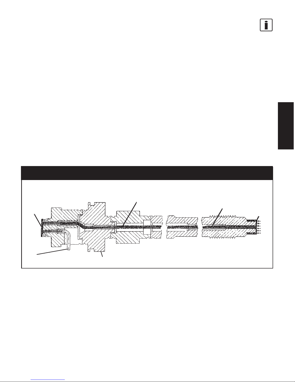
Fig. 1-1Fig. 1-1
Fig. 1-1Fig. 1-1
Fig. 1-1
Functioning Principle of the Dynisco Filled AssemblyFunctioning Principle of the Dynisco Filled Assembly
Functioning Principle of the Dynisco Filled AssemblyFunctioning Principle of the Dynisco Filled Assembly
Functioning Principle of the Dynisco Filled Assembly
The low level output signal from the bridge is amplified via an instrumentation amp circuit. The amplified
signal then goes to the input of the analog-to-digital (A/D) converter.
1.1.
1.1.
1.
77
77
7
DD
DD
D
EVICEVIC
EVICEVIC
EVIC
EE
EE
E
NN
NN
N
ETET
ETET
ET
F F
F F
F
EAEA
EAEA
EA
TURETURE
TURETURE
TURE
SS
SS
S
The PT4xxDN utilizes the DeviceNet Predefined Master Slave Connection Set operating as a Group 2 Only
Server. The PT4xxDN supports baud rates of 125K, 250k, and 500k. The node address can be set to any
address between 0 and 63. The default baud rate and node address are 125k and 63, respectively.
Pressure, alarm, and status data are available via polled I/O messages. Alarm, Warning and Scaling
parameters are configured using Explicit messages.
Filling opening
Strain gage
on the
measuring
diaphragm
Capillary with pressure
transmission fluid (Hg)
Total filling
volume = 7mm
3
Separating
diaphragm
0.15mm thick
Base of electronics housing
Page 6

6
GENERAL
1.1.
1.1.
1.
77
77
7
.1.1
.1.1
.1
II
II
I
NDICANDICA
NDICANDICA
NDICA
TT
TT
T
ORSORS
ORSORS
ORS
The PT46xDN utilizes 2 bi-color status indicators (i.e. LED’s) to report Network and Module/Device
status.
1.1.
1.1.
1.
77
77
7
.1.1
.1.1
.1
AA
AA
A
NN
NN
N
ETET
ETET
ET
WW
WW
W
ORKORK
ORKORK
ORK
SS
SS
S
TT
TT
T
AA
AA
A
TUSTUS
TUSTUS
TUS
I I
I I
I
NDICANDICA
NDICANDICA
NDICA
TT
TT
T
OROR
OROR
OR
(“A”) (“A”)
(“A”) (“A”)
(“A”)
OO
OO
O
ff:ff:
ff:ff:
ff: Transmitter is not on-line. Duplicate MAC ID check has not been completed.
GrGr
GrGr
Gr
een:een:
een:een:
een: Transmitter is on-line and is allocated to a Master.
FlFl
FlFl
Fl
aa
aa
a
shinshin
shinshin
shin
g Grg Gr
g Grg Gr
g Gr
een:een:
een:een:
een: Transmitter is on-line and has passed Duplicate MAC ID check, but is not allocated to a
Master.
Red: Red:
Red: Red:
Red: Communications Failure. Check for Duplicate MAC ID or incompatible baud rate.
Flashing Red:Flashing Red:
Flashing Red:Flashing Red:
Flashing Red: Connection timed-out.
1.1.
1.1.
1.
77
77
7
.1.1
.1.1
.1
BB
BB
B
DD
DD
D
EVICEVIC
EVICEVIC
EVIC
EE
EE
E
SS
SS
S
TT
TT
T
AA
AA
A
TUSTUS
TUSTUS
TUS
I I
I I
I
NDICANDICA
NDICANDICA
NDICA
TT
TT
T
OROR
OROR
OR
(“B”) (“B”)
(“B”) (“B”)
(“B”)
OffOff
OffOff
Off: Power is off.
GrGr
GrGr
Gr
eeneen
eeneen
een: Transmitter is operating in a normal condition.
FlFl
FlFl
Fl
aa
aa
a
shinshin
shinshin
shin
g Grg Gr
g Grg Gr
g Gr
eeneen
eeneen
een: Transmitter requires baud or address configuration.
RedRed
RedRed
Red: Open Gage or electronics fault condition. If possible, check the I/O status message for fault
condition.
1.1.
1.1.
1.
77
77
7
.2.2
.2.2
.2
I/O MI/O M
I/O MI/O M
I/O M
ESSAGINGESSAGING
ESSAGINGESSAGING
ESSAGING
The PT46xDN Transmitter supports Polled I/O Messaging to read “real-time” data. It does not support
Cyclic I/O, Change of State (COS), or Bit-Strobe connections. The control system Master must be configured
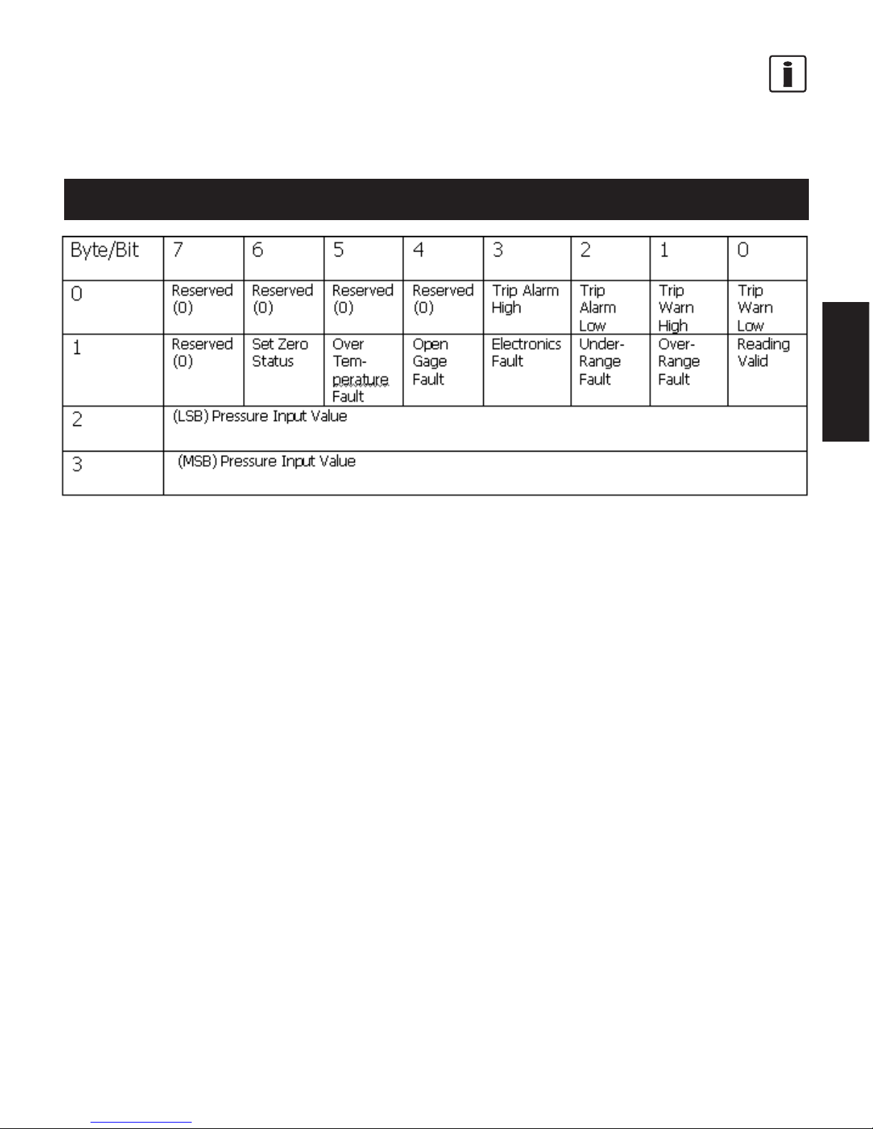
first 8-bit word (Byte 0) of the I/O Message Response as shown in Table 1. Note that the most significant
4 bits of the first byte are reserved for future use. The next 8-bit word (Byte 1) supplies transmitter status
information, e.g. reading valid, electronics fault, etc. Further information on alarm and status bits is
available in Section 7.4. The remaining 2 8-bit words (Bytes 2 & 3) represent the Pressure Value (PV).
"B" Module Status
"A" Network Status
Page 7
7
GENERAL
Refer to Section 1.7.3 for additional information in interpreting the pressure data reported in the I/O
message.
Fig. 1-1Fig. 1-1
Fig. 1-1Fig. 1-1
Fig. 1-1
DeviceNet Message Format for I/O MessagingDeviceNet Message Format for I/O Messaging
DeviceNet Message Format for I/O MessagingDeviceNet Message Format for I/O Messaging
DeviceNet Message Format for I/O Messaging
1.1.
1.1.
1.
77
77
7
..
..
.
33
33
3
II
II
I
NTERPRETINGNTERPRETING
NTERPRETINGNTERPRETING
NTERPRETING
THETHE
THETHE
THE
O O
O O
O
UTPUTUTPUT
UTPUTUTPUT
UTPUT
When reading the PV, it is important to understand how the value is scaled by the Engineering Units
parameter and the Unity Gain Reference (UGR) parameter.
The PV can be scaled to a variety of engineering units, e.g. counts, psi, bar, etc., by setting the Data Units
parameter to the appropriate value as listed in Attribute #02 of Section 7.4.
When reporting the PV in any engineering unit other than counts, a decimal scale factor called the Unity
Gain Reference (UGR) is used to convert PV to “real world” pressure. By employing the UGR, the I/O data
is presented in a more efficient integer format rather than a floating point. The UGR is factory-set and
cannot be changed.
To compute the actual pressure, the control system must simply divide the PV by the UGR (
Pressure = PV /
UGR
).
ExEx
ExEx
Ex
ampamp
ampamp
amp
ll
ll
l
e (e (
e (e (
e (
500-p500-p
500-p500-p
500-p
ss
ss
s
i Pi P
i Pi P
i P
T4T4
T4T4
T4
60DN 60DN
60DN 60DN
60DN
TT
TT
T
rr
rr
r
anan
anan
an
smittsmitt
smittsmitt
smitt
er):er):
er):er):
er):
A DeviceNet Master reads the PV via an I/O message and the UGR and Data Units via an explicitA DeviceNet Master reads the PV via an I/O message and the UGR and Data Units via an explicit
A DeviceNet Master reads the PV via an I/O message and the UGR and Data Units via an explicitA DeviceNet Master reads the PV via an I/O message and the UGR and Data Units via an explicit
A DeviceNet Master reads the PV via an I/O message and the UGR and Data Units via an explicit
message as follows:message as follows:
message as follows:message as follows:
message as follows:
PV = 3852PV = 3852
PV = 3852PV = 3852
PV = 3852
UGR = 10UGR = 10
UGR = 10UGR = 10
UGR = 10
Data Units = 4864 (PSI)Data Units = 4864 (PSI)
Data Units = 4864 (PSI)Data Units = 4864 (PSI)
Data Units = 4864 (PSI)
Page 8

8
GENERAL
The control system must compute the actual pressure as follows:The control system must compute the actual pressure as follows:
The control system must compute the actual pressure as follows:The control system must compute the actual pressure as follows:
The control system must compute the actual pressure as follows:
Pressure = 3852/10 = 385.2 psi.Pressure = 3852/10 = 385.2 psi.
Pressure = 3852/10 = 385.2 psi.Pressure = 3852/10 = 385.2 psi.
Pressure = 3852/10 = 385.2 psi.
1.1.
1.1.
1.
77
77
7
.4.4
.4.4
.4
EE
EE
E
XPLICITXPLICIT
XPLICITXPLICIT
XPLICIT
M M
M M
M
ESSAGINGESSAGING
ESSAGINGESSAGING
ESSAGING
The PT46xDN Transmitter supports explicit messaging for setup and configuration. Any DeviceNet
master that supports explicit messaging can be used in conjunction with the EDS file supplied with the
PT46xDN to configure it. Refer to Section 6.4 for a description of configurable parameters.
Page 9

9
SAFETY
2.2.
2.2.
2.
NN
NN
N
OTESOTES
OTESOTES
OTES
ONON
ONON
ON
SAFETYSAFETY
SAFETYSAFETY
SAFETY
The operator or owner of the larger overall system is responsible for following the safety
and accident prevention regulations that apply to the specific application.
DD
DD
D
YNISCYNISC
YNISCYNISC
YNISC
OO
OO
O will not be held liable for any injury, loss or damage resulting from failure to
follow the instructions in this manual.
TT
TT
T
oo
oo
o
xx
xx
x
icic
icic
ic
Haz Haz
Haz Haz
Haz
arar
arar
ar
d!d!
d!d!
d!
The PT46XDN may contain a very small amount of mercury (Hg) 0.00322 in³ typically with a
6/18 configuration, as its transmission medium. If the diaphragm is damaged, mercury
mayescape. Never transport or store the PT46XDN without the protective cap. Remove the
cap shortly before installation.
If mercury is inhaled or swallowed, seek medical attention immediately!If mercury is inhaled or swallowed, seek medical attention immediately!
If mercury is inhaled or swallowed, seek medical attention immediately!If mercury is inhaled or swallowed, seek medical attention immediately!
If mercury is inhaled or swallowed, seek medical attention immediately!
Mercury is hazardous waste and must be disposed of in accordance with applicable laws.
DD
DD
D
YNISCYNISC
YNISCYNISC
YNISC
OO
OO
O will accept defective PT’s. If mercury escapes, use airtight packaging!
TT
TT
T
emperemper
emperemper
emper
atat
atat
at
urur
urur
ur
ee
ee
e
The PT46XDN series of pressure transmitters can be used in media temperatures up to 400°C. If the
pressure transmitter is used in other applications, the safety and accident prevention regulations
specific to that application must be followed. Maximum ambient temperature for the electronics
housing is +85°C (185°F).
Higher temperature can result in damage and malfunction. Do not install the pressure transmitter in
places where this temperature is exceeded.
Page 10

10
TECHNICAL DATA
X PT46 X DN-X-X-X/XX-XXXX
Optional Temperature Sensor
0.5% Combined Error
Snout/Capillary Configuration Descriptor
DeviceNet Output
Optional Process Connections
Pressure Range
Rigid Snout (Stem)
Rigid or Flexible Capillary
Option Code
3.3.
3.3.
3.
TT
TT
T
EE
EE
E
CHNICALCHNICAL
CHNICALCHNICAL
CHNICAL
D D
D D
D
AA
AA
A
TT
TT
T
AA
AA
A
3.1 Ordering Guide for PT46XDN ................................................................................................. 10
3.2 Ordering Example ................................................................................................................ 10
3.3 Ordering Information ............................................................................................................ 10
3.4 Configuration and Temperature Option .................................................................................. 11
3.5 Process Connections ............................................................................................................ 11
3.6 Pressure Range - Full Scale................................................................................................... 12
3.7 Rigid Stem & Rigid or Flexible Capillary .................................................................................. 12
3.8 Option Codes ....................................................................................................................... 12
3.9 Output ................................................................................................................................. 12
3.10 DeviceNet Conformance .......................................................................................................13
3.11 Digital Resolution .................................................................................................................13
3.12 DeviceNet Specifications ...................................................................................................... 13
3.13 Engineering Units.................................................................................................................14
3.14 Sensor Diagnostics .............................................................................................................. 14
3.15 Performance Characteristics ................................................................................................. 14
3.15.1 Combined Error (Accuracy) .................................................................................................... 14
3.15.2 Repeatability ....................................................................................................................... 14
3.15.3 Max. Pressure (without Influencing Operating Data) .............................................................. 15
3.15.4 Burst Pressure ..................................................................................................................... 15
3.15.5 Humidity .............................................................................................................................. 15
3.16 Electrical Termination ........................................................................................................... 15
3.17 Temperature Influence ......................................................................................................... 15
3.18 Materials ............................................................................................................................. 15
3.19 Torque ................................................................................................................................. 16
3.20 Weight ................................................................................................................................16
3.21 Dimensions.......................................................................................................................... 16
3.13.1
3.13.1
3.1
OO
OO
O
RDERINGRDERING
RDERINGRDERING
RDERING
G G
G G
G
UIDEUIDE
UIDEUIDE
UIDE
FORFOR
FORFOR
FOR
PT46XDN PT46XDN
PT46XDN PT46XDN
PT46XDN
The exact meanings of the letter/digit combinations are given in the corresponding sections of
Chapter 3.
Page 11

11
TECHNICAL DATA
3.23.2
3.23.2
3.2
OO
OO
O
RDERINGRDERING
RDERINGRDERING
RDERING
E E
E E
E
XAMPLESXAMPLES
XAMPLESXAMPLES
XAMPLES
T PT46 3 DN-M18-5M-6/18-B628
Optional J Type Thermocouple
0.5% Combined Error
Thermocouple Version
DeviceNet Output
M18 Process Connections
5000 psi
6” Rigid Snout (Stem)
18” Flexible Capillary
NaK Filled
3.3.
3.3.
3.
33
33
3
OO
OO
O
RDERINGRDERING
RDERINGRDERING
RDERING
I I
I I
I
NFORMANFORMA
NFORMANFORMA
NFORMA
TIONTION
TIONTION
TION
XPT46XDN-X-X-X/XX-XXXX
3.43.4
3.43.4
3.4
CC
CC
C
ONFIGURAONFIGURA
ONFIGURAONFIGURA
ONFIGURA
TIONTION
TIONTION
TION
ANDAND
ANDAND
AND
TT
TT
T
EMPERAEMPERA
EMPERAEMPERA
EMPERA
TURETURE
TURETURE
TURE
O O
O O
O
PP
PP
P
TIONTION
TIONTION
TION
XX
XX
XPT46
XX
XX
XDN-X-X-X/XX-XXXX
Blank, 0 = No Temperature Sensor, Rigid Snout with No Capillary
Blank, 2 = No Temperature Sensor, Rigid Snout with Capillary
T, 3 = Temperature Sensor, Rigid Snout with Capillary
3.3.
3.3.
3.
55
55
5
PP
PP
P
ROCESSROCESS
ROCESSROCESS
ROCESS
C C
C C
C
ONNECTIONSONNECTIONS
ONNECTIONSONNECTIONS
ONNECTIONS
XPT46XDN-
XX
XX
X-X-X/XX-XXXX
Blank = 1/2-20 UNF
M18 = M18 x 1.5 Thread
Other process connections are available. Please consult factory
Page 12

12
TECHNICAL DATA
3.63.6
3.63.6
3.6
PP
PP
P
RESSURERESSURE
RESSURERESSURE
RESSURE
R R
R R
R
ANGEANGE
ANGEANGE
ANGE
- F - F
- F - F
- F
ULLULL
ULLULL
ULL
S S
S S
S
CALECALE
CALECALE
CALE
XPT46XDN-X-
XX
XX
X-X/XX-XXXX
psipsi
psipsi
psi
OrderOrder
OrderOrder
Order
BarBar
BarBar
Bar
OrderOrder
OrderOrder
Order
CodeCode
CodeCode
Code
CodeCode
CodeCode
Code
250 2.5C 17.5 17.5B (M18 only)
500 5C 35 35B
750 7.5C 50 50B
1000 1M 70 70B
1500 1.5M 100 1CB
3000 3M 200 2CB
5000 5M 350 3.5CB
7500 7.5M 500 5CB
10000 10M 700 7CB
15000 15M 1000 1MB
20000 20M 1400 1.4MB
30000 30M 2000 2MB
Other ranges and pressure configurations are available, please consult factory.
3.3.
3.3.
3.
77
77
7
RR
RR
R
IGIDIGID
IGIDIGID
IGID
STEMSTEM
STEMSTEM
STEM
& R & R
& R & R
& R
IGIDIGID
IGIDIGID
IGID
OROR
OROR
OR
C C
C C
C
APILLARYAPILLARY
APILLARYAPILLARY
APILLARY
XPT46XDN-X-X-
X/XXX/XX
X/XXX/XX
X/XX-XXXX
6 = 6” Rigid Stem/0” Flexible Capillary
6/18 = 6” Rigid Stem/18” Flexible Capillary
6/30 = 6” Rigid Stem/30” Flexible Capillary
12/18 = 12” Rigid Stem/18” Flexible Capillary
12/30 = 12” Rigid Stem/30” Flexible Capillary
Other lengths and configurations are available, please consult factory.
3.83.8
3.83.8
3.8
OO
OO
O
PTIONPTION
PTIONPTION
PTION
C C
C C
C
ODESODES
ODESODES
ODES
XPT46XDN-X-X-X/XX-
XXXXXXXX
XXXXXXXX
XXXX
Please consult factory for list of approved options.
3.3.
3.3.
3.
99
99
9
OO
OO
O
UTPUTUTPUT
UTPUTUTPUT
UTPUT
DeviceNet
Page 13

13
TECHNICAL DATA
3.103.10
3.103.10
3.10
DD
DD
D
EVICEEVICE
EVICEEVICE
EVICE
NN
NN
N
ETET
ETET
ET
C C
C C
C
ONFORMANCEONFORMANCE
ONFORMANCEONFORMANCE
ONFORMANCE
Conformance-Tested by ODVA Independent Test Lab (CIP protocol test, EDS test, physical layer test &
system interpretability test).
3.113.11
3.113.11
3.11
DD
DD
D
IGITIGIT
IGITIGIT
IGIT
ALAL
ALAL
AL
R R
R R
R
EE
EE
E
SOLSOL
SOLSOL
SOL
UTIONUTION
UTIONUTION
UTION
Pressure Operating 14 bits minimum (±0.01% FS or 16 ppm) typically ,
Range Resolution full scale = ~20,000 counts
3.123.12
3.123.12
3.12
DD
DD
D
EVICEVIC
EVICEVIC
EVIC
EE
EE
E
NN
NN
N
ETET
ETET
ET
SS
SS
S
PEPE
PEPE
PE
CIFICACIFICA
CIFICACIFICA
CIFICA
TIONSTIONS
TIONSTIONS
TIONS
Digital Communication Protocol DeviceNet Version 2.0, ~Errata 5
ODVA Vendor ID 852 (Dynisco Instruments)
Device Profile Generic Device 00
hex
(Refer to 1C
hex
Vacuum/
Pressure Gauge Device in DN spec. Vol. 2, 3-26 as a
guideline)
Network Power Consumption Maximum 30 mA @ 24 Vdc
Connector Style Sealed 5-pin Micro (IEC-60947-5-2)
Isolated Physical Later Non-isolated per DN spec 9-2
LED Support 2 bi-color LED’s (module and network status per
Device Net spec 8-2.)
MAC ID Setting Software selectable only. Default id = 63.
Communication Rate Setting Software selectable
Communication Rates Supported 125k (default), 250k and 500k bits/sec
Predefined Master/Slave Group only 2 server (Slave)
Connection Set
Message Types Supported Polled/Explicit
Dynamic Connections Supported (UCMM) No
Fragmented Explicit Messaging Implemented Yes
Page 14

14
TECHNICAL DATA
Alarm Setpoints 2 High and 2 Low user-setable alarm points.
Configured and transmitted via DeviceNet protocol.
Include user-defined hysteresis band.
3.133.13
3.133.13
3.13
EE
EE
E
NGINEERINGNGINEERING
NGINEERINGNGINEERING
NGINEERING
U U
U U
U
NITSNITS
NITSNITS
NITS
Counts Analog to Digital Counts o to 20000 typical
PSI pounds-force per square inch 14.503774*bar
BAR bar (Full Scale Bar)/(Full Scale Counts)*Counts
kgf/cm
2
kilogram-force per square centimeter 1.0197162*bar
MPa MegaPascal 0.1*bar
% Full Scale Percent full scale 0 to 100
3.143.14
3.143.14
3.14
SS
SS
S
ENSORENSOR
ENSORENSOR
ENSOR
D D
D D
D
IAGNOSTICSIAGNOSTICS
IAGNOSTICSIAGNOSTICS
IAGNOSTICS
Overrange Notification Yes
CPU Watchdog Error Yes
EEPROM Failure Yes
Open Gauge Detection Yes
Electronics Temperature Detection Yes
3.153.15
3.153.15
3.15
PP
PP
P
ERFORMANCEERFORMANCE
ERFORMANCEERFORMANCE
ERFORMANCE
CHARACTERISTICSCHARACTERISTICS
CHARACTERISTICSCHARACTERISTICS
CHARACTERISTICS
3.15.13.15.1
3.15.13.15.1
3.15.1
CC
CC
C
OMBINEDOMBINED
OMBINEDOMBINED
OMBINED
E E
E E
E
RRORRROR
RRORRROR
RROR
(A (A
(A (A
(A
CC
CC
C
CC
CC
C
URAURA
URAURA
URA
CYCY
CYCY
CY
))
))
)
Combined error is also known as accuracy which includes linearity, hysteresis and repeatability, and is
determined by BFSL (Best Fit Straight Line).
±0.5% of full scale
±0.75% of full scale for transmitters with ranges of 1000 psi and less with lengths greater than 36”.
3.15.23.15.2
3.15.23.15.2
3.15.2
RR
RR
R
EPEAEPEA
EPEAEPEA
EPEA
TT
TT
T
ABILITABILIT
ABILITABILIT
ABILIT
YY
YY
Y
±0.20% of full scale
Page 15

15
TECHNICAL DATA
3.15.3.15.
3.15.3.15.
3.15.
33
33
3
MM
MM
M
AXAX
AXAX
AX
. P. P
. P. P
. P
RERE
RERE
RE
SS
SS
S
SURESURE
SURESURE
SURE
( (
( (
(
WITHOUTWITHOUT
WITHOUTWITHOUT
WITHOUT
INFLINFL
INFLINFL
INFL
UENCINGUENCING
UENCINGUENCING
UENCING
OPERAOPERA
OPERAOPERA
OPERA
TINGTING
TINGTING
TING
DD
DD
D
AA
AA
A
TT
TT
T
AA
AA
A
))
))
)
2 x full scale pressure or 35,000 psi, which ever is less.
3.15.43.15.4
3.15.43.15.4
3.15.4
BB
BB
B
URSTURST
URSTURST
URST
PRESSUREPRESSURE
PRESSUREPRESSURE
PRESSURE
6 x nominal value, max. 45,000 psi
3.15.3.15.
3.15.3.15.
3.15.
55
55
5
HH
HH
H
UMIDITYUMIDITY
UMIDITYUMIDITY
UMIDITY
0 - 90% relative humidity (non-condensing)
3.163.16
3.163.16
3.16
EE
EE
E
LELE
LELE
LE
CTRICALCTRICAL
CTRICALCTRICAL
CTRICAL
TT
TT
T
ERMINAERMINA
ERMINAERMINA
ERMINA
TIONTION
TIONTION
TION
DeviceNet Micro (5 pin)
3.173.17
3.173.17
3.17
TT
TT
T
EMPERAEMPERA
EMPERAEMPERA
EMPERA
TURETURE
TURETURE
TURE
INFLINFL
INFLINFL
INFL
UENCUENC
UENCUENC
UENC
EE
EE
E
EE
EE
E
LECTRONICSLECTRONICS
LECTRONICSLECTRONICS
LECTRONICS
H H
H H
H
OUSINGOUSING
OUSINGOUSING
OUSING
Housing Temperature Range -20°C to +85°C (-5°F to +185°F)
Zero shift due to temperature change on electronics housing
PT46XDN 0.01% full scale/°F max. (0.02% f.s./°C max.)
Diaphragm (in contact with media) span shift due to temperature change on electronics housing.
PT46XDN 0.01% full scale /°F max.(0.02% f.s./°C max.)
Zero shift due to temperature change on the diaphragm.
PT46XDN 15 psi/100°F typical (27 psi/100°C)
3.183.18
3.183.18
3.18
MM
MM
M
AA
AA
A
TERIALSTERIALS
TERIALSTERIALS
TERIALS
Standard Diaphragm 15-5PH Mat. No. 1.4545 Various proprietary coatings
Standard Stem(Snout) 17-4PH Mat. No. 517400
Please note other diaphragm and stem materials may be substituted.
Page 16

16
TECHNICAL DATA
3.193.19
3.193.19
3.19
TT
TT
T
ORQUEORQUE
ORQUEORQUE
ORQUE
FORFOR
FORFOR
FOR
1/2-20 UNF P 1/2-20 UNF P
1/2-20 UNF P 1/2-20 UNF P
1/2-20 UNF P
ROCESSROCESS
ROCESSROCESS
ROCESS
C C
C C
C
ONNECTIONONNECTION
ONNECTIONONNECTION
ONNECTION
PT46XDN
max. 56.5 Nm
(500 inch-lbs.)
min. 11.3 Nm
(100 inch-lbs.)
3.203.20
3.203.20
3.20
WW
WW
W
EIGHTEIGHT
EIGHTEIGHT
EIGHT
The weight varies depending on product configuration. Average weight range is 1 to 5 pounds.
3.213.21
3.213.21
3.21
DD
DD
D
IMENSIONSIMENSIONS
IMENSIONSIMENSIONS
IMENSIONS
Page 17

17
TECHNICAL DATA
Fig. 3-1Fig. 3-1
Fig. 3-1Fig. 3-1
Fig. 3-1
PT46XDNPT46XDN
PT46XDNPT46XDN
PT46XDN
1
23
4
5
CONNECTOR PINOUT
PIN FUNCTION WIRE
1 DRAIN BA RE
2V+RED
3V-BLACK
4CAN_HWHITE
5CAN_LBLUE
(114.3mm)
1/2-20 UNF-2A
5/8 HEX
.44
11.2mm
1.06
26.8mm
.50
12.7mm
O
45° 30'
44° 30'
.307
.305
7.8mm
7.75mm
O
.414
.412
10.52mm
10.46mm
O
.214
5.44mm
RIGID SNOUT LENGTH
u
.06 (1.5mm)
.55
14mm
REF
3.75
95.25mm
4.50 + RIGID SNOUT LENGTH
u
.25 (6.35mm)
DIAGNOSTIC LED (2)
M12 MICRO
5 PIN CONNECTOR
1.50
38.1mm
O
DIAGNOSTIC LED (2)
M12 MICRO
5 PIN CONNECTOR
6.88 + FLEX LENGTH + RIGID SNOUT LENG TH
u
.25 (6.35mm)
(174.8mm)
3.750
95.3mm
.55
14mm
REF
1.50
38.1mm
SST ARMORED CABLE
.414
.412
10.52mm
10.46mm
O
.307
.305
7.8mm
7.75mm
O
45° 30'
44° 30'
.214
5.43mm
RIGID SNOUT LEN GTH
u
.06 (1.5mm)
.50
12.7mm
O
FLEX LENGTH
u
.12 (3.1mm)
.69
17.5mm
O
5/8 HEX
.42
10.7mm
O
1.25
31.8mm
1.06
27mm
1/2-20 UNF-2A
.44
11.1mm
DIAGNOSTIC LED (2)
3.75
95.3mm
.55
14mm
REF
1.50
38.1mm
Ø.307
.305
(7.8mm)
( 7.75mm)
.414
.412
10.5mm
10.5mm
O
SST ARMORED CABLE
SST ARMORED CABLE
T/C FLEX LENGTH
u
.12 (3.1mm)
+
-
+
-
2-PRONG
STANDARD
FEMALE CONN
STANDARD
MALE CONN
THERMOCOUPLE
CABLE CLAMP
45° 30'
44° 30'
.214
5.44mm
RIGID SNOUT LENGTH
u
.06 (1.5mm)
.42
10.7mm
O
1.06
26.8mm
.44
11.23mm
1/2-20 UNF-2A
.50
12.7mm
O
SET SCREW
1.25
31.8mm
O
7/8 HEX
UNIT FLEX LENGTH
u
.12 (3.1mm )
.69
17.5mm
O
M12 MICRO
5 PIN CONNECTOR
6.90 + UNIT FLEX LENGTH + RIGID SNOUT LENGTH
u
.25 (6.35mm)
(175.3mm)
Page 18

18
TRANSPORT
4.4.
4.4.
4.
TT
TT
T
RANSPORTRANSPORT
RANSPORTRANSPORT
RANSPORT
/D/D
/D/D
/D
ELIVERYELIVERY
ELIVERYELIVERY
ELIVERY
4.1 Transport/Packing/Transport Damage ...................................................................................18
4.2 Storage ............................................................................................................................... 18
4.3 Scope of Delivery ................................................................................................................. 18
TT
TT
T
oo
oo
o
xx
xx
x
icic
icic
ic
h h
h h
h
azaz
azaz
az
arar
arar
ar
d!d!
d!d!
d!
The PT contains a small amount of mercury (Hg) as its transmission medium. If the
diaphragm is damaged, mercury may escape.
Never transport or store the PT without the protective shell bolted in place. Remove the shell
shortly before installation.
If mercury is inhaled or swallowed, seek medical attention immediately.If mercury is inhaled or swallowed, seek medical attention immediately.
If mercury is inhaled or swallowed, seek medical attention immediately.If mercury is inhaled or swallowed, seek medical attention immediately.
If mercury is inhaled or swallowed, seek medical attention immediately.
Mercury is hazardous waste and must be disposed of in accordance with applicable laws.
DD
DD
D
YNISCYNISC
YNISCYNISC
YNISC
OO
OO
O will accept defective PTs.
If mercury escapes, use airtight packaging!
4.14.1
4.14.1
4.1
TT
TT
T
RANSRANS
RANSRANS
RANS
PORPOR
PORPOR
POR
TT
TT
T
//
//
/
PP
PP
P
AA
AA
A
CKINGCKING
CKINGCKING
CKING
//
//
/
TRANSTRANS
TRANSTRANS
TRANS
PORPOR
PORPOR
POR
TT
TT
T
DD
DD
D
AMAGEAMAGE
AMAGEAMAGE
AMAGE
• Do not let the PT be damaged by other items during transit.
• Use only the original packaging.
• Report transport damage to
DD
DD
D
YNISCYNISC
YNISCYNISC
YNISC
OO
OO
O immediately in writing.
4.24.2
4.24.2
4.2
SS
SS
S
TORAGETORAGE
TORAGETORAGE
TORAGE
• Store the PT in original packaging only.
• Protect against dust and moisture.
4.4.
4.4.
4.
33
33
3
SS
SS
S
CC
CC
C
OPEOPE
OPEOPE
OPE
OFOF
OFOF
OF
D D
D D
D
ELIVERYELIVERY
ELIVERYELIVERY
ELIVERY
• PT with diaphragm protection cap
• Fastening clip (transmitter with flexible stem only)
• Calibration sheet
• Operating manual with declaration of conformity
Page 19

19
I
NSTALLATION
5.5.
5.5.
5.
II
II
I
NSNS
NSNS
NS
TT
TT
T
ALLAALLA
ALLAALLA
ALLA
TIONTION
TIONTION
TION
5.1 General Mounting Information .............................................................................................. 19
5.2 Mounting Hole Torque ......................................................................................................... 20
5.3 Mounting Hole Dimensions .................................................................................................. 20
5.4 Mounting the Pressure Transmitter ........................................................................................21
5.5 DeviceNet Wiring ................................................................................................................ 22
5.6 DeviceNet Connector Wiring ................................................................................................ 22
5.15.1
5.15.1
5.1
GG
GG
G
ENERALENERAL
ENERALENERAL
ENERAL
M M
M M
M
OUNTINGOUNTING
OUNTINGOUNTING
OUNTING
I I
I I
I
NFORMANFORMA
NFORMANFORMA
NFORMA
TIONTION
TIONTION
TION
Do not remove the protective cap on the PT until ready to install.
Before mounting the PT, check mounting hole carefully. The PT must only be mounted in holes that
satisfy the requirements below. A hole that does not satisfy these requirements can damage the
Transmitter.
Insure the mounting hole is clear of any frozen polymer or debris and is machined to the proper
dimensions.
For threaded PT transmitters coat the threads with a high temperature anti-seize grease or a suitable
parting agent, this will help prevent the PT snout from sticking permanently in the mounting hole.
Install unit into the process connection. (Do NOT torque transmitter into the hole at this time!) Allow time
for the transmitter snout temperature to equalize to the process temperature. This will help eliminate
thread galling and ease removal later. There should be NO pressure applied at this time.
Always use a torque wrench applied to the designated hexagon collar or mounting bolts while screwing
the transmitter in and out. Do not apply the tool to the housing or housing/sensor connection.
After temperatures have equalized, apply proper torque as described in Section 3.20 of the Manual and
tighten transmitter into mounting hole.
After the correct torque has been applied units with flexible capillary require the electronics to be
mounted away from the process heat using mounting hardware, P/N 200941.
Make sure that the medium is in molten condition during transmitter removal. Removing the transmitter
while the medium is in solidified condition can damage the sensor diaphragm.
When removing the PT, carefully clean the diaphragm of the transmitter with a soft cloth while the
medium is still malleable.
Page 20

20
INSTALLATION
Always remove the PT prior to cleaning the machine with abrasives or steel wire brushes. Also, do not
clean the PT with hard objects, such as a screwdriver, a wire brush, etc. this will possibly damage the
transmitter.
Before reinstalling the PT, ensure that the mounting hole is free from hardened plastic. A mounting hole
cleaning tool kit is available to aid in removing of the material. (Dynisco Part Number 200100 for ½-20,
200101 for M18 and 200102 for M10 ports.) A gauge plug to check the hole is included in this kit.
The most common causes of transducer damage are: installation in improperly machined or plugged
mounting holes and cold starts. The tip of the transducer consists of a stainless steel diaphragm that
must be protected from severe abrasives, dents and scores.
Burn Hazard!Burn Hazard!
Burn Hazard!Burn Hazard!
Burn Hazard!
The PT must be removed with the melt in the molten condition. The PT can be very hot
when removed. WEAR PROTECTIVE GLOVES!
Careful attention should be paid to correctly machine the mounting port. Failure to use the
recommended mounting port may result in erroneous pressure measurement, difficult transducer
removal, premature sensor failure, process fluid leaks, and personnel hazard. In applications involving
high temperature operation and/or repeated thermal cycling a good high quality anti-seize compound
should be applied to the threaded surfaces.
5.25.2
5.25.2
5.2
MM
MM
M
OUNTINGOUNTING
OUNTINGOUNTING
OUNTING
H H
H H
H
OLEOLE
OLEOLE
OLE
T T
T T
T
ORQUEORQUE
ORQUEORQUE
ORQUE
PT46XDN
max. 56.5 Nm
(500 inch-lbs.)
min. 11.3 Nm
(100 inch-lbs.)
5.5.
5.5.
5.
33
33
3
MM
MM
M
OUNTINGOUNTING
OUNTINGOUNTING
OUNTING
H H
H H
H
OLEOLE
OLEOLE
OLE
D D
D D
D
IMENSIONSIMENSIONS
IMENSIONSIMENSIONS
IMENSIONS
Drill the mounting hole as shown in Fig. 5-1.
Please consult factory for other mounting configurations.
Page 21

21
I
NSTALLATION
5.45.4
5.45.4
5.4
MM
MM
M
OUNTINGOUNTING
OUNTINGOUNTING
OUNTING
THETHE
THETHE
THE
P P
P P
P
RESSURERESSURE
RESSURERESSURE
RESSURE
T T
T T
T
RANSMITTERRANSMITTER
RANSMITTERRANSMITTER
RANSMITTER
Dynisco offers a set of mounting hole-machining tools with all the necessary drills, taps, and reamers
for the Dynisco standard ½-20UNF-2A and M18 and M10 mounting holes used in high temperature and
plastics processing applications (Dynisco Part Numbers 200925, 200105 and 901949 respectively).
Detailed instructions are sent with the machining kits. Copies of the instructions are available from
Dynisco upon request.
When machining the hole pay careful attention to the concentricity between the threads and the 0.312/
0.314 diameter. Since the pressure seal is on the 45° seating surface, this surface should be examined
for good finish, free from burrs, etc.
It is general good practice to check the mounting hole before installing the transducer. One procedure
is to coat a gauge plug (Dynisco Part Number 200908 for the 1/2 –20 standard port, 435901 for the
short tip 1/2 –20 version, 200960 for the M18), with Dykem machine bluing on surfaces below the
thread. Insert the gauge plug into the mounting hole and rotate until surface binding is encountered.
Remove and inspect. Bluing should only be scraped off of the 45° sealing chamfer. If bluing has been
removed from other surfaces, the mounting hole has not been machined properly.
Fig. 5-1Fig. 5-1
Fig. 5-1Fig. 5-1
Fig. 5-1
PT46XDN (1/2-20 UNF) Mounting Hole PT46XDN (1/2-20 UNF) Mounting Hole
PT46XDN (1/2-20 UNF) Mounting Hole PT46XDN (1/2-20 UNF) Mounting Hole
PT46XDN (1/2-20 UNF) Mounting Hole
Page 22

22
INSTALLATION
5.5.
5.5.
5.
55
55
5
DD
DD
D
EVICEEVICE
EVICEEVICE
EVICE
NN
NN
N
ETET
ETET
ET
W W
W W
W
IRINGIRING
IRINGIRING
IRING
The PT46XDN can be readily connected to the DeviceNet bus using the optional connector and cable
assembly or a customer-supplied connector and cable. It is important to adhere to proper DeviceNet wiring
practices. The DeviceNet Technical Overview available from the Open DeviceNet Vendors Association
(www.odva.org) provides additional information on DeviceNet physical layer topologies including cable
types, trunk and drop lengths, and terminating resistors.
It is recommended that all wiring be validated using a media checker to identify potential media problems,
e.g. shorts, opens, excessive cable length, and crossed connections.
5.65.6
5.65.6
5.6
DD
DD
D
EVICEEVICE
EVICEEVICE
EVICE
NN
NN
N
ETET
ETET
ET
C C
C C
C
ONNECTORONNECTOR
ONNECTORONNECTOR
ONNECTOR
W W
W W
W
IRINGIRING
IRINGIRING
IRING
The DeviceNet Pressure Transmitter uses the standard DeviceNet Micro DIN 5-pin connector. The
connections are as follows:
Cable Leads To Connector Pin
Black -V 3
Blue CAN-L 5
Bare Drain 1
White CAN-H 4
Red +V 2
CONNECTOR PINOUT
1
2
3
4
5
Page 23

23
CONFIGURATION
6.6.
6.6.
6.
CC
CC
C
ONFIGURAONFIGURA
ONFIGURAONFIGURA
ONFIGURA
TIONTION
TIONTION
TION
6.1 Initializing DeviceNet Communications ................................................................................. 23
6.2 Setting the Node Address and Baud Rate ............................................................................. 23
6.3 Electronic Data Sheet File (EDS) ........................................................................................... 23
6.4 Parameter Configuration ..................................................................................................... 24
6.16.1
6.16.1
6.1
II
II
I
NITIALIZINGNITIALIZING
NITIALIZINGNITIALIZING
NITIALIZING
D D
D D
D
EVICEVIC
EVICEVIC
EVIC
EE
EE
E
NN
NN
N
ETET
ETET
ET
C C
C C
C
OMMUNICAOMMUNICA
OMMUNICAOMMUNICA
OMMUNICA
TIONSTIONS
TIONSTIONS
TIONS
When the transmitter is connected to the DeviceNet bus, it will perform an initialization sequence to
establish communications with the Master.
1. Initially, the Device Status LED will flash red one time, and then will change to a steady green.
At this point the Transmitter has passed its internal health check.
2. Simultaneously, the Network Status LED will flash green one time, then after a few seconds
will continue to flash green.
3. At this point, the duplicate MAC ID check is complete, and the transmitter is waiting to be
allocated to a Master.
4. If the Network status LED stays solid red, remove the connector and then reconnect. If the
LED is still solid red, continue to section 6.2 Setting the Node Address and Baud Rate
6.26.2
6.26.2
6.2
SS
SS
S
ETET
ETET
ET
TINGTING
TINGTING
TING
THETHE
THETHE
THE
N N
N N
N
ODEODE
ODEODE
ODE
A A
A A
A
DDREDDRE
DDREDDRE
DDRE
SS
SS
S
SS
SS
S
ANDAND
ANDAND
AND
B B
B B
B
AA
AA
A
UDUD
UDUD
UD
R R
R R
R
AA
AA
A
TETE
TETE
TE
The Node Address and Baud Rate are set via explicit messaging by means of any commercially-available
DeviceNet configuration tool.
1. The default node address is
63,63,
63,63,
63, and the default baud rate is
125K125K
125K125K
125K.
2. If the node address is changed, the DeviceNet Pressure Transmitter will reinitialize prior to assuming
the new node address.
3. If the baud rate is changed, it is necessary to disconnect the transmitter from the network. The
transmitter will assume the new baud rate once it is reconnected to the network and it has
reinitialized.
66
66
6
..
..
.
33
33
3
EE
EE
E
LELE
LELE
LE
CTRONICCTRONIC
CTRONICCTRONIC
CTRONIC
D D
D D
D
AA
AA
A
TT
TT
T
AA
AA
A
SS
SS
S
HEETHEET
HEETHEET
HEET
F F
F F
F
ILEILE
ILEILE
ILE
(ED (ED
(ED (ED
(ED
S)S)
S)S)
S)
The EDS or Electronic Data Sheet file for the Dynisco DeviceNet Pressure Transducer is named PT46XDN.EDS
and is available online at www.dynisco.com. The EDS file is used to automate the DeviceNet network
configuration process by precisely defining vendor-specific and required device parameter information.
Page 24

24
CONFIGURATION
The EDS file describes a device’s configurable parameters, including its legal and default values and the
public interfaces to those parameters. Software configuration tools utilize the EDS files to configure a
DeviceNet network.
6.46.4
6.46.4
6.4
PP
PP
P
ARAMETERARAMETER
ARAMETERARAMETER
ARAMETER
C C
C C
C
ONFIGURAONFIGURA
ONFIGURAONFIGURA
ONFIGURA
TIONTION
TIONTION
TION
After the baud rate and node address have been established, the device parameters are ready to be
configured. The following configurable parameters are available (see Section 7.4 for more information):
1. Data Units (Attribute #02 / Default is “counts”)
The Pressure Value (PV) can be scaled to a variety of engineering units by configuring the Data units
to digital counts, PSI, bar, kg/cm^2, MPa or % full scale.
2. Alarm and Warn Status Enable (Attribute #06 and #07 / Default is “disabled”)
The respective parameters must be set (i.e. enabled) if the master will use the alarm or warning bits in
the I/O message.
3. Alarm Trip Point High and Low (Attribute #13 and #14)
These values (and the Hysteresis) define under what conditions the Alarm High and Low status bits are
set in the I/O message.
4. Alarm Trip Point Hysteresis (Attribute #15)
This value (and the Alarm Trip Point High and Low values) define under what conditions the Alarm High
and Low status bits are set in the I/O message.
5. Warning Trip Point High and Low (Attribute #17 and #18)
These values (and the Hysteresis) define under what conditions the Warn High and Low status bits are
set in the I/O message.
6. Warning Trip Point Hysteresis (Attribute #19)
This value (and the Warn Trip Point High and Low values) define under what conditions the Warn High
and Low status bits are set in the I/O message.
7. Set Zero Service (for zeroing effects of temperatures and mounting position)
Execute this service to zero the PV output. Refer to Section 7.3 for more information.
Page 25

25
CONFIGURATION
77
77
7
..
..
.
DD
DD
D
EVICEEVICE
EVICEEVICE
EVICE
NN
NN
N
ETET
ETET
ET
O O
O O
O
BJECTBJECT
BJECTBJECT
BJECT
M M
M M
M
ODELODEL
ODELODEL
ODEL
7.1 Object Model ....................................................................................................................... 25
7.2 Dynisco Pressure Sensor Object ............................................................................................ 25
7.3 Set Zero Service ................................................................................................................... 25
7.4 DeviceNet Class Attributes .................................................................................................... 25
77
77
7
.1.1
.1.1
.1
OO
OO
O
BJECTBJECT
BJECTBJECT
BJECT
M M
M M
M
ODELODEL
ODELODEL
ODEL
Objects Present in the DeviceNet Pressure Transmitter
ObjectObject
ObjectObject
Object
Optional/RequiredOptional/Required
Optional/RequiredOptional/Required
Optional/Required
# of Instances# of Instances
# of Instances# of Instances
# of Instances
Identity (1) Required 1 Message
Router (2) Required 1
DeviceNet (3) Required 1
Assembly (4) Required 1
Connection (5) Required 3
Parameter (15) Required 1
Pressure (100) Required 22
77
77
7
.2.2
.2.2
.2
DD
DD
D
YNISCYNISC
YNISCYNISC
YNISC
OO
OO
O
P P
P P
P
RERE
RERE
RE
SS
SS
S
SURESURE
SURESURE
SURE
SS
SS
S
ENSORENSOR
ENSORENSOR
ENSOR
O O
O O
O
BJEBJE
BJEBJE
BJE
CTCT
CTCT
CT
This class covers the entire Pressure Sensor and acts as an interface to the PLC.
Class ID: 100
77
77
7
..
..
.
33
33
3
SS
SS
S
ETET
ETET
ET
Z Z
Z Z
Z
EROERO
EROERO
ERO
S S
S S
S
ERVICEERVICE
ERVICEERVICE
ERVICE
There is one manufacturer-specific service to start “SetZero” functionality. The service acts as a “tare”
function by offsetting the current pressure value by the pressure value at the time the service is
invoked. This is typically used to eliminate a zero shift which may occur at elevated temperature. The
service code is 100
dec
(64
hex
). There are no parameters associated with this service.
77
77
7
.4.4
.4.4
.4
DD
DD
D
EVICEEVICE
EVICEEVICE
EVICE
NN
NN
N
ETET
ETET
ET
C C
C C
C
LASSLASS
LASSLASS
LASS
A A
A A
A
TTRIBUTESTTRIBUTES
TTRIBUTESTTRIBUTES
TTRIBUTES
The Table below shows the mapping of the DeviceNet Class Attributes.
The DeviceNet Class is always 100
dec
(64
hex
), and the Instance is always 01
.
Page 26

26
CONFIGURATION
AttributeAttribute
AttributeAttribute
Attribute
AccessAccess
AccessAccess
Access
DescriptionDescription
DescriptionDescription
Description
DatDat
DatDat
Dat
a a
a a
a
TT
TT
T
ypeype
ypeype
ype
VV
VV
V
aluealue
aluealue
alue
ID ID
ID ID
ID
RuleRule
RuleRule
Rule
(Decimal)(Decimal)
(Decimal)(Decimal)
(Decimal)
01 Get Data Type – Constant UINT C7
hex
always returns Hex C7
02 Get/Set Data Unit/Engineering UINT Hex (Decimal)
Units 4097
dec
(1001
hex
) = counts
4864
dec
(1300
hex
) = psi
4871
dec
(1307
hex
) = bar
2048
dec
(0800
hex
) = kg/cm
2
2049
dec
(0801
hex
) = MPa
4103
dec
(1007
hex
) = % FS
03 Get Device Status BIT 0=clear; 1 =set
ReadingValid: Bit 0: Reading Valid
1 = PV (Attr. 04) is valid,
0 = PV is invalid.
OverRangeFault: Bit 1:OverRangeFault
PV > OverRangeValue
UnderRangeFault: Bit 2: UnderRangeFault
PV < UnderRangeValue
EEPROM/CPUFault: Bit 3: EEPROM/CPU Fault
EEPROM or WatchDog Timer failure
OpenGageFault: Bit 4: OpenGaugeFault
Failure of strain gage bridge
OverTemperatureFault: Bit 5: OverTemperatureFault
Electronics Temp. exceeds factory limit
SetZeroStatus: Bit 6: SetZeroStatus
1 = Set zero in progress
0 = Set zero not in progress
Bits 0-7 are also available Bit 7: Reserved (0)
via Bytes #1 & #2 of the I/O
message (see section 1.7.3)
Page 27

27
CONFIGURATION
AttributeAttribute
AttributeAttribute
Attribute
AccessAccess
AccessAccess
Access
DescriptionDescription
DescriptionDescription
Description
DatDat
DatDat
Dat
a a
a a
a
TT
TT
T
ypeype
ypeype
ype
VV
VV
V
aluealue
aluealue
alue
ID ID
ID ID
ID
RuleRule
RuleRule
Rule
(Decimal)(Decimal)
(Decimal)(Decimal)
(Decimal)
04 Get PressureValue (PV) UINT
PV is in Engineering
Units as defined by
Attribute # 2. PV is
affected by Set Zero
Service (see Section 7.3).
When interpreting the
PV, be sure to account
for the UnityGainRef
(see Attr #12).
05 Get Alarm/Warn Status BYTE 0=cleared, 1=set
TripWarnLow is set when Bit 0: TripWarnLow
PV <= WarnTripPointLow
TripWarnHigh is set when Bit 1: TripWarnHigh
PV >= WarnTripPointHigh
TripAlarmLow is set when Bit 2: TripAlarmLow
PV <= AlarmTripPointLow
TripAlarmHigh is set when Bit 3: TripAlarmHigh
PV >= AlarmTripPointHigh
Note: AlarmEnable or Warning Bit 4 to 7: Reserved
Enable Attributes must be set
to enable the Alarm/Warn status bits.
06 Get/Set AlarmEnable BIT 0 = Disable (default)
1 = Enable
07 Get/Set WarnEnable BIT 0 = Disable (default)
1 = Enable
08 Get SensorFullScaleValue UINT Maximum allowable value FFFF
hex
09 Get Offset A INT Factory use only
10 Get Offset B INT Factory use only
Page 28

28
CONFIGURATION
AttributeAttribute
AttributeAttribute
Attribute
AccessAccess
AccessAccess
Access
DescriptionDescription
DescriptionDescription
Description
DatDat
DatDat
Dat
a a
a a
a
TT
TT
T
ypeype
ypeype
ype
VV
VV
V
aluealue
aluealue
alue
ID ID
ID ID
ID
RuleRule
RuleRule
Rule
(Decimal)(Decimal)
(Decimal)(Decimal)
(Decimal)
11 Get Gain UINT Factory use only
12 Get Unity Gain Reference UINT
(UGR) Decimal scale
factor used to convert
PV to “real world”
pressure. Pressure =
PV / UGR. Note that the
UGR is fixed for each
transducer range.
13 Get AlarmTripPointHigh UINT Valid Range:
(ATPH) If AlarmEnable
is set and PV >= ATPH, (WTPH - Alarm Hysteresis)
TripAlarmHigh is set <= ATPH <= Overrange
(see Attr 05).
TripAlarmHigh is cleared
once PV <= ATPH –
AlarmHysteresis
(see Attr 15)
14 Get/Set AlarmTripPointLow UINT Valid Range:
(ATPL) If AlarmEnable
is set and PV <= ATPL, Underrange <= ATPL <=
TripAlarmLow is set (WTPL - AlarmHysteresis)
(see Attr 05).
TripAlarmLow is cleared
once PV >= ATPL +
AlarmHysteresis (see Attr 15).
15 Get/Set AlarmHysteresis UINT Valid Range:
The amount by which
PV must recover to clear AlarmHysteresis <=
either TripAlarmHigh or (ATPH - WTPH) or
TripAlarmLow. (WTPL - ATPL)
16 Get/Set AlarmSettlingTime UINT Units are in milliseconds
The time that the PV
must exceed the trip point
before TripAlarmHigh or
TripAlarmLow is set.
Page 29

29
CONFIGURATION
AttributeAttribute
AttributeAttribute
Attribute
AccessAccess
AccessAccess
Access
DescriptionDescription
DescriptionDescription
Description
DatDat
DatDat
Dat
a a
a a
a
TT
TT
T
ypeype
ypeype
ype
VV
VV
V
aluealue
aluealue
alue
ID ID
ID ID
ID
RuleRule
RuleRule
Rule
(Decimal)(Decimal)
(Decimal)(Decimal)
(Decimal)
17 Get/Set WarnTripPointHigh UINT Valid Range:
(WTPH) If WarnEnable
is set and PV >= WTPH, (WTPL + WarmHysteresis) <=
TripWarnHigh is set WTPH <=
(see Attr. 05) (ATPH - AlarmHysteresis)
TripWarnHigh is cleared
once PV <= WTPH –
WarnHysteresis (see Attr 19).
18 Get/Set WarnTripPointLow UINT Valid Range:
(WTPL)If AlarmEnable is
set and PV <= WTPL, (ATPL + AlarmHysteresis) <=
TripWarnLow is set WTPH <= WarnHysteresis
(see Attr. 05)TripWarnLow
is cleared once PV >= WTPL
+ WarnHysteresis (see Attr 19).
19 Get/Set WarnHysteresis UINT Valid Range:
The amount by which
PV must recover to clear WarnHysteresis <=
either T ripW arnHigh (WTPH - WTPL)
or TripWarnLow.
20 Get/Set WarnSettlingTime UINT Units are in milliseconds
The time that the PV
must exceed the trip
point before T ripW arnHigh
or T ripW arnLow is set.
21 Get OverRange UINT
If PV > OverRange,
then OverRangeF ault
is set (see Attr. 03).
22 Get UnderRange UINT
If PV < UnderRange,
then UnderRangeF ault
is set (see Attr. 03).
25 Set Execute Rezero SINT
When set tol, unit
is rezeroed
Page 30

30
MAINTENANCE
8.8.
8.8.
8.
MM
MM
M
AINTENANCEAINTENANCE
AINTENANCEAINTENANCE
AINTENANCE
8.1 Maintenance ...................................................................................................................... 30
8.2 Thermocouple/RTD Replacement ......................................................................................... 30
8.3 Repair/Disposal ................................................................................................................... 31
8.4 Warranty ............................................................................................................................ 32
8.18.1
8.18.1
8.1
MM
MM
M
AINTENANCEAINTENANCE
AINTENANCEAINTENANCE
AINTENANCE
Burn hazard!Burn hazard!
Burn hazard!Burn hazard!
Burn hazard!
The PT must be removed with the melt in molten condition. The PT can be very hot when
removed.
Wear protective gloves!Wear protective gloves!
Wear protective gloves!Wear protective gloves!
Wear protective gloves!
Installation and Removal Instructions
• DO NOT REMOVE PROTECTIVE CAP UNTIL READY TO INSTALL.
• PRIOR TO INITIAL INSTALLATION, VERIFY CORRECT MACHINING OF MOUNTING HOLE.
• WHEN REINSTALLING, MAKE SURE MOUNTING HOLE IS CLEAR OF DEBRIS OR HARDENED
PLASTIC.
• THE MEDIUM MUST BE IN MOLTEN CONDITION DURING TRANSDUCER REMOVAL.
(Removing the transducer with the medium in a solidified condition can damage the
sensor diaphragm.)
• ALWAYS REMOVE THE PT BEFORE CLEANING THE MACHINE WITH ABRASIVES OR STEEL
WIRE BRUSHES, ETC.
• DO NOT CLEAN THE “SCREWED-IN” SECTION OF THE PT WITH HARD OBJECTS – THIS
WILL DAMAGE THE PT.
• ALWAYS USE A TORQUE WRENCH APPLIED TO THE DESIGNATED HEXAGONAL COLLAR
WHEN SCREWING THE PT IN AND OUT. DO NOT APPLY THE TOOL TO THE HOUSING OR
HOUSING/ SENSOR CONNECTION.
• ELECTROSTATIC DISCHARGE MAY DAMAGE THE PT – TAKE ESD PRECAUTIONS.
8.28.2
8.28.2
8.2
TT
TT
T
HERMOCHERMOC
HERMOCHERMOC
HERMOC
OUPLEOUPLE
OUPLEOUPLE
OUPLE
/R/R
/R/R
/R
TT
TT
T
D RD R
D RD R
D R
EPLAEPLA
EPLAEPLA
EPLA
CC
CC
C
EMENTEMENT
EMENTEMENT
EMENT
1. To remove, loosen setscrew on side of snout.
2. Without twisting, pull the thermocouple probe or RTD stem carefully out of snout.
3. To install, align slot on probe stem with pressure capillary tube and press into snout carefully
until top of probe shoulders against snout.
4. Lock in place with setscrew.
Page 31

31
MAINTENANCE
Fig. 7-1Fig. 7-1
Fig. 7-1Fig. 7-1
Fig. 7-1
ThermocoupleThermocouple
ThermocoupleThermocouple
Thermocouple
88
88
8
..
..
.
33
33
3
RR
RR
R
EPEP
EPEP
EP
AIRAIR
AIRAIR
AIR
//
//
/
DISDIS
DISDIS
DIS
POPO
POPO
PO
SS
SS
S
ALAL
ALAL
AL
TT
TT
T
oo
oo
o
xx
xx
x
icic
icic
ic
h h
h h
h
azaz
azaz
az
arar
arar
ar
d!d!
d!d!
d!
The PT contains a small amount of mercury (Hg) as its transmission medium. If the
diaphragm is damaged, mercury may escape.
Never transport or store the PT without the protective cap bolted in place. Remove the cap
shortly before installation.
If mercury is inhaled or swallowed, seek medical attention immediately!If mercury is inhaled or swallowed, seek medical attention immediately!
If mercury is inhaled or swallowed, seek medical attention immediately!If mercury is inhaled or swallowed, seek medical attention immediately!
If mercury is inhaled or swallowed, seek medical attention immediately!
Mercury is hazardous waste and must be disposed of in accordance with applicable laws.
DD
DD
D
YNISCYNISC
YNISCYNISC
YNISC
OO
OO
O will accept defective PTs.
If mercury escapes, use airtight packaging!
Page 32

32
MAINTENANCE
Please send defective PT units back to your DYNISCO representative. For DYNISCO addresses, see the
back cover of the operating manual.
8.48.4
8.48.4
8.4
WW
WW
W
ARRANTYARRANTY
ARRANTYARRANTY
ARRANTY
Dynisco Pressure transmitters will provide excellent service and superior performance if proper care is
taken during handling, installation, and use. This DYNISCO product is warranted under terms and
conditions set forth in the DYNISCO web pages. Go to www.dynisco.com and click “warranty” at the
bottom of any page for complete details.
Page 33

33
ACCESSORIES
9.9.
9.9.
9.
AA
AA
A
CC
CC
C
CC
CC
C
EE
EE
E
SS
SS
S
SORIESORIE
SORIESORIE
SORIE
SS
SS
S
• Machining tool kit 1/2”-20UNF-2A P/N 200295
• Cleaning tool kit 1/2”-20UNF-2A P/N 200100
Page 34

34
TROUBLESHOOTING
10.10.
10.10.
10.
TT
TT
T
ROUBLESHOOTINGROUBLESHOOTING
ROUBLESHOOTINGROUBLESHOOTING
ROUBLESHOOTING
SymptomSymptom
SymptomSymptom
Symptom
Corrective ActionsCorrective Actions
Corrective ActionsCorrective Actions
Corrective Actions
Output Not at Zero 1) Preform Set Zero Service
Output is Negative at Zero Pressure 1) Process temperature has cooled down since last Set
Zero. Wait for process to fully heat up to operating
temperature.
2) Transducer has lost its fill due to diaphragm damage or
rupture.
Large Zero Shift when screwing 1) Check mounting hole for frozen polymer.
in to mounting hole 2) Check transdcuer tip for damage
3) Check mounting hole for concentricity by using gauge
plug in transducer cleaning tool kit (p/n 200100) to check
for side loading of the transducer tip. Dykem bluing should
only be rubbed off at the 45° sealing surface and threads.
Rework hole to proper specifications.
4) Check mounting torque is within specifications.
No response to changes in 1) Check Port/Piping for blockage or solidified polymer
applied pressure 2) Check Transducer tip for diaphragm damage, rupture or
missing
3) Check Flexible Capillary for visible damage like
pinched, Crushed, over-extended armor on the capillary
Output not linear 1) Check for dented diaphragm
2) Check for frozen polymer on tip
Erroneous Pressure Reading 1) Check Data Units/Engineering units for correct setting
2) Was Transmitter zeroed at process operating
temperature with no pressure applied
3) Check mounting hole for proper depth dimension.
Transmitter tip may be recessed too far from polymer flow
and pressure sensing may be deadened from polymer
buildup in from of tip
4) Check mounting hole for concentricity by using Gauge
Plug in transducer cleaning tool kit (P/N 200100) to check
for side loading of transducer tip. Dykem bluing should
only be rubbed off at the 45° sealing surface and threads
5) Remove and check Transmitter tip for damage. Tip
face should be free of dents or tears in the diaphragm
material. It should be completely flat and free of frozen
polymer
Page 35

35
TROUBLESHOOTING
6) Always insure that mounting hole is clear of frozen
polymer or any other obstruction before mounting the
transmitter
7) Check Flexible Capillary for any visible damage like
pinched, crushed, over-extended armor on the capillary
No Communications 1) Check wiring, particularly continuity and polarity of the
CAN-H and CAN-L connections to the Scanner. If these are
reversed it will not communicate
2)Make sure 24 volts is present on V+ and V+ and that the
power supply for the bus is of sufficient ampere rating for
the amount of devices on the network
3) Using a DeviceNet configuration tool, check to see if
all devices on the network are set to the same baud rate
including the Scanner card
4) Using a DeviceNet configuration tool, check to see if
there are any duplicate Node Addresses (MAC-ID) on the
network, if so assign a new address to one of the
conflicting devices
5) Ensure that the network is configured correctly and the
Scanlist has downloaded correctly to the DeviceNet
Scanner
6) Verify that the EDS file in use is correct and or the latest
version (Available on the Dynisco website
www.dynisco.com)
7) Verify that the maximum line length for the baud rate
selected is not exceeded (See chart below)
Baud RateBaud Rate
Baud RateBaud Rate
Baud Rate
125K125K
125K125K
125K
250K250K
250K250K
250K
500K500K
500K500K
500K
Thick Trunk 500m (1640 ft) 250m (820 ft) 100m (328 ft)
Thin Trunk 100m (328 ft) 100m (328 ft) 100m (328 ft)
Max Drop 6m (20 ft) 6m (20 ft) 6m (20 ft)
Cumulative Drop 156m (512 ft) 78m (256 ft) 39m (128 ft)
8) Ensure that both ends of the DeviceNet network trunk
line are correctly terminated with 121 ohm resistors.
9) Ensure that no drop line devices on a trunk network
have termination fitted
10) Replace faulty Transmitter with one of a like model
and see if problem still exists, if so the problem resides in
the network
Page 36

36
CE-DECLARATION
11.11.
11.11.
11.
CC
CC
C
EE
EE
E
D D
D D
D
EE
EE
E
CLARACLARA
CLARACLARA
CLARA
TIONTION
TIONTION
TION
OFOF
OFOF
OF
C C
C C
C
ONFORMITONFORMIT
ONFORMITONFORMIT
ONFORMIT
YY
YY
Y
Page 37

37
CE-DECLARATION
12.12.
12.12.
12.
ODOD
ODOD
OD
VV
VV
V
A DA D
A DA D
A D
EE
EE
E
CLARACLARA
CLARACLARA
CLARA
TIONTION
TIONTION
TION
OFOF
OFOF
OF
C C
C C
C
ONFORMITONFORMIT
ONFORMITONFORMIT
ONFORMIT
YY
YY
Y
Page 38

38
CE-DECLARATION
Page 39

OPERATING MANUAL
13.13.
13.13.
13.
AA
AA
A
PPENDIXPPENDIX
PPENDIXPPENDIX
PPENDIX
1 - T 1 - T
1 - T 1 - T
1 - T
ERMSERMS
ERMSERMS
ERMS
ANDAND
ANDAND
AND
D D
D D
D
EFINITIONSEFINITIONS
EFINITIONSEFINITIONS
EFINITIONS
AddressAddress
AddressAddress
Address – A unique ID assigned to each device on the Network.
AlarmAlarm
AlarmAlarm
Alarm – A software trigger point to where a bit is set to 1 to indicate a pressure level has been reached.
AttributeAttribute
AttributeAttribute
Attribute – A subset of the instance that holds the particular information and status for each Instance.
ClassClass
ClassClass
Class – Defined Objects including Identity, Message Router, DeviceNet, Assembly, Connection, and
Acknowledge Handler Objects.
CC
CC
C
onfiguronfigur
onfiguronfigur
onfigur
ation ation
ation ation
ation
TT
TT
T
oooo
oooo
oo
ll
ll
l – Device or Software used in commissioning of the Slave Device to change the MAC-
ID and Baud rate.
DeviceNetDeviceNet
DeviceNetDeviceNet
DeviceNet – A low cost Open Network designed to connect a multitude of industrial sensors to
eliminate extensive Hardwiring.
DiaphragmDiaphragm
DiaphragmDiaphragm
Diaphragm – The actual sensing area of the device in contact with the process.
DrDr
DrDr
Dr
opop
opop
op – The thin Transmission media that connects the device to the Trunk.
EDSEDS
EDSEDS
EDS – Electronic Data Sheet
HysteresisHysteresis
HysteresisHysteresis
Hysteresis – A threshold band to where no change takes place to the alarm
InstanceInstance
InstanceInstance
Instance – A subset of the Object class that holds certain parameters.
MAMA
MAMA
MA
CC
CC
C
-ID-ID
-ID-ID
-ID – Also referred to as Address.
MasterMaster
MasterMaster
Master – The consuming device on the network that all slaves transmit data to.
NodeNode
NodeNode
Node – A device on the network that is connected to any point in the trunk and is in communication
with the master.
ObjectObject
ObjectObject
Object – A function or program in the device that can be internal to the device or visible to the
DeviceNet network and can include Identity, Message Router, Connection and DeviceNet network
Management.
Polling I/OPolling I/O
Polling I/OPolling I/O
Polling I/O – A function to where the slave device transmits data only when requested by a Master.
ScanlistScanlist
ScanlistScanlist
Scanlist – A database or map stored in the DeviceNet master containing all information used to
communicate with all slaves on the network.
Page 40

OPERATING MANUAL
Scanner Scanner
Scanner Scanner
Scanner – A Host or Master device that requests and sends information to any node on the network.
This device holds a table of all devices on the network.
SlaveSlave
SlaveSlave
Slave – The producing device on the network that sends its information to the Master.
SnoutSnout
SnoutSnout
Snout – The threaded section of the Transducer that mounts to the process.
Strain GaugeStrain Gauge
Strain GaugeStrain Gauge
Strain Gauge – A device whose electrical resistance varies in proportion to the amount of strain or
mechanical surface movement applied to the device.
TT
TT
T
ruru
ruru
ru
nknk
nknk
nk – The Thick transmission media used to carry network traffic over long distances.
Page 41

OPERATING MANUAL
14.14.
14.14.
14.
AA
AA
A
PPENDIXPPENDIX
PPENDIXPPENDIX
PPENDIX
2 - R 2 - R
2 - R 2 - R
2 - R
EVISIONEVISION
EVISIONEVISION
EVISION
H H
H H
H
ISTORYISTORY
ISTORYISTORY
ISTORY
Revision A (3/22/04) – Initial Release
Revision B (4/4/05) - Added Calibration Coefficients
Revision C (5/11/05) - Changed Parameter to Allow for Lower Ranges
Revision D (6/1/05) - Added Rezero Parameter
Page 42

Visit us on the world wide web:Visit us on the world wide web:
Visit us on the world wide web:Visit us on the world wide web:
Visit us on the world wide web:
wwwwww
wwwwww
www
..
..
.
dydy
dydy
dy
nini
nini
ni
ss
ss
s
cc
cc
c
oo
oo
o
..
..
.
cc
cc
c
omom
omom
om
DyniscoLLC
38 Forge Parkway
Franklin, MA 02038
USA
Tel: +1 508 541 9400
Fax: +1 508 541 9436
Email: InfoInst@dynisco.com
Dynisco Extrusion
1291 19th St Ln NW
Hickory, NC 28601
Tel: 828-326-9888
Fax: 828-326-8882
Email: InfoExtr@dynisco.com
Dynisco Europe GmbH
Wannenäckerstraße 24
74078 Heilbronn
Deutschland
Tel: +49 7131 2970
Fax:+49 7131 23260
Email: DyniscoEurope@dynisco.com
Dynisco Instruments S.a.r.l.
466, rue du Marché Rollay
94500 Champigny sur Marne
France
Tel: +33 1 4881 8459
Fax: +33 1 4881 8334
Email: DyniscoFrance@dynisco.com
Dynisco.s.r.l.
Via Adriatico, 2/2
20162 Milano
Italia
Tel: +39 02 661 01733
Fax: +39 02 661 02908
Email: DyniscoItaly@dynisco.com
Dynisco UK Ltd.
Silver Birches Business Park
Aston Road, Bromsgrove
Worcestershire B60 3EU
Great Britain
Tel: +44 1527 577077
Fax: +44 1527 577070
Email: DyniscoUK@dynisco.com
Dynisco SPOL, S.R.O.
cp. 579
756 55 Dolni Becva
Czech Republic
Tel: +42 0571 647228
Fax: +42 0571 647224
Email: Dynisco_cz@ova.pvtnet.cz
Dynisco B.V.
Weidehek 53A
4824 At Breda
The Netherlands
Tel: +31 (0) 76 549 0530
Fax: +31 (0) 76 549 0540
Email: Dynisco-BV@dynisco.com
 Loading...