

Page 1
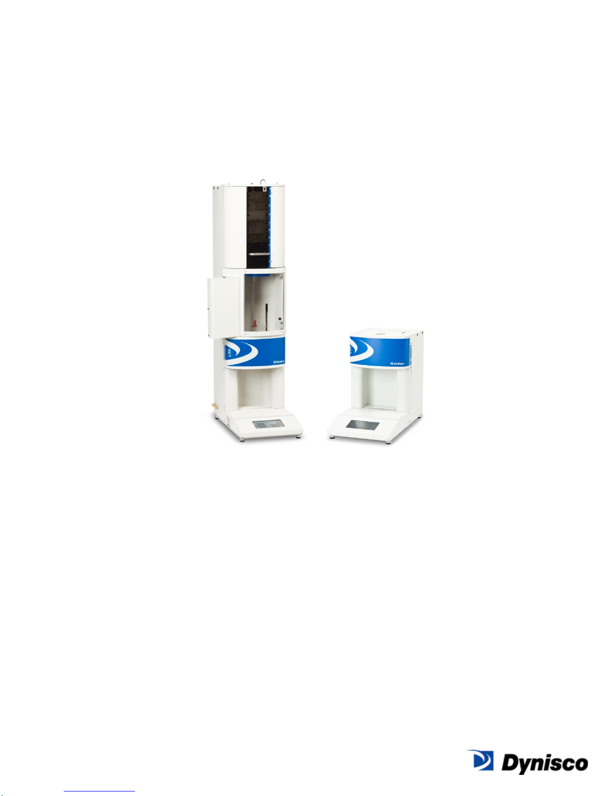
LMFI 5000 Series
Melt Indexer
User’s Guide
Original English Version
Manual Part No. M0726(2)
Page 2

SUPPORT CONTACT INFORMATION
Dynisco Polymer Test can be contacted for questions and support at:
By Phone and Fax:
Phone +1 508 541 9400
Fax +1 508 541 6206
To help us handle your questions as quickly as possible, have the following items ready before
you call:
1. Instrument name and model number (on back panel)
2. Instrument serial number (on back panel)
3. Current version of instrument firmware (Power up unit to see, version shown on “About”
screen under “Maintenance Tab”)
4. Computer system make and model (if applicable)
5. Current version of LaVA Suite software (if applicable)
By Internet:
For Technical and Service Support: http://www.dynisco.com/polytest-services
For all Other Inquiries: http://www.dynisco.com/
By Mail/Post:
38 Forge Parkway
Franklin, MA 02038
M0726(2):LMFI Series 5000 Lab Melt Flow Indexer 2
English 02/2014
Copyright © Dynisco 2012
Page 3
Document
Number
Date
Comments
M0726 (0)
December 2012
Original edition; initial release
M0726 (1)
May 2103
Updated, Product Launch Release
M0726 (2)
Feb 2014
Updated for Versions 1.9 and 2.0
Internal Firmware, Improved Wording
All Rights Reserved
DISCLAIMER OF WARRANTY AND LIABILITY
The information provided herein is believed to be true and correct but no warranty is given as to its
completeness, accuracy or fitness for use for any particular purpose. Dynisco shall not be liable
for any loss or damage arising from the failure to achieve a particular result by the application of
any route, method or process that is recommended herein. Dynisco reserves the right to change
any information, route, method, or process which is discussed or provided herein without notice.
Equipment or products made prior to or subsequent to the publication date of this manual may
have parts, features, options or configurations that are not covered in this manual.
Dynisco represents that to the best of its knowledge neither the products, equipment and systems
supplied by it nor their use for the purpose for which they were supplied nor the use of the
information or recommendation provided herein will infringe a valid patent right of any third party,
but no warranty, express or implied, is given in this respect.
Document History
M0726(2):LMFI Series 5000 Lab Melt Flow Indexer 3
English 02/2014
Page 4

TABLE OF CONTENTS
SAFETY INSTRUCTIONS ..................................................................................................................... 6
Warnings, Danger and Informational Symbols ......................................................................... 6
Safety summary ............................................................................................................................. 7
Use Gloves, it's very HOT! ........................................................................................................... 7
Electrical Hazard ........................................................................................................................... 8
Calibration Thermometers Using Mercury................................................................................. 8
Pinch Points ................................................................................................................................... 9
Fumes From Materials.................................................................................................................. 9
INTRODUCTION .................................................................................................................................. 11
SPECIFICATIONS ................................................................................................................................ 12
INSTRUMENT MAINTENANCE RECOMMENDATIONS .............................................................. 13
Equipment Setup .................................................................................................................................. 14
Unpacking the Indexer................................................................................................................ 14
Bench Requirements and Placement ...................................................................................... 14
Level the Melt Indexer ................................................................................................................ 15
Instrument Overview ............................................................................................................................ 16
Front View .................................................................................................................................... 16
Rear View ..................................................................................................................................... 16
Spares/Consumable Items ........................................................................................................ 17
Instrument Operation/Log-In ............................................................................................................... 18
Instrument Operation/Icons ................................................................................................................. 19
Instrument Operation/Menus............................................................................................................... 20
Instrument Operation/Buttons ............................................................................................................. 21
Instrument Operation/Miscellaneous Touch Areas.......................................................................... 24
Instrument Operation/Panel Overview ............................................................................................... 24
Test Calculations .................................................................................................................................. 25
Calculations: Method A .............................................................................................................. 25
Calculations for the Method A test are: .................................................................................... 25
Calculations: Method A/B ........................................................................................................... 25
Calculations: Method B .............................................................................................................. 26
Calculating PET Intrinsic Viscosity (I.V.) from the Melt Indexer ........................................... 27
M0726(2):LMFI Series 5000 Lab Melt Flow Indexer 4
English 02/2014
Page 5

The Amount of Sample ............................................................................................................... 28
Create/Edit Test Conditions ................................................................................................................ 29
System Configuration ........................................................................................................................... 31
Selecting Multi-select Data .................................................................................................................. 31
Entering Numeric Data ......................................................................................................................... 33
Setting Up a Test .................................................................................................................................. 34
Loading and Packing Material into the Barrel ................................................................................... 35
Running a Test ...................................................................................................................................... 36
Cleaning Up ........................................................................................................................................... 37
TROUBLESHOOTING ......................................................................................................................... 38
Actions .......................................................................................................................................... 38
Generic Run Check List ............................................................................................................. 38
Prior to loading Sample: ............................................................................................................. 38
Long term items: .......................................................................................................................... 39
Support Vendors ......................................................................................................................... 39
M0726(2):LMFI Series 5000 Lab Melt Flow Indexer 5
English 02/2014
Page 6
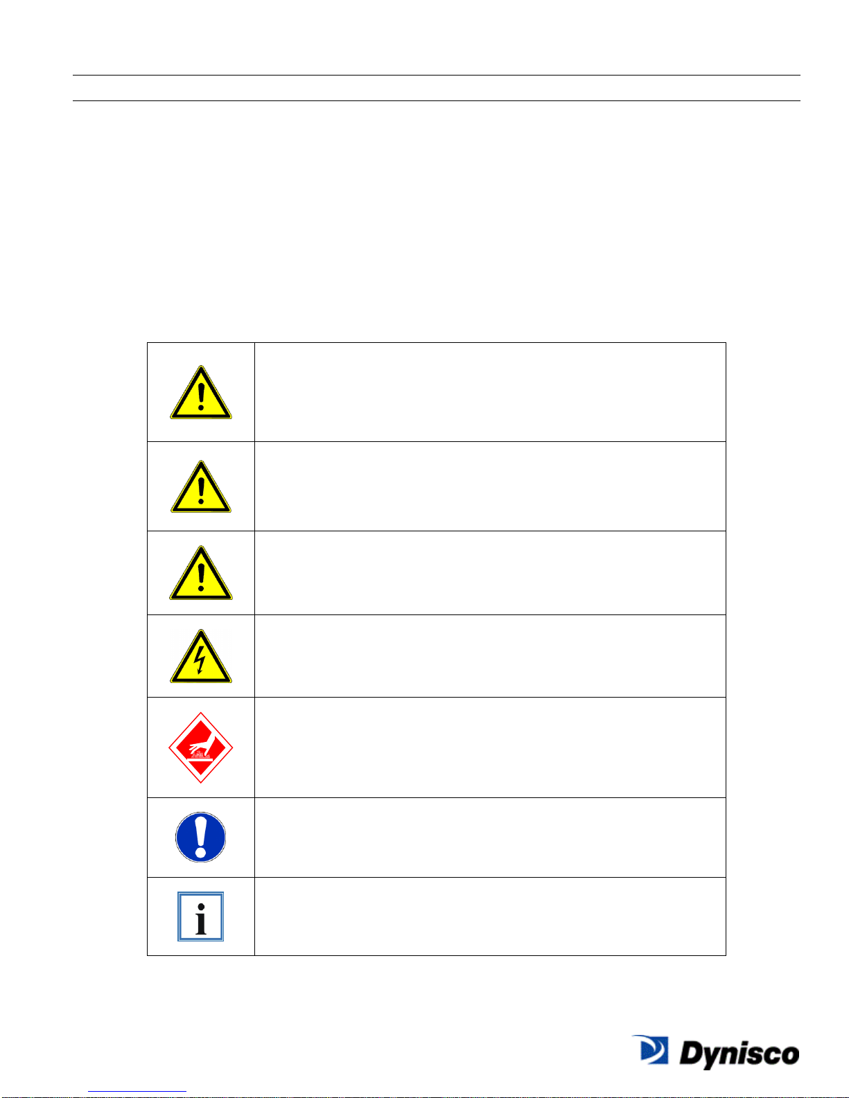
Danger
This symbol indicates that death, serious bodily
injuries or considerable damage to property will
occur if the corresponding safety measures are not
observed!
Warning
This symbol indicates that death, serious bodily
injuries or considerable damage to property may
occur if the corresponding safety measures are not
observed!
Caution
This symbol indicates that minor bodily injuries or
minor damage to property may occur if the
corresponding safety measures are not observed!
This symbol indicates that special danger to the life
and health of persons is present due to electric
potential!
This symbol indicates that special danger to the life
and health of persons is present due to hot surfaces!
This symbol indicates that sufficient personal
protective equipment must be worn when working
with the LMFI. The type of personal protective
equipment will be defined in detail!
This symbol signalises user hints and other special
information, which may be useful. This symbol does
not signalise safety instructions!
SAFETY INSTRUCTIONS
All safety instructions must be understood and observed. Non-observance of safety instructions
may cause damage to life and health of persons, environmental damage and/or extensive
damage to property.
Observing the safety instructions included in the operating instructions will help to avoid dangers,
to operate the product profitably and to secure the full use of the product.
Warnings, Danger and Informational Symbols
General safety instructions concerning the activities are given at the beginning of the relevant
chapter. Special safety instructions concerning the individual steps of action will be given together
with the corresponding step of action.
The following pictographs are used in the present operating instructions
Please also note that a safety symbol may never substitute the text of a safety instruction therefore, the text of a safety instruction must always be read completely!
M0726(2):LMFI Series 5000 Lab Melt Flow Indexer 6
English 02/2014
Page 7
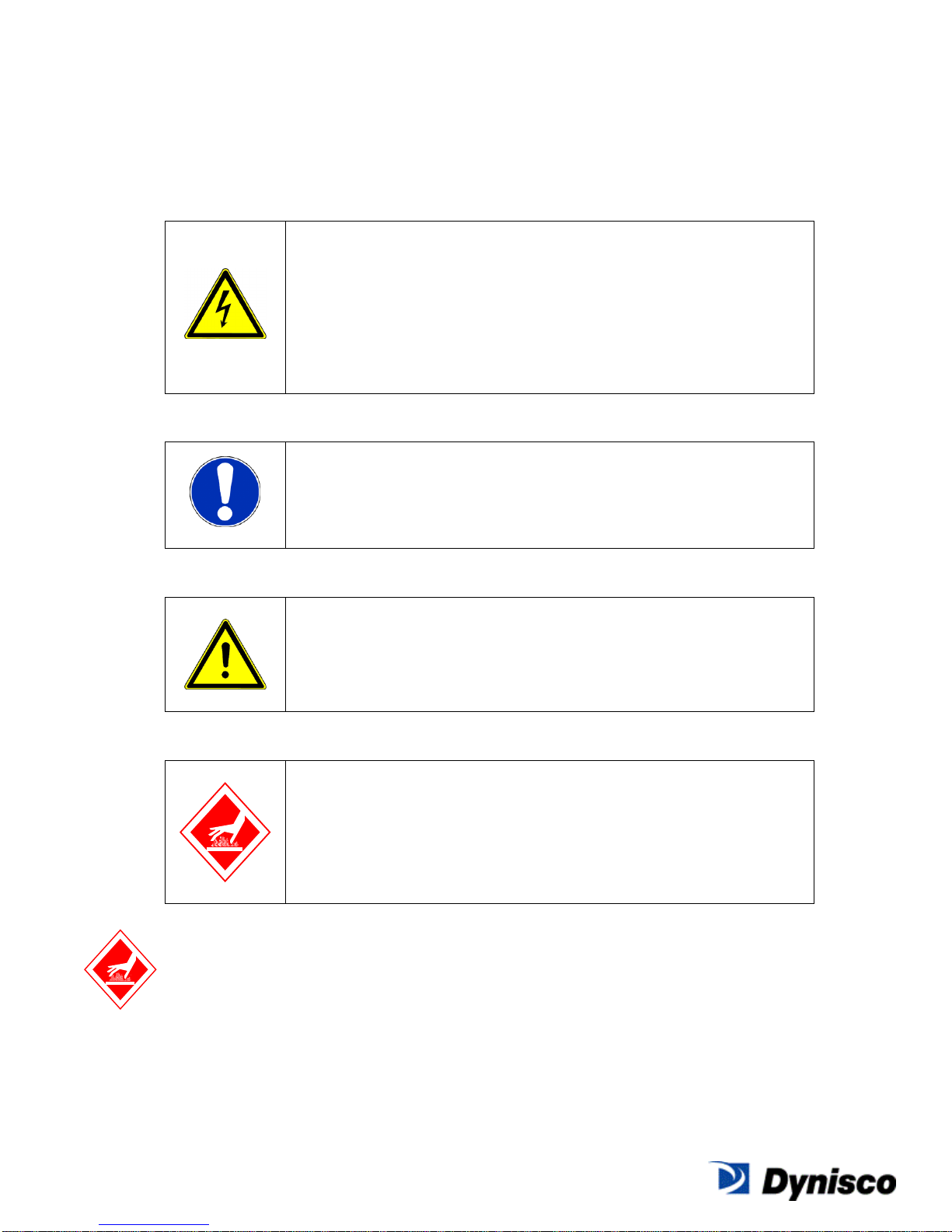
Do not replace components or make adjustments inside
equipment with power turned on. To avoid injuries, always
remove power source and discharge and ground a circuit
before touching it. When making electrical connections, the
services of a qualified electrician must be employed. Contact
with live electrical circuits can cause serious personal injury or
death. Be sure no circuits are energized during installation,
connection or removal of any electrical cables or lines.
Wear protective clothing (gloves, apron, goggles, etc.)
approved for the materials and tools being used.
Warning
Provide ventilation to remove heat and noxious odors and to
prevent the accumulation of asphyxiates such as nitrogen gas.
Keep hands away from hot surfaces and materials. Contact
with hot surfaces or materials can cause blistering and third
degree burns. Wear approved, clean, thermally insulated
gloves when handling these components. Should injury occur;
immerse injured area in cold water and get immediate medical
attention.
Safety summary
The following are recommended safety precautions unrelated to any specific procedures in this
manual and therefore do not appear elsewhere. Personnel must understand and apply them as
appropriate during all phases of operation and maintenance. IN ALL CASES, BE PRUDENT.
Keep away from live circuits
Wear protective clothing
Provide adequate ventilation
Avoid hot surfaces
Use gloves, it's very HOT!
To prevent burns, gloves and a long sleeve shirt (or lab coat) are essential. Dies and piston rods
are extremely hot and are designed to quickly transfer heat to the sample being tested.
Unfortunately this means they will transfer heat very quickly to you as well. Even brief contact
with a hot item can cause a burn. The indexer barrel housing can also get fairly hot. However, at
any barrel temperature, these should not cause burns if touched for a very brief period except
M0726(2):LMFI Series 5000 Lab Melt Flow Indexer 7
English 02/2014
Page 8
very near the barrel top and bottom. Consider where dies may fall. If they are dropped on Nylon
carpeting or similar materials they can quickly form holes. Protective mats may be needed.
DYNISCO POLYMER TEST recommends keeping hot piston rod and hot die in the
chamber/barrel; this precludes someone picking it up inadvertently. Be sure to hold the piston
by the top insulator.
Electrical Hazard
Your Dynisco Lab Melt Flow Indexer contains high voltage inside the housing. DO NOT remove
the housing or any part of its outer covers; there are no user serviceable parts inside. Service
should only be done by a qualified DYNISCO Service Technician. Be sure the outlet used to
power the indexer is properly grounded.
Calibration Thermometers may use Mercury
To calibrate the temperature on the indexer, a thermometer containing about 8 grams of mercury
may be used. Every lab with mercury thermometers or equipment containing mercury must be
prepared for breakage. Note that mercury exposed to air “evaporates” at room temperature,
producing an invisible, tasteless, odorless and dangerous vapor. Thermometers have been used
for decades in laboratory equipment and when used properly provide an accurate and effective
means of calibration. Keep the thermometer in a safe place where it will not be crushed or
otherwise broken. When using the thermometer be careful not to drop or bend the glass. Place
a hot thermometer onto cotton patches to cool. Never put a hot thermometer in contact with cold
metal or cold solvent because the thermal shock can crack or shatter the glass. Mercury is
extremely toxic and should be handled accordingly.
A material safety data sheet (MSDS) for mercury (Hg) can be found on the Internet. Observe
local, state and federal hazardous waste disposal laws when disposing of any broken
thermometers. If packaged in a sealed plastic container and labeled with the following symbol:
Broken thermometers and their spilled mercury can be sent back to the manufacturer.
UPS will accept these packages provided they are labeled and the material is in a secure
container. See Princo support vendor for address information.
M0726(2):LMFI Series 5000 Lab Melt Flow Indexer 8
English 02/2014
Page 9
Pinch Points
Do not place weights in precarious positions where they can be bumped and fall to the floor. For
large test weights (over 10 kg) the pneumatic lift system is recommended. The lift system
has a mechanical capture rod which will not allow the weights to “fall” out of the machine. When
the machine is in operation the lift system moves the weight downward somewhat quickly
creating an area where anything lying beneath could be crushed. The lift system has a safety
door that, when installed correctly and not tampered with, will prevent the lift from moving when
open. There are redundant internal firmware and mechanical hardware safeties in place in the lift
system.
Fumes from Materials
Please plan for unexpected issues to arise. Many polymers (PVC, PVF etc.) are well known for
giving off hazardous fumes at elevated temperatures. An exhaust system that removes fumes
from both the die exit and near the top of the barrel is strongly recommended. Consideration
should also be given to additives that may degrade or decompose at elevated test temperatures.
M0726(2):LMFI Series 5000 Lab Melt Flow Indexer 9
English 02/2014
Page 10

Obligation of the operator to exercise due care
The LMFI was designed and constructed taking into consideration a hazard analysis having
carefully adhering to the harmonised safety standards as well as further technical specifications.
Thus, the LMFI conforms to the state of the art technology and ensures a maximum of safety.
In practical operation, this safety can, however, be achieved only if all necessary measures are
taken. The obligation of the plant operator to exercise due care includes planning these measures
and supervising their execution.
Especially, the operator has to ensure that
• The LMFI will be used only in accordance with the intended purpose.
• The LMFI will be operated in a flawless, functionally efficient condition and that, in particular,
the functional efficiency of the safety devices will be checked at regular intervals.
• No modifications will be made to the component except by a Dynisco service person.
• The necessary personal protective equipment for the operation, maintenance, and service will
be available and used by any personnel performing these functions.
• The operating instructions are always available completely and fully legible at the installation
location of the LMFI. It must be guaranteed that all persons who work with the LMFI can
consult the operating instructions at any time.
• Only sufficiently qualified and authorized personnel will operate, maintain, and repair the LMFI.
• All safety and warning labels, attached to the LMFI, must not be removed and must remain
fully legible.
• Additional instructions, in accordance with facility, local, state and federal industrial safety
regulations and their corresponding, related ordinances for the use of work materials, will have
to be made available as a supplement to the operating instructions.
M0726(2):LMFI Series 5000 Lab Melt Flow Indexer 10
English 02/2014
Page 11
Method A
Method A -- the test is completely manual and is sometimes called
the "cut-and-weigh" method. Measurement in g/10min.
Method A/B
Method A/B -- this employs a digital encoder. In order to run a
method B test, an A/B test MUST be run first to determine the
polymer's melt density. This test takes both A-type and B-type
results to determine melt density. Measurement in g/cc.
Method B
Method B can be conducted only if material melt density is known as
is determined by an A/B type test. This is a "no-cuts" test that is the
most convenient for busy laboratories. Measurement in cc/10min.
Method C
Method C can be conducted only if material melt density is known as
is determined by an A/B type test. This is also known as the “half
die” method. A half-length die is used and is generally used for
testing high flow rate polymers. This is a "no-cuts" test that is the
most convenient for busy laboratories. Measurement in cc/10min.
Method D
Method D can be conducted only if material melt density is known as
is determined by an A/B type test. This is also known as a FRR
(Flow Rate Ratio) test. It uses two weights with the same charge
of material to determine the materials FRR. The FRR is the ratio of
the average flow rate of the material under higher load to the
average flow rate of the material under lower load. This is a "nocuts" test that is the most convenient for busy laboratories.
Measurement is unit-less ratio.
INTRODUCTION
A flow rate test is a measure of a polymer's mass flow rate (grams extruded in 10 minutes) using a
particular orifice under specified conditions of temperature and load. Machines that determine
flow rate are generally called Melt Indexers. Test methods by ISO, DIN, ASTM and others specify
heat chamber and piston tip diameter such that the shear stress on the polymer is the same in all
machines for a given load. In addition, material specification guidelines (by ISO, DIN, ASTM, GM
etc) may exist which give further constraints on how a particular type of material may be run.
The tests performed are those described by ASTM D1238 and ISO 1133-1, 1133-2. This manual
in no way supersedes either of these documents. The precision and accuracy of the test has been
determined by ASTM method D1238. Contributing to both precision and accuracy are operator
variances such as; packing technique, cleaning, cutting, weighing etc. With moisture sensitive
polymers, dryness can also play a major role, and time can be a factor with thermally unstable
polymers, so procedures must be identical. Dynisco Polymer Test Systems has found that
charging a consistent mass of material into the barrel (±0.1 grams) is the most critical factor in
getting precise data.
Several methods have been developed for running flow rate tests under D1238, with Methods A
(mass of material over time) and B (volume of material over time) being the basic of all methods.
Method A is simply the collection of extrudate over time, while Methods B, C and D are the
measurement of time for the flow of a fixed volume of polymer. All but Method A require an
encoder to measure distance traveled to detemine volume of material extruded during the test.
M0726(2):LMFI Series 5000 Lab Melt Flow Indexer 11
English 02/2014
Page 12

Base model
With Lift System (no weights
installed)
Height (in/cm)
20/51
51/132
Width (in/cm)
13/33
13/33
Depth (in/cm)
25/64
25/64
Weight (lb/kg)
47/21.4
100/45.5
SPECIFICATIONS
UTILITIES:
Electrical Requirements: 100-120 VAC / 220-230 VAC, 6A/4A-Peak at Power-up,
5A/2.5A, 500VA-normal operational power, 50 Hz / 60 Hz
PNEUMATICS:
Lift Option (PSI/Bar): MIN: 60/4.2 MAX: 80/5.5
Packer Option (PSI/Bar): MIN: 20/1.4 MAX: 50/3.5
DIMENSIONS:
Instrument with weight system could have up to 70lbs/31.6Kg weights installed (shipped
uninstalled with unit)
OTHER:
Complies with ISO ASTM D1238 and ISO 1133-1, ISO 1133-2.
M0726(2):LMFI Series 5000 Lab Melt Flow Indexer 12
English 02/2014
Page 13

INSTRUMENT MAINTENANCE RECOMMENDATIONS
Daily: Remove the orifice and clean thoroughly with brush and precision drill bit. Clean your
indexer barrel with cotton patches when hot. Piston should spin easily when placed into a
clean barrel.
Weekly: Give good cleaning with brass brush. Use oven cleaner to clean the piston rod
exposed metal and orifice.
Monthly or Long Term: Depending on your company policy, a calibration or calibration check
may be needed on a monthly, quarterly or yearly basis. It is a recommended that a repetitive
maintenance schedule be created for your instrument.
Clean unit: Clean the dust and dirt out of the electronics module with clean air every six
months to one year, more often in dirty environments. Perform this with power removed from
the system. Remove the orifice and clean thoroughly. Clean your barrel. Use oven cleaner to
clean the piston rod assembly and orifice.
Check Mechanical Tolerances: All dimensions and tolerances per ASTM D1238 and ISO
1133-1. Piston tip diameter = 0.3730”/9.474mm +/-0.0003”/0.0076mm; piston tip length =
0.2500”/6.35mm +/- 0.0050”/0.127mm. Assembled piston rod weighs 100 grams. GO/NO-GO
gage works properly on the orifice. Orifice length = 0.3150”/8mm +/- 0.0010”/0.0254mm.
Weights still weigh correctly. Digital Encoder calibration. Gages can be purchased from
Dynisco Polymer Test.
Barrel Diameter: Once the barrel is extremely clean, all dimensional measurements are to be
made at room temperature it can be checked using a bore gage. Gage can be purchased from
Dynisco Polymer Test. At the time of manufacture, the barrel center bore measures
0.3760”/9.55mm +/- 0.0002”/0.00508mm. All dimensions and tolerances per ASTM D1238
and ISO 1133-1.
Pneumatic Lift maintenance: The guide rod and the pneumatic cylinder rod can be
lubricated. Dynisco Polymer Test suggests that WD-40 or machining oil be used as a lubricant.
You can also spray a small amount of WD-40 into the air manifold through the manifold’s air
intake to lubricate all internal parts.
Ask for help: Call Dynisco Polymer Test directly at (508) 541-9400 or visit
http://www.dynisco.com/polytest-services and ask for technical support. To help us handle your
questions as quickly as possible, have the following items ready before you call:
1. Instrument name and model number (on back panel)
2. Instrument serial number (on back panel)
3. Current version of instrument firmware (Power up unit to see, version shown on
“About” screen under “Maintenance Tab”)
4. Computer system make and model (if applicable)
5. Current version of LaVA Suite software (if applicable)
M0726(2):LMFI Series 5000 Lab Melt Flow Indexer 13
English 02/2014
Page 14

Equipment Setup
Unpacking the Indexer
The Lab Melt Flow Indexer comes in a heavy duty, wood container. First, remove the
container’s lid—a bit tool should be within the crate packing documents on the outside of the
container that can be inserted into an electric type drill to remove the lid and bracing screws.
Several boxes may be packed inside along with the instrument; remove them and check that all
boxes are received. For example, they are coded 1 of 5 or 3 of 5, indicating the total number is
five.
For non-weight lift model instruments, the instrument is braced into the box with test weights and
possibly accessories under the instrument in a foam pattern. Remove the instrument’s bracing.
Minding that a base unit weights 45lbs/21.4Kg, either lift the unit out from the top of the
container with two people or carefully lay the container on its side and slide the instrument out of
the container.
For weight lift models, the instrument is braced into the box with test weights and accessories in
separate, internal boxes removed from above step. Noting which side is the bottom of the
instrument and leaving the cross bracing in place, stand crate upward with the bottom of the
instrument downward. Remove the cross bracing and slide the instrument carefully out of the
container onto the floor or a lift. Use a minimum of 3 personnel for this operation for lifting and
stabilizing the instrument as it is being moved. Note the shipping weight of the instrument with
lift is 100lbs/45.45Kg.
It is recommended that the shipping container be saved a few days until you are certain the
machine is functioning as expected.
Bench Requirements and Placement
Typical laboratory benches are too high for efficient use of the indexers. Cleaning and
material packing can be difficult and requires awkward hand positions and forces that could lead
to carpal tunnel syndrome or back discomfort. We strongly suggest a bench height of 29 inches
(desk top height) for an average height operator. Place the front of the indexer flush with the front
edge of the table. This will prevent the operator from having to bend forward excessively when
cleaning and packing the barrel and allow easier access to the back of the machine. As a
minimum, the lab bench should easily be able to support the indexer and operator (total approx.
300lbs/136.36Kg).
DYNISCO POLYMER TEST recommends placing from left to right, if using these options, the melt
indexer; sample scale and computer. Shake test the melt indexer for stability. The bench top
should also be able to withstand hot dies and tools being dropped on them. If carpet is present on
the floor near the LMFI, carpet protection is necessary since a hot die, hot material or hot piston
dropped on the carpet will quickly burn spots in it.
Adequate ventilation will also be required to remove potentially harmful fumes from samples being
tested. Consult the Material Safety Data Sheets (MSDS) on the products to be tested and your
material supplier to assess the magnitude of your ventilation needs. You will want to consider
these ventilation needs when positioning the instrument in the laboratory.
Most of the machine comes pre-assembled to your door. However, certain parts are prone to
breakage if they were placed in their normal operating position during shipping. These items will
need to be installed before safe operation of the machine is possible. Other issues important to
obtaining accurate data must also be addressed before valid testing can begin.
M0726(2):LMFI Series 5000 Lab Melt Flow Indexer 14
English 02/2014
Page 15

Level the Melt Indexer
Using a small round bubble level, level the melt indexer. Place the level on top of the COLD barrel
and using the adjustable screw feet, bring the machine into level. Tighten the locking nuts to keep
the feet in level position Test shake the melt indexer for stability.
Some companies may choose to bolt the machines directly to their benches.
This can be done by removing the levelling feet and using their mounting holes to mount the
instrument to a bench or table. Use caution and remove power before doing so. Mounting this
way will entail removing some covers for internal access to the internal, main instrument plate.
Be sure to remove the level before turning on the machine. The level will be damaged if it gets hot.
M0726(2):LMFI Series 5000 Lab Melt Flow Indexer 15
English 02/2014
Page 16

Power Switch
Power Cord
Packer
Encoder
Lift System
Front View
Instrument Overview
Figure 1: LMFI with lift, encoder and packer Figure2: LMFI base unit
Figure 1 shows LMFI with the lift option; encoder option and packer option.
Figure 2 shows the LMFI base unit that has no options
Rear View
M0726(2):LMFI Series 5000 Lab Melt Flow Indexer 16
English 02/2014
Figure 3: LMFI rear view Power connections
Page 17

Item
Part No.
Qty (Each)
LMFI 5000 Operator’s Manual
M0726
1
Barrel (If wore, out of specification)
4051-25A
1
Piston Assembly (Tip, Piston, Weight Top)
7051-72
1
Piston Tip
0051-41
1
Die/Orifice (Standard 8mm Height)
0051-46
1
Die/Orifice (Half-Die 4mm Height Half
Diameter)
0051-46S
1
Insulator, Top Mica (Die Entry Point)
4051-20MA
1
Barrel Cleaning Patches
GP0104
1 bag (100ea)
Barrel Cleaning Patches
GP0103
1 bag (1000ea)
Die Go/No-Go Gauge
0051-55
1
Die Cleaning Drill
0051-39
1
Barrel Cleaning Brush
B0555
1
Barrel Cleaning Tool (Used with Patches)
0051-40
1
Die Removal Tool
0051-35
1
Funnel, Polymer Charging
0051-80
1
Polymer Packing Hand Tool
0051-36
1
Knife, Palette (For Cutting—Method A)
0051-53
1
USB Cable
Figure 4: LMFI side view USB connections
Figure 3 shows the rear connections of the LMFI. Figure 4 shows the side USB connections with
a PC cable connection to the USB, Type A connection. If using the LaVA Suite software, there is
one cable connection that must be made from the instrument to the computer: a USB cable. The
product sticker on the back of the LMFI will show the model, power requirements and the
instrument serial number.
Spares/Consumable Items
M0726(2):LMFI Series 5000 Lab Melt Flow Indexer 17
English 02/2014
Page 18

User Groups
Default User
Password
Access Rights
GUEST
Viewing only. No programs, system
configuration (except volume and
screen brightness), or calibration can be
modified. Tests cannot be performed.
TESTER
Testing only. Cannot modify programs
that are stored in memory. Can run tests
and change test variables for the current
test in which the values are not saved
into memory. Can modify some of the
system configuration, but cannot run
calibration.
MANAGER
Program Editor. Same rights as “Tester”
plus modifying of programs that are
stored in memory.
ADMIN
ADMIN
ADMIN
System Admin. All rights as “Manager”
plus access to calibration tests.
MAINTENANCE
MAINTENANCE
Maintenance. All rights as “Admin”
plus access to special maintenance
information.
Instrument Operation/Log-In
When the system is powered-up, a log-in screen will appear. Below is a list of default user names
and password and levels of access. The system has 5 levels of default user types. Admin and
Maintenance user levels are defaulted with instruments at shipment. Users of Guest, Tester, and
Manager levels will have to be added by the Admin level user if desired.
Logging-in at power-up can be turned off if not desired. Simply log-in at the Admin level.
Go to System Configuration’s second screen using the and then to get to the
screen. Then simply set User Login to “OFF” as shown here.
M0726(2):LMFI Series 5000 Lab Melt Flow Indexer 18
English 02/2014
Page 19

Icons –An icon will be displayed when a device has been connected to either the master or
host USB connections.
Remote computer is connected
Error during initialization of the remote computer
Mass storage device is connected
Error during initialization of the mass storage
Printer is connected
Error during initialization of the printer
Scale is connected
Error during initialization of the scale
Instrument Operation/Icons
M0726(2):LMFI Series 5000 Lab Melt Flow Indexer 19
English 02/2014
Page 20

Menu Buttons –Menu buttons are a specific type of button that does not have the same attributes
as a normal button. The menu button can be: not selected, selected, or disabled.
The button is only a touch area when in “not selected” mode.
Displays the Test Status Screen
Displays the Programs Screen
Displays the Test Setup Screen
Displays the System
Configuration Screen
Displays the Maintenance Screen
Instrument Operation/Menus
M0726(2):LMFI Series 5000 Lab Melt Flow Indexer 20
English 02/2014
Page 21

Buttons –A button is an active touch area that will perform a specific action
on the release of the button. There are three states to a button: released,
pressed, and disabled along with the option of a press and hold which
will repeat the desired action as long as the button is pressed.
Displays the “About” window .
Sets the screen brightness to
to the maximum level.
Sets the screen brightness to
to the medium high level.
Sets the screen brightness to
to the medium low level.
Sets the screen brightness to
to the minimum level.
Closes the currently active window.
Displays the weight configuration
window.
Continues/Moves Forward the
currently running test.
Copies the currently selected test conditions
from the USB device into the system or
from the system to the USB device.
Deletes the currently selected
test condition.
Instrument Operation/Buttons
M0726(2):LMFI Series 5000 Lab Melt Flow Indexer 21
English 02/2014
Page 22

Displays the test conditions Edit
screen with the currently selected
test conditions.
Stops the currently running test or
stops the series if the system is
running a series.
Displays the lift override/ manual
operation window.
Creates new test conditions and
changes to the test conditions
Edit screen.
Prints a test page to a
connected printer.
Displays the import test
conditions window.
Displays the export test
conditions window.
Displays the test results
export options.
Saves the current information.
Selects all items.
Deselects all items.
M0726(2):LMFI Series 5000 Lab Melt Flow Indexer 22
English 02/2014
Page 23

Buttons Continued
Selects the current test conditions
and displays the test setup screen.
Displays the edit date and
time screen.
Starts a test with the current test
information and displays the test
status screen.
Sets the system volume to the
the maximum level.
Sets the system volume to the
medium level.
Sets the system volume to the
minimum level.
Sets the system volume to off.
Select/ OK button that will accept
the current condition.
Displays the tool tip window.
Logs the user in or displays the
Edit user window.
Displays the RTD calibration window.
Displays the LCD/ Display
Calibration window.
M0726(2):LMFI Series 5000 Lab Melt Flow Indexer 23
English 02/2014
Page 24

Miscellaneous Touch Areas—The following items are touch areas that will perform the specified operation
after the button has been released. There are three states to a button: released,
pressed, and disabled.
Displays the multi-selection screen
with the current value selected.
Displays a number pad or keyboard
based on the selected variable.
Enables or disables the variable. The
center of the button indicates the
current status (enabled or disabled)
Panel Overview
Icons of the devices that are currently
connected to the system.
Press to change the current user that is logged in.
Press to change from
time to date and time.
Menu bar displaying
the currently active
menu. Press on a
menu button to
change to a different
menu.
Instrument Operation/Miscellaneous Touch Areas
Instrument Operation/Panel Overview
M0726(2):LMFI Series 5000 Lab Melt Flow Indexer 24
English 02/2014
Page 25

Test Calculations
Calculations: Method A
Calculations for the Method A test are:
MFR =M 600
T
where M is the mass in grams of material collected over time T in seconds. The MFR value has
units of g/10 min. (grams/10 minutes).
Calculations: Method A/B
In a Method A/B test both a Method A test and Method B test are performed on the same charge
of material. The melt flow rate, derived from Method A, is equated to the Method B flow equation
and solved for apparent melt density. The value in doing this test is obtaining a valid apparent
melt density which can later be used in a Method B test (no manual cuts of extrudate nor
weighing) to achieve results equivalent to Method A (operator must make manual cuts and weigh
sample).
Calculations for the Method A/B test are:
Method B MFR = πR2Lρ 600
TB
Method A MFR = M 600
TA
ρ = MTB
πLR2T
Where R= radius piston (cm), TB (sec) is time to traverse the Method B distance L, L = Method B
length of flag (mm), M is the mass in grams of material collected over the time TA in seconds.
MFR has units of g/10 min. (grams/10 minutes). ρ (g/cc) is called the apparent melt density and is
defined by equating the methods; the Method B flow rate must equal Method A.
This apparent melt density definition forces the two test methods to agree. DYNISCO POLYMER
TEST recommends taking an average of apparent melt densities from at least five separate A/B
tests on representative samples of polymer. This average apparent melt density can then be used
for Method B tests to get Method A (MFR) values without having to make cuts! It is called an
"apparent melt density" because it is actually a correlation coefficient that forces Method A and
Method B to agree. If, during the A/B test, there was no leakage past the plunger tip and the
extrudate was bubble free and other minor factors did not occur, then a true melt density could be
assessed. All lengths are in mm.
M0726(2):LMFI Series 5000 Lab Melt Flow Indexer 25
English 02/2014
Page 26

Temperature(ºC)
LDPE
HDPE
Polybutene-1
polypropylene
120
.797
-
.806
.880
130
.791
-
.800
.872
140
.785
-
.794
.864
150
.780
.780
.787
.852
160
.777
.777
.780
.840
170
.770
.770
.774
.819
180
.765
.765
.767
.758
190
.760
.760
.760
.754
200
.755
.755
.754
.750
210
.748
.748
.746
.746
220
.744
.738
.740
.742
230
.738
.738
.733
.738
240
.733
.733
.726
.734
250
.737
.727
.719
.730
Calculations: Method B
Method B is an assessment of a material's flow characteristics based on the volumetric
displacement rather than weight of extrudate with time as in Method A. Unlike Method A, no
cutting and weighing of the extrudate is required to perform a Method B test. Results from
Method B test can be expressed directly as Melt Volumetric Flow Rate (MVR) in ml/10 min. To
relate the results of a Method B test to Method A, the apparent melt density must be known.
The determination of the apparent density is illustrated in the previous section using Method
A/B. Without the apparent melt density MFR cannot be calculated using Method B. Some
laboratories use MVR directly without ever determining MFR.
The piston’s downward travel time is determined from a counter initiated by a digital encoder.
The encoder senses distance travelled by following the bottom of the test weight(s) which are at
the top of the piston. With all Dynisco Polymer Test Systems flags, Method A and B start in the
same place. Flags may be any length desired and a test can have any number as long as the
total distance of flags is not longer than the distance from the start point and where the piston
would land on the top of the die (≈25.4mm). Recently, Method B has become the more common
test because it is simpler to run (hands free after material load) and more precise for routine
analysis. In addition, the encoder system makes it possible to get more from one run.
Calculations for the Method B test are as follows:
MVRρ = MFR = πR2Lρ 600
T
Where R= radius piston (cm), T (sec) is time to traverse the distance L, L= length of flag (mm), ρ =
apparent melt density of polymer (g/cc).
You should determine the melt densities for your material using your melt indexer. Variations in
technique and difference in material grades can cause differences from user to user. The
following table of melt densities can be used as a general guide if you get values which differ by
more than 10% from these, most likely, something is being done incorrectly. Fillers, reinforcing
agents etc. tend to increase the melt density of the material. Notice that apparent melt density is
a function of temperature. In general the solid state density is a very poor estimate of the
melt density and should not be used.
Some typical Melt Densities
M0726(2):LMFI Series 5000 Lab Melt Flow Indexer 26
English 02/2014
Page 27

MFR
Melt Flow vs.
IV PET Homopolymer
1000
100
10
(g/10min)
1
.30
.40
.50
.60
.70
.80
.90
1.00
1.10
I.V. (dl/g) (OCP 25C)
Any inaccuracies in the melt density will be propagated proportionally along to the MFR
values. Thus a 1% error in the melt density means a 1% accuracy error in the MFR the
value.
Calculating PET Intrinsic Viscosity (I.V.) from the Melt Indexer
This feature allows the Melt Indexer to correlate Melt Flow Rate (g/10 min.) to Intrinsic Viscosity
(dl/g). Intrinsic Viscosity (IV, ASTM D3835) is a "wet chemistry" technique used to assess the
specific volume of an isolated polymer chain, when dissolved in a good solvent. This value is
directly related to the molecular weight of the polymer. Melt viscosity or MFI measurement is
another, empirical (non-absolute like I.V.), way to assess molecular weight. Melt Viscosity and
Intrinsic Viscosity are related in such a way that IV can be directly calculated from Melt Index
values. This is described in greater detail in the applications brief, "Correlating Melt Rheology of
PET to Solution Intrinsic Viscosity" by J. Reilly and P. Limbach, available from DYNISCO
POLYMER TEST on request.
M0726(2):LMFI Series 5000 Lab Melt Flow Indexer 27
English 02/2014
Page 28

Melt Density->
MFR g/10 min
0.75 g/cc
1.0 g/cc
1.2 g/cc
0.1
2.7
3.6
4.4
0.2
2.8
3.7
4.4
0.5
3.0
3.9
4.6 1 3.3
4.2
4.9 2 3.9
4.8
5.5 3 4.5
5.4
6.1 4 5.1
6.0
6.7 5 5.7
6.6
7.3 6 6.3
7.2
7.9 7 6.9
7.8
8.5 8 Plug
8.4
9.1 9 Plug
9.0
9.7
10
Plug
9.6
10.3
11
Plug
Plug
10.9
12
Plug
Plug
11.5
13
Plug
Plug
Plug
The Amount of Sample
ASTM gives a recommendation of how much material to put in the barrel to perform a test.
However, by determining the proper charge and controlling it from run to run. Testing can be
made easier and more reproducible. The distance from the top of the die to the piston’s first
scribe mark is about 5 cm. Filling the barrel up to the first scribe mark is the minimum charge
needed to run a test. During the recommended 6 minute melt time, some material flows out of
the die so a larger charge is needed. The best situation would be to add just enough material,
so that, during the melt time, the plunger slowly falls and is just above the first scribe mark when
the 6 minute melt time has expired. In this way, the required 6 minute melt time is satisfied and
there is no excessive waiting before the first cut is made (or timing flag starts in timed tests). A
conservative estimate for charge weight can be calculated if an approximate melt flow rate and
melt density for the material are known by using the following formula:
Charge Mass = 3.6ρ+0.6*MFR
Where the charge mass is in grams, ρ is the melt density in g/cc and MFR is the anticipated melt
flow rate in the typical units of g/10 min. This equation will tend to slightly overestimate the
charge needed. For a Polypropylene, with an anticipated MFR of 3.5 at 230 C, using the melt
density of 0.738 from the above table, the estimated charge mass would be:
3.6*0.738+0.60*3.5=4.76g
In our lab, we have found that 4.6 grams is a good charge for a 3.5MFR Polypropylene sample.
The equation overestimates the charge since is assumes flow from the instant the material is
packed into the barrel. The following table shows an estimate of charge weight in GRAMS based
on anticipated MFR (g/10 min.) and melt density (g/cc). Where the word “PLUG” appears
indicates you cannot put enough material into the barrel such that after 6 minutes there would be
enough left to test, the barrel must have a flow plug inserted at the base of the die to keep the
material from escaping.
Barrel Charge Size in Grams
M0726(2):LMFI Series 5000 Lab Melt Flow Indexer 28
English 02/2014
Page 29

The page indicator displays the currently selected page
and the total number of pages for the selected screen
Pressing the down button will
display the next set of test
conditions to edit.
Modifies the test conditions
for the desired test.
The page indicator displays the currently selected page
and the total number of pages for the selected screen.
Pressing the down button will
display the next set of test
conditions to edit.
Modifies the test conditions
for the desired test.
Pressing the edit button will display the edit test
conditions screen with the currently selected test conditions.
Select the desired test conditions to edit.
Pressing the new button will display the edit test
conditions screen with a default set of test conditions.
Create/Edit Test Conditions
Create/Edit Test Conditions
English 02/2014
M0726(2):LMFI Series 5000 Lab Melt Flow Indexer 29
Page 30

Press the save button to save the current test conditions. Test conditions are saved based
on program ID so this is value must be unique for each program.
Create/Edit Test Conditions
Continued
M0726(2):LMFI Series 5000 Lab Melt Flow Indexer 30
English 02/2014
Page 31

System Configuration
Press any control to configure the system.
The values are saved on exit from the selected
control window.
Press the volume button to configure the system volume.
The current volume level is displayed as the active button.
Press the test report export options button to display
and configure the options.
Press the brightness button to
set the system brightness. The
current brightness level is
displayed as the active button.
Press the date and time
button to configure the
system date and time
System Configuration
M0726(2):LMFI Series 5000 Lab Melt Flow Indexer 31
English 02/2014
Page 32

By pressing a multi-select control the multi-select window
will be displayed to select the new value.
Pressing the cancel button will return
the window to the previous screen and
retain the old value.
The current selection is highlighted in blue: by pressing any other selection
the window will return to the previous screen and save the selected value.
Selecting Multi-Select Data
Selecting Multi-Select Data
M0726(2):LMFI Series 5000 Lab Melt Flow Indexer 32
English 02/2014
Page 33

Entering Numeric Data
By pressing a numeric control a number pad will
be displayed to enter the new value
Pressing the checkmark will accept
the value that is in the textbox.
Pressing the cancel button the
value will not be saved
The backspace button will delete the last digit that was entered.
Entering Numeric Data
M0726(2):LMFI Series 5000 Lab Melt Flow Indexer 33
English 02/2014
Page 34

Setting up a Test
Select the desired test conditions.
Pressing the select button will load the selected
test conditions and display the test setup screen
Enter a sample ID if desired
Press the start test button
to begin the test.
Setting Up a Test
M0726(2):LMFI Series 5000 Lab Melt Flow Indexer 34
English 02/2014
Page 35

Loading and Packing Material into the Barrel
The piston rod should be inserted into the barrel during heating and temperature stabilization
and between tests. Remove the piston rod and lay on a cotton cloth. Check to see if the die is
at the bottom of the barrel. Fill heat chamber/barrel with an appropriate charge or use about 5
grams if nothing is known about the material. Put the sample into a small beaker. Add about
two-thirds of the material into the barrel, using a fill funnel. The loading should be done in two
increments, the first consisting of approximately two-thirds of the material. Tamp down the
material with the packing tool using approximately 20 pounds/9Kg of force. The packing tool
can be driven through the fill funnel. If bridging (clogging) of the material occurs in the fill
funnel, slide the fill funnel off to one side (without lifting) and use the fill tool to pack the material
in the barrel directly. Move the fill funnel back into place. The remaining material should drop
down into the barrel. Repeat with the remainder of the material.
The Packer Option, if purchased, can be used to tamp down the material. Packer air pressure
is set, depending on material, to achieve the desired packing force. The packer must be
enabled, through the System Configuration screen. Material is loaded, as stated above, with a
funnel. The funnel is removed. The packer is pivoted around and held above the barrel. The
packer’s push button is pressed to extend the packer rod down into barrel. The packer’s push
button is released. The packer rod is released and the entire packer assembly will pivot back to
its starting position. If a lift option is also installed, the lift will not lower if the packer is not back
in its starting position.
Bubbles are present in the test sample charge if a snapping/popping sound is heard as the
extrudate is forced through the orifice. If bubbles appear in the extrudate, use less material
between tamping down. If bubbles continue, the sample may not be sufficiently dry.
Place the piston rod into the barrel by placing the piston rod directly over the slot/opening on the
top of the indexer barrel cover. Seat the guide bushing down into the barrel if it has not already
fallen into place. The guide bushing should be moving freely on the piston plunger. Place the
desired test weight on the piston plunger rod.
The lift option can be used to lower weight onto the piston. The lift must be enabled, through the
System Configuration screen. On the test setup screen, Auto raise, Auto lower and Auto Hold
can be enabled and used for weight sequencing.
M0726(2):LMFI Series 5000 Lab Melt Flow Indexer 35
English 02/2014
Page 36

Running a Test
Summary of the results and series information
Pressing stop will stop the current series. All series
information will be set to default conditions
Pressing the continue Dutton will display the test setup
screen and continue the series. All series information will
be saved for later processing.
Pressing either left of right arrow will navigate to the previous or next screen
Running a Test
To run a test, press the icon from the Test Setup screen after either defining a new test or
selecting a pre-defined test. Follow the screen prompts for temperature stabilization,
packing/loading of material, weight selection and placement, encoder position (if used for test),
and melt time for starting of test.
Once the test has begun, follow the screen prompts for cuts and input of cut weights. After the
test is run, cut weight results can be rejected if desired.
M0726(2):LMFI Series 5000 Lab Melt Flow Indexer 36
English 02/2014
Page 37

Cleaning Up
If using hand weights without the lift system, push down slowly on the weight and purge any
material remaining in the barrel through the die and out of the barrel. If using a weight lift
system, you may want to turn off the “Auto Raise” feature to allow the test weights to dwell at the
end of the test and purge any remaining material from the barrel. Remove the piston rod by
twisting it clockwise to break the seal created by the molten plastic then pull straight up.
Warning: If you pull the rod out too quickly you may cause a suction that pulls the
die out along with the rod which may lead to a very hot die coming off and travelling
through the air or onto the floor or some other undesired location.
While wearing protective gloves, wipe the piston rod with a cotton rag. Remove
the die with the die removal tool. Put two cleaning patches directly over the barrel about 1/2 way
overlapped and, using the cleaning tool, push the patch down into the barrel. Run the patch up
and down a half dozen times or so, and then repeat the process. A minimum of two sets of
patches are generally needed to clean the barrel properly, however, some materials are
harder to clean that others. Repeat the process until used patches come out clean. When the
system is clean, put the die and piston plunger back into the barrel. This allows the piston
plunger and the die to reheat before the next test.
With materials that are thermally stable (less than 5% viscosity change over 1/2
hour of heat exposure) we recommend only cleaning the barrel between every second run or
between changes to different material. For materials that degrade or are moisture sensitive it is
recommend that both the barrel and the die be cleaned completely between each test. To clean
the die, use the die removal rod and push the die up from the bottom of the barrel and out the top.
Wipe it with a cotton rag and clean it by running the drill bit through it several times. Remove
material that collects in the grooves of the drill bit and repeat until the drill passes easily through
the die. Scrape the die with the sample cutting knife if needed to clean the top and bottom faces.
For materials that crystallize quickly you can clean the die by first running a drill bit up into the die
while it is hot and in the indexer. This will make it much easier to get the cleaning drill bit inserted
when the die is removed and the material starts to solidify.
USER TIP: Experienced users often listen for a double bounce of the die when they drop it back
into the barrel to know that the barrel is clean.
Also, while the die is out of the barrel, look down the barrel bore to be sure it is
clean (use safety glasses when looking down the barrel and beware of noxious fumes that may
come from heated material inside!). Ensure the inside surface of the barrel is smooth and shiny
when completely clean.
M0726(2):LMFI Series 5000 Lab Melt Flow Indexer 37
English 02/2014
Page 38

If you don't use gloves, you will eventually get burned. If you are using PVC die
(D3364 for unstable materials), be sure to get the material out of the conical top section.
Standard dies have a flat entrance and exit. When the die is out of the barrel it cools down
quickly. The longer it is out, the longer the wait for the temperature to stabilize will be.
Minimizing the time the die stays out of the machine will increase the number of tests you can
run. When the temperature on the front display is within 0.2 C of the set point, you can begin the
next test. Loading material will cause a small temperature change even if the temperature set
point is locked in. The melt time (360 seconds) will allow ample time to get the temperature to
the set point and stabilize before the first data point is collected.
Always leave the machine clean. If it is going to sit at room temperature for an extended period
of time, you may wish to coat the barrel with a light machine oil to prevent rusting. The oil will
need to be cleaned with cleaning patches from the machine before accurate data can be
obtained.
Warning: Do not heat the barrel back to elevated temperatures before cleaning the
machine oil from the barrel. Noxious fumes and/or fire hazard exists if not cleaned.
TROUBLESHOOTING
Actions
Getting wrong or non-repeatable test values:
Was the instrument clean?
Check density value
Check tip diameter (> 0.3727)
Check Die (clean, diameter length OK?)
Check Machine is Level
Check Temperature
Check weights used +/- 0.5%
Check balance used to weigh extrudate
Piston Rod Bent?
Check die can get to bottom of barrel?
Generic Run Check List
Prior to loading Sample:
Is material properly prepared (dried, mixed, check for contaminates)?
Machine on for 20 minutes to temperature stabilize?
Correct Die in machine?
Correct program being run?
Hand tools in position for run (packing funnel and tool, cleaning drill bit etc.)?
Encoder Arm in place?
M0726(2):LMFI Series 5000 Lab Melt Flow Indexer 38
English 02/2014
Page 39

Long term items:
Are die diameters within spec. (passed G0-No Go gage, ASTM, ISO, DIN)?
Temperature calibration OK?
Piston Tip Diameter within spec.?
Barrel Diameter OK?
Support Vendors
1. NIST Standard Reference Materials (SRM)
For example: Standard Material 1476 is a branched polyethylene with
a MFR of 1.19 ± 0.01. As of 2013, cost was $870/US for 12 grams.
SRM Catalog number is NIST Special Publication 260
To order: (301) 975-6776 Fax (301) 948-3730
2. Mercury (Hg) spill kits
Mercury Clean Up Spill Kits
Mercon Products: distributed by Fisher Scientific
Unit 8, 7551 Vantage Way
Delta, B.C. Canada V4G 1C9
Tech Assistance (800)926-8999
(604) 940-0975 or call Fisher Scientific
3. PRINCO Instruments Inc. (Accepts Standards Hg for Recycle)
1020 Industrial Highway
Southampton, PA 18966
(215) 355-1500
M0726(2):LMFI Series 5000 Lab Melt Flow Indexer 39
English 02/2014
END OF DOCUMENT
 Loading...