

Page 1

OPERATING MANUAL
IPX II SeriesIPX II Series
IPX II SeriesIPX II Series
IPX II Series
SmSm
SmSm
Sm
arar
arar
ar
tt
tt
t
Pr Pr
Pr Pr
Pr
ee
ee
e
ss
ss
s
ss
ss
s
urur
urur
ur
e e
e e
e
TT
TT
T
rr
rr
r
anan
anan
an
smittsmitt
smittsmitt
smitt
erer
erer
er
ss
ss
s
ff
ff
f
or High Pror High Pr
or High Pror High Pr
or High Pr
ee
ee
e
ss
ss
s
ss
ss
s
urur
urur
ur
ee
ee
e
ss
ss
s
and High and High
and High and High
and High
TT
TT
T
emperemper
emperemper
emper
atat
atat
at
urur
urur
ur
ee
ee
e
ss
ss
s
P/N 974100
05/05 Rev. F
ECO # 29918
II 1 GII 1 G
II 1 GII 1 G
II 1 G
AA
AA
A
TEX100aTEX100a
TEX100aTEX100a
TEX100a
Page 2

OPERATING MANUAL
Page 3

OPERATING MANUAL
TT
TT
T
ABLEABLE
ABLEABLE
ABLE
OFOF
OFOF
OF
C C
C C
C
ONTENTSONTENTS
ONTENTSONTENTS
ONTENTS
ContentContent
ContentContent
Content
PP
PP
P
agag
agag
ag
ee
ee
e
IconIcon
IconIcon
Icon
1. General 4
2. Notes on safety 6
3. Technical data 8
4. Function 22
5. Transport/delivery 26
6. Assembly 27
7. Commissioning 34
8. Maintenance 66
9. Accessories 68
10. Troubleshooting 69
11. CE-Declaration of conformity 72
12. Ex-Declaration of conformity 73
Page 4

4
GENERAL
1.1.
1.1.
1.
GG
GG
G
ENERALENERAL
ENERALENERAL
ENERAL
1 . 1 Important information .......................................................................................................... 4
1.2 Copyright ............................................................................................................................. 4
1.3 Explanation of icons ............................................................................................................ 5
1.4 Abbreviations....................................................................................................................... 5
1.5 Correct use .......................................................................................................................... 5
1.6 User’s obligations ................................................................................................................. 5
1.11.1
1.11.1
1.1
II
II
I
MPORMPOR
MPORMPOR
MPOR
TT
TT
T
ANTANT
ANTANT
ANT
INFORMAINFORMA
INFORMAINFORMA
INFORMA
TIONTION
TIONTION
TION
This manual applies to the IPX II series only. It must be kept near the equipment in a readily and
immediately accessible location at all times.
The content of this manual must be read, understood and followed in all points by all relevant
people. This applies in particular to the notes on safety. Following the safety instructions will help to
prevent accidents, defects and malfunctions.
DD
DD
D
YNISCYNISC
YNISCYNISC
YNISC
OO
OO
O will not be held liable for any injury, loss or damage resulting from failure to follow the
instructions in this manual.
If malfunctions occur in spite of having followed the operating instructions, please contact the
DD
DD
D
YNISCYNISC
YNISCYNISC
YNISC
OO
OO
O customer service department (see chapter 8, Maintenance).
This applies in particular during the warranty period.
1.21.2
1.21.2
1.2
CC
CC
C
OPYRIGHTOPYRIGHT
OPYRIGHTOPYRIGHT
OPYRIGHT
Copyright law requires that this manual be used for in-house purposes only.
All reproduction, even partially and for in-house purposes, requires the approval of
DD
DD
D
YNISCYNISC
YNISCYNISC
YNISC
OO
OO
O. This
manual may not be forwarded to third parties.
Rosemount and Smart Family are registered trademarks of Rosemount, Inc.
Hart is a registered trademark of Hart Comunication Foundation.
Page 5

5
GENERAL
1.31.3
1.31.3
1.3
EE
EE
E
XPLANAXPLANA
XPLANAXPLANA
XPLANA
TIONTION
TIONTION
TION
OFOF
OFOF
OF
ICIC
ICIC
IC
ONSONS
ONSONS
ONS
The manual uses icons to indicate information pertaining to safety:
Risk of destruction or damage to equipment, machines or installations
General danger to life or limb
Specific danger to life or limb
You MUST do this
The safety instructions are provided again in the individual chapters of the manual.
1.41.4
1.41.4
1.4
AA
AA
A
BBREVIABBREVIA
BBREVIABBREVIA
BBREVIA
TIONSTIONS
TIONSTIONS
TIONS
The following abbreviations are used:
OMOM
OMOM
O M Operating manual
IPXIPX
IPXIPX
IPX Intelligent pressure transmitter
f.s.f.s.
f.s.f.s.
f.s. of full scale
PTPT
PTPT
P T pressure transmitter
1.51.5
1.51.5
1.5
CC
CC
C
ORRECTORRECT
ORRECTORRECT
ORRECT
USEUSE
USEUSE
USE
The IPX II pressure transmitter is specially designed for measuring pressure in explosive atmospheres
(safety class, EEx ia IIC T4, Ta=-20°C to +80°C) as part of a larger overall system. It contains an
integrated signal amplifier. The IPX II can be used in media temperatures up to 350°C. If the pressure
transmitter is used in other applications, the safety and accident prevention regulations specific to
that application must be followed.
When uWhen u
When uWhen u
When u
ss
ss
s
inin
inin
in
g the IPXg the IPX
g the IPXg the IPX
g the IPX
II a II a
II a II a
II a
ss
ss
s
a s a s
a s a s
a s
afaf
afaf
af
etyety
etyety
ety
c c
c c
c
omponentomponent
omponentomponent
omponent
in ac in ac
in ac in ac
in ac
cc
cc
c
oror
oror
or
dd
dd
d
ancanc
ancanc
anc
e we w
e we w
e w
ith the Eith the E
ith the Eith the E
ith the E
CC
CC
C
M M
M M
M
acac
acac
ac
hine Dirhine Dir
hine Dirhine Dir
hine Dir
ectivectiv
ectivectiv
ectiv
e, Annee, Anne
e, Annee, Anne
e, Anne
xx
xx
x
IIc, the equipmentIIc, the equipment
IIc, the equipmentIIc, the equipment
IIc, the equipment
m m
m m
m
anufanuf
anufanuf
anuf
actact
actact
act
urur
urur
ur
er muer mu
er muer mu
er mu
ss
ss
s
tt
tt
t
t t
t t
t
akak
akak
ak
e ane an
e ane an
e an
yy
yy
y
nec nec
nec nec
nec
ee
ee
e
ss
ss
s
ss
ss
s
arar
arar
ar
yy
yy
y
pr pr
pr pr
pr
ecec
ecec
ec
autionaution
autionaution
aution
ss
ss
s
t t
t t
t
o eno en
o eno en
o en
ss
ss
s
urur
urur
ur
e the th
e the th
e th
atat
atat
at
m m
m m
m
alfalf
alfalf
alf
uu
uu
u
nctionnction
nctionnction
nction
ss
ss
s
ofof
ofof
of
the P the P
the P the P
the P
TT
TT
T
cc
cc
c
annotannot
annotannot
annot
c c
c c
c
auau
auau
au
se dse d
se dse d
se d
amam
amam
am
agag
agag
ag
e or injure or injur
e or injure or injur
e or injur
yy
yy
y
..
..
.
The IPX II is also designed for explosion proof areas approved by factory mutual for Class I, Division
1, Groups B, C & D, Class II/III, Division 2, Group E, F & G.
1.61.6
1.61.6
1.6
UU
UU
U
SS
SS
S
ERER
ERER
ER
’’
’’
’
SS
SS
S
OBLIGAOBLIGA
OBLIGAOBLIGA
OBLIGA
TIONSTIONS
TIONSTIONS
TIONS
The operator or owner of the larger overall system, e.g. a machine, is responsible for following the
safety and accident prevention regulations that apply to the specific application.
Page 6

6
SAFETY
2.2.
2.2.
2.
NN
NN
N
OTESOTES
OTESOTES
OTES
ONON
ONON
ON
SAFETYSAFETY
SAFETYSAFETY
SAFETY
The operator or owner of the larger overall system is responsible for following the safety
and accident prevention regulations that apply to the specific application.
TT
TT
T
oo
oo
o
xx
xx
x
icic
icic
ic
h h
h h
h
azaz
azaz
az
arar
arar
ar
d!d!
d!d!
d!
The IPX II contains a small amount of mercury (Hg) as its transmission medium. If the
diaphragm is damaged, mercury may escape.
Never transport or store the IPX II without the protective cap. Remove the cap shortly
before installation.
IfIf
IfIf
If
mer mer
mer mer
mer
cc
cc
c
urur
urur
ur
yy
yy
y
i i
i i
i
ss
ss
s
inh inh
inh inh
inh
alal
alal
al
ed or swed or sw
ed or swed or sw
ed or sw
alal
alal
al
lolo
lolo
lo
ww
ww
w
ed, seeked, seek
ed, seeked, seek
ed, seek
medic medic
medic medic
medic
alal
alal
al
att att
att att
att
ention immediention immedi
ention immediention immedi
ention immedi
atat
atat
at
ely!ely!
ely!ely!
ely!
Mercury is hazardous waste and must be disposed of in accordance with applicable
laws.
DD
DD
D
YNISCYNISC
YNISCYNISC
YNISC
OO
OO
O will accept defective PTs.
If mercury escapes, use airtight packaging!
When planning machinery and using the IPX II, follow the safety and accident
prevention regulations that apply to your application, e.g.:
• EN 60204, Electrical equipment in machines.
• EN 292, Machine safety, general design guidelines.
• DIN 57 100 Part 410, Protection against electric shock.
• EN 50 014:1997, General Requirements
• EN 50 020:1994, Intrinsic safety apparatus
• EN50284:1999, Speical requirements for Group II Category 1G
Mounting and electrical connection of the PT must be done by specialists with EMC training,
following all applicable regulations, and in
pressureless, voltage-free, intrinsically safepressureless, voltage-free, intrinsically safe
pressureless, voltage-free, intrinsically safepressureless, voltage-free, intrinsically safe
pressureless, voltage-free, intrinsically safe
condition with the
machine switched offmachine switched off
machine switched offmachine switched off
machine switched off.
The mThe m
The mThe m
The m
acac
acac
ac
hine muhine mu
hine muhine mu
hine mu
ss
ss
s
tt
tt
t
be sec be sec
be sec be sec
be sec
urur
urur
ur
ed aged ag
ed aged ag
ed ag
ainain
ainain
ain
ss
ss
s
tt
tt
t
bein bein
bein bein
bein
g swg sw
g swg sw
g sw
itit
itit
it
cc
cc
c
hed bhed b
hed bhed b
hed b
acac
acac
ac
kk
kk
k
on! on!
on! on!
on!
Ambient temperature for the electronics housing
mm
mm
m
ax. +80°Cax. +80°C
ax. +80°Cax. +80°C
ax. +80°C (safety class T4 max.).
Higher temperatures can result in damage and malfunction. Do not install the pressure
transmitter in places where this temperature is exceeded.
ExpExp
ExpExp
Exp
lolo
lolo
lo
ss
ss
s
ion hion h
ion hion h
ion h
azaz
azaz
az
arar
arar
ar
d!d!
d!d!
d!
Deviation of the supply voltage from the value given in the technical specifications, or
false polarity, can damage the pressure transmitter and cause malfunctions that can
pose a risk of explosion.
Page 7

7
SAFETY
Operate only with an intrinsically safe, EMC compliant power supply with the following
specifications when employing the pressure 4-20mA output:
Supply voltage max. 30 V DC
Current output max. 125 mA
Power output max. 900 mW
Inductivity max. 0.26 mH
Capacity max. 9.7 nF
Operate only with an intrinsically safe, EMC compliant power supply with the following
specifications when employing the temperature 4-20mA output:
Supply voltage max. 30 V DC
Current output max. 125 mA
Power output max. 900 mW
Inductivity max. 0 mH
Capacity max. 52 nF
For PT that are explosion proof Class I, Division 1, Groups B, C & D, Class II/III, Division
2, Groups E, F and G. Power supply rating is 12-42 Vdc.
ExpExp
ExpExp
Exp
lolo
lolo
lo
ss
ss
s
ion hion h
ion hion h
ion h
azaz
azaz
az
arar
arar
ar
d!d!
d!d!
d!
The pressure transmitter must be connected using a 2x2-core, twisted cable (blue cable
sheath).
Do not lay connecting cables in the direct vicinity of cables carrying higher voltage orDo not lay connecting cables in the direct vicinity of cables carrying higher voltage or
Do not lay connecting cables in the direct vicinity of cables carrying higher voltage orDo not lay connecting cables in the direct vicinity of cables carrying higher voltage or
Do not lay connecting cables in the direct vicinity of cables carrying higher voltage or
used to switch inductive or capacitive loads.used to switch inductive or capacitive loads.
used to switch inductive or capacitive loads.used to switch inductive or capacitive loads.
used to switch inductive or capacitive loads.
Page 8

8
TECHNICAL DATA
3.3.
3.3.
3.
TT
TT
T
EE
EE
E
CHNICALCHNICAL
CHNICALCHNICAL
CHNICAL
D D
D D
D
AA
AA
A
TT
TT
T
AA
AA
A
3.1 Ordering guide .................................................................................................................... 8
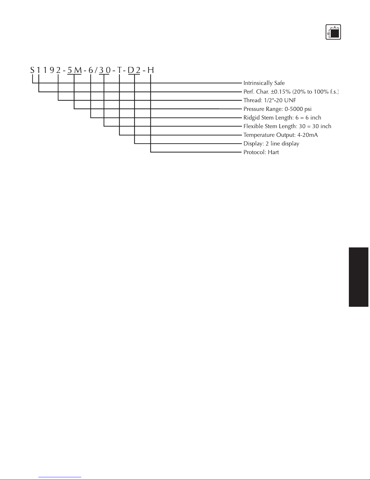
3.2 Ordering example ................................................................................................................ 9
3.3 Safety related specifications ................................................................................................. 9
3.4 Performance characteristics ................................................................................................. 9
3.4.1 Accuracy ............................................................................................................................. 9
3.4.2 Resolution.......................................................................................................................... 1 0
3.5 Pressure side connection ................................................................................................... 1 1
3.6 Pressure ranges .................................................................................................................. 1 1
3.6.1 Pressure ranges in bar ........................................................................................................ 1 1
3.6.2 Max. Overload .................................................................................................................. 1 1
3.6.3 Burst pressure .................................................................................................................... 1 1
3.6.4 Natural frequency .............................................................................................................. 1 1
3.7 Rigid stem/flexible stem .....................................................................................................11
3.8 Electrical Data ................................................................................................................... 1 1
3.9 Temperature influence ....................................................................................................... 12
3.10 EMC requirements ............................................................................................................. 1 2
3.11 Materials............................................................................................................................ 1 3
3.12 Mounting torque ................................................................................................................ 13
3.13 Environmental Protection ................................................................................................... 13
3.14 Weight ............................................................................................................................... 13
3.15 Dimensions ........................................................................................................................ 1 3
3.13.1
3.13.1
3.1
OO
OO
O
RDERINGRDERING
RDERINGRDERING
RDERING
GUIDEGUIDE
GUIDEGUIDE
GUIDE
The exact meanings of the letter/digit combinations are given in the corresponding sections of
chapter 3.
Page 9
9
TECHNICAL DATA
3.23.2
3.23.2
3.2
EE
EE
E
XAMPLEXAMPLE
XAMPLEXAMPLE
XAMPLE
FORFOR
FORFOR
FOR
ORDERINGORDERING
ORDERINGORDERING
ORDERING
3.33.3
3.33.3
3.3
SS
SS
S
AFETAFET
AFETAFET
AFET
YY
YY
Y
RELARELA
RELARELA
RELA
TEDTED
TEDTED
TED
SS
SS
S
PEPE
PEPE
PE
CIFICACIFICA
CIFICACIFICA
CIFICA
TIONSTIONS
TIONSTIONS
TIONS
ATEX certificate No.: SIRA 02ATEX2244X
EX-Safety class EEx ia IIC T4 (Ta = -20°C to +80°C)
FM approvals Class I, Division 1 Groups B, C & D
Class II / III, Division 2 Groups E, F & G
CC
CC
C
erer
erer
er
tified mtified m
tified mtified m
tified m
axax
axax
ax
imum imum
imum imum
imum
vv
vv
v
aluealue
aluealue
alue
ss
ss
s
f f
f f
f
or EExor EEx
or EExor EEx
or EEx
i i
i i
i
a IICa IIC
a IICa IIC
a IIC
T4T4
T4T4
T4
Associated electrical equipment must satisfy the following conditions:
PrPr
PrPr
Pr
ee
ee
e
ss
ss
s
ss
ss
s
urur
urur
ur
e:e:
e:e:
e:
Supply voltage max. 30 V DC
Current output max. 125 mA
Power output max. 900 mW
Inductivity max. 0.26 mH
Capacity max. 9.7 nF
TT
TT
T
emperemper
emperemper
emper
atat
atat
at
urur
urur
ur
e:e:
e:e:
e:
Supply voltage 30 V DC
Current output max. 125 mA
Power output max. 900 mW
Inductivity max. 0 mH
Capacity max. 52 nF
3.43.4
3.43.4
3.4
PP
PP
P
ERFORMANCERFORMANC
ERFORMANCERFORMANC
ERFORMANC
EE
EE
E
CHARACHARA
CHARACHARA
CHARA
CTERISCTERIS
CTERISCTERIS
CTERIS
TICTIC
TICTIC
TIC
SS
SS
S
xx19xx - xx - x - xx - xx / xx - x - x - x - @xxx - xxxx
3.4.13.4.1
3.4.13.4.1
3.4.1
AA
AA
A
CC
CC
C
CC
CC
C
URAURA
URAURA
URA
CYCY
CYCY
CY
(Linearity and repeatability)
Page 10

10
TECHNICAL DATA
3.4.13.4.1
3.4.13.4.1
3.4.1
AA
AA
A
XX
XX
X
11921192
11921192
1192
XX
XX
X
, ,
, ,
,
XX
XX
X
11941194
11941194
1194
XX
XX
X
±0.15% (20% to 100% f.s.)
±0.25% (0% to 20% f.s.)
(0-3000 psi and above)
±0.25% (20% to 100% f.s.)
±0.50% (0% to 20% f.s.)
(0-1500 psi)
3.4.13.4.1
3.4.13.4.1
3.4.1
BB
BB
B
X1193X, X1193X,
X1193X, X1193X,
X1193X,
XX
XX
X
11951195
11951195
1195
XX
XX
X
±0.15% (20% to 100% f.s.)
±0.25% (0% to 20% f.s.)
(0-1500 psi and above)
±0.25% (20% to 100% f.s.)
±0.50% (0% to 20% f.s.)
(0-750 psi)
3.4.13.4.1
3.4.13.4.1
3.4.1
CC
CC
C
XX
XX
X
21922192
21922192
2192
XX
XX
X
, ,
, ,
,
XX
XX
X
21942194
21942194
2194
XX
XX
X
±0.25% (20% to 100% f.s.)
±0.50% (0% to 20% f.s.)
(0-3000 psi and above)
±0.50% (20% to 100% f.s.)
±1.00% (0% to 20% f.s.)
(0-1500 psi)
3.4.13.4.1
3.4.13.4.1
3.4.1
DD
DD
D
X2193X, X2193X,
X2193X, X2193X,
X2193X,
XX
XX
X
21952195
21952195
2195
XX
XX
X
±0.25% (20% to 100% f.s.)
±0.50% (0% to 20% f.s.)
(0-1500 psi and above)
±0.50% (20% to 100% f.s.)
±1.00% (0% to 20% f.s.)
(0.750 psi and above)
3.4.23.4.2
3.4.23.4.2
3.4.2
RR
RR
R
ESOLUTIONESOLUTION
ESOLUTIONESOLUTION
ESOLUTION
0.035% f.s. or better
Page 11

11
TECHNICAL DATA
3.3.
3.3.
3.
55
55
5
PP
PP
P
RERE
RERE
RE
SS
SS
S
SURESURE
SURESURE
SURE
SIDESIDE
SIDESIDE
SIDE
CC
CC
C
ONNEONNE
ONNEONNE
ONNE
CTIONCTION
CTIONCTION
CTION
2 = 1/2" 20 UNF 2A (xx192x-x . . . )
3 = M18 x 1.5 (xx193x-x . . .)
4 or 5 = flange (xx194x-x . . . ) or (xx195x-x . . . )
3.63.6
3.63.6
3.6
PP
PP
P
RESSURERESSURE
RESSURERESSURE
RESSURE
RANGESRANGES
RANGESRANGES
RANGES
( (
( (
(
XXXX
XXXX
XX
1919
1919
19
XXXX
XXXX
XX
))
))
)
3.6.13.6.1
3.6.13.6.1
3.6.1
PP
PP
P
RESSURERESSURE
RESSURERESSURE
RESSURE
RANGESRANGES
RANGESRANGES
RANGES
ININ
ININ
IN
PSIPSI
PSIPSI
PSI
Model numberModel number
Model numberModel number
Model number
PP
PP
P
ermittermitt
ermittermitt
ermitt
ed pred pr
ed pred pr
ed pr
ee
ee
e
ss
ss
s
ss
ss
s
urur
urur
ur
e re r
e re r
e r
anan
anan
an
gg
gg
g
e in Pe in P
e in Pe in P
e in P
SISI
SISI
SI
xx19xx-xx-x-7.5c-x 0-750
(xx193xx & xx195xx only)(xx193xx & xx195xx only)
(xx193xx & xx195xx only)(xx193xx & xx195xx only)
(xx193xx & xx195xx only)
xx19xx-xx-x-1.5c-xm 0-1500
xx19xx-xx-x-3c-xm 0-3000
xx19xx-xx-x-5c-xm 0-5000
xx19xx-xx-x-7.5c-xm 0-7500
xx19xx-xx-x-10c-xm 0-10000
3.6.23.6.2
3.6.23.6.2
3.6.2
MM
MM
M
AXAX
AXAX
AX
. O. O
. O. O
. O
VERLVERL
VERLVERL
VERL
OO
OO
O
ADAD
ADAD
AD
( (
( (
(
WITHOUTWITHOUT
WITHOUTWITHOUT
WITHOUT
INFLINFL
INFLINFL
INFL
UENCINGUENCING
UENCINGUENCING
UENCING
OPERAOPERA
OPERAOPERA
OPERA
TINGTING
TINGTING
TING
DD
DD
D
AA
AA
A
TT
TT
T
AA
AA
A
))
))
)
xx19xx 1.5 x full scale pressure up to 10,000 psi
3.6.33.6.3
3.6.33.6.3
3.6.3
BB
BB
B
URSTURST
URSTURST
URST
PRESSUREPRESSURE
PRESSUREPRESSURE
PRESSURE
3 x nominal value, max. 30,000 psi
3.6.43.6.4
3.6.43.6.4
3.6.4
NN
NN
N
AA
AA
A
TURALTURAL
TURALTURAL
TURAL
FREFRE
FREFRE
FRE
QUENCYQUENCY
QUENCYQUENCY
QUENCY
50 Hz [-3db]
3.73.7
3.73.7
3.7
RR
RR
R
IGIDIGID
IGIDIGID
IGID
STEMSTEM
STEMSTEM
STEM
//
//
/
FLEXIBLEFLEXIBLE
FLEXIBLEFLEXIBLE
FLEXIBLE
STEMSTEM
STEMSTEM
STEM
( (
( (
(
XXXX
XXXX
XX
1919
1919
19
XXXX
XXXX
XX
-)-)
-)-)
-)
6 = 152 mm standard length for rigid version
6/18 = 152 mm stem length / 457 mm flexible stem
Other lengths on request
3.83.8
3.83.8
3.8
EE
EE
E
LELE
LELE
LE
CTRICALCTRICAL
CTRICALCTRICAL
CTRICAL
DD
DD
D
AA
AA
A
TT
TT
T
AA
AA
A
Configuration 4-arm Wheatstone bridge strain gauge with int. amplifier
Output signal 2-wire 4 - 20 mA, optional 2nd 2-wire 4 - 20 mA
Page 12

12
TECHNICAL DATA
Supply voltage 12-30 VDC for EEx ia IIC T4 12-42 for FM approved explosion proof
models
Power consumption -20 mA
Zero balance (xx192x and xx194x)
0.25% for 3000 psi and above
0.5% for 1500 psi
(xx193x and xx195x)
0.25% for 1500 psi and above
0.5% for 750 psi
3.93.9
3.93.9
3.9
TT
TT
T
EMPERAEMPERA
EMPERAEMPERA
EMPERA
TURETURE
TURETURE
TURE
INFLINFL
INFLINFL
INFL
UENCUENC
UENCUENC
UENC
EE
EE
E
ElEl
ElEl
El
ectrectr
ectrectr
ectr
oniconic
oniconic
onic
ss
ss
s
hou hou
hou hou
hou
ss
ss
s
inin
inin
in
gg
gg
g
Max. housing temperatures
Safety class T4 -20°C to +80°C
Compenstated +25°C to +300°C (option to 350°C) - snout
temperature range +25°C to +80°C - electronics
Zero and sensitivity shift due to temperature change on electronics housing
xx19xx ±0.15% f.s./55°C
DiDi
DiDi
Di
aphraphr
aphraphr
aphr
agm (in cagm (in c
agm (in cagm (in c
agm (in c
ontont
ontont
ont
actact
actact
act
w w
w w
w
ith mediith medi
ith mediith medi
ith medi
a)a)
a)a)
a)
Maximum temperature at the diaphragm
xx19xx 350°C
Zero shift due to temperature change on the diaphragm
xx19xx ±0.01 psi / 100°C
3.103.10
3.103.10
3.10
EMCEMC
EMCEMC
EMC
RERE
RERE
RE
QUIREMENTQUIREMENT
QUIREMENTQUIREMENT
QUIREMENT
SS
SS
S
Conforming to CE in accordance with EMC directive.
Electromagnetic Interference DIN EN 550223 1995
Immunity DIN EN 61000-4-2 1995
Radiated, Radio Freq, etc. DIN EN 61000-4-3 1995 +A1:1998+A2:2000
Pulse Magnetic Field DIN EN 61000-4-9 1993 + A1:2001
Page 13

13
TECHNICAL DATA
Surge Immunity DIN EN 61000-4-5 1995 + A1:2000
Conducted Disturbences DIN EN 61000-4-6 1996 + A1:2000
Power Frequency Magnetic Field DIN EN 61000-4-8 1993 + A1:2001
3.113.11
3.113.11
3.11
MM
MM
M
AA
AA
A
TERIALSTERIALS
TERIALSTERIALS
TERIALS
Diaphragm 15-5PH Mat. No. 1.4545 DyMax™ coated
Stem 17-4PH Mat. No. 517400
3.123.12
3.123.12
3.12
TT
TT
T
ORQUEORQUE
ORQUEORQUE
ORQUE
xx192x xx193x xx194x xx195x
max. 56.5 Nm max. 56.5 Nm max. 5.6 Nm max. 14.1 Nm
(500 inch-lbs.) (500 inch-lbs.) (50 inch-lbs.) (125 inch-lbs.)
min. 11.3 Nm min. 11.3 Nm min. 4.5 Nm min. 11.3 Nm
(100 inch-lbs.) (100 inch-lbs.) (40 inch-lbs.) (100 inch-lbs.)
3.133.13
3.133.13
3.13
EE
EE
E
NVIRONMENTNVIRONMENT
NVIRONMENTNVIRONMENT
NVIRONMENT
ALAL
ALAL
AL
PROPRO
PROPRO
PRO
TETE
TETE
TE
CTIONCTION
CTIONCTION
CTION
TT
TT
T
OO
OO
O
IE IE
IE IE
IE
CC
CC
C
5 5
5 5
5
22
22
2
99
99
9
Electronics housing min. IP66, nema 4x
3.143.14
3.143.14
3.14
WW
WW
W
EIGHTEIGHT
EIGHTEIGHT
EIGHT
5-10 lbs.
3.153.15
3.153.15
3.15
DD
DD
D
IMENSIONSIMENSIONS
IMENSIONSIMENSIONS
IMENSIONS
Page 14
14
TECHNICAL DATA
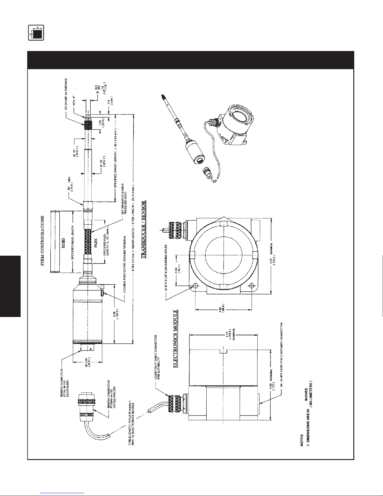
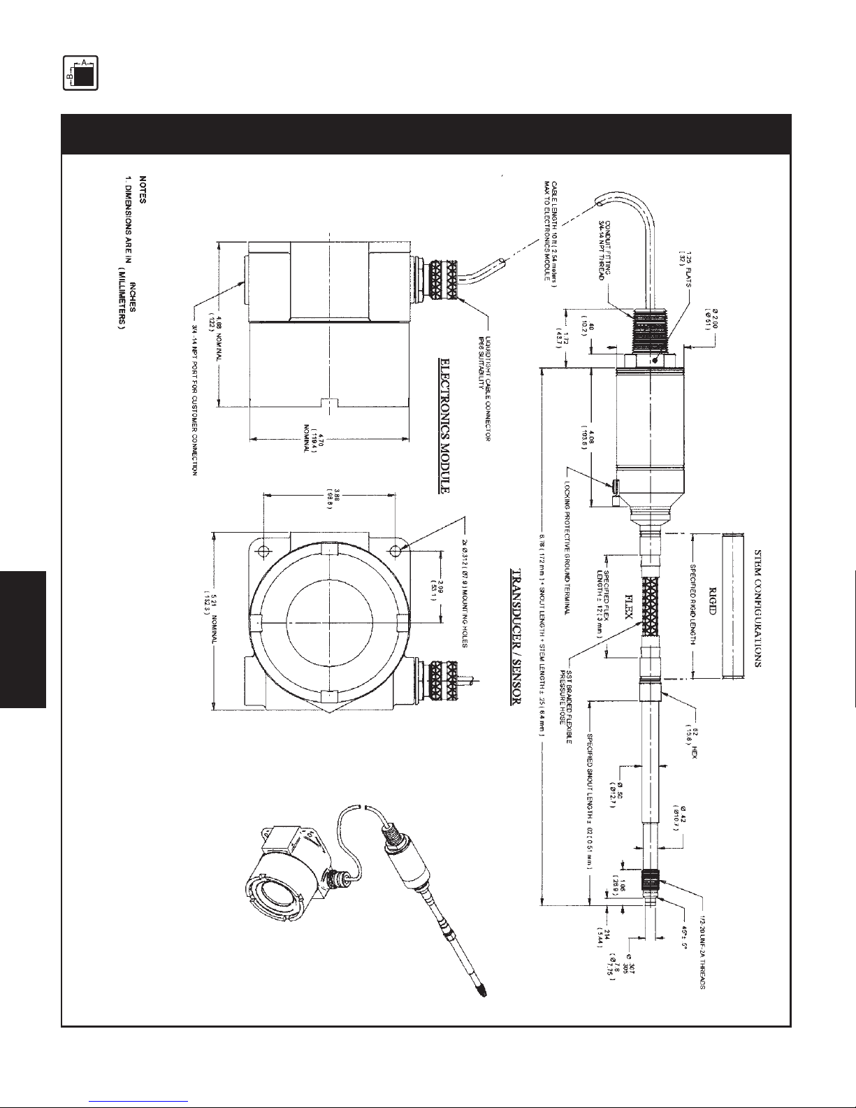
Fig. 3-1Fig. 3-1
Fig. 3-1Fig. 3-1
Fig. 3-1
IPX II Models S1192, S2192, N1192 & N2192IPX II Models S1192, S2192, N1192 & N2192
IPX II Models S1192, S2192, N1192 & N2192IPX II Models S1192, S2192, N1192 & N2192
IPX II Models S1192, S2192, N1192 & N2192
Page 15

15
TECHNICAL DATA
3.88
( 98.6 )
2.09
( 53.1 )
2x
O
.312 (
O
7.9 ) MOUNTIN G HOLES
5.21
( 132.3 )
NOMINAL
4.70
( 119.4 )
4.88
( 122 )
M18X1.5THREAD
45
v
30'
44
v
30'
.80
20.3
.236
.227
5.99
5.77
.550
13.97
.630
.627
16.00
15.93
O
.394
.392
10.01
9.96
O
SNOUT
HEX
.62
( 15.8 )
.50
O
(
O
12.7 )
SST BRAIDED FLEXIBLE
PRESSURE HOSE
BENDIX CONNECTOR
PT1H-14-15P OR EQUIVALENT
LOCKING PROTE CTIVE GROUND TERMINAL
4.08
( 103.6 )
2.00
O
(
O
.51 )
SPECIFIED FLEX
LENGTH
u
.12 (3mm)
TRANSDUCER/SENSOR
FLEX
RIGID
STEM CONFI GURATIONSSTEM CONFI GURATIONS
SPECIFIED RIGID LENGTH
SPECIFIED SNOUT LENG TH
u
.02 ( .51mm )
6.78 ( 172 mm ) + SNOUT LENGTH+ STEM LENGTH
u
.25(6.4mm)
10 ft ( 2.54 meters)
CABLE TO ELECTRONICS MODULE
BENDI X CONNEC TOR
PT06W-14-15S
OR EQUIVALENT
LIQUIDTIGHT CABLE CONNECTOR
IP66 SUITABILITY
NOMINAL
NOMINAL
ELECTRONICSMODULE
3/4 -14 NPT PORT FOR
CUSTOMER CONNECTION
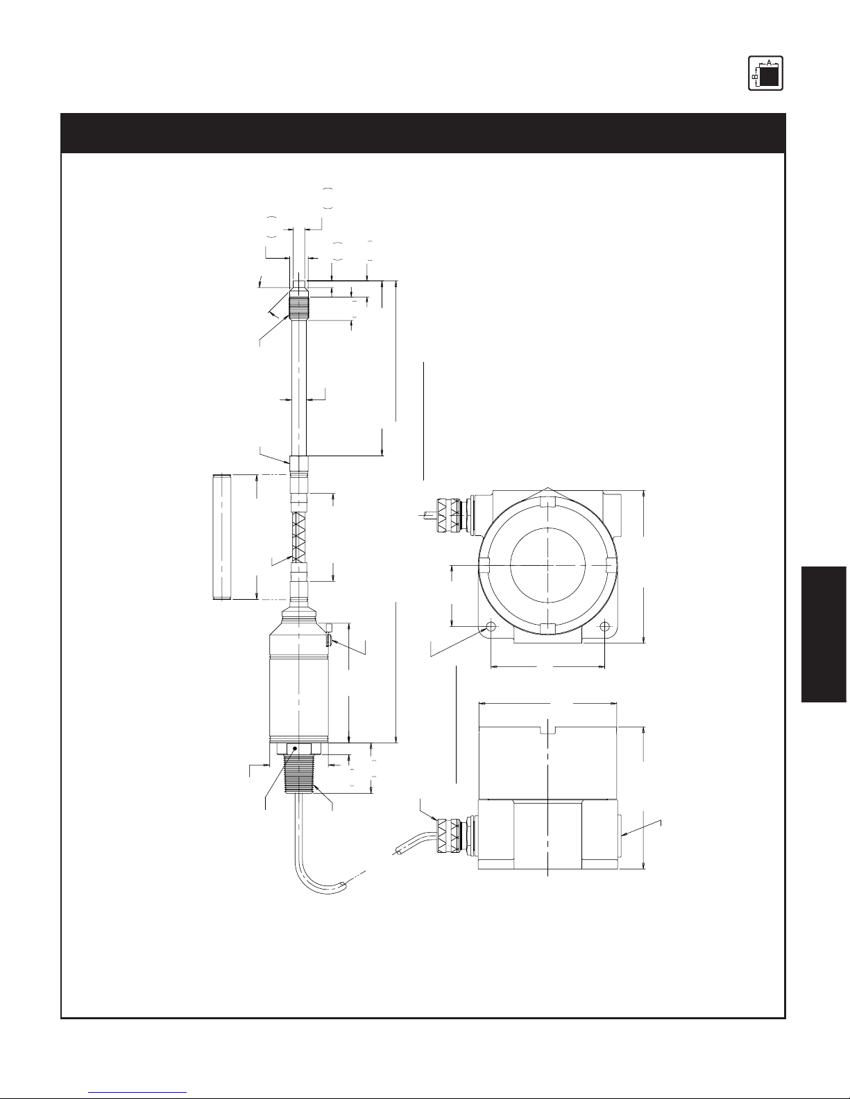
Fig. 3-2Fig. 3-2
Fig. 3-2Fig. 3-2
Fig. 3-2
IPX II Models S1193, S2193, N1193 & N2193IPX II Models S1193, S2193, N1193 & N2193
IPX II Models S1193, S2193, N1193 & N2193IPX II Models S1193, S2193, N1193 & N2193
IPX II Models S1193, S2193, N1193 & N2193
Page 16
16
TECHNICAL DATA
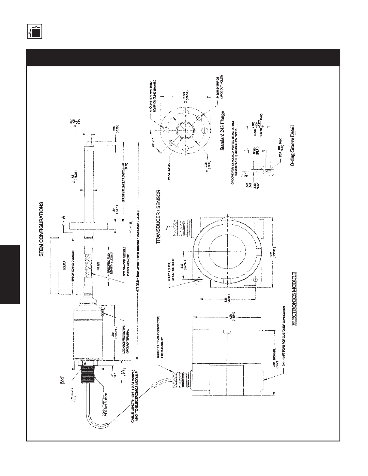
Fig. 3-3Fig. 3-3
Fig. 3-3Fig. 3-3
Fig. 3-3
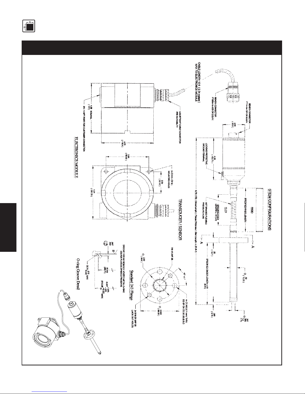
IPX II Models S1194, S2194, N1194 & N2194IPX II Models S1194, S2194, N1194 & N2194
IPX II Models S1194, S2194, N1194 & N2194IPX II Models S1194, S2194, N1194 & N2194
IPX II Models S1194, S2194, N1194 & N2194
Page 17
17
TECHNICAL DATA
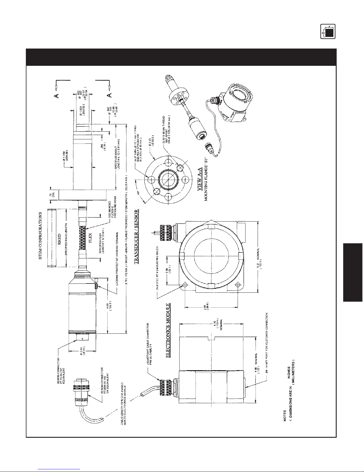
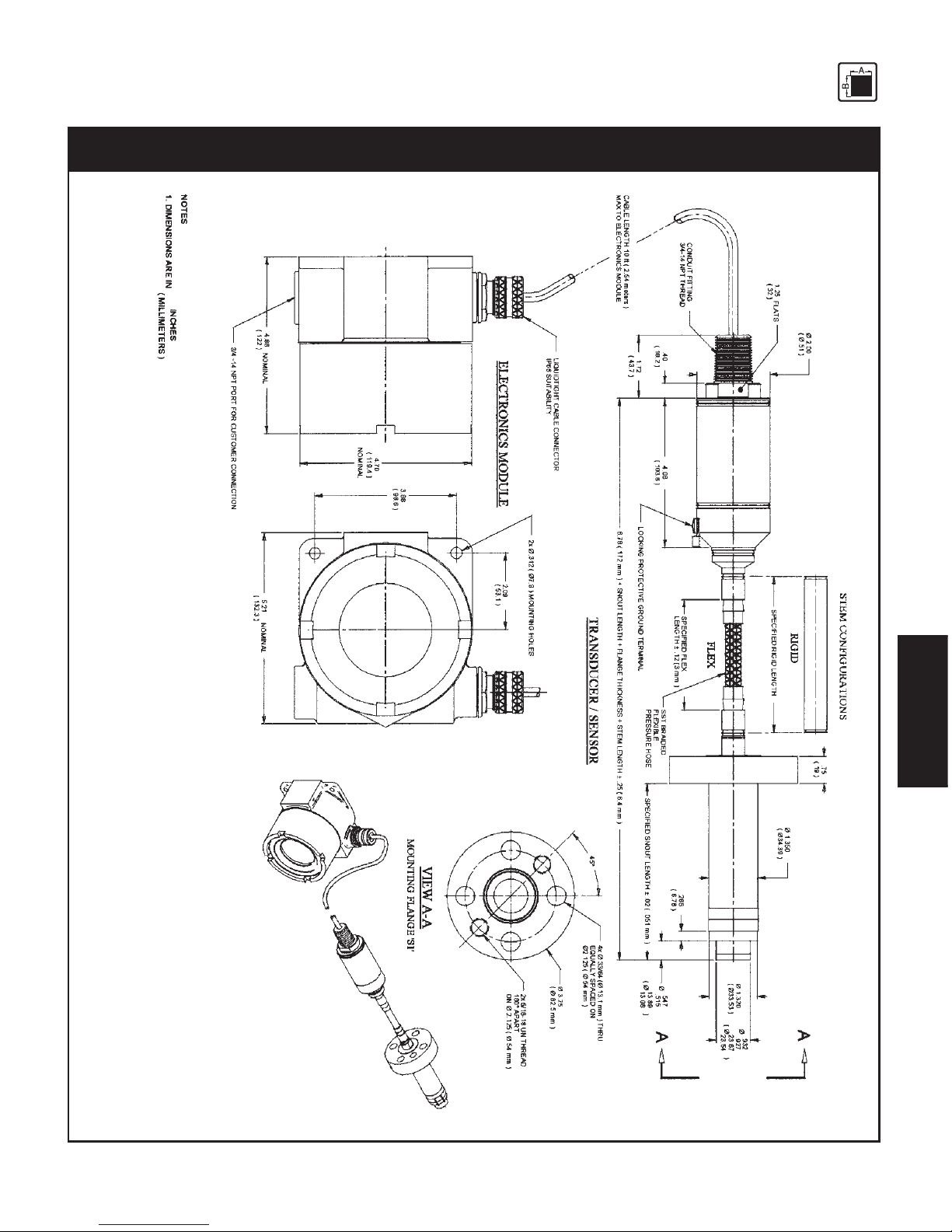
Fig. 3-4Fig. 3-4
Fig. 3-4Fig. 3-4
Fig. 3-4
IPX II Models S1195, S2195, N1195 & N2195IPX II Models S1195, S2195, N1195 & N2195
IPX II Models S1195, S2195, N1195 & N2195IPX II Models S1195, S2195, N1195 & N2195
IPX II Models S1195, S2195, N1195 & N2195
Page 18
18
TECHNICAL DATA
Fig. 3-5Fig. 3-5
Fig. 3-5Fig. 3-5
Fig. 3-5
IPX II Models E1192 & E2192IPX II Models E1192 & E2192
IPX II Models E1192 & E2192IPX II Models E1192 & E2192
IPX II Models E1192 & E2192
Page 19
19
TECHNICAL DATA
M18X1.5THREAD
45
v
30'
44
v
30'
.80
20.3
.236
.227
5.99
5.77
.550
13.97
.630
.627
16.00
15.93
O
.394
.392
10.01
9.96
O
SNOUT
HEX
.62
( 15.8 )
.50
O
(
O
12.7 )
SST BRAIDED FLEXIBLE
PRESSURE HOSE
LOCKING PROTECT IVE GROUND TERMINAL
4.08
( 103.6 )
2.00
O
(
O
.51 )
SPECIFIED FLEX
LENGTH
u
.12 (3mm)
TRANSDUCER/SENSOR
FLEX
RIGID
STEM CONFI GURATIONSSTEM CONF IGURATIONS
SPECIFIED RIGID LENGTH
SPECIFIED SNOUT LENGT H
u
.02 ( .51mm )
6.78 ( 172 mm ) + SNOUT LENGTH+ STEM LENGTH
u
.25(6.4mm)
10 ft ( 2.54 meters )
CABLE TO ELECTRONICS MODULE
FLATS
1.25
(32)
CONDUIT FITTI NG
3/4-14 NPT THREAD
3/4 -14 NPT PORT FOR
CUSTOMER CONNECTION
ELECTRONICSMODULE
NOMINAL
NOMINAL
LIQUIDTIGHT CABLE CONNECTOR
IP66 SUITABILITY
4.88
( 122 )
4.70
( 119.4 )
NOMINAL
5.21
( 132.3 )
2x
O
.312 (
O
7.9 ) MOUNTIN G HOLES
2.09
( 53.1 )
3.88
( 98.6 )
.40
10.2
1.72
43.8
Fig. 3-6Fig. 3-6
Fig. 3-6Fig. 3-6
Fig. 3-6
IPX II Models E1193 & E2193IPX II Models E1193 & E2193
IPX II Models E1193 & E2193IPX II Models E1193 & E2193
IPX II Models E1193 & E2193
Page 20
20
TECHNICAL DATA
Fig. 3-7Fig. 3-7
Fig. 3-7Fig. 3-7
Fig. 3-7
IPX II Models E1194 & E2194IPX II Models E1194 & E2194
IPX II Models E1194 & E2194IPX II Models E1194 & E2194
IPX II Models E1194 & E2194
Page 21
21
TECHNICAL DATA
Fig. 3-Fig. 3-
Fig. 3-Fig. 3-
Fig. 3-
Fig. 3-8Fig. 3-8
Fig. 3-8Fig. 3-8
Fig. 3-8
IPX II Models E1195 & E2195IPX II Models E1195 & E2195
IPX II Models E1195 & E2195IPX II Models E1195 & E2195
IPX II Models E1195 & E2195
Page 22

22
FUNCTION
4.4.
4.4.
4.
FF
FF
F
UNCTIONUNCTION
UNCTIONUNCTION
UNCTION
4.1 Construction ....................................................................................................................... 22
4.2 Description of Functions ...................................................................................................... 22
4.2.1 Theory of Operation ............................................................................................................ 23
4.2.2 Mechanical ......................................................................................................................... 23
4.2.3 Electrical ............................................................................................................................ 24
4.14.1
4.14.1
4.1
CC
CC
C
ONSTRUCTIONONSTRUCTION
ONSTRUCTIONONSTRUCTION
ONSTRUCTION
The PTs of series IPX II are industry standard.
The main advantages are:
• Intrinsically safe EEx ia IIC T4
• temperature compensated
• HART protocol based
• resistance to aggressive media
• insensitivity to electromagnetic radiation (EMC)
• liquid-filled transmission system (mercury)
• pressure measurements in plastic melt up to a temperature of 350°C
4.24.2
4.24.2
4.2
DD
DD
D
ESCRIPTIONESCRIPTION
ESCRIPTIONESCRIPTION
ESCRIPTION
OFOF
OFOF
OF
F F
F F
F
UNCTIONSUNCTIONS
UNCTIONSUNCTIONS
UNCTIONS
The Dynisco IPX II Series of Smart Pressure Transmitters are microprocessor based instruments that
incorporate advanced software techniques and modern sensor design. New, proprietary sensor
processing methods ensure the highest quality and reliability to meet Dynisco’s standards.
The IPX II Series is designed for applications that require high accuracy, even under wide variations
in process temperature. With the capability for up to 6-to-1 span turndown, one pressure range can
be used in several different applications, reducing spare parts inventory. And the IPX II Series’ remote
digital communication utilizing the industry standard HART protocol allows transmitter parameter
changes to be made from safe areas, increasing operator safety.
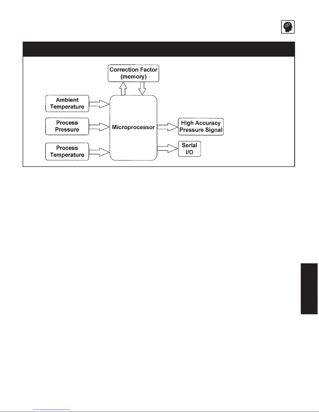
The IPX II Series of Smart Pressure Transmitters are characterized for process temperature effects,
providing an optional linearized stable, temperature reading via 4-20 mA output. Figure 4-1
illustrates the operation of the transmitter in the form of a block diagram. The process temperature
signal is available through the HART protocol. An optional dual LCD will display pressure or
temperature measurements in real-time.
Page 23
23
FUNCTION
Fig. 4-1Fig. 4-1
Fig. 4-1Fig. 4-1
Fig. 4-1
Operation in Block FormOperation in Block Form
Operation in Block FormOperation in Block Form
Operation in Block Form
In addition to the standard analog output, the IPX II Series supports remote digital communications
compatible with the HART Communicator (product of Emerson). The Model 275 can communicate
with IPX II Series transmitters from the control room, at the transmitter site, or from any convenient
junction box or wiring termination point in the measurement loop. The model 275 may be used to
configure the IPX II Series of transmitters or to test the control loop.
4.2.14.2.1
4.2.14.2.1
4.2.1
TT
TT
T
HEHE
HEHE
HE
ORYORY
ORYORY
ORY
OFOF
OFOF
OF
O O
O O
O
PERAPERA
PERAPERA
PERA
TIONTION
TIONTION
TION
The IPX II Smart Pressure Transmitter is a microprocessor-based device capable of measuring process
pressure to within 0.15% of the specified range. It is compensated for temperature effects at the
process end as well as the electronics end by using RTD’s and compensating software customized
for each unit.
The IPX II Series can be broken down into two distinct subsections, mechanical and electrical. The
following describes each in detail.
4.2.24.2.2
4.2.24.2.2
4.2.2
MM
MM
M
EE
EE
E
CHANICALCHANICAL
CHANICALCHANICAL
CHANICAL
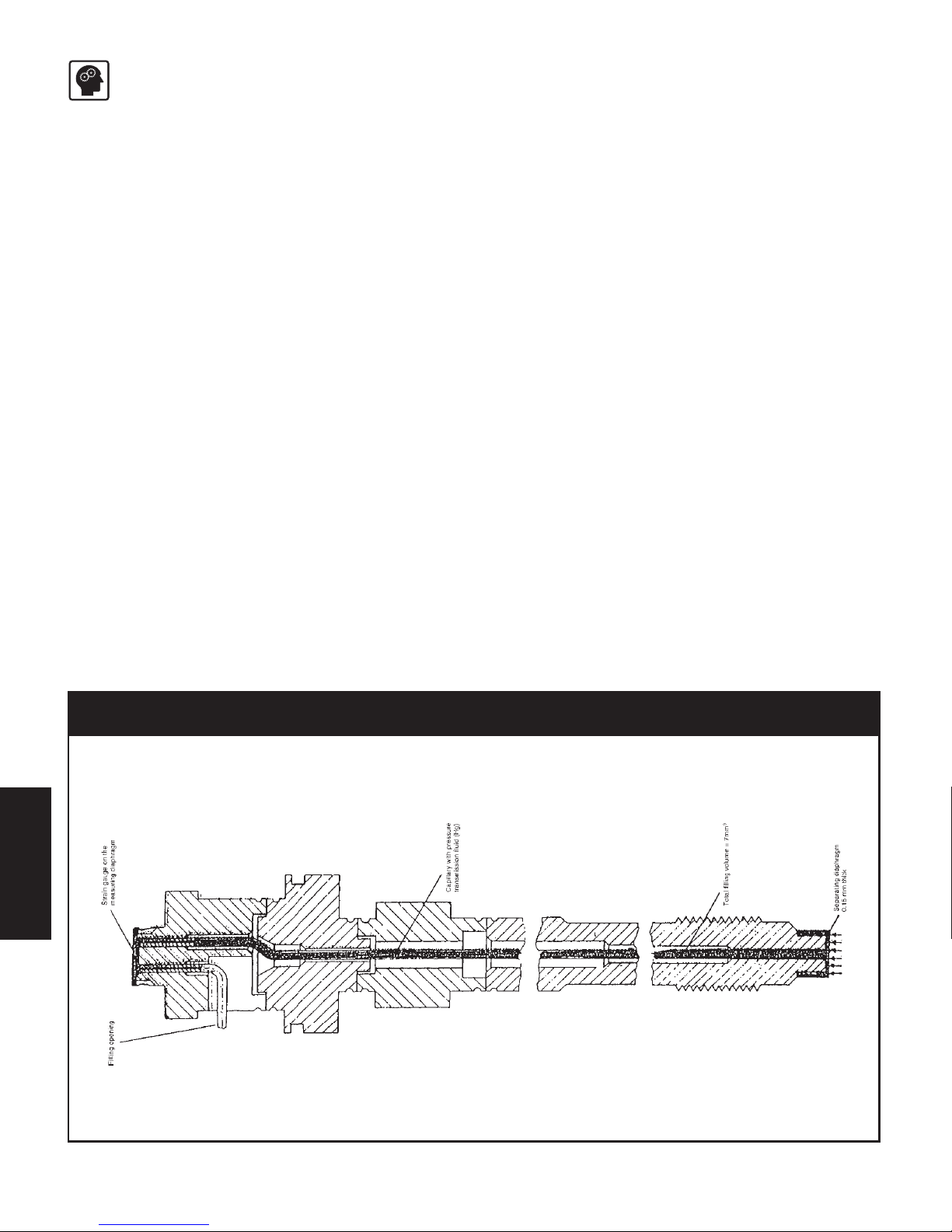
The mechanical system (filled assembly) consists of a lower diaphragm, a filled capillary tube, and
an upper diaphragm with a sputtered thin film strain gage. The filled assembly transmits pressure
from the process to the strain gage diaphragm where it is converted to an electrical signal. The filled
assembly isolates the electronics from the high process temperatures.
The elThe el
The elThe el
The el
ectrectr
ectrectr
ectr
oniconic
oniconic
onic
ss
ss
s
hou hou
hou hou
hou
ss
ss
s
inin
inin
in
g ig i
g ig i
g i
ss
ss
s
mm
mm
m
atat
atat
at
ed wed w
ed wed w
ed w
ith a sith a s
ith a sith a s
ith a s
pecpec
pecpec
pec
ificific
ificific
ific
sen sen
sen sen
sen
sor asor a
sor asor a
sor a
ss
ss
s
sembsemb
sembsemb
semb
lyly
lyly
ly
. Do not. Do not
. Do not. Do not
. Do not
mi mi
mi mi
mi
xx
xx
x
and m and m
and m and m
and m
atat
atat
at
cc
cc
c
h houh hou
h houh hou
h hou
ss
ss
s
inin
inin
in
gg
gg
g
ss
ss
s
and sen and sen
and sen and sen
and sen
sorsor
sorsor
sor
s.s.
s.s.
s.
The lower diaphragm is the surface in contact with the media being measured. This diaphragm can
be made from a choice of materials. The standard material is heat-treated 15-5 stainless steel. This
has average corrosion and abrasion resistance and is similar to 17-4 stainless steel. Other materials are
Page 24
24
FUNCTION
also available including Hastelloy C-276 which has excellent corrosion resistant properties (but is not
good for abrasion). For other materials please consult the factory.
Behind the lower diaphragm is a capillary tube filled to the upper diaphragm. As the process
pressure deflects the lower diaphragm, the fill is displaced through the capillary tube to deflect the
upper diaphragm.
The upper diaphragm has a 5000 ohm thin film strain gage element deposited on it in the
configuration of a Wheatstone Bridge. The deflection of the upper diaphragm causes a change in the
resistance of the strain gage and hence a change in the balance of the bridge. The amount of
imbalance is directly proportional to the applied pressure. This completes the translation of pressure
applied to the lower diaphragm into a usable electrical signal.
4.2.34.2.3
4.2.34.2.3
4.2.3
EE
EE
E
LELE
LELE
LE
CTRICALCTRICAL
CTRICALCTRICAL
CTRICAL
The low level output signal from the bridge is amplified via an instrumentation amp circuit. The
amplified signal then goes to the input of the analog-to-digital (A/D) converter.
Once the microprocessor has the converted voltage input from the A/D converter, the compensation
algorithms are executed. The unit is compensated for any errors introduced by temperature effects on
the gauge, snout electronics, and the nonlinearities of the pressure measurement itself. The corrected
digital signal is sent to a digital-to-analog (D/A) converter which modulates the current of the unit’s
power supply between 4 and 20 milliamps for an output current proportional to the applied
pressure.
Fig. 4-Fig. 4-
Fig. 4-Fig. 4-
Fig. 4-
22
22
2
Functioning Principle of the PT of the IPX II SeriesFunctioning Principle of the PT of the IPX II Series
Functioning Principle of the PT of the IPX II SeriesFunctioning Principle of the PT of the IPX II Series
Functioning Principle of the PT of the IPX II Series
Page 25

25
FUNCTION
Figure 4-3 illustrates typical wiring connections between the HART Communicator and any
compatible device.
Fig. 4-Fig. 4-
Fig. 4-Fig. 4-
Fig. 4-
33
33
3
CC
CC
C
onnectinonnectin
onnectinonnectin
onnectin
g the HARg the HAR
g the HARg the HAR
g the HAR
T CT C
T CT C
T C
ommuommu
ommuommu
ommu
nicnic
nicnic
nic
atat
atat
at
or tor t
or tor t
or t
o the IPXo the IPX
o the IPXo the IPX
o the IPX
II II
II II
II
Explosion can result in death or serious injury. Before connecting the
HART Communicator in an explosive atmosphere, make sure the instruments in the
loop are installed in accordance with intrinsically safe or nonincentive fields wiring
practices. For intrinsically safe and FM wiring connections, see the HART 275
Communication Manual.
Page 26

26
TRANSPORT
5.5.
5.5.
5.
TT
TT
T
RANSRANS
RANSRANS
RANS
PORPOR
PORPOR
POR
TT
TT
T
/ D / D
/ D / D
/ D
ELIVERYELIVERY
ELIVERYELIVERY
ELIVERY
5.1 Transport / packing / transport damage ............................................................................... 26
5.2 Storage .............................................................................................................................. 26
5.3 Scope of delivery ................................................................................................................ 26
TT
TT
T
oo
oo
o
xx
xx
x
icic
icic
ic
h h
h h
h
azaz
azaz
az
arar
arar
ar
d!d!
d!d!
d!
The PT contains a small amount of mercury (Hg) as its transmission medium. If the
diaphragm is damaged, mercury may escape.
Never transport or store the PT without the protective shell bolted in place. Remove the
shell shortly before installation.
IfIf
IfIf
If
mer mer
mer mer
mer
cc
cc
c
urur
urur
ur
yy
yy
y
i i
i i
i
ss
ss
s
inh inh
inh inh
inh
alal
alal
al
ed or swed or sw
ed or swed or sw
ed or sw
alal
alal
al
lolo
lolo
lo
ww
ww
w
ed, seeked, seek
ed, seeked, seek
ed, seek
medic medic
medic medic
medic
alal
alal
al
att att
att att
att
ention immediention immedi
ention immediention immedi
ention immedi
atat
atat
at
elyely
elyely
ely
..
..
.
Mercury is hazardous waste and must be disposed of in accordance with applicable
laws.
DD
DD
D
YNISCYNISC
YNISCYNISC
YNISC
OO
OO
O will accept defective PTs.
If mercury escapes, use airtight packaging!
ESD sensitive component. Electrostatic discharge may damage the PT. Take ESD
precautions.
5.15.1
5.15.1
5.1
TT
TT
T
RANSRANS
RANSRANS
RANS
PORPOR
PORPOR
POR
TT
TT
T
//
//
/
PP
PP
P
AA
AA
A
CKINGCKING
CKINGCKING
CKING
//
//
/
TRANSTRANS
TRANSTRANS
TRANS
PORPOR
PORPOR
POR
TT
TT
T
DD
DD
D
AMAGEAMAGE
AMAGEAMAGE
AMAGE
• Do not let the PT be damaged by other items during transit.
• Use only the original packaging.
• Report transport damage to
DD
DD
D
YNISCYNISC
YNISCYNISC
YNISC
OO
OO
O immediately in writing.
5.25.2
5.25.2
5.2
SS
SS
S
TT
TT
T
ORAGEORAGE
ORAGEORAGE
ORAGE
• Store the PT in original packaging only.
• Protect against dust and moisture.
5.35.3
5.35.3
5.3
SS
SS
S
CC
CC
C
OPEOPE
OPEOPE
OPE
OFOF
OFOF
OF
DELIVERYDELIVERY
DELIVERYDELIVERY
DELIVERY
• PT with diaphragm protection cap
• Fastening clip (transmitter with flexible stem only)
• Calibration sheet
• Operating manual with declaration of conformity
Page 27

27
ASSEMBLY
6.6.
6.6.
6.
AA
AA
A
SS
SS
S
SS
SS
S
EMBLEMBL
EMBLEMBL
EMBL
YY
YY
Y
6.1 Mounting hole ..................................................................................................................... 27
6.2 Checking the mounting hole ................................................................................................ 29
6.3 Mounting the Pressure Transmitter ....................................................................................... 30
6.4 Mounting PTs with flexible stem ............................................................................................ 31
6.5 Mounting PTs with flange.....................................................................................................32
6.6 Electrical connection ........................................................................................................... 32
6.6.1 EMC / CE compliant connection ........................................................................................... 33
6.7 Connection assignments ..................................................................................................... 33
Ambient temperature for the electronics housing max. +80°C (safety class T4 max.).
Higher temperatures can result in damage and malfunction.
Do not install the pressure transmitter in places where this temperature is exceeded.
6.16.1
6.16.1
6.1
MM
MM
M
OUNTINGOUNTING
OUNTINGOUNTING
OUNTING
H H
H H
H
OLEOLE
OLEOLE
OLE
To produce the 1/2-20 UNF mounting hole, use only
DD
DD
D
YNISCYNISC
YNISCYNISC
YNISC
OO
OO
O machining tool kit (DYNISCO
P/N 200925). To produce the M18 x 1.5 moutning hole, use only
DD
DD
D
YNISCYNISC
YNISCYNISC
YNISC
OO
OO
O machining tool kit
(DYNISCO P/N 200105).
• Drill the mounting hole as shown in fig. 6-1, 6-2, 6-3, 6-4.
Fig. 6-1Fig. 6-1
Fig. 6-1Fig. 6-1
Fig. 6-1
Mounting Hole xx192xMounting Hole xx192x
Mounting Hole xx192xMounting Hole xx192x
Mounting Hole xx192x
Page 28

28
ASSEMBLY
Fig. 6-2Fig. 6-2
Fig. 6-2Fig. 6-2
Fig. 6-2
Mounting hole xx193xxMounting hole xx193xx
Mounting hole xx193xxMounting hole xx193xx
Mounting hole xx193xx
Fig. 6-2Fig. 6-2
Fig. 6-2Fig. 6-2
Fig. 6-2
Mounting hole xx194xxMounting hole xx194xx
Mounting hole xx194xxMounting hole xx194xx
Mounting hole xx194xx
M18 X 1.5
a O
.004TA
.401
.399
10.2mm
10.1mm
O
.638
.634
16.2mm
16.1mm
.160
4.1mm
1.000
25.4mm
MIN FULL THD
.242
6.1mm
.787
20mm
O
MIN
Snout Length - .200 MAX
(5.1 mm)
46°
44°
- A -
Page 29

29
ASSEMBLY
Fig. 6-4Fig. 6-4
Fig. 6-4Fig. 6-4
Fig. 6-4
Mounting hole xx195xxMounting hole xx195xx
Mounting hole xx195xxMounting hole xx195xx
Mounting hole xx195xx
When reworking the mounting hole, pay particular attention to the centricity of:
• the hole,
• the thread and
• the sealing surface.
Pressure sealing takes place on the 45° beveled sealing surface or on the front cylindrical section of the
PT with an O-ring (see figures 6-1, 6-2, 6-3, 6-4).
The sealing surface must be:
• correctly machined
• free from marks and rough edges
• free from solidified plastic residue.
6.26.2
6.26.2
6.2
CC
CC
C
HEHE
HEHE
HE
CKINGCKING
CKINGCKING
CKING
THETHE
THETHE
THE
MOUNTINGMOUNTING
MOUNTINGMOUNTING
MOUNTING
HOLEHOLE
HOLEHOLE
HOLE
((
((
(
NONO
NONO
NO
TT
TT
T
FLANGEDFLANGED
FLANGEDFLANGED
FLANGED
MODELSMODELS
MODELSMODELS
MODELS
))
))
)
• Paint the test bolt DYNISCO on the marked area (figure 6-5, item 1) with marking ink up to the thread.
Page 30

30
ASSEMBLY
Fig. 6-5Fig. 6-5
Fig. 6-5Fig. 6-5
Fig. 6-5
TT
TT
T
ee
ee
e
ss
ss
s
tt
tt
t
Bo Bo
Bo Bo
Bo
ltlt
ltlt
lt
w w
w w
w
ith Mith M
ith Mith M
ith M
arkark
arkark
ark
inin
inin
in
g Inkg Ink
g Inkg Ink
g Ink
• Insert the test bolt in the mounting hole.
• Twist it in by hand until the two sealing surfaces make contact.
• Remove and examine the test bolt.
The only acceptable abrasion of marking ink is at the sealing edge (45°), evenly over the entire
circumference.
If the ink has been rubbed off in other places too:
• rework the mounting hole.
6.36.3
6.36.3
6.3
MM
MM
M
OUNTINGOUNTING
OUNTINGOUNTING
OUNTING
THETHE
THETHE
THE
P P
P P
P
RERE
RERE
RE
SS
SS
S
SURESURE
SURESURE
SURE
TT
TT
T
RANSRANS
RANSRANS
RANS
MITMIT
MITMIT
MIT
TERTER
TERTER
TER
Mounting and electrical connection of the PT must be done by specialists with EMC
training, following all applicable regulations, and in
prpr
prpr
pr
ee
ee
e
ss
ss
s
ss
ss
s
urur
urur
ur
elel
elel
el
ee
ee
e
ss
ss
s
s, s,
s, s,
s,
vv
vv
v
oo
oo
o
ltlt
ltlt
lt
agag
agag
ag
e-fre-fr
e-fre-fr
e-fr
ee,ee,
ee,ee,
ee,
intrinintrin
intrinintrin
intrin
ss
ss
s
icic
icic
ic
alal
alal
al
lyly
lyly
ly
s s
s s
s
afaf
afaf
af
ee
ee
e condition with the
mm
mm
m
acac
acac
ac
hine swhine sw
hine swhine sw
hine sw
itit
itit
it
cc
cc
c
hed offhed off
hed offhed off
hed off.
The machine must be secured against being switched back on!The machine must be secured against being switched back on!
The machine must be secured against being switched back on!The machine must be secured against being switched back on!
The machine must be secured against being switched back on!
TT
TT
T
oo
oo
o
xx
xx
x
icic
icic
ic
h h
h h
h
azaz
azaz
az
arar
arar
ar
d!d!
d!d!
d!
The PT contains a small amount of mercury (Hg) as its transmission medium. If the
diaphragm is damaged, mercury may escape.
Never transport or store the PT without the protective cap bolted in place. Remove the cap
shortly before installation.
IfIf
IfIf
If
mer mer
mer mer
mer
cc
cc
c
urur
urur
ur
yy
yy
y
i i
i i
i
ss
ss
s
inh inh
inh inh
inh
alal
alal
al
ed or swed or sw
ed or swed or sw
ed or sw
alal
alal
al
lolo
lolo
lo
ww
ww
w
ed, seeked, seek
ed, seeked, seek
ed, seek
medic medic
medic medic
medic
alal
alal
al
att att
att att
att
ention immediention immedi
ention immediention immedi
ention immedi
atat
atat
at
ely!ely!
ely!ely!
ely!
ESD sensitive component. Electrostatic discharge may damage the PT. Take ESD
precautions.
Before mounting the PT, check the mounting hole carefully. The PT must only be
mounted in holes that satisfy the requirements stipulated in section 6.1. A hole that does
not satisfy these requirements can damage the PT.
Page 31

31
ASSEMBLY
Before mounting the PT, ensure that the mounting hole is free from plastic residue. Remove
plastic residue with the
DD
DD
D
YNISCYNISC
YNISCYNISC
YNISC
OO
OO
O cleaning tool kit. A test bolt is included with this cleaning
set.
To prevent the PT from sticking permanently in the mounting hole, coat the thread section of
the transmitter with high temperature resistant grease or a suitable parting agent.
• Check the mounting hole with the test bolt, and clean with cleaning set if necessary.
• Coat the thread section of the transmitter with high temperature resistant grease or a suitable
parting agent.
Always use a spanner applied to the designated hexagon collar when screwing the PT in
and out. Do not apply the tool to the housing or housing / sensor connection!
Maximum mounting torque 500 inch-pounds. If the mounting torque is too high, the PT
may be damaged or its zero point may shift.
• Screw the PT into the mounting hole and tighten.
6.46.4
6.46.4
6.4
MM
MM
M
OUNTINGOUNTING
OUNTINGOUNTING
OUNTING
P P
P P
P
TT
TT
T
SS
SS
S
WITHWITH
WITHWITH
WITH
F F
F F
F
LEXIBLELEXIBLE
LEXIBLELEXIBLE
LEXIBLE
SS
SS
S
TEMTEM
TEMTEM
TEM
Mounting a PT with a flexible stem to the pressure sensor is done analogously to the procedure in
6.3.
Avoid kinking or crushing the flexible stem.
Minimum bending radius
•
1” (25 mm)1” (25 mm)
1” (25 mm)1” (25 mm)
1” (25 mm) for protected capillary
The connector must be easily accessible (on connector versions).
• Mount the electronics housing of the PT with the fastening clip. See mounting example in figure
6-6.
• Additionally secure the flexible stem between the electronics housing with a standard cable clip.
Page 32

32
ASSEMBLY
Fig. 6-6Fig. 6-6
Fig. 6-6Fig. 6-6
Fig. 6-6
Mounting Example for Sensor Portion of IPX II with Flexible StemMounting Example for Sensor Portion of IPX II with Flexible Stem
Mounting Example for Sensor Portion of IPX II with Flexible StemMounting Example for Sensor Portion of IPX II with Flexible Stem
Mounting Example for Sensor Portion of IPX II with Flexible Stem
6.56.5
6.56.5
6.5
II
II
I
NSNS
NSNS
NS
TT
TT
T
ALLINGALLING
ALLINGALLING
ALLING
THETHE
THETHE
THE
F F
F F
F
LANGEDLANGED
LANGEDLANGED
LANGED
P P
P P
P
RERE
RERE
RE
SS
SS
S
SURESURE
SURESURE
SURE
TT
TT
T
RANSRANS
RANSRANS
RANS
MITMIT
MITMIT
MIT
TERTER
TERTER
TER
Installation of the pressure transmitter with flexible connection to the pressure transducer is
analogous to the procedure described under 6.3, except mounting torque is different. See
specification section for details.
6.66.6
6.66.6
6.6
EE
EE
E
LELE
LELE
LE
CTRICALCTRICAL
CTRICALCTRICAL
CTRICAL
C C
C C
C
ONNEONNE
ONNEONNE
ONNE
CTIONCTION
CTIONCTION
CTION
Mounting and electrical connection of the PT must be done by specialists with EMC
training, following all applicable regulations, and in
prpr
prpr
pr
ee
ee
e
ss
ss
s
ss
ss
s
urur
urur
ur
elel
elel
el
ee
ee
e
ss
ss
s
s, s,
s, s,
s,
vv
vv
v
oo
oo
o
ltlt
ltlt
lt
agag
agag
ag
e-fre-fr
e-fre-fr
e-fr
ee,ee,
ee,ee,
ee,
intrinintrin
intrinintrin
intrin
ss
ss
s
icic
icic
ic
alal
alal
al
lyly
lyly
ly
s s
s s
s
afaf
afaf
af
ee
ee
e condition with the
mm
mm
m
acac
acac
ac
hine swhine sw
hine swhine sw
hine sw
itit
itit
it
cc
cc
c
hed offhed off
hed offhed off
hed off.
The mThe m
The mThe m
The m
acac
acac
ac
hine muhine mu
hine muhine mu
hine mu
ss
ss
s
tt
tt
t
be sec be sec
be sec be sec
be sec
urur
urur
ur
ed aged ag
ed aged ag
ed ag
ainain
ainain
ain
ss
ss
s
tt
tt
t
bein bein
bein bein
bein
g swg sw
g swg sw
g sw
itit
itit
it
cc
cc
c
hed bhed b
hed bhed b
hed b
acac
acac
ac
kk
kk
k
on! on!
on! on!
on!
ExpExp
ExpExp
Exp
lolo
lolo
lo
ss
ss
s
ion hion h
ion hion h
ion h
azaz
azaz
az
arar
arar
ar
d!d!
d!d!
d!
The pressure transmitter must be connected using a 2x2-core, twisted cable (blue cable
sheath).
Do not lay connecting cables in the direct vicinity of cables carrying higher voltage or
used to switch inductive or capacitive loads.
Operate only with an intrinsically safe, EMC compliant power supply with the following
specifications when employing the pressure 4-20 mA output:
Page 33

33
ASSEMBLY
Supply voltage max. 30 V DC
Current output max. 125 mA
Power output max. 900 mW
Inductivity max. 0.26 mH
Capacity max. 9.7 nF
Operate only with an intrinsically safe, EMC compliant power supply with the following
specifications when employing the temperature 4-20 mA output:
Supply voltage max. 30 V DC
Current output max. 125 mA
Power output max. 900 mW
Inductivity max. 0 mH
Capacity max. 52 nF
ESD sensitive component. Electrostatic discharge may damage the PT. Take ESD
precautions.
The electrical connection must comply with EMC requirements.
If the electrical connection is not made as described in chapter 6.6.1, or if cables /
cable connectors / cable glands other than those stipulated by
DD
DD
D
YNISCYNISC
YNISCYNISC
YNISC
OO
OO
O are used,
DD
DD
D
YNISCYNISC
YNISCYNISC
YNISC
OO
OO
O cannot guarantee that EMC requirements will be satisfied.
6.6.16.6.1
6.6.16.6.1
6.6.1
EMC / CE CEMC / CE C
EMC / CE CEMC / CE C
EMC / CE C
OMPLIANTOMPLIANT
OMPLIANTOMPLIANT
OMPLIANT
C C
C C
C
ONNECTIONONNECTION
ONNECTIONONNECTION
ONNECTION
• Earth the machine section with the screw-in trunnion / mounting hole for the PT in accordance
with regulations. The PT must be connected to earth via the screw-in trunnion / mounting hole.
• Connect the shield of the connecting cable on both sides, making sure it conducts with full and
continuous contact.
• When introducing the connecting cable into an EMC compliant switch cabinet, for example,
connect the shield correctely (cable gland, conducting, full contact, continuous) to the
conductive housing or route it via built-in cable connector that is also connected to the
conductive housing.
• Connect unused cable cores or free cable ends correctely to the cable shield on both sides.
6.76.7
6.76.7
6.7
CC
CC
C
ONNEONNE
ONNEONNE
ONNE
CTIONCTION
CTIONCTION
CTION
A A
A A
A
SS
SS
S
SIGNMENTSIGNMENT
SIGNMENTSIGNMENT
SIGNMENT
SS
SS
S
Page 34

34
COMMISSIONING
77
77
7
..
..
.
CC
CC
C
OMMISSIONINGOMMISSIONING
OMMISSIONINGOMMISSIONING
OMMISSIONING
7.1 Installation and mounting ..................................................................................................... 35
7.1.1a Hazardous area installations ................................................................................................ 35
7.1.1b Intrinsically safe installations ................................................................................................ 35
7.1.1c Temperature Environment..................................................................................................... 37
7.1.1d Electrical Guidelines ............................................................................................................. 37
7.1.2 Power supply ....................................................................................................................... 37
7.1.2a Non-intrinsically safe power supply ....................................................................................... 37
7.1.2b Intrinsically safe power supply .............................................................................................. 37
7.1.3 Mounting the transmitter ......................................................................................................37
7.1.3a Gaskets for mounting xxx195x transmitter ............................................................................. 37
7.1.4 Installation of electronics .................................................................................................... 38
7.1.4a Process Electronics Housing ................................................................................................ 38
7.1.4b Mounting the process electronics housing ............................................................................ 39
7.1.4c Conduit mounting ................................................................................................................ 39
7.1.5 Electrical installation ........................................................................................................... 39
7.1.5a Temperature output.............................................................................................................. 41
7.1.5b 4-20 mA transmitter output cable .......................................................................................... 41
7.1.5c Output terminals/cable ....................................................................................................... 42
7.1.5d Case ground ....................................................................................................................... 42
7.2 Configuration using the display ............................................................................................ 43
7.2.1 Optional analog operating mode w/display .......................................................................... 43
7.2.2 Configuring the IPX II ........................................................................................................... 44
7.2.2a Operate mode .................................................................................................................... 44
7.2.2b Entering operate mode ......................................................................................................... 45
7.2.2c Select display status ........................................................................................................... 46
7.2.2d Sensor units ....................................................................................................................... 46
7.2.2e Sensor temperature units .................................................................................................... 48
7.2.2f Sensor position adjust ......................................................................................................... 49
7.2.2g Change zero ........................................................................................................................ 50
7.2.2h Changing full scale output .................................................................................................... 52
7.2.2i Line frequency filter ............................................................................................................. 54
7.2.2j Select transmitter fail safe .................................................................................................... 55
7.2.2k Trim 4mA .............................................................................................................................. 56
7.2.2l Trim 20mA ............................................................................................................................ 57
7.2.2m Sensor zero trim ................................................................................................................... 58
7.2.2n Sensor full scale trim ............................................................................................................ 59
7.2.2o Reset sensor trim ................................................................................................................ 60
7.2.2p Offset .................................................................................................................................. 61
7.2.2q Select language .................................................................................................................. 62
7.2.2r Return to operate mode ....................................................................................................... 63
7.2.3 IPX II display flow chart for configuring using the display ....................................................... 64
Page 35

35
COMMISSIONING
77
77
7
.1.1
.1.1
.1
II
II
I
NSNS
NSNS
NS
TT
TT
T
ALLAALLA
ALLAALLA
ALLA
TIONTION
TIONTION
TION
ANDAND
ANDAND
AND
M M
M M
M
OUNTINGOUNTING
OUNTINGOUNTING
OUNTING
Please read the entire manual prior to installation and use.
• Do not remove protective cap until ready to install.
• Prior to initial installation, verify correct machining of mounting hole.
• When reinstalling, make sure mounting hole is clear of frozen plastic.
• Transducer should be removed when at operating temperature (no pressure in system).
7.1.17.1.1
7.1.17.1.1
7.1.1
AA
AA
A
HH
HH
H
AZARDOUSAZARDOUS
AZARDOUSAZARDOUS
AZARDOUS
A A
A A
A
REAREA
REAREA
REA
I I
I I
I
NSNS
NSNS
NS
TT
TT
T
ALLAALLA
ALLAALLA
ALLA
TIONSTIONS
TIONSTIONS
TIONS
Dynisco’s IPX II Series of Smart Pressure Transmitters are designed with circuitry suitable for
operation in a Class I , Division 1, Groups B, C & D, Class I/II, Division 2, Groups E, F & G
hazardous area. An explosion-proof electronics housing is standard on all IPX II Series models. The
specific approvals carried by individual transmitters are marked on the label. Refer to the product
data sheet for the most current information on these approvals.
7.1.17.1.1
7.1.17.1.1
7.1.1
BB
BB
B
II
II
I
NTRINSICALLNTRINSICALL
NTRINSICALLNTRINSICALL
NTRINSICALL
YY
YY
Y
SS
SS
S
AFEAFE
AFEAFE
AFE
I I
I I
I
NSNS
NSNS
NS
TT
TT
T
ALLAALLA
ALLAALLA
ALLA
TIONSTIONS
TIONSTIONS
TIONS
Dynisco’s IPX II Series of Smart Pressure Transmitters are designed with circuitry suitable for
operation in Intrinsically safe environments, with an approval code of EEx ia IIC T4.
The customer is required to install an approved galvanic barrier with entity parameters from DrawingThe customer is required to install an approved galvanic barrier with entity parameters from Drawing
The customer is required to install an approved galvanic barrier with entity parameters from DrawingThe customer is required to install an approved galvanic barrier with entity parameters from Drawing
The customer is required to install an approved galvanic barrier with entity parameters from Drawing
000092.000092.
000092.000092.
000092.
The specific approvals carried by individual transmitters are marked on the label. Refer to the product
data sheet for the most current information on these approvals.
Each sensor cable supplied with a cap plug (Dynisco P/N 598091) to protect the Bendix
connector from environmental conditions. Do not remove cap plug until you are ready to
connect to the sensor assembly.
Page 36

36
COMMISSIONING
3. ANY POSITIVE POLARITY SHUNT ZENER DIODE BARRIER APPROVED BY THE APPLICABLE AGENCY
USED IN THE APPLICABLE GROUPS:
FMRC & CSA - GROUPS B, C & D
CENELEC - GROUPS IIB +H2, IIB & IIA
WITH THE FOLLOWING OUTPUT PARAMETERS:
Voc orVtlessthanorequal to 30VDC
Isc orItlessthanorequal to 125 mA
Ca greater thanorequal to Ci + C cable
La greater thanorequal to Li + L cable
5. SYSTEM LABEL TO BE AFFIXED AT THE INTER FACE OF 'IS' OR 'NON- IS'' CIRCUITS OR AD JACENT TO
THE PRINCIPAL APPARATUS.
4. THE INS TALLATION INCLUD ING THE BARRIER EARTHING ARRANGEMENTS MUS T COMPLY WITH THE
INSTALLATION REQUIREMENTS OF THE COUNTRY OF USE:
* FOR CENELEC MEMBERS: IEC 1010-PT1 (Safety Requirements ForElectricalEquipmentFor
Measurement, Controland Laboratory Use - General Requirements) which is similar to B S EN 61010.
2. CABLE CAPACI TANCE AND INDUCTANCE PLUS THE I.S. APPA RATUS UNPROTECTED CAPACITANCE
(Ci) AND INDUCTANCE (Li) MUST NOT EXCEED THE ALLOWED CAPACITANCE (Ca) AND INDUCTANCE
(La) INDICATED ON THE ASSOCIA TED APPARATUS.
1. THE ELECTRICAL CIRCUIT I N THE HAZARDOUS AREA MUST BE C APABLE OF WIT HSTANDING AN AC
TEST VOLTAGE OF 230 VOLTS R.M.S. TO EARTH OR FRAME OF THE APPARATUS FOR ONE MINUTE.
NOTES:
HAZARDOUS AREA
SINGLE
CHANNEL
BARRIER
SINGLE
CHANNEL
BARRIER
NON-HAZARDOUS AREA
APARATUS UNSPECIFIED
EXCEPT THAT IT MUST NOT BE
SUPPLIED FROM NOR CONTAIN
UNDER NORMAL OR ABNORMAL
CONDITIONS ASOURCE OF
POTENT IALWITH RESPECT TO
EARTH IN EXCESS OF 250
VOLTSRMSOR250VOLTSDC
VR1500
ADAPTIVE INSTRUMENTS CORP.
577 M AIN ST.
HUDS ON MA.01749
USA
NON-HAZARDOUS AREA
(CLASS I, DIVISION 1 GROUPS B, C & D)
(ZONE0, GROUP IIB + H2, IIB, IIA)
DUAL CHANNEL
NOTE 3
II
II
I
NSNS
NSNS
NS
TT
TT
T
ALLAALLA
ALLAALLA
ALLA
TIONTION
TIONTION
TION
D D
D D
D
RARA
RARA
RA
WINGWING
WINGWING
WING
FORFOR
FORFOR
FOR
I I
I I
I
NTRINSICALLNTRINSICALL
NTRINSICALLNTRINSICALL
NTRINSICALL
YY
YY
Y
SS
SS
S
AFEAFE
AFEAFE
AFE
M M
M M
M
ODELSODELS
ODELSODELS
ODELS
Page 37

37
COMMISSIONING
77
77
7
.1.1.1.1
.1.1.1.1
.1.1
CC
CC
C
TT
TT
T
EMPERAEMPERA
EMPERAEMPERA
EMPERA
TURETURE
TURETURE
TURE
E E
E E
E
NVIRONMENTNVIRONMENT
NVIRONMENTNVIRONMENT
NVIRONMENT
IPX II Series transmitter electronics will operate within specifications over the ambient temperature
range of 0°C to 80°C (32°F to 176°F). The location of the electronics housing should be in an area
where the ambient temperature is within this range.
77
77
7
.1.1.1.1
.1.1.1.1
.1.1
DD
DD
D
EE
EE
E
LECTRICALLECTRICAL
LECTRICALLECTRICAL
LECTRICAL
G G
G G
G
UIDELINESUIDELINES
UIDELINESUIDELINES
UIDELINES
Dynisco’s IPX II Series of Smart Pressure Transmitters provide a digitally enhanced 4-20 mA current
signal output that is transmitted to the control room via two wires. Proper electrical installation is
necessary to prevent errors due to electrical noise.
7.1.27.1.2
7.1.27.1.2
7.1.2
PP
PP
P
OO
OO
O
WERWER
WERWER
WER
SS
SS
S
UPPLUPPL
UPPLUPPL
UPPL
YY
YY
Y
7.1.27.1.2
7.1.27.1.2
7.1.2
AA
AA
A
NN
NN
N
ONON
ONON
ON
-I-I
-I-I
-I
NTRINSICALLNTRINSICALL
NTRINSICALLNTRINSICALL
NTRINSICALL
YY
YY
Y
SS
SS
S
AFEAFE
AFEAFE
AFE
P P
P P
P
OO
OO
O
WERWER
WERWER
WER
SS
SS
S
UPPLUPPL
UPPLUPPL
UPPL
YY
YY
Y
The power supply should provide 12-42 V dc. The load resistance is the sum of the resistance of the
signal leads and the load resistance of any indicator, controller, or other devices in the loop. Total
load resistance must be
22
22
2
50 ohms50 ohms
50 ohms50 ohms
50 ohms or greater for communication with the Model 275 HART
Communicator. Refer to Table 7-3.
7.1.27.1.2
7.1.27.1.2
7.1.2
BB
BB
B
II
II
I
NTRINSICALLNTRINSICALL
NTRINSICALLNTRINSICALL
NTRINSICALL
YY
YY
Y
SS
SS
S
AFEAFE
AFEAFE
AFE
P P
P P
P
OO
OO
O
WERWER
WERWER
WER
SS
SS
S
UPPLUPPL
UPPLUPPL
UPPL
YY
YY
Y
The power supply should provide 12-30 V dc. The load resistance is the sum of the resistance of the
signal leads and the load resistance of any indicator, controller, or other devices in the loop. See
technical specifications for complete power supply requirements.
7.1.37.1.3
7.1.37.1.3
7.1.3
MM
MM
M
OUNTINGOUNTING
OUNTINGOUNTING
OUNTING
THETHE
THETHE
THE
TT
TT
T
RANSRANS
RANSRANS
RANS
MITMIT
MITMIT
MIT
TERTER
TERTER
TER
Failure to use the recommended mounting hole may result in erroneous pressure measurement,
difficult transmitter removal, premature sensor failure, process fluid leaks, and personnel hazard. In
applications involving high temperature operation and/or repeated thermal cycling a good, high quality
anti-seize compound should be applied to threaded surfaces.
77
77
7
.1..1.
.1..1.
.1.
33
33
3
AA
AA
A
GG
GG
G
ASKETSASKETS
ASKETSASKETS
ASKETS
FORFOR
FORFOR
FOR
M M
M M
M
OUNTINGOUNTING
OUNTINGOUNTING
OUNTING
XX195X T XX195X T
XX195X T XX195X T
XX195X T
RANSMITTERRANSMITTER
RANSMITTERRANSMITTER
RANSMITTER
Different mounting gaskets are available. Refer to Table 7-1 for the correct mounting configuration for
proper installation.
Page 38

38
COMMISSIONING
TT
TT
T
abab
abab
ab
ll
ll
l
e 7e 7
e 7e 7
e 7
-1-1
-1-1
-1
VV
VV
V
ariouariou
ariouariou
ariou
ss
ss
s
Mou Mou
Mou Mou
Mou
ntinntin
ntinntin
ntin
g Gg G
g Gg G
g G
aa
aa
a
sksk
sksk
sk
etsets
etsets
ets
7.1.47.1.4
7.1.47.1.4
7.1.4
II
II
I
NSNS
NSNS
NS
TT
TT
T
ALLAALLA
ALLAALLA
ALLA
TIONTION
TIONTION
TION
OFOF
OFOF
OF
THETHE
THETHE
THE
E E
E E
E
LELE
LELE
LE
CTRONICCTRONIC
CTRONICCTRONIC
CTRONIC
SS
SS
S
7.1.47.1.4
7.1.47.1.4
7.1.4
AA
AA
A
PP
PP
P
ROCESSROCESS
ROCESSROCESS
ROCESS
E E
E E
E
LECTRONICSLECTRONICS
LECTRONICSLECTRONICS
LECTRONICS
H H
H H
H
OUSINGOUSING
OUSINGOUSING
OUSING
The IPX II Series of Smart Pressure Transmitters process housing always includes an electronics
module. An optional dual LCD display may be ordered. If the display option is selected the IPX II
Series Smart Pressure Transmitter is supplied with a glass viewing window. Figure 7-1 is an example
of the process housing with an optional glass viewing window.
Fig. 7Fig. 7
Fig. 7Fig. 7
Fig. 7
-1-1
-1-1
-1
PrPr
PrPr
Pr
ococ
ococ
oc
ee
ee
e
ss
ss
s
ss
ss
s
Hou Hou
Hou Hou
Hou
ss
ss
s
inin
inin
in
gg
gg
g
Page 39

39
COMMISSIONING
77
77
7
.1.4.1.4
.1.4.1.4
.1.4
BB
BB
B
MM
MM
M
OUNTINGOUNTING
OUNTINGOUNTING
OUNTING
THETHE
THETHE
THE
P P
P P
P
ROCESSROCESS
ROCESSROCESS
ROCESS
E E
E E
E
LECTRONICSLECTRONICS
LECTRONICSLECTRONICS
LECTRONICS
H H
H H
H
OUSINGOUSING
OUSINGOUSING
OUSING
The IPX II Series Smart Pressure Transmitter housing has two “feet” used for mounting on a flat
surface or on a pipe using a u-bolt pipe mounting bracket, see Figure 7-1.
The optional 2” Pipe Mounting Bracket kit can be supplied with the process electronics housing. This
mounting bracket can be set-up in a number of different orientations. The metal plate is attached to
the process housing with the kit’s enclosed hardware.
To remove the cover of the IPX II in a hazardous location the power to the transmitter
must be off. With the Intrinsically Safe product, galvanic barrier limits the power so it is
safe to remove cover.
In addition, if the LCD display option is utilized, the electronics inside the housing can be rotated in
90o intervals. To do this remove the two 6-32 machined screws, rotate the electronics to the required
position, and replace the two machined screws. Note the position of the screws may change
depending on the position of the electronics module.
7.1.47.1.4
7.1.47.1.4
7.1.4
CC
CC
C
CC
CC
C
ONDUITONDUIT
ONDUITONDUIT
ONDUIT
M M
M M
M
OUNTINGOUNTING
OUNTINGOUNTING
OUNTING
The weatherproof housing has two 3/4” female NPT conduit entries (one is used for the pressure
sensor input). These can be used to mount the housing directly onto the 3/4” male NPT ends of rigid
conduits. Alternatively, a union coupling can be placed between the weatherproof housing and the
wiring from the signal source.
All connections must be accessible in a Class 1 Division 1, Groups B, C & D instrument enclosureAll connections must be accessible in a Class 1 Division 1, Groups B, C & D instrument enclosure
All connections must be accessible in a Class 1 Division 1, Groups B, C & D instrument enclosureAll connections must be accessible in a Class 1 Division 1, Groups B, C & D instrument enclosure
All connections must be accessible in a Class 1 Division 1, Groups B, C & D instrument enclosure
(c(c
(c(c
(c
uu
uu
u
ss
ss
s
tt
tt
t
omer somer s
omer somer s
omer s
upup
upup
up
pp
pp
p
lied), inlied), in
lied), inlied), in
lied), in
ss
ss
s
tt
tt
t
alal
alal
al
ll
ll
l
ed per NEed per NE
ed per NEed per NE
ed per NE
CC
CC
C
(NFP (NFP
(NFP (NFP
(NFP
A 7A 7
A 7A 7
A 7
00
00
0
, Ar, Ar
, Ar, Ar
, Ar
tictic
tictic
tic
ll
ll
l
e 500). A jue 500). A ju
e 500). A jue 500). A ju
e 500). A ju
nction bonction bo
nction bonction bo
nction bo
xx
xx
x
i i
i i
i
ss
ss
s
r r
r r
r
equirequir
equirequir
equir
ed, per NFDed, per NFD
ed, per NFDed, per NFD
ed, per NFD
AA
AA
A
70, Article 500, so to terminate the output cables.70, Article 500, so to terminate the output cables.
70, Article 500, so to terminate the output cables.70, Article 500, so to terminate the output cables.
70, Article 500, so to terminate the output cables.
7.1.57.1.5
7.1.57.1.5
7.1.5
EE
EE
E
LELE
LELE
LE
CTRICALCTRICAL
CTRICALCTRICAL
CTRICAL
I I
I I
I
NSNS
NSNS
NS
TT
TT
T
ALLAALLA
ALLAALLA
ALLA
TIONTION
TIONTION
TION
The IPX II Series Smart Pressure Transmitter has two groups of terminals.
HAZARD: NevHAZARD: Nev
HAZARD: NevHAZARD: Nev
HAZARD: Nev
er poer po
er poer po
er po
ww
ww
w
er an eer an e
er an eer an e
er an e
xpxp
xpxp
xp
lolo
lolo
lo
ss
ss
s
ion prion pr
ion prion pr
ion pr
oofoof
oofoof
oof
pr pr
pr pr
pr
oductoduct
oductoduct
oduct
in a h in a h
in a h in a h
in a h
azaz
azaz
az
arar
arar
ar
doudou
doudou
dou
ss
ss
s
ar ar
ar ar
ar
ee
ee
e
a wa w
a wa w
a w
ith the inith the in
ith the inith the in
ith the in
ss
ss
s
trumenttrument
trumenttrument
trument
encenc
encenc
enc
lolo
lolo
lo
ss
ss
s
urur
urur
ur
e open.e open.
e open.e open.
e open.
Terminals 1 and 3 are the 4 to 20 mA output terminals. Terminal 2 is not used. These are normally
connected to the corresponding polarity terminals of the power supply of the current loop. Refer to
Figure 7-2 for the terminal connections arrangement.
Page 40

40
COMMISSIONING
Fig. 7-2Fig. 7-2
Fig. 7-2Fig. 7-2
Fig. 7-2
TT
TT
T
erminermin
erminermin
ermin
alal
alal
al
C C
C C
C
onnectiononnection
onnectiononnection
onnection
ss
ss
s
The use of an appropriate power supply is important. A 24 V dc supply having a current
handling capacity of at least 0.1A is commonly used. Always use a dc (direct current)
supply, or suitable size battery.
NevNev
NevNev
Nev
er cer c
er cer c
er c
onnectonnect
onnectonnect
onnect
the IPX the IPX
the IPX the IPX
the IPX
II II
II II
II
SerieSerie
SerieSerie
Serie
ss
ss
s
SmSm
SmSm
Sm
arar
arar
ar
tt
tt
t
Pr Pr
Pr Pr
Pr
ee
ee
e
ss
ss
s
ss
ss
s
urur
urur
ur
ee
ee
e
TT
TT
T
rr
rr
r
anan
anan
an
smittsmitt
smittsmitt
smitt
er direr dir
er direr dir
er dir
ectlyectly
ectlyectly
ectly
t t
t t
t
o 115Vo 115V
o 115Vo 115V
o 115V
AA
AA
A
CC
CC
C
or 2 or 2
or 2 or 2
or 2
30V30V
30V30V
30V
AA
AA
A
C.C.
C.C.
C.
With the power supply off, connect the (+) side of the power supply to the (+) OUT terminal of the
electronics module. Connect the (-) side of the power supply through a 250Ω resistor to the (-) OUT
terminal of the electronics module. See Figure 7-2. Connect the input terminals 1 and 3 in series
with the current loop to be measured. Terminal 1 should be more positive than 3.
Current Input High (+MA)
Current Input Low (-COM)
The output can be monitored by connecting a multi-meter in series with either of the two output
terminals, or by connecting a high impedance voltmeter across the 250Ω resistor. Turn on the power
supply. In about 5 seconds the IPX II Series Smart Pressure Transmitter loop current will settle to its
normal value in the range of 4 to 20 mA.
If the unit has been ordered with optional dual LCD display, the display and display adapter must be
removed to connect the 24 V dc power to the unit. The display pulls off the display adapter, see
Figure 7-3.
There are two types of display adapters, the standard without a second 4-20mA output for
temperature or an adapter with a second 4-20 mA output for temperature. The display adapter is
connected through standoff posts by two 6-32 screws.
Page 41

41
COMMISSIONING
Fig 7-3Fig 7-3
Fig 7-3Fig 7-3
Fig 7-3
DD
DD
D
ualual
ualual
ual
L L
L L
L
CD DiCD Di
CD DiCD Di
CD Di
ss
ss
s
pp
pp
p
ll
ll
l
aa
aa
a
yy
yy
y
w w
w w
w
ith an optionith an option
ith an optionith an option
ith an option
alal
alal
al
2nd 4- 2nd 4-
2nd 4- 2nd 4-
2nd 4-
20 mA 20 mA
20 mA 20 mA
20 mA
OutpOutp
OutpOutp
Outp
utut
utut
ut
Remove the screws to remove the adapter board. Carefully handle the adapter board and wiring to
avoid any damage. With the power supply off, connect the (+) side of the power supply to the (+)
OUT terminal of the electronics module. Connect the (-) side of the power supply through a 250Ω
resistor to the (-) OUT terminal of the electronics module. See Figure 7-2. Connect the input
terminals 1 and 3 in series with the current loop to be measured. Terminal 1 should be more positive
than 3.
7.1.57.1.5
7.1.57.1.5
7.1.5
AA
AA
A
TT
TT
T
EMPERAEMPERA
EMPERAEMPERA
EMPERA
TURETURE
TURETURE
TURE
O O
O O
O
UTPUTUTPUT
UTPUTUTPUT
UTPUT
If the optional second 4-20 mA adapter board was ordered, the terminals 1 (+), 2 (-) on the adapter
board would also be connected to the 24 V dc power supply. This will provide the snout temperature
from the RTD in the process (located next to the diaphragm). Replace the display by aligning the
holes with pins and pushing the display gently into place. At this time you are ready for set-up using
the display, or the optional SmartLink software/modem or the optional HART 275 communicator.
7.1.57.1.5
7.1.57.1.5
7.1.5
BB
BB
B
4–20 4–20
4–20 4–20
4–20
MM
MM
M
A A
A A
A
TT
TT
T
RANSRANS
RANSRANS
RANS
MITMIT
MITMIT
MIT
TERTER
TERTER
TER
O O
O O
O
UTPUTUTPUT
UTPUTUTPUT
UTPUT
C C
C C
C
ABLEABLE
ABLEABLE
ABLE
The IPX II is supplied with a 11.5’ (3.5 m) cable for the transmitter output. A breakdown of the wiring
schematic is displayed in Table 7-2.
Page 42

42
COMMISSIONING
TT
TT
T
abab
abab
ab
ll
ll
l
e 7e 7
e 7e 7
e 7
--
--
-
22
22
2
Output Cable Wiring SpecificationsOutput Cable Wiring Specifications
Output Cable Wiring SpecificationsOutput Cable Wiring Specifications
Output Cable Wiring Specifications
7.1.57.1.5
7.1.57.1.5
7.1.5
CC
CC
C
OO
OO
O
UTPUTUTPUT
UTPUTUTPUT
UTPUT
TT
TT
T
ERMINALSERMINALS
ERMINALSERMINALS
ERMINALS
/C/C
/C/C
/C
ABLEABLE
ABLEABLE
ABLE
The output terminals are connected to a power supply having a nominal 24 V dc voltage and
capable of supplying 100 mA for the IPX II. In the analog mode, these units require a maximum of
only 24 mA. Optionally a load resistor, typically
22
22
2
5050
5050
50
ΩΩ
ΩΩ
Ω, may be connected in series with either
terminal of the pressure transmitter (for HART digital communications with the IPX II, this 250Ω
resistor is required). The maximum series resistance in the circuit (including wiring lead resistance) can
be calculated using the formula:
Table 7-3 gives maximum series resistance:
TT
TT
T
abab
abab
ab
ll
ll
l
e 7e 7
e 7e 7
e 7
--
--
-
33
33
3
Maximum Series ResistanceMaximum Series Resistance
Maximum Series ResistanceMaximum Series Resistance
Maximum Series Resistance
7.1.57.1.5
7.1.57.1.5
7.1.5
DD
DD
D
CC
CC
C
ASEASE
ASEASE
ASE
G G
G G
G
ROUNDROUND
ROUNDROUND
ROUND
For safety, optimum performance and EMI immunity the case of the instrument should be connected
to a good local earth ground. When using grounded sensors that are connected to the local electrical
ground, the pressure transmitter case should be connected to that same ground point.
Page 43

43
COMMISSIONING
77
77
7
.2.2
.2.2
.2
CC
CC
C
ONFIGURAONFIGURA
ONFIGURAONFIGURA
ONFIGURA
TIONTION
TIONTION
TION
U U
U U
U
SINGSING
SINGSING
SING
THETHE
THETHE
THE
D D
D D
D
ISIS
ISIS
IS
PLAPLA
PLAPLA
PLA
YY
YY
Y
77
77
7
.2.1.2.1
.2.1.2.1
.2.1
OO
OO
O
PP
PP
P
TIONALTIONAL
TIONALTIONAL
TIONAL
A A
A A
A
NALNAL
NALNAL
NAL
OGOG
OGOG
OG
O O
O O
O
PERAPERA
PERAPERA
PERA
TINGTING
TINGTING
TING
M M
M M
M
ODEODE
ODEODE
ODE
WITHWITH
WITHWITH
WITH
D D
D D
D
ISIS
ISIS
IS
PLAPLA
PLAPLA
PLA
YY
YY
Y
If the IPX II Series Smart Pressure Transmitter was ordered with the display option, it has a small local
dual LCD display module plugged into the display adapter. The display option can be ordered from the
factory installed on the IPX II Series Smart Pressure Transmitter or can be ordered at a later date and
installed on site. Having the display option as part of the IPX II Series Smart Pressure Transmitter does not
affect its operation in the analog mode and the description of the previous section applies.
However, the display option does provide some very useful local indication of the measured
pressure, temperature and other diagnostic functions. Figure 7-4 below indicates the arrangement of
the display screen and some of the symbols that are available.
Fig. 7Fig. 7
Fig. 7Fig. 7
Fig. 7
--
--
-
44
44
4
DD
DD
D
ualual
ualual
ual
L L
L L
L
CD diCD di
CD diCD di
CD di
ss
ss
s
pp
pp
p
ll
ll
l
aa
aa
a
yy
yy
y
w w
w w
w
ith sith s
ith sith s
ith s
imuimu
imuimu
imu
ll
ll
l
atat
atat
at
ed red r
ed red r
ed r
ee
ee
e
aa
aa
a
doutdout
doutdout
dout
The top row displays the measured variable. A minus sign can be displayed if applicable. Depending
on the input selected the number of decimal places displayed changes.
The mid portion is an analog bar graph display showing the % of range based on the ZERO and
FULL-SCALE setting of the IPX II Series Smart Pressure Transmitter. When power is applied, the
leftmost segment of the bar graph, the 0%, and the 100% become energized. If the input signal is
below what the ZERO is set to, then the left arrow is energized. If the input signal is above the FULLSCALE setting, then the right arrow becomes energized.
The bottom portion of the LCD is capable of displaying alphanumeric messages. In normal operation
this row shows a label, which is factory set to display the model number and pressure unit. Seven or
eight characters are available per screen. The user may order a desired label in place of the model
number.
Page 44

44
COMMISSIONING
In the event of certain IPX II Series Smart Pressure Transmitter failure modes, the lower portion of the
display changes to either
SS
SS
S
F F
F F
F
AA
AA
A
ULUL
ULUL
UL
TT
TT
T or
XX
XX
X
F F
F F
F
AA
AA
A
ULUL
ULUL
UL
TT
TT
T.
This LCD display takes full advantage of the precision of the IPX II Series Smart Pressure Transmitter.
The digital display of the measurement does not include the small D/A error present in the analog
output. It provides highly accurate local indication of the measurement, local fault diagnostics, and
the IPX II Series Smart Pressure Transmitter identification. The LCD continues to display the measured
variable even if it is beyond the zero and span limits set for the analog output. The value of this
display as a set-up, calibration and reconfiguration tool may even be greater.
7.2.27.2.2
7.2.27.2.2
7.2.2
CC
CC
C
ONFIGURINGONFIGURING
ONFIGURINGONFIGURING
ONFIGURING
THETHE
THETHE
THE
IPX IPX
IPX IPX
IPX
II II
II II
II
If the optional dual LCD display is ordered, configuration of an IPX II Series Pressure Transmitter is
possible. This inexpensive option makes reconfiguration or re-ranging of the transmitter simple and
easy.
In the event that the dual LCD display is not purchased at the same time as the transmitter, one must
follow the field installation instructions supplied with the display very carefully to avoid damage to
the transmitter or the display, itself.
7.2.27.2.2
7.2.27.2.2
7.2.2
AA
AA
A
OO
OO
O
PERAPERA
PERAPERA
PERA
TETE
TETE
TE
M M
M M
M
ODEODE
ODEODE
ODE
The
OperOper
OperOper
Oper
atat
atat
at
e Modee Mode
e Modee Mode
e Mode will allow the user to do the following:
• See Display Status
• Select Pressure Units
• Select Process Temperature Units
• Sensor Position Adjust
• Change ZERO (Change the 4 mA Lower Range Value)
• Change FULL SCALE (Change the 20 mA Full Scale Value)
• Set Line Frequency Filter
• Select Transmitter Fail-safe
• Trim 4 mA (Trim the 4.0 mA output current)
• Trim 20 mA (Trim the 20.0 mA output current)
• Set Sensor Zero Trim
• Set Sensor Full Scale Trim
• Reset Sensor Trim
• Set Offset
• Change Language
• Return to Operate Mode
Each of these functions is presented in sequence on the LCD display.
Page 45

45
COMMISSIONING
To start the
OperOper
OperOper
Oper
atat
atat
at
e Modee Mode
e Modee Mode
e Mode, first connect the IPX II Series Smart Pressure Transmitter to an appropriate
DC power supply. Typically a 24 V dc supply is connected to the IPX II Transmitter. The power
supply’s (+) terminal is connected to the transmitter’s output (+) terminal and the (-) side of the power
supply is connected to the transmitter’s output (-) terminal. A minimum
22
22
2
5050
5050
50
ΩΩ
ΩΩ
Ω series resistor in the
loop is required. A process sensor must be connected to the transmitter’s input connectors for setting
up the transmitter.
7.2.27.2.2
7.2.27.2.2
7.2.2
BB
BB
B
EE
EE
E
NTERINGNTERING
NTERINGNTERING
NTERING
O O
O O
O
PERAPERA
PERAPERA
PERA
TETE
TETE
TE
M M
M M
M
ODEODE
ODEODE
ODE
Once the IPX II Series Smart Pressure Transmitter is powered up, the display comes on in the
standard operating mode. With the standard factory set-up and precess sensor connected, the dual
LCD display will give the following indication:
Note that when more than seven or eight characters are required to describe a function’s label, the
display will continuously alternate through multiple screens. In this section of the manual, placing
two or more display messages adjacently indicates alternating displays, as above. The dual LCD
display, with some functions, will display a numeric value on the top line of the display in addition
to a message on the lower display line.
The IPX II Smart Pressure transmitter may display a pressure, this is caused by the difference in the
elevation between the sensor and process connection. This is corrected in a set-up procedure called
Set Position Adjust.
Please note that if the display is plugged into the IPX II while it is powered up, the menu sequence
may not start at the beginning. To return the display to the normal operating mode power down the
IPX II without disconnecting the display or simply wait about two minutes for the transmitter to reset
itself.
Press and release the
NEXTNEXT
NEXTNEXT
NEXT key immediately followed by the
ENTERENTER
ENTERENTER
ENTER key. This will start the Operate
Mode. The
DISDIS
DISDIS
DIS
PLAPLA
PLAPLA
PLA
YY
YY
Y
MODE MODE
MODE MODE
MODE is the first set-up menu.
NONO
NONO
NO
TE:TE:
TE:TE:
TE: Whenever the IPX II Series Smart Pressure Transmitter is in the display set-up mode, if after
approximately 2 minutes there is no activation of the keypad the transmitter will return to the
OPERAOPERA
OPERAOPERA
OPERA
TETE
TETE
TE
MODE MODE
MODE MODE
MODE. One can also return to the
OPERAOPERA
OPERAOPERA
OPERA
TETE
TETE
TE
MODE MODE
MODE MODE
MODE at any point in during the
DISDIS
DISDIS
DIS
PLAPLA
PLAPLA
PLA
YY
YY
Y
MODEMODE
MODEMODE
MODE by removing power from the transmitter for about 30 seconds, then reapplying power.
Page 46

46
COMMISSIONING
77
77
7
.2.2.2.2
.2.2.2.2
.2.2
CC
CC
C
SS
SS
S
ELEELE
ELEELE
ELE
CTCT
CTCT
CT
D D
D D
D
ISIS
ISIS
IS
PLAPLA
PLAPLA
PLA
YY
YY
Y
SS
SS
S
TT
TT
T
AA
AA
A
TUSTUS
TUSTUS
TUS
Press the
ENTERENTER
ENTERENTER
ENTER key. This will allow you to set-up the transmitter using the Operate Mode. A flow
chart summarizing the operation is in section 7.2.3.
The
DISDIS
DISDIS
DIS
PLAPLA
PLAPLA
PLA
YY
YY
Y
SS
SS
S
TT
TT
T
AA
AA
A
TUSTUS
TUSTUS
TUS is the first function in the sequence. The display will read as follows to
indicate this position on the menu:
Press the
ENTERENTER
ENTERENTER
ENTER key to see the current set-up of the IPX II Series Smart Pressure Transmitter. Use the
NEXTNEXT
NEXTNEXT
NEXT key to continue onto the next function.
7.2.27.2.2
7.2.27.2.2
7.2.2
DD
DD
D
SS
SS
S
ENSORENSOR
ENSORENSOR
ENSOR
U U
U U
U
NITSNITS
NITSNITS
NITS
The
SS
SS
S
ELEELE
ELEELE
ELE
CT PRECT PRE
CT PRECT PRE
CT PRE
SS
SS
S
SURESURE
SURESURE
SURE
UNIT UNIT
UNIT UNIT
UNIT
SS
SS
S is the next function in the sequence. The display will sequence as
follows:
The factory set default is
PP
PP
P
SISI
SISI
SI. If the factory set default is the required pressure unit press the
NEXTNEXT
NEXTNEXT
NEXT
key to move onto the next function. If a change is required, press the
ENTERENTER
ENTERENTER
ENTER key to go into the list
of pressure units. Use the
NEXTNEXT
NEXTNEXT
NEXT key to sequence through the selectable pressure units. One can stop
at any one of the pressure selections by pressing the
ENTERENTER
ENTERENTER
ENTER key, this changes the IPX II to the
required units of pressure. The list of pressure units is listed below:
(Pounds per square inch)
Press the
NEXTNEXT
NEXTNEXT
NEXT key to go to the next unit (continue to do this until the desired pressure unit is listed
and then press
ENTERENTER
ENTERENTER
ENTER).
(Bar)
Page 47

47
COMMISSIONING
(Millibar)
(Grams per square centimeter)
(Kilograms per square centimeter)
(Pascal)
(Kilopascal)
(Torr)
(Atmospheres)
(Percent full scale)
(Megapascal)
Page 48

48
COMMISSIONING
(The “special” pressure units is a programmable engineering unit that is not already listed.)
(Inches of water)
(Inches of mercury)
(Feet of water)
(Millimeters of water)
After pressing
ENTERENTER
ENTERENTER
ENTER to select the desired pressure units the display returns to:
Press the
NEXTNEXT
NEXTNEXT
NEXT key to move on to the next function.
7.2.27.2.2
7.2.27.2.2
7.2.2
EE
EE
E
SS
SS
S
ENSORENSOR
ENSORENSOR
ENSOR
TT
TT
T
EMPERAEMPERA
EMPERAEMPERA
EMPERA
TURETURE
TURETURE
TURE
U U
U U
U
NITNIT
NITNIT
NIT
SS
SS
S
The
SS
SS
S
ELEELE
ELEELE
ELE
CT CT
CT CT
CT
TEMPERATEMPERA
TEMPERATEMPERA
TEMPERA
TURETURE
TURETURE
TURE
UNIT UNIT
UNIT UNIT
UNIT
SS
SS
S is the next function in the sequence. The display will read as
follows to indicate this position on the menu:
The factory set default is
DEDE
DEDE
DE
G CG C
G CG C
G C (°C). If the factory set default is the required temperature unit press
Page 49

49
COMMISSIONING
the
NEXTNEXT
NEXTNEXT
NEXT key to move onto the next function. If a change is required, press the
ENTERENTER
ENTERENTER
ENTER key to go into the
list of temperature units. Use the
NEXTNEXT
NEXTNEXT
NEXT key to sequence through the selectable temperature units. One
can stop at any one of the temperature selections by pressing the
ENTERENTER
ENTERENTER
ENTER key. This changes the IPX II
Series Smart Pressure Transmitter mode to the required temperature units. The list of temperature units is
listed below:
(Degrees Celcius)
Press the
NEXTNEXT
NEXTNEXT
NEXT key to go to the next unit (continue to do this until the desired temperature unit is
listed and then press
ENTERENTER
ENTERENTER
ENTER).
(Degrees Fahrenheit)
(Degrees Rankin)
(Degrees Kelvin)
After pressing
ENTERENTER
ENTERENTER
ENTER to select the desired temperature units the display returns to:
Press the
NEXTNEXT
NEXTNEXT
NEXT key to move onto the next function.
7.2.27.2.2
7.2.27.2.2
7.2.2
FF
FF
F
SS
SS
S
ENSORENSOR
ENSORENSOR
ENSOR
P P
P P
P
OO
OO
O
SITIONSITION
SITIONSITION
SITION
A A
A A
A
DJUSDJUS
DJUSDJUS
DJUS
TMENTTMENT
TMENTTMENT
TMENT
The next function of the IPX II Series Smart Pressure Transmitter will adjust the actual installed sensor
position. Any “shift” caused by elevation will be removed using this adjustment.
Failure to apply sensor position adjustment may cause inaccuracy in the pressure
measurement.
Page 50

50
COMMISSIONING
The display will sequence as follows:
Press the
ENTERENTER
ENTERENTER
ENTER key to begin the
SS
SS
S
ENSOR POENSOR PO
ENSOR POENSOR PO
ENSOR PO
SITION ADJUSSITION ADJUS
SITION ADJUSSITION ADJUS
SITION ADJUS
TMENTTMENT
TMENTTMENT
TMENT sequence of displays. The
sequence of displays will be follows (there are seven displays in this sequence):
Press the
ENTERENTER
ENTERENTER
ENTER key to set the sensor to zero. Press the
NEXTNEXT
NEXTNEXT
NEXT key to exit out of the
SENSORSENSOR
SENSORSENSOR
SENSOR
POPO
POPO
PO
SITION ADJUSSITION ADJUS
SITION ADJUSSITION ADJUS
SITION ADJUS
TMENTTMENT
TMENTTMENT
TMENT sequence. After pressing the
NEXTNEXT
NEXTNEXT
NEXT key the display returns to:
Press the
NEXTNEXT
NEXTNEXT
NEXT key again to go onto the next function.
7.2.27.2.2
7.2.27.2.2
7.2.2
GG
GG
G
CC
CC
C
HANGEHANGE
HANGEHANGE
HANGE
Z Z
Z Z
Z
EROERO
EROERO
ERO
The next function of the IPX II Series Smart Pressure Transmitter is
CHANGECHANGE
CHANGECHANGE
CHANGE
ZEROZERO
ZEROZERO
ZERO. The display will
read as follows:
The electronics will adjust the 4.0 mA output signal to the lower range value. Typically, this value is
set to zero. The numeric value in the upper portion of the LCD display is the current
ZEROZERO
ZEROZERO
ZERO value.
The
ZEROZERO
ZEROZERO
ZERO (known as the LOWER RANGE VALUE or LRV) can be changed, totally independent of the FULL
Page 51

51
COMMISSIONING
SCALE VALUE (known as the UPPER RANGE VALUE or URV) or the sensor position adjustment without the
use of any calibrators or external sensor inputs. To change to
ZEROZERO
ZEROZERO
ZERO, press the
ENTERENTER
ENTERENTER
ENTER key. The display
changes to:
This indicates the existing
ZEROZERO
ZEROZERO
ZERO is set to “plus” 0000.0. The question is asking if this value is to
remain positive. By pressing the
NEXTNEXT
NEXTNEXT
NEXT key the display will change to:
After determining whether the LRV, is to remain positive (PLUS ?) or negative (MINUS ?), press the
ENTERENTER
ENTERENTER
ENTER key. This display will change to:
The leftmost digit position will start blinking (shown in italics) denoting that the ten thousands
position needs to be changed. To change the thousands position, press the
NEXTNEXT
NEXTNEXT
NEXT key. The leftmost
digit will increment through 1 2 3 4 5 6 7 8 9 0. When the desired numeral is reached stop. Press the
ENTERENTER
ENTERENTER
ENTER key to accept the selection. If the numeral selected is zero then the display would change
to:
Selecting different pressure units will give you different upper range limits. Not all units of
pressure will, for example, allow you to change the thousands digit. These different units
will then have more rangability at the low end of the scale.
It is possible to apply and offset of the LRV up to 84% of the full-scale value. In certain applications,
the increased resolution would provide additional process data.
The second digit from the left will start blinking (shown above in italics) denoting the thousands
position is ready to be changed. As before, change the number in this digit position by continuously
pressing the
NEXTNEXT
NEXTNEXT
NEXT key until the desired numeral is reached. Then press the
ENTERENTER
ENTERENTER
ENTER key to select the
Page 52

52
COMMISSIONING
desired number and move to the next lower significant digit position. Each time the
NEXTNEXT
NEXTNEXT
NEXT key will cycle
through the ten choices for that digit position, the
ENTERENTER
ENTERENTER
ENTER key will display the selected number. Once the
digit position is changed, the next significant digit will blink. The legend on the display will change to:
Continue to modify the significant digits until the desired number is reached. After the final digit
position has been changed, pressing of the
ENTERENTER
ENTERENTER
ENTER key returns the transmitter to the alternating
display of:
Press the
NEXTNEXT
NEXTNEXT
NEXT key to proceed to the next menu selection,
CHANGECHANGE
CHANGECHANGE
CHANGE
FULL FULL
FULL FULL
FULL
SCALESCALE
SCALESCALE
SCALE.
7.2.27.2.2
7.2.27.2.2
7.2.2
HH
HH
H
CC
CC
C
HANGINGHANGING
HANGINGHANGING
HANGING
F F
F F
F
ULLULL
ULLULL
ULL
SS
SS
S
CALECALE
CALECALE
CALE
VV
VV
V
ALAL
ALAL
AL
UEUE
UEUE
UE
The next function of the IPX II Series Smart Pressure Transmitter is
CHANGECHANGE
CHANGECHANGE
CHANGE
FULL FULL
FULL FULL
FULL
SCALESCALE
SCALESCALE
SCALE. The
display will read:
To change the full-scale value press the
ENTERENTER
ENTERENTER
ENTER key. The procedure for selecting PLUS ? or MINUS ?
is identical to that described for
CHANGECHANGE
CHANGECHANGE
CHANGE
ZEROZERO
ZEROZERO
ZERO. Similarly, the procedure for changing each of the
digit positions is identical to that described for
CHANGECHANGE
CHANGECHANGE
CHANGE
ZEROZERO
ZEROZERO
ZERO.
Page 53

53
COMMISSIONING
The displays are listed below for changing the full scale value.
Press the
NEXTNEXT
NEXTNEXT
NEXT key to toggle between displays:
After determining whether the URV, is to remain positive (PLUS ?) or negative (MINUS ?), press the
ENTERENTER
ENTERENTER
ENTER key. The display will change to:
Continue to modify the significant digits until the desired number is reached. After the final digit
position has been changed, press the
ENTERENTER
ENTERENTER
ENTER key to return the transmitter to the alternating display
of:
Page 54

54
COMMISSIONING
Press the
NEXTNEXT
NEXTNEXT
NEXT key to proceed to the next menu selection,
LINELINE
LINELINE
LINE
FRE FRE
FRE FRE
FRE
QUENCYQUENCY
QUENCYQUENCY
QUENCY
FIL FIL
FIL FIL
FIL
TERTER
TERTER
TER.
7.2.27.2.2
7.2.27.2.2
7.2.2
II
II
I
LL
LL
L
INEINE
INEINE
INE
F F
F F
F
RERE
RERE
RE
QUENCYQUENCY
QUENCYQUENCY
QUENCY
F F
F F
F
ILIL
ILIL
IL
TERTER
TERTER
TER
The next function of the IPX II Series Smart Pressure Transmitter is
LINELINE
LINELINE
LINE
FRE FRE
FRE FRE
FRE
QUENCYQUENCY
QUENCYQUENCY
QUENCY
FIL FIL
FIL FIL
FIL
TERTER
TERTER
TER. This
function allows for selecting filtering of the signal based upon the input voltage. The display will
sequence as follows:
If the factory set default,
60 Hz60 Hz
60 Hz60 Hz
60 Hz, is the required frequency of filtering press the
NEXTNEXT
NEXTNEXT
NEXT key to move
onto the next function. If different filtering is required, press the
ENTERENTER
ENTERENTER
ENTER key to enter into the list of
filter choices. Use the
NEXTNEXT
NEXTNEXT
NEXT key to sequence through the selectable filter options. Stop at the
desired filter, select it by pressing the
ENTERENTER
ENTERENTER
ENTER key. The list of filter options are:
Press the
NEXTNEXT
NEXTNEXT
NEXT key to go to the next option (continue to do this until the desired additional filter is
listed and then press
ENTERENTER
ENTERENTER
ENTER).
After the filtering has been added, press the
ENTERENTER
ENTERENTER
ENTER key to return the transmitter to the alternating
display of:
Press the
NEXTNEXT
NEXTNEXT
NEXT key to proceed to the next menu selection,
SS
SS
S
ELEELE
ELEELE
ELE
CT CT
CT CT
CT
TRANSTRANS
TRANSTRANS
TRANS
MITMIT
MITMIT
MIT
TER FTER F
TER FTER F
TER F
AILAIL
AILAIL
AIL
SS
SS
S
AFEAFE
AFEAFE
AFE.
Page 55

55
COMMISSIONING
77
77
7
.2.2.2.2
.2.2.2.2
.2.2
JJ
JJ
J
SS
SS
S
ELECTELECT
ELECTELECT
ELECT
T T
T T
T
RANSMITTERRANSMITTER
RANSMITTERRANSMITTER
RANSMITTER
F F
F F
F
AILAIL
AILAIL
AIL
S S
S S
S
AFEAFE
AFEAFE
AFE
The next function of the IPX II Series Smart Pressure Transmitter is
SS
SS
S
ELEELE
ELEELE
ELE
CT CT
CT CT
CT
TRANSTRANS
TRANSTRANS
TRANS
MITMIT
MITMIT
MIT
TER FTER F
TER FTER F
TER F
AILAIL
AILAIL
AIL
SS
SS
S
AFEAFE
AFEAFE
AFE.
The display will sequence as follows (there are 4 displays):
Fail-safe allows the transmitter to change the 4-20 mA loop to display a failure condition. This failure
may be a sensor failure or a transmitter failure. The user may select to drive the loop to 22.0 mA,
corresponding to the “HIGH” selection, and/or to 3.6 mA, corresponding to the “LOW” selection, or
to turn the function “OFF”.
Press the
NEXTNEXT
NEXTNEXT
NEXT key to move onto the next function. To change the Fail Safe setting, press the
ENTERENTER
ENTERENTER
ENTER key to enter into the list of Fail Safe options use the
NEXTNEXT
NEXTNEXT
NEXT key to sequence through the
selectable Fail Safe options. Stop at desired Fail Safe options by pressing the
ENTERENTER
ENTERENTER
ENTER key. The list of
Fail Safe options are listed below:
Press the
NEXTNEXT
NEXTNEXT
NEXT key to go through the Fail Safe options (continue to do this until the desired option is
reached and then press
ENTERENTER
ENTERENTER
ENTER).
After the desired Fail Safe option has been selected, the transmitter will return to the alternating
display of:
Page 56

56
COMMISSIONING
Press the
NEXTNEXT
NEXTNEXT
NEXT key to proceed to the next menu selection,
TRIM 4 MATRIM 4 MA
TRIM 4 MATRIM 4 MA
TRIM 4 MA.
7.2.27.2.2
7.2.27.2.2
7.2.2
KK
KK
K
TT
TT
T
RIMRIM
RIMRIM
RIM
4 4
4 4
4
MM
MM
M
AA
AA
A
The next function of the IPX II Series Smart Pressure Transmitter is
TRIM 4 MATRIM 4 MA
TRIM 4 MATRIM 4 MA
TRIM 4 MA
..
..
. This allows trimming
of the 4 mA output current. The display will sequence as follows:
This function is only for the purpose of adjusting the 4 mA limit of the IPX II Series Smart
Pressure Transmitter loop current to be exactly 4 mA according to the plant’s local
standard. This is NOT for the purpose of ranging the transmitter!
The 4 mA limit is factory calibrated to a precision standard. Do not arbitrarily trim the output unless
a qualified and accurate local standard is available to measure the adjusted 4 mA output! Also note
that the 4 mA limit should not be trimmed by more than about + 50 µA, or the transmitter operation
may be impaired.
If trimming the 4 mA limit is still required press the
ENTERENTER
ENTERENTER
ENTER key. The IPX II Series Pressure
Transmitter will now output a current equal to its internally set 4 mA current. This 4 mA value should
be read on an external meter and compared to a local standard. It is advisable to use a well
calibrated voltmeter to make these comparisons. It is very possible that the IPX II Series transmitter
will be more accurate than many voltmeters. In this case, trimming will make the IPX II Series Smart
Pressure Transmitter less accurate rather than more accurate!
Once
TRIM 4 MATRIM 4 MA
TRIM 4 MATRIM 4 MA
TRIM 4 MA has been selected, the display will alternate as follows:
By pressing the
NEXTNEXT
NEXTNEXT
NEXT key the display then changes to and alternates:
Page 57

57
COMMISSIONING
When it is decided whether to raise or lower the output current, press the
NEXTNEXT
NEXTNEXT
NEXT key, to raise (lower) the 4
mA output signal. Now every time the
NEXTNEXT
NEXTNEXT
NEXT key is pressed, the display blinks, and the 4 mA output limit
decreases (-) or increases (+). The decrease or increase is in approximately 2µA increments.
Once the desired trim is reached, press the
ENTERENTER
ENTERENTER
ENTER key to return to either:
or
Pressing the
NEXTNEXT
NEXTNEXT
NEXT key changes to the next function.
7.2.27.2.2
7.2.27.2.2
7.2.2
LL
LL
L
TT
TT
T
RIMRIM
RIMRIM
RIM
20 20
20 20
20
MM
MM
M
AA
AA
A
The next function of the IPX II Series Smart Pressure Transmitter is
TRIM 20 MATRIM 20 MA
TRIM 20 MATRIM 20 MA
TRIM 20 MA. This allows trimming
of the 20 mA output current. The display will sequence as follows:
This function is only for the purpose of adjusting the 20 mA limit of the IPX II Series
Smart Pressure Transmitter loop current to be exactly 20 mA according to the plants
local standard. This is NOT for the purpose of ranging the transmitter!
The 20 mA limit is factory calibrated to a precision standard. Do not arbitrarily trim the output unless
a qualified and accurate local standard is available to measure the adjusted 20 mA output! Also note
that the 20 mA limit should not be trimmed by more than about + 50 µA, or the transmitter operation
may be impaired.
If trimming the 20 mA limit is still desired press
ENTERENTER
ENTERENTER
ENTER. The IPX II Series Smart Pressure Transmitter
will now output a current equal to its internally set 20 mA current. This 20 mA value should be read
on an external meter and compared to a local standard. It is advisable to use a well calibrated
voltmeter to make these comparisons. It is very possible that the IPX II Series Smart Pressure
Transmitter will be more accurate than many voltmeters. In this case, trimming will make the IPX II
Series Smart Pressure Transmitter less accurate rather than more accurate!
Once
TRIM 20 MATRIM 20 MA
TRIM 20 MATRIM 20 MA
TRIM 20 MA has been selected, the display will alternate as follows:
Page 58

58
COMMISSIONING
By pressing the
NEXTNEXT
NEXTNEXT
NEXT key the display changes to:
When it is decided whether to raise or lower the output current, press the
NEXTNEXT
NEXTNEXT
NEXT key, to raise (lower)
the 20 mA output signal. Now every time the
NEXTNEXT
NEXTNEXT
NEXT key is pressed, the display blinks, and the 20
mA output limit decreases (-) or increases (+). The decrease or increase is in approximately 2µA
increments.
Once the desired trim is reached, press the
ENTERENTER
ENTERENTER
ENTER key to return to either:
or
At this point one may still go back and do further trimming of the 20 mA limit by pressing the
ENTERENTER
ENTERENTER
ENTER key. Pressing the
NEXTNEXT
NEXTNEXT
NEXT key returns to the following display sequence:
Pressing the
NEXTNEXT
NEXTNEXT
NEXT key changes to the next function.
7.2.27.2.2
7.2.27.2.2
7.2.2
MM
MM
M
SS
SS
S
ENSORENSOR
ENSORENSOR
ENSOR
ZZ
ZZ
Z
EROERO
EROERO
ERO
TT
TT
T
RIMRIM
RIMRIM
RIM
This function allows the user to apply the
LL
LL
L
OO
OO
O
WER RANGEWER RANGE
WER RANGEWER RANGE
WER RANGE
VV
VV
V
ALAL
ALAL
AL
UEUE
UEUE
UE (LRV) to the transmitter. The
display sequence is:
Page 59

59
COMMISSIONING
This function is only for the purpose of applying the ZERO TRIM of the IPX II Series Smart
Pressure Transmitter pressure to be exactly the LRV value. This is
NONO
NONO
NO
TT
TT
T for the purpose of
ranging the transmitter!
The ZERO output is factory calibrated to a precision pressure standard. Do not
arbitrarily ZERO the output unless a qualified and accurate local standard is available to
measure the adjusted pressure!
If applying the
LL
LL
L
OO
OO
O
WER RANGEWER RANGE
WER RANGEWER RANGE
WER RANGE
VV
VV
V
ALAL
ALAL
AL
UEUE
UEUE
UE is not needed press the
NEXTNEXT
NEXTNEXT
NEXT key to move onto the next
function. If a
LL
LL
L
OO
OO
O
WER RANGEWER RANGE
WER RANGEWER RANGE
WER RANGE
VV
VV
V
ALAL
ALAL
AL
UEUE
UEUE
UE is still desired, press the
ENTERENTER
ENTERENTER
ENTER key. The display will change
to:
To apply the LRV press the
ENTERENTER
ENTERENTER
ENTER key. Press the
NEXTNEXT
NEXTNEXT
NEXT key to return the display to the following
sequence:
Press the
NEXTNEXT
NEXTNEXT
NEXT key to proceed to the next menu selection,
SS
SS
S
ENSOR FULLENSOR FULL
ENSOR FULLENSOR FULL
ENSOR FULL
SCALESCALE
SCALESCALE
SCALE
TRIMTRIM
TRIMTRIM
TRIM.
7.2.27.2.2
7.2.27.2.2
7.2.2
NN
NN
N
SS
SS
S
ENSORENSOR
ENSORENSOR
ENSOR
F F
F F
F
ULLULL
ULLULL
ULL
SS
SS
S
CALECALE
CALECALE
CALE
TT
TT
T
RIMRIM
RIMRIM
RIM
This function allows the user to apply the
UPPER RANGEUPPER RANGE
UPPER RANGEUPPER RANGE
UPPER RANGE
VV
VV
V
ALAL
ALAL
AL
UEUE
UEUE
UE (URV) to the transmitter. The
display sequence is:
This function is only for the purpose of applying the
FULLFULL
FULLFULL
FULL
SCALESCALE
SCALESCALE
SCALE
TRIMTRIM
TRIMTRIM
TRIM of the IPX II
Page 60

60
COMMISSIONING
Series Smart Pressure Transmitter pressure to be exactly the URV value. This is
NONO
NONO
NO
TT
TT
T for the
purpose of ranging the transmitter!
FULLFULL
FULLFULL
FULL
SCALESCALE
SCALESCALE
SCALE
TRIMTRIM
TRIMTRIM
TRIM output is factory calibrated to a precision pressure standard. Do not
arbitrarily
FULLFULL
FULLFULL
FULL
SCALESCALE
SCALESCALE
SCALE
TRIMTRIM
TRIMTRIM
TRIM the output unless a qualified and accurate local standard
is available to measure the adjusted pressure!
If applying the
UPPER RANGEUPPER RANGE
UPPER RANGEUPPER RANGE
UPPER RANGE
VV
VV
V
ALAL
ALAL
AL
UEUE
UEUE
UE is not needed press the
NEXTNEXT
NEXTNEXT
NEXT
key to move onto the next
function. If a
UPPER RANGEUPPER RANGE
UPPER RANGEUPPER RANGE
UPPER RANGE
VV
VV
V
ALAL
ALAL
AL
UEUE
UEUE
UE is still desired, press the
ENTERENTER
ENTERENTER
ENTER key.
To apply the URV press the
ENTERENTER
ENTERENTER
ENTER key. Pressing the
NEXTNEXT
NEXTNEXT
NEXT key to return the display to the
following sequence:
Press the
NEXTNEXT
NEXTNEXT
NEXT key to proceed to the next menu selection,
RERE
RERE
RE
SS
SS
S
ET ET
ET ET
ET
SS
SS
S
ENSOR ENSOR
ENSOR ENSOR
ENSOR
TRIMTRIM
TRIMTRIM
TRIM.
7.2.27.2.2
7.2.27.2.2
7.2.2
OO
OO
O
RR
RR
R
EE
EE
E
SS
SS
S
ETET
ETET
ET
SS
SS
S
ENSORENSOR
ENSORENSOR
ENSOR
TT
TT
T
RIMRIM
RIMRIM
RIM
The next function of the IPX II Series Smart Pressure Transmitter is
RERE
RERE
RE
SS
SS
S
ET ET
ET ET
ET
SS
SS
S
ENSOR ENSOR
ENSOR ENSOR
ENSOR
TRIMTRIM
TRIMTRIM
TRIM. This
function allows for resetting the sensor trim back to factory default. The display will sequence as
follows:
If the sensor trim does not need to be reset press the
NEXTNEXT
NEXTNEXT
NEXT key to move onto the next function.
Otherwise press the
ENTERENTER
ENTERENTER
ENTER key.
Page 61

61
COMMISSIONING
To confirm the resetting of the trim press the
ENTERENTER
ENTERENTER
ENTER key. After the trim has been reset the display
will return to:
Press the
NEXTNEXT
NEXTNEXT
NEXT key to proceed to the next menu selection,
OFFSOFFS
OFFSOFFS
OFFS
ETET
ETET
ET.
7.2.27.2.2
7.2.27.2.2
7.2.2
PP
PP
P
OO
OO
O
FFSETFFSET
FFSETFFSET
FFSET
The next function of the IPX II Series Smart Pressure Transmitter is
OFFSOFFS
OFFSOFFS
OFFS
ETET
ETET
ET. This function provides an
additional offset to the display. The display will sequence as follows:
If an additional offset is not needed press the
NEXTNEXT
NEXTNEXT
NEXT key to move onto the next function. To add an
additional offset press the
ENTERENTER
ENTERENTER
ENTER key. To toggle through the offset options press the
NEXTNEXT
NEXTNEXT
NEXT key. They
are listed below:
After determining whether the
OFFSOFFS
OFFSOFFS
OFFS
ETET
ETET
ET, is to be added to (PLUS ?) or subtracted from (MINUS ?),
press the
ENTERENTER
ENTERENTER
ENTER key. The leftmost digit position will start blinking (shown in italics). Press the
NEXTNEXT
NEXTNEXT
NEXT
key to increment through 1 2 3 4 5 6 7 8 9 0. When the desired numeral is reached, press the
ENTERENTER
ENTERENTER
ENTER key to accept the selection.
The second digit from the left will start blinking. As before, change the number in this digit position
by continuously pressing the
NEXTNEXT
NEXTNEXT
NEXT key until the desired numeral is reached. Then press the
ENTERENTER
ENTERENTER
ENTER
key to move to the next lower significant digit position. Each time the
NEXTNEXT
NEXTNEXT
NEXT key will cycle through
Page 62

62
COMMISSIONING
the ten choices for that digit position, press the
ENTERENTER
ENTERENTER
ENTER key to select the desired number. Once the digit
position is changed, the next significant digit will blink.
Continue to modify the significant digits until the desired number is reached. After the final digit
position has been changed, pressing of the
ENTERENTER
ENTERENTER
ENTER key returns the transmitter to the display of:
Press the
NEXTNEXT
NEXTNEXT
NEXT key to proceed to the next menu selection, SELECT LANGUAGE.
7.2.27.2.2
7.2.27.2.2
7.2.2
QQ
QQ
Q
SS
SS
S
ELEELE
ELEELE
ELE
CTCT
CTCT
CT
L L
L L
L
ANGUANGU
ANGUANGU
ANGU
AGEAGE
AGEAGE
AGE
The next function of the IPX II Series Smart Pressure Transmitter is
SS
SS
S
ELEELE
ELEELE
ELE
CT LANGUCT LANGU
CT LANGUCT LANGU
CT LANGU
AGEAGE
AGEAGE
AGE. The display
provides the option of changing the language from English to French, German, Spanish or Italian.
The display will sequence as follows:
The factory set default is
ENGLISHENGLISH
ENGLISHENGLISH
ENGLISH. If the factory set default is the required language press the
NEXTNEXT
NEXTNEXT
NEXT
key to move onto the next function. If a change is required, press the
ENTERENTER
ENTERENTER
ENTER key to go into the list
of selectable languages. Use the
NEXTNEXT
NEXTNEXT
NEXT key to sequence through the options. One can stop at any
one of the language selections by pressing the
ENTERENTER
ENTERENTER
ENTER key. The list of languages are below:
Press the
NEXTNEXT
NEXTNEXT
NEXT key to go to the next language (continue to do this until the desired language is
listed and then press
ENTERENTER
ENTERENTER
ENTER).
Page 63

63
COMMISSIONING
After pressing
ENTERENTER
ENTERENTER
ENTER to select the desired language the display returns to:
Press the
NEXTNEXT
NEXTNEXT
NEXT key to proceed to the next menu selection,
RETURN RETURN
RETURN RETURN
RETURN
TT
TT
T
O OPERAO OPERA
O OPERAO OPERA
O OPERA
TETE
TETE
TE
MODE MODE
MODE MODE
MODE.
7.2.27.2.2
7.2.27.2.2
7.2.2
RR
RR
R
RR
RR
R
ETURNETURN
ETURNETURN
ETURN
TT
TT
T
OO
OO
O
O O
O O
O
PERAPERA
PERAPERA
PERA
TETE
TETE
TE
M M
M M
M
ODEODE
ODEODE
ODE
The final function of the IPX II Series Smart Pressure Transmitter is
RETURN RETURN
RETURN RETURN
RETURN
TT
TT
T
O OPERAO OPERA
O OPERAO OPERA
O OPERA
TETE
TETE
TE
MODE MODE
MODE MODE
MODE.
The display will sequence as follows:
If all of the set-up and re-ranging operations have been completed, either press the
ENTERENTER
ENTERENTER
ENTER key or
wait five (5) seconds. At this point the transmitter will return to the normal operating mode.
Whenever the IPX II Series Smart Pressure Transmitter is in the display set-up mode, if
after approximately 2 minutes there is no activation of the keypad the transmitter will
return to the
OPERAOPERA
OPERAOPERA
OPERA
TETE
TETE
TE
MODE MODE
MODE MODE
MODE. One can also return to the
OPERAOPERA
OPERAOPERA
OPERA
TETE
TETE
TE
MODE MODE
MODE MODE
MODE at any
point in during the
DISDIS
DISDIS
DIS
PLAPLA
PLAPLA
PLA
YY
YY
Y
MODE MODE
MODE MODE
MODE by removing power from the transmitter for about
30 seconds, then reapplying power.
Page 64

64
COMMISSIONING
77
77
7
.2..2.
.2..2.
.2.
33
33
3
IPXIPX
IPXIPX
IPX
II D II D
II D II D
II D
ISIS
ISIS
IS
PLAPLA
PLAPLA
PLA
YY
YY
Y
F F
F F
F
LL
LL
L
OO
OO
O
WW
WW
W
C C
C C
C
HARHAR
HARHAR
HAR
TT
TT
T
FORFOR
FORFOR
FOR
C C
C C
C
ONFIGURINGONFIGURING
ONFIGURINGONFIGURING
ONFIGURING
U U
U U
U
SINGSING
SINGSING
SING
THETHE
THETHE
THE
D D
D D
D
ISIS
ISIS
IS
PLAPLA
PLAPLA
PLA
YY
YY
Y
Page 65

65
COMMISSIONING
77
77
7
.2..2.
.2..2.
.2.
33
33
3
IPX II DIPX II D
IPX II DIPX II D
IPX II D
ISPLAYISPLAY
ISPLAYISPLAY
ISPLAY
F F
F F
F
LOWLOW
LOWLOW
LOW
C C
C C
C
HARTHART
HARTHART
HART
FORFOR
FORFOR
FOR
C C
C C
C
ONFIGURINGONFIGURING
ONFIGURINGONFIGURING
ONFIGURING
U U
U U
U
SINGSING
SINGSING
SING
THETHE
THETHE
THE
D D
D D
D
ISPLAYISPLAY
ISPLAYISPLAY
ISPLAY
( (
( (
(
CONTCONT
CONTCONT
CONT
.).)
.).)
.)
Page 66

66
MAINTENANCE
8.8.
8.8.
8.
MM
MM
M
AINTENANCAINTENANC
AINTENANCAINTENANC
AINTENANC
EE
EE
E
8.1 Maintenance ...................................................................................................................... 66
8.2 Repair/disposal .................................................................................................................. 66
8.3 Warranty ............................................................................................................................. 67
8.18.1
8.18.1
8.1
MM
MM
M
AINTENANCAINTENANC
AINTENANCAINTENANC
AINTENANC
EE
EE
E
Mounting and electrical connection of the PT must be done by specialists with EMC
training, following all applicable regulations, and in
prpr
prpr
pr
ee
ee
e
ss
ss
s
ss
ss
s
urur
urur
ur
elel
elel
el
ee
ee
e
ss
ss
s
s, s,
s, s,
s,
vv
vv
v
oo
oo
o
ltlt
ltlt
lt
agag
agag
ag
e-fre-fr
e-fre-fr
e-fr
ee,ee,
ee,ee,
ee,
intrinintrin
intrinintrin
intrin
ss
ss
s
icic
icic
ic
alal
alal
al
lyly
lyly
ly
s s
s s
s
afaf
afaf
af
ee
ee
e condition with the
mm
mm
m
acac
acac
ac
hine swhine sw
hine swhine sw
hine sw
itit
itit
it
cc
cc
c
hed offhed off
hed offhed off
hed off.
The mThe m
The mThe m
The m
acac
acac
ac
hine muhine mu
hine muhine mu
hine mu
ss
ss
s
tt
tt
t
be sec be sec
be sec be sec
be sec
urur
urur
ur
ed aged ag
ed aged ag
ed ag
ainain
ainain
ain
ss
ss
s
tt
tt
t
bein bein
bein bein
bein
g swg sw
g swg sw
g sw
itit
itit
it
cc
cc
c
hed bhed b
hed bhed b
hed b
acac
acac
ac
kk
kk
k
on! on!
on! on!
on!
BB
BB
B
urn hurn h
urn hurn h
urn h
azaz
azaz
az
arar
arar
ar
d!d!
d!d!
d!
The PT must be removed with the melt in molten condition. The PT can be very hot
when removed.
WW
WW
W
ee
ee
e
ar prar pr
ar prar pr
ar pr
otot
otot
ot
ectivectiv
ectivectiv
ectiv
e gloe glo
e gloe glo
e glo
vv
vv
v
ee
ee
e
s!s!
s!s!
s!
ESD sensitive component. Electrostatic discharge may damage the PT. Take ESD
precautions.
Always remove the PT before cleaning the machine with abrasives or steel wire brushes
or suchlike.
Before removing the PT, the medium must be in molten condition.
Removing the transmitter with the medium in solidified condition can damage the
diaphragm of the PT.
Do not clean the screw-in section of the PT with hard objects. This will damage the PT!
Always use a torque wrench applied to the designated hexagon collar when screwing
the PT in and out. Do not apply the tool to the housing or housing/sensor connection!
• Remove the PT.
• Carefully clean the diaphragm of the transmitter with a soft cloth, while the medium is still
malleable.
8.28.2
8.28.2
8.2
RR
RR
R
EPEP
EPEP
EP
AIRAIR
AIRAIR
AIR
//
//
/
DISDIS
DISDIS
DIS
POPO
POPO
PO
SS
SS
S
ALAL
ALAL
AL
TT
TT
T
oo
oo
o
xx
xx
x
icic
icic
ic
h h
h h
h
azaz
azaz
az
arar
arar
ar
d!d!
d!d!
d!
The PT contains a small amount of mercury (Hg) as its transmission medium. If the
Page 67

67
MAINTENANCE
diaphragm is damaged, mercury may escape.
Never transport or store the PT without the protective cap bolted in place. Remove the
cap shortly before installation.
IfIf
IfIf
If
mer mer
mer mer
mer
cc
cc
c
urur
urur
ur
yy
yy
y
i i
i i
i
ss
ss
s
inh inh
inh inh
inh
alal
alal
al
ed or swed or sw
ed or swed or sw
ed or sw
alal
alal
al
lolo
lolo
lo
ww
ww
w
ed, seeked, seek
ed, seeked, seek
ed, seek
medic medic
medic medic
medic
alal
alal
al
att att
att att
att
ention immediention immedi
ention immediention immedi
ention immedi
atat
atat
at
ely!ely!
ely!ely!
ely!
Mercury is hazardous waste and must be disposed of in accordance with applicable
laws.
DD
DD
D
YNISCYNISC
YNISCYNISC
YNISC
OO
OO
O will accept defective PTs.
If mercury escapes, use airtight packaging!
Please send defective PTs to your
DD
DD
D
YNISCYNISC
YNISCYNISC
YNISC
OO
OO
O representative.
For addresses, see the back cover of the operating manual.
8.38.3
8.38.3
8.3
WW
WW
W
ARRANTYARRANTY
ARRANTYARRANTY
ARRANTY
This DYNISCO product is warranted under terms and conditions set forth in the DYNISCO web
pages. Go to www.dynisco.com and click “warranty” at the bottom of any page for complete details.
Page 68

68
ACCESSORIES
9.9.
9.9.
9.
AA
AA
A
CCESSORIESCCESSORIES
CCESSORIESCCESSORIES
CCESSORIES
• Machining tool kit 1/2”-20UNF-2A P/N 200295
• Cleaning tool kit 1/2”-20UNF-2A P/N 200100
• Mounting Bracket P/N 190750
• Machining tool kit M18 x 1.5 P/N 200105
• Cleaning tool kit M18 x 1.5 P/N 200101
Page 69

69
TROUBLESHOOTING
10.10.
10.10.
10.
TT
TT
T
ROUBLEROUBLE
ROUBLEROUBLE
ROUBLE
SHOOSHOO
SHOOSHOO
SHOO
TINGTING
TINGTING
TING
10.1 Troubleshooting .................................................................................................................. 69
10.2 Troubleshooting HART Communicator Probelms .................................................................... 69
10.110.1
10.110.1
10.1
TT
TT
T
ROUBLEROUBLE
ROUBLEROUBLE
ROUBLE
SHOOSHOO
SHOOSHOO
SHOO
TINGTING
TINGTING
TING
FF
FF
F
auau
auau
au
ltlt
ltlt
lt
PP
PP
P
oo
oo
o
ss
ss
s
ss
ss
s
ibib
ibib
ib
ll
ll
l
e Ce C
e Ce C
e C
auau
auau
au
sese
sese
se
ResolutionResolution
ResolutionResolution
Resolution
No signal Cable breakage or poor contact Check cable and contact,
or replace
No supply voltage Check supply voltage
Strong zero shift Mounting hole incorrectly Check hole with test bolt,
when screwing in produced (alignment error) rework with tool if necessary
Mounting torque too high Adjust to recommended
mounting torque
No signal change Plug forming in front of diaphragm Check mounting hole; remove
despite pressure rise solidified plastic
Diaphragm damaged Send pressure transmitter to
DD
DD
D
YNISCYNISC
YNISCYNISC
YNISC
OO
OO
O for repair
10.210.2
10.210.2
10.2
TT
TT
T
ROUBLEROUBLE
ROUBLEROUBLE
ROUBLE
SHOOSHOO
SHOOSHOO
SHOO
TINGTING
TINGTING
TING
HAR HAR
HAR HAR
HAR
T CT C
T CT C
T C
OMMUNICAOMMUNICA
OMMUNICAOMMUNICA
OMMUNICA
TT
TT
T
OROR
OROR
OR
P P
P P
P
ROBELMROBELM
ROBELMROBELM
ROBELM
SS
SS
S
Synopsis:Synopsis:
Synopsis:Synopsis:
Synopsis:
Methods for troubleshooting HART Networks that are experiencing problems communicating
between a Field Device and a 275 HART Communicator.
Required information for technical assistance and documentation:
HarHar
HarHar
Har
dwdw
dwdw
dw
arar
arar
ar
e:e:
e:e:
e: Manufacturer and model of Control Systems?
Manufacturer and model of Field Device?
Loop diagram of the problem loop
Location:Location:
Location:Location:
Location: Look at plant layout, proximity to other equipment?
Does HART Communication work when certain devices or processes are not
running?
Page 70

70
TROUBLESHOOTING
What is the total cable length run from the termination panel to the Field device?
Alarms:Alarms:
Alarms:Alarms:
Alarms: What does the 275 say on its screen when attempting to communicate with field
device? (i.e. device not found)
Quantities:Quantities:
Quantities:Quantities:
Quantities: How many HART loops are there in facility?
How many HART loops are failing? (i.e. no communication?)
TT
TT
T
rr
rr
r
ouboub
ouboub
oub
ll
ll
l
ee
ee
e
shootinshootin
shootinshootin
shootin
g g
g g
g
TipTip
TipTip
Tip
s:s:
s:s:
s:
1 . Verify loop current and voltage on the Field device. Almost all field devices need at least 4 mA
and 12 V dc to operate properly.
2. If the field device is set for multidrop mode then set HART Communicator to digital polling
mode?
3. Inspection of the loop wiring can often times reveal problems. The shield is normally grounded.
4. Does the control system have HART communication capabilities? Is it configured to
communicate HART currently? If so, is it reporting communication problems? If not, stop HART
communications on the control system and test communication with the 275 HART
Communicator again.
5. If an Analog input point verify that the loop has a minimum of
22
22
2
50 ohms50 ohms
50 ohms50 ohms
50 ohms resistance. This can be
calculated by measuring the dc voltage across the control system field termination blocks and
dividing the current that the transmitter is currently putting on the loop (i.e. Voltage = Current *
Resistance ----- Resistance = Voltage / Current) or consulting the control system manuals for
value. Regardless of the value measured, add an additional
22
22
2
50 ohms50 ohms
50 ohms50 ohms
50 ohms of resistance in series with
the loop and place 275 HART Communicator leads across resistor and verify if communication
is restored. See Figure 10-1.
6. Try placing an external 0.1 microfarad (uF) to 0.22uF (Capacitor parameters: working voltage:
100 V dc, no polarity) across the terminal blocks going out to transmitter. Verify if
communication has been restored to the loop by connecting the 275 Communicator. If
communication improves, this may indicate a noise problem. See Figure 10-1.
7. If step 6 allows communication, but not reliably then try adding an additional
22
22
2
50 ohms50 ohms
50 ohms50 ohms
50 ohms of
resistance in series with the loop. Be careful. Do not put too much load for a given voltage.
8. If an oscilloscope is available for use then use it to look for noise on the loop. It is necessary to
use a scope with differential mode capability to avoid grounding one side of the loop. Noise
with a frequency of 800 to 3300 Hz is of particular interest, as this represents frequencies near
the HART frequencies of 1200 and 2200 Hz.
Page 71

71
TROUBLESHOOTING
Fig. 10-1Fig. 10-1
Fig. 10-1Fig. 10-1
Fig. 10-1
Electrical SchematicsElectrical Schematics
Electrical SchematicsElectrical Schematics
Electrical Schematics
Page 72

72
CE-DECLARATION
11.11.
11.11.
11.
CC
CC
C
EE
EE
E
D D
D D
D
EE
EE
E
CLARACLARA
CLARACLARA
CLARA
TIONTION
TIONTION
TION
OFOF
OFOF
OF
C C
C C
C
ONFORMITONFORMIT
ONFORMITONFORMIT
ONFORMIT
YY
YY
Y
Page 73

73
EX-DECLARATION
12.12.
12.12.
12.
EE
EE
E
XX
XX
X
D D
D D
D
EE
EE
E
CLARACLARA
CLARACLARA
CLARA
TIONTION
TIONTION
TION
OFOF
OFOF
OF
C C
C C
C
ONFORMITONFORMIT
ONFORMITONFORMIT
ONFORMIT
YY
YY
Y
Page 74

74
EX-DECLARATION
Page 75

75
EX-DECLARATION
Page 76

76
EX-DECLARATION
Page 77

Page 78

DyniscoLLC
38 Forge Parkway
Franklin, MA 02038
USA
Tel: +1 508 541 9400
Fax: +1 508 541 9436
Email: InfoInst@dynisco.com
Dynisco Extrusion
1291 19th St Ln NW
Hickory, NC 28601
Tel: 828-326-9888
Fax: 828-326-8882
Email: InfoExtr@dynisco.com
Dynisco Europe GmbH
Wannenäckerstraße 24
74078 Heilbronn
Deutschland
Tel: +49 7131 2970
Fax:+49 7131 23260
Email: DyniscoEurope@dynisco.com
Dynisco Instruments S.a.r.l.
466, rue du Marché Rollay
94500 Champigny sur Marne
France
Tel: +33 1 4881 8459
Fax: +33 1 4881 8334
Email: DyniscoFrance@dynisco.com
Dynisco.s.r.l.
Via Adriatico, 2/2
20162 Milano
Italia
Tel: +39 02 661 01733
Fax: +39 02 661 02908
Email: DyniscoItaly@dynisco.com
Dynisco UK Ltd.
Silver Birches Business Park
Aston Road, Bromsgrove
Worcestershire B60 3EU
Great Britain
Tel: +44 1527 577077
Fax: +44 1527 577070
Email: DyniscoUK@dynisco.com
Dynisco SPOL, S.R.O.
cp. 579
756 55 Dolni Becva
Czech Republic
Tel: +42 0571 647228
Fax: +42 0571 647224
Email: Dynisco_cz@ova.pvtnet.cz
Dynisco B.V.
Weidehek 53A
4824 At Breda
The Netherlands
Tel: +31 (0) 76 549 0530
Fax: +31 (0) 76 549 0540
Email: Dynisco-BV@dynisco.com
Visit us on the world wide web:Visit us on the world wide web:
Visit us on the world wide web:Visit us on the world wide web:
Visit us on the world wide web:
wwwwww
wwwwww
www
..
..
.
dydy
dydy
dy
nini
nini
ni
ss
ss
s
cc
cc
c
oo
oo
o
..
..
.
cc
cc
c
omom
omom
om
 Loading...