

Page 1
ATC770 Microprocessor-Based
Pressure/Process Controller
Installation and Operation Manual
P/N 974086
12/04 Rev. G
ECO # 29250
Page 2

2
CONTENTS
Quick Start Instructions ................................................................................................................... 3
1. Introduction.............................................................................................................................. 8
2. Specifications ........................................................................................................................... 8
3. Unpacking.............................................................................................................................. 17
4. Mounting and Wiring ............................................................................................................. 18
5. Start Up Procedures................................................................................................................ 24
6. Configuration ......................................................................................................................... 31
7. Operation............................................................................................................................... 45
8. Instrument Calibration ............................................................................................................ 53
9. Error Codes............................................................................................................................. 57
10. Normative References............................................................................................................. 60
11. Parameter Group Menus ......................................................................................................... 61
12. PID Controller Definitions ...................................................................................................... 82
13. Repair..................................................................................................................................... 83
14. Warranty ................................................................................................................................ 83
Page 3
ATC770 Microprocessor-Based Pressure/Process Controller 3
MODEL ATC770-0-2-3 QUICK START INSTRUCTIONS
1. MOUNTING
• Prepare panel cutout to dimensions shown below.
• Remove instrument from case by spreading locking tabs.
•Grasp the bezel and slide the instrument out of its case.
• Slide the rubber gasket over the case.
• Slide the instrument case into the cutout.
• Attach the panel mounting hardware tightening the threaded rod for a secure fit.
• Slide the instrument back into the case until an audible click is heard as each tab engages.
Page 4

4
2. WIRING
• Connect the wires from transducer cable as shown in the terminal diagram.
• Connect final control device.
• Connect alarm(s) if applicable. Note that alarm defaults are High, Reverse Acting for alarms 2 &
3 - alarm 1 is low inhibited.
• Connect power to the appropriate terminals as shown.
3. SCALING
• Apply power to the instrument; Upper display will give a reading near zero.
•Lower display will read the manual output %.
• Press FUNC key until the Upper display reads NONE and lower display reads GROUP.
• If your transducer is not a 10,000-psi model, select Group 3 using the Up arro w, enter with
function key.
•Lower display reads PI.FSV (Full Scale Value), and the upper display reads 10,000. NOTE: If
your transducer is a 10,000-psi model skip next two steps. Scroll to GROUP and select 2.
• Using the Down arrow key set the appropriate Full Scale Value for your transducer.
• Enter using the FUNC key to scroll until GROUP legend appears again.
• Using Up arrow key, select GROUP 2. Enter with FUNC key.
•Follow instructions for Calibration and Operation in Step 4 of Quick Start
4. CALIBRATION AND OPERATION
•Lower display reads ZERO.C and upper display reads OFF. Be sure transducer is at operation
temperature and that no pressure is applied.
• Change upper display to ON by using the Up arrow key. Enter with the FUNC key. After a few
seconds, the lower display will show SPAN.C and upper display will show OFF.
• Change upper display to ON using Up arrow key. Enter with the FUNC key. In a few seconds
lower display shows SMART and upper display shows OFF. Calibration is complete.
• Using the FUNC key, scroll to the GROUP display. Enter 1 with the Up arrow, and enter with
the FUNC key. Instrument shows 0 on upper display and SP on lower display.
• Set Process Setpoint. Press Function twice.
• Set Alarm 1,2,3 thresholds (if applicable).
• Press FUNC twice. Lower display will read GROUP, and upper display will read none.
• Press FUNC key. Upper display will read 0 +/- 10 process pressure, lower display will read 0.
This is control output %.
• Be sure process is at operating temperature.
• Utilizing up and down keys, manipulate the output % until the upper display is reading at
approximately the setpoint.
• Press FUNC key until lower display reads GROUP. Select group 2.
• Press function key three times. Lower display reads SMART and upper display reads OFF.
• Using up arrow key, turn SMART function to on. Enter with FUNC key.
•SMART LED will flash and a countdown will begin as the controller arrives at initial P&I(D)
parameters.
Page 5

ATC770 Microprocessor-Based Pressure/Process Controller 5
• Return to GROUP none and observe that the value in the upper display is the actual setpoint
you wish to control.
•When the SMART LED has stopped flashing, press and hold the A/M key for at least 5 seconds.
The manual LED will extinguish, and you will be automatic control mode.
• Again, return to GROUP 2 and select SMART. Turn the function on with the up arrow, and enter
with the FUNC. This will activate the Adaptive Tune algorithm, and will maintain the correct
P&I(D) parameters for the process. It will remain on until manually turned off. It will also come
on anytime the ATC770 is the automatic control mode.
• Return to Group none, and observe the process. The setpoint may be adjusted in GROUP 1
while the controller is in automatic mode.
•Operator may alternately display Output %, Set Point, Deviation, Peak Value, or RPM by
pressing the up arrow key.
The preceding Quick Start instructions are the basic settings required to install, wire, and get the
controller operating. Please refer to the complete installation and operation manual for additional
functions. Questions on your transducer will be addressed in the manual included with your
transducer.
Page 6

6
INDEX
How to: See Section: Page
Wire the ATC770 4.1, 4.2 22, 23
Primary Input
Set the Primary Input Type 6.1.1, 6.1.3 31, 34
Set the Shunt Calibration 6.1.2 33
Set the Primary Input Full Scale Value 6.1.4 35
Set the Primary Input Failsafe Mode 6.1.7 36
Calibration of Primary Input
Calibrate the Primary Input to the instrument 7.1 45
With Internal Shunt 7.1.1, 7.1.2 46
With External Shunt 7.1.3 46
With Linear Input 7.1.5 47
Alarms
Set which Input the Alarms will Monitor 6.2.1 37
Set the Alarm Type (high, low, etc.) 6.2.2 37
Set the Reset Mode for Alarms 6.2.5 38
Set the Failsafe Mode for Alarms 6.2.6 38
Set the Alarm Value 6.2.7 39
Setting Control Ouput
Set the Control Output Voltage or Current 6.4.1 41
Set the Control Output Direct/Reverse 6.4.2 43
Retransmission Output
Set the Retransmission Output Voltage or Current 6.3 39
SMART Tuning of Control Output
Set the Process Set Point 7.2.1 48
Engage SMART Tuning 7.2.2 48
Engage Adaptive Tuning (In Manual Mode) 7.3.2 49
Engage Adaptive Tuning (In Automatic Mode) 7.3.4 50
Security
Set the Security Codes 6.5 44
Error Codes
Interpreting the Error Codes and Troubleshooting 9.0 57
Page 7

ATC770 Microprocessor-Based Pressure/Process Controller 7
Instrument Maintenance and Repair
Instrument Maintenance 9.3 59
Repair the Instrument 13 83
Get T ec hnical Assistance 13 83
Page 8

8
1. INTRODUCTION
The ATC770 Pressure/Process Controller is a microprocessor-based instrument, with the capability of
controlling an extruder or other process using an advanced proprietary SMART self-tuning
algorithm. The input is user configurable to be 350⏲ Strain Gage, high-level voltage or high level
current. The voltage or current inputs are compatible with many process transmitter combinations.
Input and output groups are selected via internal jumpers, with the appropriate range selected via
the keypad. Thus the need to make numerous selections within the instrument is minimized. In
addition to this flexibility, 24 VDC transmitter power supply is a standard feature of the ATC770.
Three fully programmable alarms and an analog retransmission output are also included as part of
the standard ATC770 package.
Five groups of configuration parameters are available from the keyboard, and are protected by three
levels of user definable software locks. (A sixth group of read-only parameters can also be viewed)
In the programming mode the lower display will show the parameter being displayed, and the upper
display will show its value. In the operating mode, the upper display will show the process variable,
and the lower display offers the choice of displaying setpoint, deviation from setpoint, output %,
RPM or peak. In addition, a red LED bargraph presents an analog representation of the main input,
as well as indication of the alarm setpoints.
WARNING NOTE: The user should be aware that if this equipment is used in a manner not
consistent with the specifications and instructions in this manual, the protection provided by the
equipment might be impaired.
1.1 PRODUCT CODES
Model Second Input Options Power
Code Description Code Description Code Voltage
0 Not Present 2 Auxiliary Power supply 3 100-240 VAC
ATC770 & retransmission output (switching)
1 Analog, remote 3 RS-485 and 4 digital inputs 5 24 VAC/VDC
setpoint (switching)
2. SPECIFICATIONS
2.0 MECHANICAL SPECIFICATIONS
Case: Polycarbonate Black color Self-extinguishing degree VO according to UL 94
Front Panel: Designed and tested for IP65 and NEMA 4X for indoor location
Installation: Panel mounting
Page 9

ATC770 Microprocessor-Based Pressure/Process Controller 9
Rear T erminal Block: 34 screw terminals with rear safety cover
2.1 MAIN POWER SUPPLY & ENVIRONMENTAL SPECIFICATION
Main Power Supply: From 100 to 240 VAC (-15% to 10%), 50/60 Hz switching. Option: 24 V AC/DC
(-10% to 10%)
Power Consumption: Max 22 VA at 50 Hz; Max 27 VA at 60 Hz
Insulation Resistance: 100 Mohm @500 VDC
Dielectric Strength: 1500 V rms for 1 min, 1800 V for 1 sec (according to EN6 1010-1)
Ambient T emperature: From 0 to 50°C
Storage T emperatur e: From -20 to 70°C
Humidity: Max 85% RH non-condensing
Watchdog: Hw/Sw is provided for automatic restart
Protection: Two internal dip switches for factory calibration and security codes protection
Agency Appro vals: UL File # 193253, cUL pending
Self-Certification: CE
Electromagnetic Compatibility and Safety Requirements: The instrument is marked CE. Therefore, it
conforms to council directives 89/336/EEC (reference harmonized standard EN50081-2 and
EN50082-2) and to council directives 73/23/EEC and 93/68/ EEC (reference harmonized standard
EN61010-1).
Installation Category: II
2.2 DISPLAY SPECIFICATION
Display: LED technology, custom type.
Upper Digits: Red color, 5 numeric digits, 7 segments with decimal point 13.2 mm high.
Lower Digits: Green color, 5 alphanumeric digits (British flag), 14 segments with decimal points,
12.7 mm high.
Bar Graph: Red color, 35 segment with 3% resolution. Displays continuous bar graph to indicate the
measured variable of the main input (0-100% full scale). Alarm set point values displayed. Last
Page 10

10
segment blinks for pressure greater than full scale value.
Indicators:
9 red LED’s annunciator for:
A1 Lit when alarm 1 is in Alarm State
A2 Lit when alarm 2 is in Alarm State
A3 Lit when alarm 3 is in Alarm State
SMRT Flashing when the first step of SMART algorithm is activated
Lit when the second step of SMART algorithm is activated
MAN Lit when device is in manual mode
RSP Lit when Remote Set Point is selected
REM Lit when device is controlled by serial link.
The LED’s:
0 25 50 75
and
100 %
are always on to improve the bar-graph indication.
5 green LED annunciators for:
SP Lit when lower display shows the Set Point
DEV Lit when lower display shows the deviation (Measured Variable minus Set Point
OUT% Lit when lower display shows the Output Value (absolute value with 0.1% resolution)
RPM Lit when lower display shows the Output Value scaled to RPM
PEAK Lit when lower display shows the peak value
2.3 MAIN INPUT SPECIFICATION
Main Input: Selectable between strain gage and linear by jumper and configuration.
Strain Gage Input: 350 Ohm, 2-4 mV/V. Excitation 10 VDC ±7%. 6 wire connection.
Linear Input: Selectable between 0-5 VDC, 0-10 VDC, 0-20 mA, 4-20 mA.
Input Signal: -25/125% of full scale (approximately -10 / 50mV).
Shunt Calibration: With or without shunt resistor (value programmable from 40.0 to 100.0%).
Zero Balance: ±25% of full scale (approximately ± 10 mV).
Auxiliary Power Supply: 24 VDC / 1.5W ± 2% power supply for two or four wire transmitter.
Input Impedance:
<10 Ohm for linear current input
>165 Kohm for linear voltage input
Input Protection: Open circuit detection for strain gage (on signal and excitation wires) and 4-20
mA inputs; it is not available for 0-5 VDC, 0-10 VDC and 0-20 mA. Up or down scale keyboard
programmable.
Page 11

ATC770 Microprocessor-Based Pressure/Process Controller 11
Sampling time: 50 ms typical.
Display Update Time: 400 ms.
Engineering Units: Peel-off labels.
Calibration Mode: Field calibrations (zero and span) are applicable for both strain gage and linear
input. Moreover it is possible to delete the field calibration done by the end user and to restore
original factory calibration values.
Input Resolution: 4000 Counts
Full scale value Resolution
10 / 4000 1 digit
4002 / 8000 2 digits
8005 / 20000 5 digits
20010 / 40000 10 digits
40020 / 80000 20 digits
80050 / 99950 50 digits
Decimal Point: Settable in any position of the display.
2.4 REMOTE SET POINT INPUT SPECIFICATION
Remote Set Point Input: Selectable between the ranges 0-10 VDC, 0-20 mA, or 4-20 mA by jumper
and instrument configuration.
Input Protection: open circuit for 4-20 mA input (excluded for 0-10 VDC and 0-20 mA inputs). Up
or down scale keyboard programmable.
NOTE: This input is not isolated from the main input. A double or reinforced insulation between
instrument output and power supply must be guaranteed by the external device.
Input Impedance:
<10 Ohm for linear current input
>165 Kohm
Sampling T ime: 1000 ms.
Display update: At each sample.
Input Resolution with Linear Input: 4000 counts.
Low/High Scale Values: Set from 0 to pressure input full scale value with the same resolution and
decimal point position as Pressure unit.
Page 12

12
2.5 PRESSURE & REMOTE SET POINT INPUTS COMMON SPECIFICATION
Common Mode Rejection Ratio: 120 dB @50/60 Hz
Normal Mode Rejection Ratio: 60 dB @ 50/60 Hz
Reference Accurac y: ± 0.2% of full scale value ± 1 digit @ 25 ± 10°C and nominal power voltage.
Operative accuracy - temperature drift:
<300 ppm/°C of full span for current, voltage and strain gage input
2.6 DIGITAL INPUT SPECIFICATION
Digital Input: One input from contact closure (voltage free). It may be keyboard programmable for
the following functions:
• alarm reset
• peak reset
• alarm and peak reset
NOTE: This input is not isolated from main input. A double or reinforced insulation between
instrument output and power supply must be guaranteed by the external device.
Opto-isolated Digital Input: Four optional digital inputs are provided for control purposes. The
interface circuit is opto-isolated with respect to the CPU and analog inputs.
DIG1: This contact acts as an automatic / manual switch, if it is enabled by the proper parameter
(closed means manual mode, open means automatic mode).
DIG2: Control output value increase.
DIG3: Control output value decrease.
These three contacts are used to increase / decrease the output value with a linear, not exponential,
rate of change (about 20 seconds for a full scale variation from 0 to 100%).
NOTE: Use for manual mode only. Not used for set point adjust.
DIG4: This contact is used to switch the controller from automatic to manual mode setting to zero
the control output. When this logic input is closed the transfer from manual to automatic mode by
the front panel is inhibited while the user may modify the control output. To return to automatic
mode the logic input should be de-activated.
2.7 ALARMS SPECIFICATION
Page 13

ATC770 Microprocessor-Based Pressure/Process Controller 13
Alarm Outputs: 3 standard alarms (AL1, AL2 and AL3).
AL1 and AL2 Contacts: 1 SPDT 2 A max @ 240 VAC resistive load.
AL3 Contacts: 1 SPST solder jumper selectable NO/NC 2 A max @ 240 VAC resistive load.
Contact Protection: Varistor for spike protection.
Alarm T ype: Each alarm is keyboard programmable for:
• Process / Deviation / Band
• High / Low / Low inhibited on start up
•Auto / Manual reset
Alarm Mask: The alarm mask may be restored using the keyboard parameter
(AL.MSK)
. Moreover
the alarm mask of deviation and band alarms is restored at set point change and during set point
ramp.
Excitation T ype: Keyboard configurable for each alarm: relay coil energized in no alarm condition
(failsafe) or relay coil energized in alarm condition (non-failsafe). The default condition is failsafe.
Threshold: From 0 to 110% Full Scale (the threshold may be limited due to the selected full scale
value).
Hysteresis: Keyboard programmable for each alarm; from 0.1% to 10.0% of span or 1 Least
Significant Digit (whichever is greater) for each alarm.
Alarm Filter: Selectable from the following values: OFF, 0.4 s, 1 s, 2 5. 3 s. 4 s, 5 s.
Alarm Update Time: At every input conversion.
2.8 OPTIONAL SERIAL COMMUNICATION INTERFACE SPECIFICATION
Serial Interface: RS-485 type. Opto-isolated.
Protocol T ype: Modbus/Jbus (RTU mode).
Type of Parameters: Run-time and configuration are available by serial link.
Device Address: From 1 to 255
NOTE: The physical interface can only support up to 31 devices for each segment. Use multiple
segments for more than 31 devices.
Baud Rate: 600 up to 19200 baud.
Page 14

14
Format: 1 start bit, 8 bits with or without parity, 1 stop bit
Parity: Even/Odd.
2.9 CONTROL OUTPUT SPECIFICATION
Control Output: Opto-isolated from CPU input and output circuits.
Type of Analog Output: Jumper and keyboard selectable between:
•+ 0/10 VDC min. load 5 K⏲
•- 10/+10 VDC mm. load 5 K⏲
•+ 0 / 5 VDC mm. load 5 K⏲
•+ 0/20 mA max. load 500⏲
•- 4/20 mA max. load 500⏲
Resolution: 0.1% in manual mode, 0.03% in automatic mode.
Scaling: The output control value may be displayed in two modes:
• from 0.0 to 100.0% (0.1% resolution)
• from a low to a high limit selection from - 10000 to 10000
2.10 RETRANSMISSION OUTPUT SPECIFICATION
Retransmission Output: Opto-isolated from CPU input and output circuits.
Type of Analog Output: Jumper and keyboard selectable between:
•+ 0/10 VDC min. load 5 K⏲, with under / overrange capability from -2.5 to 12.5 V.
• ± 10 VDC min. load 5 K⏲, with under / overrange capability from -12.25 to 12.5 V.
•+ 0/5 VDC min. load 5 K⏲, with under / overrange capability from -1.25 to 6.25 V.
•+ 0/20 mA max. load 500⏲, with under / overrange capability from 0 to 24 mA (max. load 400
Ohm over 20 mA).
•+ 4/20 mA max. load 500⏲, with under / overrange capability from 0 to 24 mA (max. load 400
Ohm over 20 mA).
Resolution: 0.1% of output mode
Scaling: The retransmission low and high limits are selectable from 0 to full scale input value. The
two scaling values may be freely selectable within the above range. This allows for a direct or
reverse output type.
Output Filter: Selectable from the following values: OFF, 0.4 s, 1 s, 2 5. 3 s. 4 s, 5 s.
Page 15

ATC770 Microprocessor-Based Pressure/Process Controller 15
2.11 CONTROL AND RETRANSMISSION OUTPUTS COMMON SPECIFICATION
Reference Accurac y: ±0.1% of output span @ 25 ± 10°C and nominal line voltage.
Linearity Error: <0.1% of output span.
Output Noise: <0.1% of output span.
2.12 CONTROL ALGORITHM SPECIFICATION
Control Type: PID plus Integral Preload plus Anti-Reset Windup
Output Value Indication: Selectable between the following Modes:
• Range 0 / 100.0%
• Selectable with two calibrated values for RPM indication
• In automatic mode either mode is available
• In manual mode, a parameter is provided to select the first or second method of indication.
SMART Algorithm: The SMART procedure is activated by setting the SMART Parameter to ON. In
manual mode the controller will start the TUNE algorithm (SMRT led flashes), while in automatic
mode it will enable the ADAPTIVE function (SMRT led lights steady).
The SMART can select two types of procedures:
1. The TUNE algorithm
2. The Adapti ve algorithm
1. TUNE ALGORITHM
To implement the TUNE algorithm, set the instrument in manual mode and the select SMART ON.
SMART will switch to OFF after the PID parameters (PB, TI, TD) are calculated (during this
procedure the LED will be flashing). The basic concepts of the auto-tuning system are based on the
open loop step response, for this reason the TUNE function may be activated only in the manual
mode.
The equivalent mathematical model of the process is characterized by three parameters: the gain,
the time constant and the equivalent time delay. The power output of the controller is changed by a
small step value. Then, the controller stores the process variable response. From the transient
response, the controller estimates the three basic process parameters by means of the area’s method.
It applies these parameters, and re-runs the step process. When this is done, it calculates the final
PID parameters.
The step response is a convenient way to characterize this type of process dynamics because its
model is based on the alteration of the behavior of the process and very accurately determining the
Page 16

16
response. It is capable of estimating the process parameters with high precision.
2. ADAPTIVE ALGORITHM
In order to implement the adaptive algorithm, the instrument should be in automatic mode. Then
change SMART to ON. In this case the ON will be remembered by the instrument even if the
instrument was switched off.
In order to deactivate the adapti ve processes, return the SMART parameter to OFF.
The ADAPTIVE is an on-line algorithm that “observes” the measured value and looks for oscillation
due to a variation of the load or the set point. When a significant pattern is “recognized,” the
decision procedure starts to recalculate the PID parameters of the controller. While the ADAPTIVE
procedure is enabled the PID parameters can only be monitored.
AUTOMATIC STAND-BY: This function avoids overshoot due to temporary process interruptions (PV
goes to zero).
In cases where the main input goes to zero, the controller output quickly reaches the saturation for
integral factor effect; when the process restarts, the controlled output will have an excessive and
dangerous overshoot, (i.e. it will start at full speed).
When the Automatic Stand-By function is activ ated, the algorithm monitors the controller input and
output: when the input value goes lower than a threshold (specified by the Automatic Stand-By
Pressure Low Limit parameter). When this happens, and the output value reaches the saturation
condition and the control output saves the last value stored when the process was stable.
This freezing of the output of the controller will last for the time specified by the Automatic Stand-By
Recover y Time parameter. If the input does not recover within the specified time, the output value is
forced to zero. If the controller input recovers within the specified time, the algorithm waits for two
and one half times the integral value; after this time has elapsed, the controller will come back
automatically to normal running condition to the output level calculated when the process was
stable.
2.13 CONTROL AND RETRANSMISSION OUTPUTS COMMON SPECIFICATION
The ATC770 Pressure/Process controller has four digital inputs that can switch between Manual and
Automatic control (DIG1), increase (DIG2) or decrease (DIG3) the control output value and switch
from Automatic to Manual while setting the control output to zero (DIG4).
Digital Input 1 (DIG1) is available at all times. It acts as an Auto/Manual Switch. In the closed
position the Manual mode is accessed. In the open position the Automatic mode is
accessed.
Digital Input 2 (DIG2) is available only when the Group 1 function
A/M
is changed from
LoCAL
to
Page 17

ATC770 Microprocessor-Based Pressure/Process Controller 17
CnCt
. It will increase the set point in a linear fashion (about 20 seconds from 0 to
100% output).
Digital Input 3 (DIG3) is available only when the Group 1 function
A/M
is changed from
LoCAL
to
CnCt
. It will decrease the set point in a linear fashion (about 20 seconds from
100% to 0 output).
Digital Input 4 (DIG4) is available at all times. It switches the controller from Automatic to Manual
and sets the control output to zero. It also inhibits keyboard control of switching
from Automatic to Manual, but allows keyboard increase of the output value.
NOTE: A dry contact switch or relay must be fitted between terminal 62 (Common) and terminal 63
(Digital Input 1 Remote AUTO/MAN) to enable the use of Digital Input 2 (DIG2) and Digital
Input 3 (DIG3) (Control output value increase and decrease).
3.0 UNPACKING
Upon receipt, examine the package for shipping damage. Notify the carrier immediately in the event
of any evidence of damage, and retain the shipping materials for their inspection. The package
should contain the instrument, two panel mounting brackets, a sheet of peel-off labels with a variety
of engineering units and an
Installation and Operation Manual
.
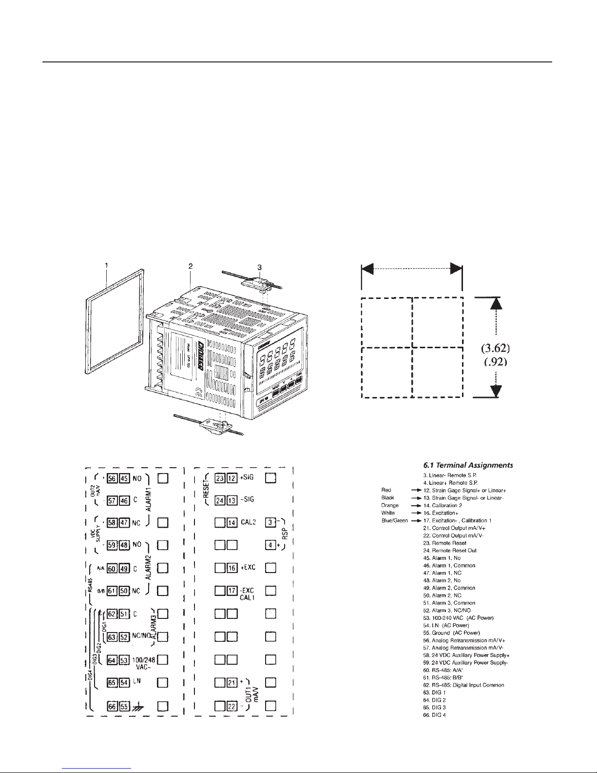
3.1 DIMENSIONAL INFORMATION
Dimensions: 3.78" X 3.78" X 6.01" overall (96mm X 96mm X 143.5mm)
Cutout: 3.62" X 3.62" (92mm X 92mm)
Depth behind panel: 5.04" (128mm)
Weight: 1.43 lbs. (650g)
Page 18
18
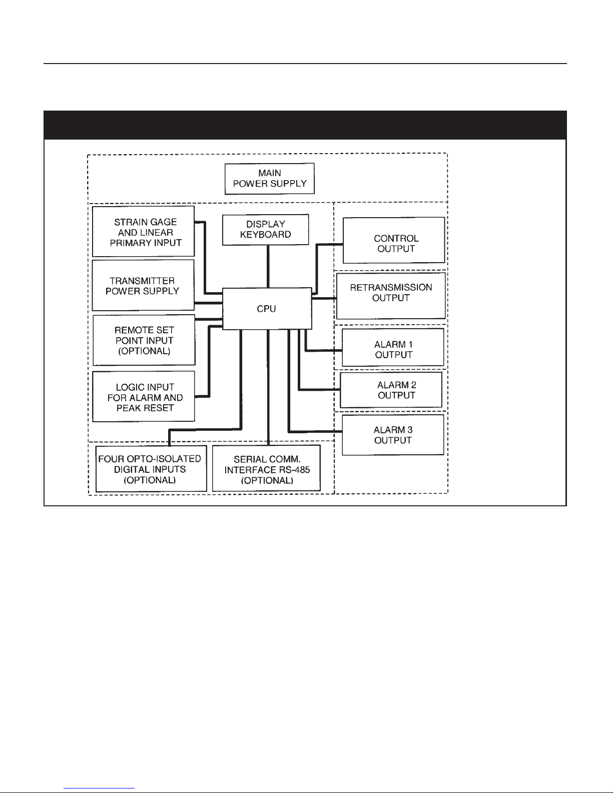
3.2 ATC770 BLOCK DIAGRAM
Fig. 1 ATC770 Electronics Layout Block Diagram
NOTE: Dashed Line represents insulation boundary.
4. MOUNTING AND WIRING
Please refer to Figure 2 for cutout dimensions and clearance requirements. Locate the two mounting
brackets packed with the instrument and have them available.
1. Remove instrument from case. To accomplish this, spread the two locking tabs located on either
side of the case . The instrument will move forward past the locked position. Grasp the bezel
and slide the instrument from the case. Depending on the options chosen, you may find that
one or two boards appear to be loosely mounted. This patent-pending design allows the
instrument to be removed from the case without having to overcome the friction of all terminals
on all boards at one time. Initially the CPU board and alarm board will be released, followed by
the I/O and digital communication boards.
Page 19
ATC770 Microprocessor-Based Pressure/Process Controller 19
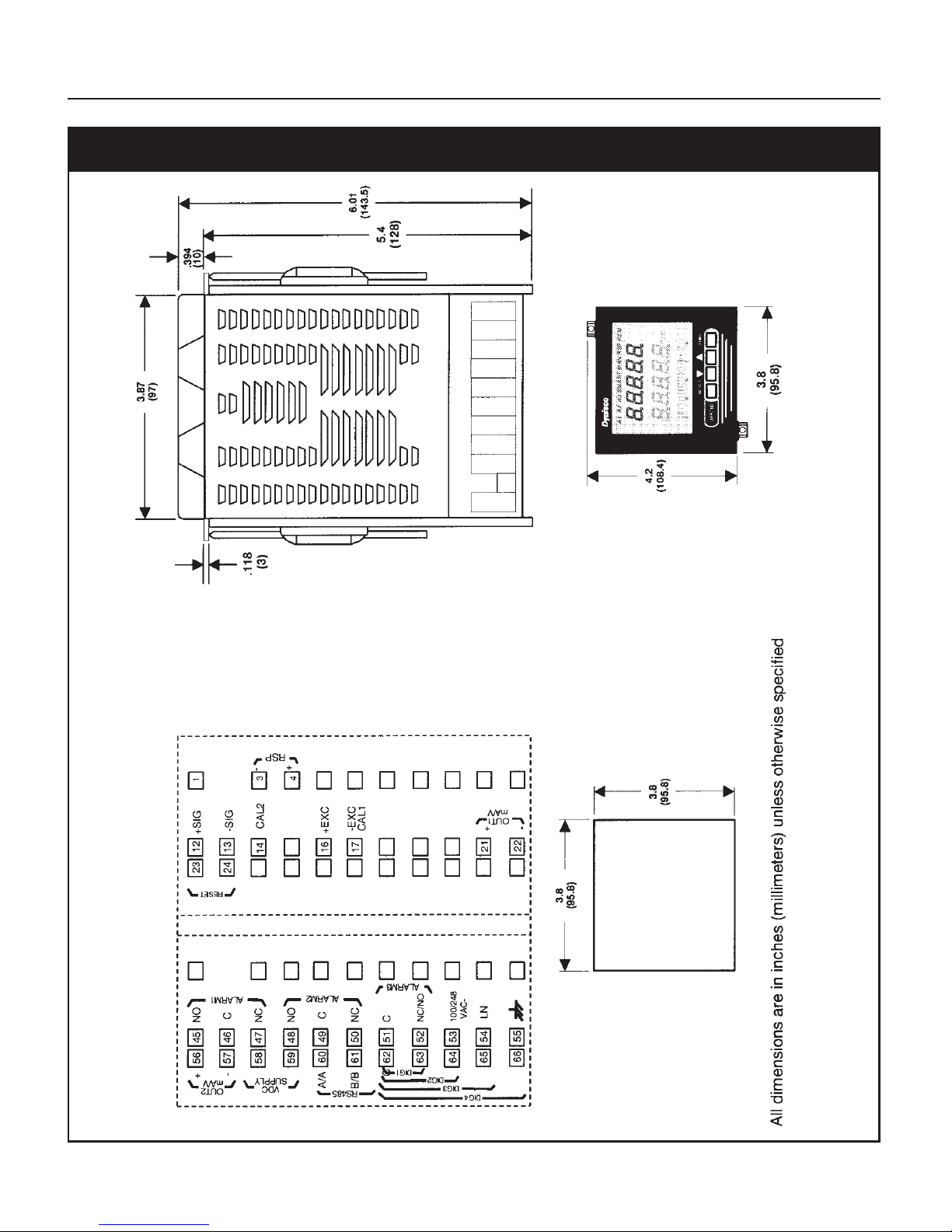
Fig. 2 ATC770 Outline Drawing
Page 20

20
2. Slide the instrument case into the cutout, being sure that it is right-side-up (terminal 1 at the
top). Attach the panel mounting hardware at diagonally opposite sides of the top and bottom of
the case, tightening the threaded rod until the case is secure against the panel.
3. Carefully slide the instrument back into its case, until the locking tabs have engaged. An audible
click will be heard as each tab engages.
4. Refer to the model number to determine the hardware and options included as part of your unit.
Please refer to Section 4.1 for the terminal assignments. Terminals are accessed by opening the
terminal covers from the side with the “OPEN” legend.
NOTE 1:
The ATC770 is equipped with screw terminals, and no connectors are necessary when wiring the
unit
NOTE 2:
When wiring the alarms, wire to the Common and NO (normally open) terminals to maintain a failsafe configuration. Remember to configure the software for failsafe operation.
Fail-safe denotes a situation where the alarms relay coils are activated in a no-alarm situation. As the
relay coil is energized, terminals that are normally open are closed and can cause completion of a
circuit when used as an interlock. Should the alarm threshold be exceeded, OR should power be
lost to the instrument the contacts will open, and the circuit will be broken. If the alarm is a latching
alarm, it will require an external reset signal to be activated again.
If the alarm is used to provide a contact to an alarm device (light, buzzer, etc.), when the threshold
is exceeded, wiring should be to the Common and NC (normally closed) terminals. Activation of the
relay coil will cause the contacts to open in a non-alarm situation, and on alarm, or if power is
interrupted to the instrument. If the alarm is a latching alarm, it will require an external reset signal
to be activated again.
NOTE 3: Relay outputs
The contact rating of all outputs is equal to 2A/240 VAC on resistive load.
•To avoid electrical shock, connect power line at the end of the wiring procedure.
•For power connections use No 16 AWG or larger wires rated for at least 75°C.
• Use copper conductors only.
NOTE 4: Power line
Before connecting the instrument to the power line, make sure that the line voltage corresponds to
the description on the identification label.
•To avoid electrical shock, connect power line at the end of the wiring procedure.
•For supply connections use No. 16 AWG or larger wires rated for at least 75°C
• Use copper conductors only
Page 21
ATC770 Microprocessor-Based Pressure/Process Controller 21
• Don’t run input wires together with power cables
•For 24 V DC the polarity need not be observed.
The power supply input is fuse protected by a sub miniature fuse rated T, 1A, 250V.
When the fuse is damaged, it is advisable to verify the power supply circuit. It may be necessary to
send back the instrument to Dynisco for service.
The safety requirements for Permanently Connected Equipment say:
•a switch or circuit-breaker shall be included In the building installation;
• it shall be in close proximity to the equipment and within easy reach of the operator
• it shall be marked as the disconnecting device for the equipment
NOTE 5:
A single switch or circuit breaker can drive more than one Instrument.
•When a neutral line is present, please connect it to terminal 54.
• Protective conductor terminals shall be connected to earth.
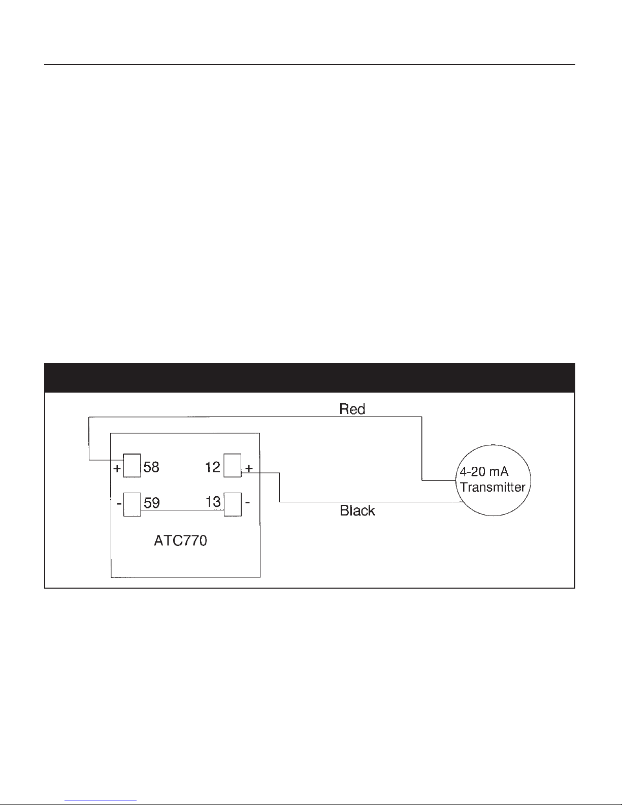
Fig. 3 ATC770 Wiring - 4-20 mA Transmitter Internal 24 VDC Power Supply
Page 22

22
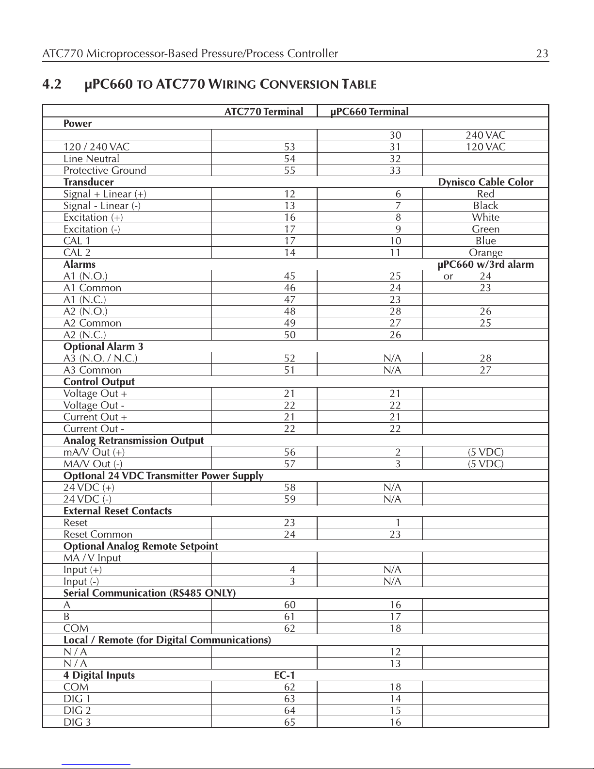
4.1 TERMINAL ASSIGNMENTS
3. Linear - Remote Setpoint Input
4. Linear +
12. Strain Gage Signal + or Linear +
13. Strain Gage Signal - or Linear -
14. Calibration 2 Primary Input
16. Excitation +
17. Excitation -, Calibration 1
21. Main Output mA/V +
22. Main Output mA/V -
23. Remote Reset
24. Remote Reset
45. Alarm 1. NO
46. Alarm 1, Common
47. Alarm 1. NC
48. Alarm 2, NO
49. Alarm 2. Common
50. Alarm 2, NC
51. Alarm 3, Common OPTIONAL
52. Alarm 3. NC/NO
53. 100-240 VAC OR 24 VAC OR 24 VDC (Polarity need not be observed)
54. Line Neutral Line Neutral 24 VDC
55. Protective Ground Protective Ground
56. Retransmission Output, mA/V +
57. Retransmission Output. mA/V -
OPTIONAL
58. 24 VDC Auxiliary Power Supply +
59. 24 VDC Auxiliary Power Supply -
60. RS-485: A/A’
61. RS-485: B/B’ OPTIONAL
62. RS-485: DIG In Common
63. DIG 1
64. DIG 2
OPTIONAL
65. DIG 3
66. DIG 4
Page 23
Page 24

24
5. START-UP PROCEDURE
5.1 CONFIGURATION
The ATC770 is shipped with the hardware jumpers set for the following:
1. Main Input (Pressure) - Strain Gage
2. Main Output - V oltage
3. Secondary Output - Voltage
In addition, the DIP switches controlling the software security lock codes are in the “OFF” positions.
Please ensure that the correct jumper settings for the input(s) and output(s) used in your particular
application are selected. It is necessary only to select the category (e.g. Voltage or Current). The
specific range will be chosen in the software menu.
On special order the ATC770 can be powered from a 24 VAC or VDC supply (not to be confused
with the on-board 24 volt power supply used to power transmitters). If operating with a 24-volt
power supply, connect to terminals 53 and 54 as normal.
5.2 PARAMETERS
The ATC770 parameters are grouped in five sections guarded by three security levels. The more
common parameters are in the first groups, with the higher Group numbers for those parameters an
operator would not normally modify. Each group can be reset to its default value by two keystrokes.
This also resets the parameters of any lower numbered group to default. If GROUP 5 is set to default,
the entire instrument is reset to its default parameters. If a unit does not have a particular option, its
parameters will not appear. For example, an instrument that does not have RS-485 communications
will skip those parameters related to communications. Likewise, if a particular function is turned off,
its other parameters will not appear. For example, if Alarm 2 link
(A2.lNK)
is turned to
OFF
in Group
3, the hysteresis, reset, filter, type, and threshold functions will not appear on screen. Nor will the
alarm appear on the bar graph display.
5.2.1 GETTING READY
Apply power to the cabinet and allow the system to stabilize for about 30 minutes. When the
instrument is turned on, it will go through a self-test during which the front panel will illuminate.
The instrument will then be in the normal display mode showing the value of the main input on the
upper display, usually near zero, and the Output % on the lower display, usually 0.0%. In the event
that no input device is connected, or if the transducer is amplified, the upper display will show
OPEn
, and the bar graph display will be at 100% with the last segment flashing. Turn the power to
the instrument off and connect an input device to the appropriate terminals. Upon turning the
instrument back on, the displays should have a numeric value, close to zero pressure on the
pressure display. Depressing FUNC will go automatically into the GROUP 1 parameters.
Page 25

ATC770 Microprocessor-Based Pressure/Process Controller 25
Successively pressing FUNC will scroll through all the parameters of GROUP 1. The last two
parameters of each group allow the default parameters to be restored, and returns to
GROUP
. If
nonE
is chosen in the group access function, the instrument will return to normal operating mode
after pressing of the FUNC key.
5.2.2 KEYBOARD DESCRIPTION
The keyboard is composed of four push buttons, covered by a silicone protective operator, labeled
▼, ▲, FUNC and A/M.
These keys must be pressed and released to move about in the configure screens. Do not press and
hold a key unless told to do so; simply press the key and release it to advance to the next screen.
The arrow keys ▼ or ▲ may be held down to advance rapidly through the values.
The ▼ is called the “Down Arrow Key”, and is used to decrement or modify the parameter value. In
manual mode it is used to decrement the output value. When pressed for more than 3 seconds in
automatic mode, it used to access and decrease the set point parameter
The ▲ is called the “Up Arrow Key”, and is used to increment or modify the parameter value. In
manual mode it is used to increment the output value. When pressed for more than 3 seconds in
automatic mode, it is used to access and decrease the set point parameter. When pressed for less
than 3 seconds in automatic mode, it used to switch the lower display from set point value,
deviation value, output value (%), output value (RPM) and peak value if enabled.
The FUNC (“function”) key is used to access the parameter to view and acts as an “Enter key” when
a value has been modified.
The A/M key is used to switch the controller from automatic to manual mode (and back again)
when depressed for more than 1 second. When monitoring / modifying control parameters, it is used
to return to the normal display mode without storing the parameter changes.
Pressing ▼ and FUNC together may be used to reset the stored peak value and to reset the alarms.
This function is disabled when the device is controlled by serial link.
Pressing ▼ and A/M together, or the ▲ and A/M may be used to jump to maximum or minimum
parameter values when the instrument is in function mode.
Pressing ▲ and ▼ together, or FUNC and A/M together, may be used on power-up when the
instrument detects a parameter error; the upper display shows
Err
and the lower display shows the
parameter name.
If the wrong parameter is a run-time parameter (i.e. from SP to
RO.TYP
), pressing the ▲ and ▼ push-
buttons will have the instrument load the default parameters for all groups of parameters.
NOTE: All of the actions explained above that require two or more keystrokes must follow the
button pushing sequence exactly.
Page 26

26
5.2.3 OPERATING MODE DESCRIPTION
The FUNC key is used to access the parameters organized in five groups. Use the FUNC
pushbutton to access the Group 1 parameters; the last entry (showing
Group
and
nonE
) is intended
to access the other groups of parameters, or pressing FUNC again returns to the normal display
mode. Each group has its own family of parameters, loosely grouped around the decreasing need to
change the parameters. Each group (except Group 9) also has the ability to load its own default
parameters and the default values of the lower number groups.
To reset a specific group (and lower numbered groups) to the default factory settings, press the
FUNC key until
nonE
and
GROUP
show on the display. Press the ▲ key until the appropriate group
number appears in the upper display. Press the FUNC key to enter the appropriate group. Press the
FUNC key until
DEFLT
shows on the lower display and
OFF
shows on the upper display. Press the
▼ or ▲ key until
ON #
(where # is the Group number). Press the FUNC key to load the factory
parameters for that group (and lower numbered groups; for example selecting Group 5 resets groups
1, 2, 3, 4 and 5).
5.3 SETTING THE INSTRUMENT’S BASIC CONFIGURATION
The example below shows those parameters by group, which will permit an ATC770 to control a
motor. A modification of any other of the default parameters is not needed. Please note in the Value
column, the final values used in your process for future set-up use.
Fig. 4 Basic Parameter Table
Group # Function Mnemonic Choices Default Value
Group 5 Primary Input Selection PI.TYP Str, 0-20, 4-20, 0-5, 0-10 Str
Group 5 Control Output Selection CO.TYP 0-20, 4-20, 0-5 0-10, -10-10 0-10
Group 4 Shunt Calibration SHUNT OFF,On On
Group 4 Shunt Value SHNT% 40.0 TO 100.0% 80.0%
Group 4 Line Frequency LINE.F 50, 60 50
Group 3 Input Full Scale Value PI.FSV 10 TO 99.950 10000
Group 3 Input Low Scale Value PI.LSV ±25% OF FSV 0
Group 3 Input Decimal Point Position PI.DP None, 1,2,3,4 places None
Group 3 Secondary Input T/C Type Sl.TC tc J, tc CA, tc L, tc n tc J
Group 2 Zero Calibration ZERO.C OFF, On, CLEAr OFF
Group 2 Span Calibration SPAN.C OFF, On, CLEAr OFF
Group 2 Type of Automatic Tuning AT.TYP PID, PI PI
Group 2 Self-Tuning SMART OFF, On On
Group 1 Setpoint SP SP.LO to SP.HI SP.LO
5.3.1 SETTING THE SHUNT CALIBRATION:
For transducers and transmitters with a shunt calibration function (internal or external), the various
Page 27

ATC770 Microprocessor-Based Pressure/Process Controller 27
values must be set and the shunt capability enabled. The Shunt Calibration value is a percentage of
the full scale transducer range. If the Shunt Value is supplied as a pressure, it must be converted to
percent.
To enter the Shunt Calibration value, the shunt should first be enabled by pressing the FUNC key
until
nonE
and
GROUP
show on the display. Press the ▲ key until 4 shows in the upper display.
Press the FUNC key until the lower displa y shows
SHUNT
. Press the ▼ or ▲ key until the upper
display shows the ON. Press the FUNC key to set the value and move to the next parameter, Shunt
%
(SHNT.%)
. Press the ▼ or ▲ key until the upper display shows the appropriate percentage for the
shunt value (normally 80%). Once the percentage value is set, press the FUNC key to set the value
and press the A/M key to go back to the active display.
5.3.2 SETTING THE LOGIC INPUT CONFIGURATION (IF SUPPLIED):
If the unit does not have the logic input option, skip to Section 5.3.4.
NOTE: Alarm and peak reset is only available when A/M in Group 1 is set to Local.
The Logic Input can be off, can be set to function as an alarm reset, a peak reset, or it can reset both.
To verify this parameter or to change it, press the FUNC key until
nonE
and
GROUP
show on the
display. Press the ▲ key until 4 shows in the upper display. Press the FUNC key until the lower
display shows
LI.TYP
. Press the ▼ or ▲ key until the upper display shows the correct selection:
OFF
,
AL
- alarms reset, P - Peak reset or
AL-P
). Press the FUNC key to set the value and move to the next
parameter, or press the A/M key to go back to the active display.
5.3.3 SETTING THE LOGIC INPUT STATUS (IF SUPPLIED)
The Logic Input Status can be set to Open or Closed as the active state. To verify this parameter or to
change it, press the FUNC key until
nonE
and
GROUP
show on the display. Press the ▲ key until
4
shows in the upper display. Press the FUNC key until the lower display shows
LI.STS
. Press the ▼ or
▲ key until the upper display shows the correct selection:
CLOSE
, or
OPEn
. Press the FUNC key to
set the value and move to the next parameter, or press the A/M key to go back to the active display.
5.3.4 SETTING THE STATUS OF AUTO/MANUAL SELECTION (IF SUPPLIED)
If the unit does not have the Digital Input option, skip to Section 5.3.5.
NOTE: Remote Auto/Manual is only available when Auto/Manual in Group 1 is set to CNCT.
The ATC770 Pressure/Process controller has four digital inputs that can switch between Manual and
Automatic control (DIG 1), increase (DIG2) or decrease (DIG3) the control output value and switch
from Automatic to Manual setting the control output to zero (DIG4). The Auto/Manual Selection
parameter determines the status of the communication protocol. Select
LoCAL
to use the front push
buttons or RS-485 to control switching from manual to automatic, or Select
CnCt
to use external
means to control switching from manual to automatic.
Page 28

28
NOTE: A dry contact switch or relay must be fitted between terminal 62 (Common) and terminal 63
(Digital Input 1 Remote AUTO/MAN (DIG1)) to enable the use of Digital Input 2 (DIG2) and
3 (DIG3) (Control output value increase and decrease).
To verify this parameter or to c hange it, press the FUNC key until the lower display shows
A/M
.
Press the ▼ or ▲ key until the upper display shows the correct value (
LoCAL
or
CnCt
). Press the
FUNC key to set the value and move to the next parameter, or press the A/M key to go back to the
active display .
5.3.5 SETTING PEAK DETECTION
The Peak Detection can be either set to OFF, the default value of HIGH, or to LOW. To verify or
change this parameter, press the FUNC key until
nonE
and
GROUP
show on the display. Press the
▲ key until 4 shows in the upper display. Press the FUNC key until the lower display shows
PEAK
.
Press the ▼ or ▲ key until the display shows the correct value (
OFF, HI
, or LO). Press the FUNC key
to set the value and move to the next parameter, or press the A/M key to go back to the active
display.
5.3.6 SETTING THE LINE FREQUENCY
The Line Frequency default value is 50 Hz. To verify this parameter or to change to 60 Hz, press the
FUNC key until
nonE
and
GROUP
show on the display. Press the ▲ key until 4 shows in the upper
display. Press the FUNC key until the lower display shows
LINE.F
. Press the ▼ or ▲ key until the
upper display shows the correct frequency. Press the FUNC key to set the value. Press the FUNC
key to set the value and move to the next parameter, or press the A/M key to go back to the active
display.
5.3.7 SETTING THE DISPLAY FILTER
Filtering is an electrical method of averaging the displayed values over a period of time to arrive at a
more legible display. Filtering helps to eliminate short duration transients and spikes that may cause
false or spurious readings.
To change or view the Display and Controller input Filter, press the FUNC key until
nonE
and
GROUP
show on the display. Press the ▲ key until 2 shows in the upper display. Press the FUNC
key until the lower display changes to
AT.FL
. Using the ▼ or ▲ keys, select the amount of filtering
desired, from none
(OFF)
to five seconds. When finished, press the FUNC key to lock in the value
and advance to the next parameter, or press the A/M key to go back to the active display.
5.4 SETTING THE REMOTE SET POINT INPUT (OPTIONAL)
The Remote Set Point allows the user to control the setpoint from a remote voltage or current source
(0-10 VDC, 0-20 mA or 4-20 mA sources), and to select either the keyboard or the remote power
source as control device.
Page 29

ATC770 Microprocessor-Based Pressure/Process Controller 29
5.4.1 SETTING THE REMOTE SET POINT INPUT VOLTAGE OR CURRENT
To change or view the Remote Set Point selection parameter, press the FUNC key until
nonE
and
GROUP
show on the display. Press the ▲ key until 5 shows in the upper display. Press the FUNC
key until the lower display changes to
RI.TYP
. Using the ▼ or ▲ keys, select the voltage or current
input desired: (0-10 VDC, 0-20 mA or 4-20 mA sources or
OFF
). When finished, press the FUNC
key to lock in the value. To select the jumper setting necessary, see Figure 5 below:
Fig. 5 ATC770 Board Location
Page 30

30
Fig. 6 Remote Set Point Jumper Location, Board E
Page 31

ATC770 Microprocessor-Based Pressure/Process Controller 31
5.4.2 SETTING THE REMOTE SET POINT INPUT FAILSAFE MODE
The Remote Set Point Failsafe parameter sets the value of the control signal in the event of a failure
of the Remote Set Point signal. The Default value is
Low
.
To change or view the Remote Set Point Failsafe Mode, press the FUNC key until
nonE
and
GROUP
show on the display. Press the ▲ key until 4 shows in the upper display. Press the FUNC key until
the lower display changes to
RI.IFS
. Using the ▲ or ▼ keys, select the desired setting: LO or HI.
When finished, press the FUNC key to lock in the value.
5.4.3 SETTING THE REMOTE SET POINT LIMITS
The Remote Set Point can be limited to a specific output both on the low and the high side. Either
value can be set to the Primary Input Full Scale Value.
To set the Remote Set Point Low parameter, press the FUNC key until
nonE
and
GROUP
show on
the display. Press the ▲ key until 3 shows in the upper display. Press the FUNC key until the lower
display shows
SP.LO
. Using the ▲ or ▼ keys, select the desired value from the default 0 to the
Primary Input Full Scale Value
(PI.FSV)
. When finished, press the FUNC key to lock in the value and
advance to the next variable, the Remote Set Point High parameter
SP.HI
.
To set the Remote Set Point High parameter, press the ▲ or ▼ keys, select the desired value from the
default
PI.SFV
to the value selected in
SP.LO
. When finished, press the FUNC key to lock in the
value and advance to the next parameter, or press the A/M key to go back to the active display.
5.4.4 SETTING THE LOCAL REMOTE SET POINT SELECTION
Either the Remote Set Point or local control can be used to start the process. To select the start mode,
press the FUNC key until
nonE
and
GROUP
show on the display. Press the ▲ key until 2 shows in
the upper display. Press the FUNC key until the lower display shows
LR.SP
. Using the ▲ or ▼ keys,
select the desired value from the default
LOC
(local) to
rEn
(remote). When finished, press the
FUNC key to lock in the value. Press the A/M key to go back to the active display. The selection of
LR.SP
is stored in nonvolatile memory, and this selection will be saved even if the instrument has
been totally shut down. On start-up, the
LR.SP
status will be restored as set.
6. CONFIGURATION
6.1 PRIMARY INPUT SETUP
6.1.1 SETTING THE PRIMARY INPUT TYPE FOR A STRAIN GAGE TRANSDUCER
If you have an amplified transducer, or other amplified input, skip to Section 6.1.2, otherwise, if
using a
Dynisco
transducer, the model number of the transducer will designate its own electrical
output. For example, in plastic melt applications, the PT462E-5M-6/18 or TPT432A-10M-6/18 have
Page 32

32
a strain gage (0-3.33 mV/V full scale) signal output. Amplified units have a number where the strain
gage units have a letter (E or A). The PT4624-5M-6/18 has a 4-20 mA signal output; the PT4625-5M6/18 has a 0-5 VDC signal output, while PT4626-5M-6/18 has a 0-10 VDC signal output. In
Industrial applications, amplified units have a middle or end number of 4, 5, or 6. The S840-000-1C
has a 4-20 mA signal output; the PT150-7.5M has a 0-5 VDC signal output, while PT276-5M has a
0-10 VDC signal output.
The ATC770’s default setting is strain gage input. To verify that the input is set for strain gage, press
the FUNC key until
nonE
and
GROUP
show on the display. Press the ▲ key until 5 shows in the
upper display. Press the FUNC key and the upper display should show
Str
while the lower display
shows
PI.TYP
. If not, press the ▲ or ▼ key until the upper displa y changes to
Str
(for strain gage).
Press the FUNC key to set the value. Press the A/M key to return to the active display. Remember to
change the jumper settings to correspond to the proper input as shown in Figure 7 for board location
and Figure 8 for amplified input jumpers.
Fig. 7 ATC770 Board Location
Page 33

ATC770 Microprocessor-Based Pressure/Process Controller 33
Fig. 8 Input/Output Jumper Location
6.1.2 SETTING THE SHUNT CALIBRATION FOR STRAIN GAGE TRANSDUCERS
AND
AMPLIFIED TRANSMITTERS
The Dynisco strain gage transducers and amplified transmitters (if so equipped) have an internal
shunt to allow the ATC770 to set the internal scaling for correct display. To Access the Shunt
Calibration parameter, press the FUNC key until
nonE
and
GROUP
show on the display. Press the
▲ key until 4 shows in the upper display. Press the FUNC key and the upper display will show
OFF
while the lower displa y shows
SHUNT
. Press the ▲ or ▼ key until the upper display changes to the
ON
. Press the FUNC key to set the value and move to the next Shunt par ameter.
The upper display will show
80.0
while the lower display shows
SHNT%
. In most cases, the
Page 34

34
Dynisco transducers have an 80% shunt value so no changes need be made. However, some
transducers and strain gages have shunt values that may range from 40% to 100%. If so, press the ▲
or ▼ key until the upper display changes to the correct values. Press the FUNC key to set the value.
Press the A/M key to go back to the active display.
6.1.3 SETTING THE PRIMARY INPUT TYPE FOR AN AMPLIFIED TRANSMITTER
If using a voltage or current output transducer, the model number of the transducer will designate its
own electrical output. For example, a PT4624-7.5M-6/18 or an S840-000-10M has an amplified
signal output. In plastic melt applications, amplified units have a number where the strain gage units
have a letter (E or A). The PT4624-7.5M-6/18 has a 4-20 mA signal output; the PT4625-7.5M-6/18
has a 0-5 VDC signal output, while PT4626-7.5M-6/18 has a 0-10 VDC signal output. In Industrial
applications, amplified units have a middle or end number of 4, 5, or 6. The S840-000-1C has a 420 mA signal output; the PT150-7.5M has a 0-5 VDC signal output, while PT276-5M has a 0-10
VDC signal output.
If you have a strain gauge transducer, load cell, or other Wheatstone bridge device, see Section
6.1.1.
The Instrument’s default setting is strain gage input. To select another input for a transmitter or to use
another process instrument, such as humidity sensors, position sensors, etc., press the FUNC key
until
nonE
and
GROUP
show on the display. Press the ▲ key until 5 shows in the upper display.
Press the FUNC key and the lower display will show
PI.TYP
. Press the ▲ or ▼ key until the upper
display changes to the correct value (
0-20
for 0-20 mA linear input,
4-20
for 4-20 mA current loop
input,
0-5
for 0-5 VDC linear input, and
0-10
for 0-10 VDC linear input). Press the FUNC key to set
the value. Press the A/M key to go back to the active display.
Remember to change the jumper settings to correspond to the proper input as shown in Figure 7 for
board location and Figure 9 for amplified input jumpers.
Page 35

ATC770 Microprocessor-Based Pressure/Process Controller 35
Fig. 9 Input Selection J84 for Amplified Input
6.1.4 SETTING THE PRIMARY INPUT FULL-SCALE VALUE
The model number of the transducer or transmitter will designate the full-scale pressure capability.
For example, model number TPT432A-5M-6/18 indicates that the full-scale pressure is 5,000 (5M),
while the PT150-5C indicates that the full-scale pressure is 500 (5C). Since the default value in the
instrument is 10,000 full scale, the input full scale value must be changed to 5,000 (or 500). Note
that there are no units here, it can be psi, bar, mPa, kg/cm2 or any engineering unit; the magnitude
is all that is important.
To set the full-scale value, press the FUNC key until
nonE
and
GROUP
show on the display. Press
the ▲ key until 3 shows in the upper display. Press the FUNC key and the upper display will show
10000
while the lower display shows
PI.FSV
. Hold the ▲ or ▼ key until the upper display changes
to
5000
(or whatever the full-scale value of the primary input may be). Press the FUNC key to set
the value. Check that the next display reads 0 in the upper display and
PI.LSV
in the lower display; if
not, set to zero with the arrow keys and press FUNC to lock in the value. Finally, press the A/M key
to go back to the active display. Similarly, if the full-scale pressure is 350 Bar (3.5CB), set
PI.FSV
to
350.
Page 36

36
6.1.5 SETTING THE PRIMARY INPUT LOW-SCALE VALUE
For applications where a low scale value is non-zero, the Instrument can provide a low scale value
of ±25% of the full scale value.
To set the low-scale value, press the FUNC key until
nonE
and
GROUP
show on the display. Press
the ▲ key until 3 shows in the upper display. Press the FUNC key and the upper display will show a
value while the lo wer display shows
PI.FSV
. Press the FUNC key and the upper display will sho w
0
while the lower displa y shows
PI.LSV
. Hold the ▼ or ▲ key until the upper displa y changes to
whatever the low-scale value of the primary input may be. Press the FUNC key to set the value.
Finally, press the A/M key to go back to the active display.
6.1.6 SETTING THE PRIMARY INPUT DECIMAL PLACE
To set the decimal place, press the FUNC key until
nonE
and
GROUP
show on the display. Press the
▲ key until 3 shows in the upper displa y. Press the FUNC key until the lower display shows
PI.DP
.
Press the ▼ or ▲ key until the upper display shows the correct decimal place location. For example,
a 350 Bar unit may show 350.0 for decimal place setting. Press the FUNC key to set the value.
Finally, press the A/M key to go back to the active display.
6.1.7 SETTING THE PRIMARY INPUT FAILSAFE MODE
The Primary Input Failsafe Mode is nothing more than a safety mechanism that tells the instrument
what to do in the event of a loss of the primary signal. If the system is set up to shut down the
process in a high alarm condition, the Primary Input Failsafe parameter can set the value of the
primary input to full scale if it looses the primary signal. If the system is set up to shut down the
process in a low alarm condition, the Primary Input Failsafe parameter may set the value of the
primary input to low scale if it looses the primary signal. The default Primary Input Failsafe Mode is
to set the value to full scale high.
To set the Primary Input Failsafe Mode, press the FUNC key until
nonE
and
GROUP
show on the
display. Press the ▲ key until 4 shows in the upper display. Press the FUNC key until the lower
display shows
PI.IFS
. Press the ▼ or ▲ key until the upper display shows the correct mode, either
HI
or Lo. Press the FUNC key to set the value. Finally, press the A/M key to go back to the active
display.
6.2 SETTING THE ALARMS
All Alarms supplied with the Instrument can be linked to the actual pressure value, a pre-selected
band about that pressure value, deviation from setpoint, or turned off. The alarms are capable of
being set as High Level Alarms or Low Level Alarms, and may operate in either
Failsafe
or
Direct
condition.
Failsafe
means that in the event of power failure to the Instrument, the Alarm will activate. Use this
feature on a shutdown alarm. Please note that in a proper operating condition in Failsafe mode, the
Page 37

ATC770 Microprocessor-Based Pressure/Process Controller 37
Normally Closed Contact are held OPEN, while the Normally Open contacts are held CLOSED. On
power failure, they are released.
On start-up, a Low Alarm may cause the unit to go into an undesired alarm condition prior to
reaching running conditions. This Alarm can be masked so that the Low Alarm will be deactivated
until it has gone above the alarm value for the first time. It will then operate as a normal low alarm.
The default values for Alarm 1 are: an inhibited low alarm set at 5% of full scale, linked to the
primary process input, 0.4 second filtering, 1% hysteresis, automatic reset and failsafe mode. Each
alarm may be set to 110% of full scale.
The default values for Alarm 2 are: high alarm at 60% of full scale, linked to the primary process
input, 0.4 second filtering, 1% hysteresis, automatic reset, and failsafe mode.
The default values for Alarm 3 are: high alarm at 80% of full scale, linked to the primary process
input, 0.4 second filtering, 1% hysteresis, automatic reset, and failsafe mode.
Set the Alarm parameters before setting the alarm value. If the alarm parameters have already been
set, set the alarm values as described in Section 6.2.7.
6.2.1 SETTING WHAT THE ALARM WILL MONITOR (ALARM INPUT CHANNEL LINK)
The Alarm 1 Input Channel Link defaults to the primary process input. To check or change this value
press the FUNC key until
nonE
and
GROUP
show on the display. Press the ▲ key until 3 shows in
the upper display. Press the FUNC key until
A1.LNK
shows in the lower display. Select the choice
desired by pressing the ▼ or ▲ keys. The choices are:
OFF
, (disabled), a process alarm (on achieving
a specific pressure)
Proc
, a band alarm around a specific pressure range
bAnd
, or a deviation alarm
from a specific pressure
dEu
. Press the FUNC key to lock in the value and advance to the next
parameter. Similarly, you may configure Alarm 2
(A2.LNK)
and Alarm 3
(A3.LNK)
.
6.2.2 SETTING ALARM TYPE
A high alarm will activate when a set point is exceeded. A low alarm will activate whenever the
value falls below a set point (including startup). An inhibited low alarm must exceed the low alarm
set point before it is enabled. Then it will work like a low alarm. This is ideal on startup.
The default alarm type for Alarm 1 is high. To check or change this value press the FUNC key until
nonE
and
GROUP
show on the display. Press the ▲ key until 3 shows in the upper display. Press the
FUNC key until
A1.TYP
shows in the lower display. Using the ▼ or ▲ keys, select HI for high level
alarm, LO for low level alarm or
Inhib
for a low level alarm with mask at start-up. Press the FUNC
key to lock in the value and advance to the next parameter. If finished, press A/M to return to the
operating screen. Similarly, you may configure Alarm 2
(A2.TYP)
and Alarm 3
(A3.TYP)
.
Page 38

38
6.2.3 SETTING THE FILTERING FOR ALARMS
Filtering is an electrical method of averaging the input values over a period of time to arrive at a
smoother curve. This helps to eliminate short duration transients and spikes which can cause alarms,
but which may cause false or spurious readings.
The Alarm filter default is 0.4 seconds of filtering. To change this value, press the FUNC key until
nonE
and
GROUP
show on the display. Press the ▲ key until 2 shows in the upper display. Press the
FUNC key until the lower display c hanges to
A1.FL
. Using the ▼ or ▲ keys, select the amount of
filtering desired, from none
(OFF)
to five seconds. When finished, press the FUNC key to lock in the
value and advance to the next parameter. If finished, press A/M to return to the operating screen.
Similarly, you may configure Alarm 2
(A2.FL)
and Alarm 3
(A3.FL)
.
6.2.4 SETTING THE HYSTERESIS FOR ALARM
Hysteresis is used to describe the amount that the reading must drop below the alarm point (in a
high alarm) or must rise above the alarm point (in a low alarm) to clear the alarm condition. This
helps to eliminate short duration alarms when operating near the alarm condition. To change or
view this value, press the FUNC key until
nonE
and
GROUP
show on the display. Press the ▲ key
until 4 shows in the upper display. Press the FUNC key until the lower display changes to
A1.HYS
.
The values for hysteresis can range from .1% to 10.0%. Press the ▼ or ▲ keys until the upper
display changes to the desired value. Press the FUNC key to lock in the value and advance to the
next parameter, or press A/M to return to the operating screen. Similarly, you may configure Alarm
2
(A2.HYS)
and Alarm 3
(A3.HYS)
.
6.2.5 SETTING THE RESET MODE FOR ALARMS
The Alarm Reset Mode determines if the alarm resets itself once the alarm condition is been
corrected, or whether the operator must press a button to reset the alarm. The Alarm Reset Mode
default is automatic reset once the alarm has cleared. To change or view this value, press the FUNC
key until
nonE
and
GROUP
show on the display. Press the ▲ key until 4 shows in the upper display.
Press the FUNC key until the lower display c hanges to
A1.RES
. The value for reset mode is either
Auto
for automatic reset, or
LAtCH
for manual reset. Press the ▼ or ▲ keys until the upper display
changes to the desired value.
Press the FUNC key to lock in the value and advance to the next parameter, or press A/M to return
to the operating screen. Similarly, you may configure Alarm 2
(A2.RES)
and Alarm 3
(A3.RES)
.
6.2.6 SETTING THE FAILSAFE MODE FOR ALARMS
The Alarm Failsafe Mode determines how the alarms react in the event of a power failure to the
ATC770. In the failsafe mode, the alarms will activate in the event of power loss. In non-failsafe
mode they cannot activate on power loss. The Alarm Failsafe default is failsafe mode. To change this
value, press the FUNC key until
nonE
and
GROUP
show on the display. Press the ▲ key until
4
shows in the upper display. Press the FUNC key until the lower display changes to
A1.FSM
. The
Page 39

ATC770 Microprocessor-Based Pressure/Process Controller 39
options for failsafe mode are either FS for failsafe mode, or
nFS
for non-failsafe mode. Press the ▼ or
▲ keys until the upper display changes to the desired value. Press the FUNC key to lock in the
value and advance to the next parameter. Similarly, you may configure Alarm 2
(A2.FSM)
and Alarm
3
(A3.FSM)
.
Carefully consider the Alarm wiring: For failsafe operation the alarm contacts must be wired
differently to have operation as expected. The ATC770 energizes the contact relay during failsafe
operation. This means the NO contact will be held CLOSED during normal operation. In the event
of an alarm or the loss of power to the ATC770, the relay will be de-energized and will then open.
The same holds true for a NC contact. It will be held OPEN during normal operation. In the event of
an alarm condition or the loss of power to the ATC770, the relay will be de-energized and will then
close. In non-failsafe operation the reverse is true, in that a NO acts as a NO and a NC acts as an
NC.
6.2.7 SETTING THE ALARMS VALUE
The Alarm 1Threshold Values, is the value beyond which the Alarm will activate (i.e. the threshold).
Alarm 1 is set in the same engineering units that the Full Scale Value uses. To change or view this
value when in the operating screen, press the FUNC key, when in the main screen, and the lower
display will c hange to
AL1
with the threshold value in the upper display . Press the ▼ or ▲ keys until
the upper display changes to the desired value. Press the FUNC key to lock in the value and
advance to the next parameter, or press A/M to return to the operating screen. Similarly, you may
configure Alarm 2
(AL2)
and Alarm 3
(AL3)
.
6.2.8 SETTING THE ALARMS MASK RESET TYPE
The Alarm 1 Mask Reset may only be used on alarms configured as inhibited low alarms on startup.
It prevents the alarm from activating (masks the alarm) until the value of the primary input exceeds
the alarm value. To change or view this value when in the operating screen, press the FUNC key
until the lower display changes to
AL.MSK
with
OFF
in the upper display. Press the ▼ or ▲ keys
until the upper display changes to
rESEt
. Press the FUNC key to lock in the value and advance to
the next parameter, or press A/M to return to the operating screen. You may similarly configure
Alarm 2 or 3.
6.3 RETRANSMISSION OUTPUT SETUP
This ATC770 has a retransmission output which can send a signal to a recorder or some other device
that can accept a voltage or current signal.
6.3.1 SELECTION THE RETRANSMISSION OUTPUT
The Retransmission Output Type sets the output to specific voltages or currents. The available
outputs are 0-20 mA, 4-20 mA, 0-10 VDC, -10 to +10 VDC, and 0-5 VDC. To change or view this
value, press the FUNC key until
nonE
and
GROUP
show on the display. Press the ▲ key until
5
shows in the upper display. Press the FUNC key until the lower display changes to
RO.TYP
, and the
Page 40

40
upper display shows the selected type. Press the ▼ or ▲ keys until the upper display changes to the
desired value. Then press the FUNC key to lock in the value. Press A/M to return to the operating
screen.
Next, select the jumper setting necessary. See Figure 10 below:
Fig. 10 Input/Output Jumper Location
Page 41

ATC770 Microprocessor-Based Pressure/Process Controller 41
6.3.2 SETTING THE RETRANSMISSION OUTPUT RANGE
To change or view the Retransmission Output Range Low, press the FUNC key until
nonE
and
GROUP
show on the display. Press the ▲ key until 3 shows in the upper display. Press the FUNC
key until the lower display changes to
RO.LO
. Press the ▼ or ▲ keys until the upper display
changes to the desired value. The value may be anything from 0 to the primary input full scale value,
PI.FSV
. This can act as a scale expander; i.e. if the system has a 10,000 psi transducer but usually
runs from 3,000 to 6,500, the
RO.LO
can be set to 2,500 so that the output at 2,500 psi is 0. Once
the desired value is set, press the FUNC key to lock in the value and advance to the next parameter
the Retransmission Output Range High
RO.HI
.
6.3.3 SETTING THE RETRANSMISSION OUTPUT RANGE HIGH
If
RO.HI
does not appear from the previous step, press the FUNC key until
nonE
and
GROUP
show
on the display. Press the ▲ key until 3 shows in the upper display. Press the FUNC key until the
lower display changes to
RO.HI
.
Once
RO.HI
appears, press the ▼ or ▲ keys until the upper display changes to the desired value.
The value may be anything from 0 to the primary input full scale value,
PI.FSV
. This can act as a
scale expander; i.e. if the system has a 10,000 psi transducer but usually runs from 3,000 to 6,500,
the
RO.HI
can be set to 7,500 so that the output at 7,500 psi is full scale voltage or current. Once
the desired value is set, press the FUNC key to lock in the value and advance to the next parameter,
or press A/M to return to the operating screen.
6.3.4 SETTING THE RETRANSMISSION OUTPUT FILTER
Filtering is an electrical method of averaging the output values over a period of time to arrive at a
smoother curve. This helps to eliminate short duration transients and spikes that may cause false or
spurious readings.
To change or view the Retransmission Output Filter, press the FUNC key until
nonE
and
GROUP
show on the display. Press the ▲ key until 2 shows in the upper display. Press the FUNC key until
the lower display changes to
RO.FL
. Using the ▼ or ▲ keys, select the amount of filtering desired,
from none
(OFF)
to five seconds. When finished, press the FUNC key to lock in the value. Press
A/M to return to the operating screen.
6.4 SETTING THE CONTROL OUTPUT
The control output is opto-isolated from the CPU input and output circuits. The types of Control
Outputs available are jumper and keyboard selectable between various voltages and currents.
6.4.1 SETTING THE CONTROL OUTPUT VOLTAGE OR CURRENT
The control output can have a 0-5 VDC, a 0-10 VDC, a -10 to +10 VDC, a 4-20 mA or a 0-20 mA
output. The range of output is selected from the keyboard, but the type of output must be selected by
Page 42

42
using jumpers. To select the voltage or amperage range, press the FUNC key until
nonE
and
GROUP
show on the display. Press the ▲ key until 5 shows in the upper display. Press the FUNC
key until the lower display sho ws
CO.TYP
. Using the ▼ or ▲ keys, select the desired value:
0-5
(VDC),
0-20
(mA),
4-20
(mA),
0-10
(VDC), or
-10.10
(VDC). When finished, press the FUNC key to
lock in the value and A/M to return to the main screen.
Next, select the jumper setting necessary. See Figure 11 below:
Fig. 11 Input/Output Jumper Location
Page 43

ATC770 Microprocessor-Based Pressure/Process Controller 43
6.4.2 MAKING THE CONTROL OUTPUT DIRECT/REVERSE SELECTION
The input signal can cause the control output to either increase or decrease with an increasing or
decreasing input signal. The table below shows the value of Direct/Reverse Control Output selection
(CO.D/R)
. The first digit shows the relationship between the input signal and the displayed output
value
(OUT%)
. The last digit shows the relationship between the displayed output signal and the
output value voltage or current.
Value Input Signal Displayed Output Control Output
r d
0-100 (increase) 100-0 (decrease) 100-0 (decrease)
r r
0-100 (increase) 100-0 (decrease) 0-100 (increase)
d d
0-100 (increase) 0-100 (increase) 0-100 (increase)
d r
0-100 (increase) 0-100 (increase) 100-0 (decrease)
The default value is
r d
(Reverse-Direct), or decreasing the Displayed and Control outputs with
increasing signal.
6.4.3 SETTING THE CONTROL OUTPUT LIMIT
The Control Output Signal can be limited to a specific percentage value to prevent downstream
problems. To set the Control Output Limiter parameter
(CO.MAX)
, press the FUNC key until
nonE
and
GROUP
show on the display. Press the ▲ key until 4 shows in the upper display. Press the
FUNC key until the lower display shows
CO.MAX
. Using the ▼ or ▲ keys, select the desired value
from 10.0 to 100.0%. When finished, press the FUNC key to lock in the value and A/M to return to
the main screen.
6.4.4 SETTING THE CONTROL OUTPUT MANUAL MORE INDICATION
This parameter is used to select how the controller shows the output value in manual mode: either
in the range of 0-100%, or scaled with the
CO.HI
and
CO.LO
parameters. The default value is 0-
100%. To confirm or change this value, press the FUNC key until
nonE
and
GROUP
show on the
display. Press the ▲ key until 4 shows in the upper display. Press the FUNC key until the lower
display shows
CO.MMI
. Using the ▼ or ▲ keys, select either
100.0%
or
rPn
(for RPM indication).
When finished, press the FUNC key to lock in the value, and A/M to return to the main screen.
6.4.5 SETTING THE CONTROL OUTPUT DISPLAY
The Control Output Display can be changed to reflect RPM or some other external parameter.
However, since this is arbitrary and will be tuned to a specific device, it is recommended to skip this
section and use the defaults.
To change the Control Output Range Low
(CO.LO)
from the standard 0 value, press the FUNC key
until
nonE
and
GROUP
show on the display. Press the ▲ key until 3 shows in the upper display.
Press the FUNC key until the lower display shows
CO.LO
. Using the ▼ or ▲ keys, select the
Page 44

44
desired value from -10000 to the
CO.HI
value. (if no
CO.HI
value has been set, you may need to
return to this step. When finished, press the FUNC key to lock in the value. The lower display will
show
CO.HI
, and the upper display will show the default value (100.0). Using the ▼ or ▲ keys,
select the desired value from 0 to 10000 for the
CO.HI
value. When finished, press the FUNC key
to lock in the value. The lower display will show
CO.DP
, for the decimal point position, and the
upper display will show the default value (100.0). Using the ▼ or ▲ keys, select the desired decimal
point position. When finished, press the FUNC key to lock in the value, and A/M to return to the
main screen.
6.5 SETTING THE SECURITY CODES
The security code setting is accessible by setting an internal dip switch (see Figure 12 below). There
are three Security levels. When each level has been assigned a code access to the parameters will be
available as follows:
• Level A: Allows access to parameters in Group 1 Only
• Level B: Allows access to parameters in Groups 1 and 2 Only
• Level C: Allows access to parameters to all Groups 1 - 5
To enter the security mode, remove the instrument form its case and reconfigure the internal dip-
switch settings to the Security Mode by placing SW1 and SW2 in the ON position.
Fig. 12 CPU Board DIP Switch Locations
When the instrument is re-inserted into its case, the upper display will show
CodE
and the lower
display will show
ATC
.
Page 45

ATC770 Microprocessor-Based Pressure/Process Controller 45
6.5.1 SETTING THE SECURITY CODE FOR LEVEL A
To view or change the security code, press the FUNC key and the lower display changes to
CODE.A
. The upper display shows 0, which indicates no security, and 1 means all parameters
related to levels A, B, and C are always locked). Press the ▼ or ▲ keys until the desired security
code number (from 2 to 250) appears in the upper display. Press the FUNC key to lock in the value.
The upper display changes to 1, and the lower display changes to
CODE.B
. This means that ONLY
Levels B and C are locked, NOT Level A. If finished remove the instrument from its case and place
both dip switch SW1 and SW2 into the OFF position to return to the operating mode; otherwise,
continue with the next step.
6.5.2 SETTING THE SECURITY CODE FOR LEVEL B
If you first set
CODE.A
, the lower display will read
CODE.B
; if not, press the FUNC key to move to
CODE.B
. The upper display shows 0, which indicates no security; or it may show 1, which means all
parameters related to levels A, B, and C are always locked). Press the ▼ or ▲ keys until the desired
security code number (from 251 to 500) appears in the upper display. Press the FUNC key to lock in
the value. The lower display changes to
CODE.C
, and the Upper display shows 1. This means that all
levels are locked and cannot be changed. If finished, remove the instrument from its case and place
both dip switch SW1 and SW2 into the OFF position to return to the operating mode.
6.5.3 SETTING THE SECURITY CODE FOR LEVEL C
If you first set
CODE.A
and
CODE.B
, the lower display will read
CODE.C
. If not, press the FUNC
key to move to
CODE.C
. The upper display shows 0, which indicates no security; a 1 means all
parameters related to levels A, B, and C are always locked). Press the ▼ or ▲ keys until the desired
security code number (from 501 to 1000) appears in the upper display. Press the FUNC key to lock
in the value. The upper display changes to
CodE
and the lower display changes to
ATC
. If finished,
remove the instrument from its case and place both dip switch SW1 and SW2 into the OFF position
to return to the operating mode.
Once the security codes are selected, they CANNOT be displayed. If the codes are forgotten, new
values must be entered using the above procedure. It is recommended that a code be set for each
security level. Note that unlocking the Level C code also unlocks Levels A, B, and C. To relock a
code, simply enter any incorrect number and all the locked levels will relock. Unlocking the Level B
code, unlocks Levels A and B. Unlocking Level A unlocks only Level A. When the
SECUR
functions
are accessed in Group 1, the levels that are locked will be followed by a decimal point
7. OPERATION
7.1 PRIMARY INPUT CALIBRATION
NOTE: In this section the word Calibration means to match the Instrument to the input device, so
Page 46

46
that a specific signal from the input device is equated to a specific pressure and no other, (to
the capabilities of its input resolution)
Apply power to the cabinet and allow the system to stabilize for about 30 minutes. Allow the
transducer or other input device to come up to operating conditions.
7.1.1 CALIBRATION OF PRESSURE TRANSDUCERS EQUIPPED
WITH
AN INTERNAL SHUNT RESISTOR
Be sure that the full scale and low scale values (
PI.FSV
and
PI.LSV
) have been set to match the range
of the transducer and that the
SHUNT
function is ON and set to the correct percentage (80% for a
typical Dynisco transducer).
To calibrate the transducer to the instrument, press the FUNC key until nonE and GROUP show on
the display. Press the ▲ key until 2 shows in the upper display. Press the FUNC key and the lower
display changes to
ZERO.C
. The upper display shows
OFF
. Press the ▼ or ▲ keys until the upper
display changes to ON. Press the FUNC key to calibrate the zero value. The lower display changes
to
SPAN.C
. The upper displa y shows
OFF
. Press the ▼ or ▲ keys until the upper display c hanges to
ON
. Press the FUNC key to calibrate the span value. When the legend
DSP.FL
appears in the lower
display, calibration is complete. Press A/M to return to the operating screen.
7.1.2 CALIBRATION OF AMPLIFIED PRESSURE TRANSMITTERS EQUIPPED
WITH
AN INTERNAL SHUNT RESISTOR
Be sure that the full scale and low scale values (
PI.FSV
and
PI.LSV
) have been set to match the range
of the transducer and that the
SHUNT
function is turned
OFF
.
To calibrate the transducer to the instrument, press the FUNC key until
nonE
and
GROUP
show on
the display. Press the ▲ key until 2 shows in the upper display. Press the FUNC key and the lower
display changes to
ZERO.C
. The upper display shows
OFF
. Press the ▼ or ▲ keys until the upper
display changes to ON. Press the FUNC key to calibrate the zero value. The lower display changes
to
SPAN.C
. The upper displa y shows
OFF
. Press the ▼ or ▲ keys until the upper display c hanges to
CLEAr
. Press the FUNC key to calibrate the span value. When the legend
DSP.FL
appears in the
lower display, calibration is complete. Press A/M to return to the operating screen.
7.1.3 CALIBRATION OF PRESSURE TRANSDUCERS EQUIPPED
WITH
EXTERNAL SHUNT RESISTORS
Install the external shunt resistor across terminals 13 (signal -) and 14 (Cal 2). Be sure that the full
scale and low scale values (
PI.FSV
and
PI.LSV
) have been set to match the range of the transducer
and that the
SHUNT
function is ON and set to the correct percentage (as supplied by the transducer
manufacturer. If the value supplied is a different percentage value, or an actual pressure value,
convert to a percentage and enter in
SHNT.%
). (See Section 5.3.1)
To calibrate the transducer to the instrument, press the FUNC key until
nonE
and
GROUP
show on
Page 47

ATC770 Microprocessor-Based Pressure/Process Controller 47
the display. Press the ▲ key until 2 shows in the upper display. Press the FUNC key and the lower
display changes to
ZERO.C
. The upper display shows
OFF
. Press the ▼ or ▲ keys until the upper
display changes to ON. Press the FUNC key to calibrate the zero value. The lower display changes
to
SPAN.C
. The upper displa y shows
OFF
. Press the ▼ or ▲ keys until the upper display changes to
ON
. Press the FUNC key to calibrate the span value. When the legend
DSP.FL
appears in the lower
display, calibration is complete. Press A/M to return to the operating screen.
7.1.4 CALIBRATION OF ANALOG INPUTS USING A PRESSURE CALIBRATION SOURCE
Be sure that full scale and low scale values have been set to the range of the process sensor. Press
the FUNC key until
nonE
and
GROUP
show on the display. Press the ▲ key until 4 shows in the
upper display. Press the FUNC key and the upper display should show
OFF
while the lower display
shows
SHUNT
. If the upper display does not show
OFF
, press the ▼ or ▲ key until the upper display
changes to
OFF
. Press the FUNC key to set the value and press A/M to return to the operating
screen.
Press the FUNC key until
nonE
and
GROUP
show on the display. Press the ▲ key until 2 shows in
the upper display. Press the FUNC key and the lower display changes to
ZERO.C
. The upper display
shows
OFF
. W ith lo w scale equivalent signal applied from an appropriate calibration source, press
the ▼ or ▲ keys until the upper display changes to ON. Press the FUNC key to calibrate the zero
value. When the lower display changes to
SPAN.C
, zero calibration is complete. With signal applied
equivalent to full scale value from an appropriate calibration source, press the ▼ or ▲ keys until the
upper display changes to ON. Press the FUNC key to calibrate the span value. When the legend
DSP.FL
appears in the lower display, calibration is complete. Press A/M to return to the operating
screen.
These inputs are factory pre-calibrated for the following ranges, and require no further calibration.
Voltage: 0-10 VDC
Current: 4-20 mA; 0-20 mA.
7.1.5 CALIBRATION OF THE ATC770 TO CALIBRATED LINEAR ANALOG INPUT
Be sure that full scale and low scale values have been set to the range of the process sensor. Press
the FUNC key until
nonE
and
GROUP
show on the display. Press the ▲ key until 4 shows in the
upper display. Press the FUNC key and the upper display should show
OFF
while the lower display
shows
SHUNT
. If the upper display does not show
OFF
, press the ▼ or ▲ key until the upper display
changes to
OFF
. Press the FUNC key to set the value and press A/M to return to the operating
screen.
Press the FUNC key until
nonE
and
GROUP
show on the display. Press the ▲ key until 2 shows in
the upper display. Press the FUNC key and the lower display changes to
ZERO.C
. The upper display
shows
OFF
. With the input at the low scale value, press the ▼ or ▲ keys until the upper display
changes to ON. Press the FUNC key to calibrate the zero value. When the lower display changes to
SPAN.C
, zero calibration is complete. Press the ▼ or ▲ keys until the upper display changes to
Page 48

48
CLEAr
. Press the FUNC key to restore the linear factory calibration of the span value. When the
legend
DSP.FL
appears in the lower display, calibration is complete. Press A/M to return to the
operating screen.
7.2 START-UP AND ENGAGING SMART
After Calibration of the Transducer to the Instrument, return to the main display. Press the FUNC key
until 0 shows in the upper display, and SP shows on the lower display. This is the pressure setpoint.
7.2.1 SETTING THE PROCESS SET POINT
Press the ▲ key until the process setpoint pressure shows on the upper display. Ensure that the
process is at operating temperature. Turn on the motor drive, and press the ▲ key to increase the
Output % until the drive system engages and begins running. Press the ▲ key to slowly approach
the set point pressure until the pressure stabilizes around the set point pressure.
7.2.2 ENGAGING SMART
Press the FUNC key until
nonE
and
GROUP
show on the display. Press the ▲ key until 2 shows in
the upper display. Press the FUNC key and the lower display changes to
ZERO.C
. Press the FUNC
key until
SMART
shows on the lower display and
OFF
shows on the upper display. Press the ▲ key
to turn the upper display to ON, and enter with the FUNC key.
NOTE: Under NO circumstances should the SMART be engaged with the motor drive shut off. The
PID or PI loops will “wind up” until they are at the maximum value, and if the drive is
started in this condition, the drive will start at 100% speed. Damage to the drive and
peripheral equipment will result.
The SMART LED will flash and a countdown will begin as the controller determines its initial P and I
values. Return to the main screen and observe that the value in the upper display is the actual value
you wish to control.
7.2.3 ENGAGING AUTOMATIC CONTROL
When the Smart LED has stopped flashing, press and hold the A/M key until the lighted legend
MAN
goes out. The ATC770 is now in the Control Mode.
7.3 THE TUNING MODE
When the SMART Tuning Algorithm is active, a series of computations takes place to calculate the
PID parameters. There are two tuning modes: The Tuning Algorithm and the Adaptive Tuning
Algorithm. Each works on a different concept that will be explained in their related sections.
Page 49

ATC770 Microprocessor-Based Pressure/Process Controller 49
7.3.1 SELECTING THE TYPE OF CONTROL
There are two types of control mechanisms that the ATC770 can use, either
PID
(Proportional,
Integral, and Derivative), or PI (Proportional and Integral). The default value is PI, since a majority of
the applications are extrusion motor control. To verify the Control Type, press the FUNC key until
nonE
and
GROUP
show on the display. Press the ▲ key until 2 shows in the upper display. Press the
FUNC key until the lower displa y sho ws
AT .TYP
. The upper display will show PI. If desired, press
the ▼ or ▲ key until the upper display changes to
Pid
. Press the FUNC key to set the value.
7.3.2 ENGAGING THE TUNING ALGORITHM (ATC770 IN MANUAL MODE)
Ensure that the
MAN
LED on the face of the ATC770 is illuminated. If so, press the FUNC key until
nonE
and
GROUP
show on the display. Press the ▲ key until 2 shows in the upper display. Press the
FUNC key until the upper display sho ws
OFF
and the lower display shows
SMART
. Press the ▼ or
▲ key until the upper display changes to
ON
. Press the FUNC key to set the value. This will activate
the Tuning Algorithm, and will switch the
SMART
function to
OFF
after the
PID
parameters are
calculated. As the calculations occur, the LED will be flashing.
Mathematically, the model of the process can be characterized using three parameters: the gain, the
time constant, and the equivalent time delay. To determine these parameters, the power output of the
controller is changed by a small step value. Then, the controller stores the process variable response.
From this response, the controller estimates the three process parameters. It then applies these
parameters, and re-runs the step process. When this is done, it calculates the final PID parameters.
During the tuning process, the calculated parameters can be viewed as they are determined and the
system’s response to the parameters evaluated. The parameters available to view are the Time of
Smart Function,
(RLTM)
, the Step for Smart Function,
(AT.STP)
, the Proportional Band
(PB)
, the
Integral T ime
(TI)
, and the Derivative Time
(TD)
.
7.3.3 VIEWING THE TUNING ALGORITHM PARAMETERS
Press the FUNC key until
nonE
and
GROUP
appears. Press the ▲ key until 2 shows in the upper
display. Press the FUNC key until the lower display shows
RLTM
. The upper display shows the filter
time constant selected by the algorithm. During the process analysis, the upper display shows the
elapsed time from the step change in mmm.ss format (minutes and seconds). The maximum value is
500 minutes. More than that will disable the SMART function.
The value of the step change used by the SMART (TUNE) process is displayed after the
RLTM
parameter. After viewing the
RLTM
parameter, press the FUNC key to see the
AT.STP
parameter
value. The expected range is from -25.0% to 25.0% of full scale. The default value is 10.0%.
Also available are the following parameters:
•The proportional band parameter
(PB)
follows the
AT.STP
parameter. Its range is 1 to 10.000%
and changes to this parameter are inhibited during Adaptive Tune.
Page 50

50
•The Integral Time parameter
(TI)
follows the PB parameter. Its range is 1 to 10.000% and
changes to this parameter are inhibited during Adaptive Tune.
•The Derivative Time parameter
(DT)
follows the TI parameter. Its range is 0.0 to 99.9 seconds
and changes to this parameter are inhibited during Adaptive Tune. Above 99.9 seconds the
display blanks and integral action is excluded.
After the above values are calculated the controller will s witch the
SMART
function to
OFF
. At this
point the Automatic Selection of Integral Pre-Load Value
(AT.IP)
will be available. Actually it is
available always, but will be unreliable (random) until after a SMART trial.
NOTE: It is advisable to avoid changing this value and let the Auto Tuning function select the value.
After a SMART trial, setting
AT .IP
to
Auto
will cause the controller to calculate the integral pre-load
value using the previously determined set point and process gain variables. (If they have not been
pre-determined random numbers may be assigned, and the integral pre-load value determined will
be useless.) When this parameter is set to
Auto
, the value ma y be read, but not changed by the front
push-buttons.
Setting this parameter to Manual
(nAn)
causes the controller to reload the former keyboard selected
integral pre-load value.
If the operator wishes to skip this step and manually enter a value for Integral Pre-Load, he may do
so by pressing the FUNC key until
nonE
and
GROUP
appears. Press the ▲ key until 2 shows in the
upper display. Press the FUNC key until the lower display shows IP. The upper displa y shows the
Integral Pre-Load default value of 50.0% or the previously selected value. The operator can change
this value from a range of 0.0% to 100.0%, except that the value cannot be changed if the
automatic Selection of Integral Pre-Load
(AT.IP)
has been set to
AUTO
.
Although the Filter Time Constant
(AT.FL)
is preset at 1 second, the Automatic Selection of Filter
Time Constant
(AT.AFL)
can be engaged to find the most appropriate filter for the process.
Setting this to Auto will cause the SMART (TUNE) function to search fopr the best filter time constant
before applying a power change. During this process, the
SMRT
LED will flash at a fast rate. The
default value for
(AT.AFL)
is manual mode
(nAn)
.
7.3.4 ENGAGING THE ADAPTIVE TUNING ALGORITHM
(ATC770 IN AUTOMATIC MODE)
The Adaptive Tuning Algorithm is an on-line algorithm that “observes” the measured value and looks
for oscillation due to a variation of the load or the set point. When a significant pattern is
“recognized,” the decision procedure starts to recalculate the PID or PI parameters of the controller.
While the ADAPTIVE procedure is enabled these parameters can only be monitored. To enable this
mode, press the FUNC key until
nonE
and
GROUP
show on the display. Press the ▲ key until
2
shows in the upper display. Press the FUNC key until the upper display shows
OFF
and the lower
Page 51

ATC770 Microprocessor-Based Pressure/Process Controller 51
display shows
SMART
. Press the ▼ or ▲ key until the upper displa y changes to ON. Press the FUNC
key to set the value. This will activate the Adaptive Tuner Algorithm, and will maintain the correct
PID or PI parameters for the process. It will remain on until manually turned off. It will also come on
anytime that the ATC770 is in Automatic mode.
As the tuning process progresses, press A/M to return to the operating screen, and observe the
process. The setpoint
(SP)
can be touched up in the automatic mode in the main screen. The
operator may alternately display the Output %, Set Point, Peak Value, or RPM by pressing the up
arrow key.
7.3.5 AUTOMATIC STAND-BY IN THE EVENT OF A PROCESS UPSET
The Automatic Stand-By function avoids overshoot due to temporary process interruptions (i.e. if the
pressure goes to zero). If this happens, the controller output quickly reaches saturation for integral
factor; when the process restarts, the controlled output will have an excessive and dangerous
overshoot, (i.e. it will start at full speed).
When the Automatic Stand-By
(ASB)
function is activated, the algorithm monitors the controller
input and output: when the input value goes lower than a threshold (specified by the Automatic
Stand-By Pressure Low Limit parameter
ASB.PL
). When this happens, and the output value reaches
the saturation condition and the control output saves the last value stored when the process was
stable.
This freezing of the output of the controller will last for the time specified by the Automatic Stand-By
Recovery T ime
(ASB.RT)
parameter. If the input does not recover within the specified time, the
output value is forced to zero.
If the controller input recovers within the specified time, the algorithm waits for 2-1/2 times the
integral value; after this time has elapsed, the controller will come back automatically to normal
running condition to the output level calculated when the process was stable.
To set the Automatic Stand-By
(ASB)
, the Automatic Stand-By Pressure Low Limit parameter
(ASB.PL)
, and the Automatic Stand-By Recovery Time
(ASB.RT)
, press the FUNC key until
nonE
and
GROUP
show on the display. Press the ▲ key until 2 shows in the upper display. Press the FUNC
key until the lower display shows
ASB
. Press the ▼ or ▲ key until the upper display changes to ON.
Press the FUNC key to set the value. The lower display will show
ASB.PL
, and the lower display will
show a percentage from 0 to 15% of the full scale value. Press the ▼ or ▲ key until the upper
display changes to the desired value.
Press the FUNC key to set the value. T he lo wer display will show
ASB.RT
, and the lower display will
show
OFF
, or a time from 0 to 60 seconds. Press the ▼ or ▲ key until the upper display changes to
the desired. Press the FUNC key to set the value.
OFF
means that no recovery time is applied, and
the frozen output value is held indefinitely.
Page 52

52
7.3.6 AUTOMATIC OR MANUAL START-UP
The ATC770 will allow for manual start-up and ramp to set point prior to controlling the process, or
it can go directly to Automatic Start-Up where is controls the set point based on the previous data.
This is generally a bad idea in motor control processes, and is discouraged.
However, in some non-motor control applications, it is desirable. To change the Manual/Auto StartUp parameter, press the FUNC key until
nonE
and
GROUP
show on the display. Press the ▲ key
until 3 shows in the upper displa y. Press the FUNC key until the lower display shows
MA.STP
. The
default will be manual
(nAn)
. To change to automatic start-up, press the ▼ or ▲ key until the upper
display changes to
AUTO
. Press the FUNC key to set the value. Press the A/M key to return to the
main screen.
7.3.7 MANUAL/AUTOMATIC TRANSFER
When transferring from manual control to Automatic control there are two methods: Bumpless
Mode (without modification of setpoint) and Set Point mode (where the current Set Point is modified
from the set point and PID parameters in memory).
To change the Manual/Automatic Transfer parameter, press the FUNC key until
nonE
and
GROUP
show on the display. Press the ▲ key until 4 shows in the upper display. Press the FUNC key until
the lower display shows
MA.TRF
. The default will be bumpless
(bmPL)
. To change to Set Point
modification, press the ▼ or ▲ key until the upper display changes to SP. Press the FUNC key to set
the value and move to the next parameter, Set Point Ramp
(SP.RMP)
.
Set Point Ramp determines how fast the manual setpoint is changed to the stored setpoint. It is active
during the change from local to remote set point and vice versa. This parameter is used to limit the
rate of change of the setpoint to minimize process irregularities. When the ramp value reaches the
remote or stored setpoint value, the function is disabled to allow for controller set point to match the
analog input.
After setting the
MA.TRF
parameter, the Set Point Ramp parameter will appear. The lower display
will show
SP.RMP
. The default will be
OFF
. To change to Set Point Ramp, press the ▼ or ▲ key until
the upper display changes to the appropriate rate of change of pressure units per second, from 1 to
999/second. Press the FUNC key to set the value. Press the A/M key to return to the main screen.
7.3.8 TUNED PARAMETERS, AFTER SMART “TUNING”
After the ATC770 has run the SMART (TUNE) function, the following Read-only values in Group 9
will change from their defaults:
Process T ime Dela y:
(AT.TO)
will display the Process Time Delay value as estimated by the SMART
(TUNE) function in hundredths of a second. The display will show zero until the first Smart trial.
Process T ime Constant:
(AT.TAU)
will display the Process Time Constant value as estimated by the
Page 53

ATC770 Microprocessor-Based Pressure/Process Controller 53
SMART (TUNE) function in hundredths of a second. The display will show zero until the first Smart
trial.
Process Gain:
(AT.KP)
will display the Process Gain value as estimated by the SMART (TUNE)
function in hundredths of units. The display will show 1.00 until the first Smart trial. The computed
value after the First Smart trial will be stored in non-volatile memory because it is used in automatic
computation of the Integral Pre Load Value.
Start Time of Smart Function:
(AT.T1)
will display the time the SMART (TUNE) function started to
collect data for transient response analysis in hundredths of seconds. The display will show zero
until the first Smart trial.
Stop Time of Smart Function:
(AT.T2)
will display the time the SMART (TUNE) function finished
collecting data for transient response analysis in hundredths of seconds. The display will show zero
until the first Smart trial.
Adaptive Step:
(AT.ADS)
will display the integral step number used by the adaptive algorithm (the
range is 0 to 8). The display will show zero until the first Smart trial.
8. INSTRUMENT CALIBRATION
8.1 SETTING THE INTERNAL DIP SWITCH
NOTE: In this section the word Calibration means to set the Instrument to an internationally
recognized standard, independent of input device.
The instrument is shipped fully calibrated and need not be further calibrated.
Calibration of the ATC770 is a complicated procedure, requiring specialized equipment. Consult
the Dynisco technical assistance line at 800-221-2201 before attempting to work on this
instrument.
The instrument calibrations are accessible by an internal dip-switch (see below). This is done to
protect the calibration data area of the EEPROM.
Remember to change the switch settings back to the proper input as shown in Figure 13 for board
location and switch settings.
Remove the instrument from its case by gently pulling back the tabs on either side of the display.
This can be done with the unit powered, without fear of damage.
Page 54

54
Fig. 13 ATC770 Board Location
CPU BOARD DIP SWITCH POSITIONS
Operating Mode SW1 OFF SW2 OFF
Calibration Mode SW1 ON SW2 OFF
Factory Mode SW1 OFF SW2 ON
Security Mode SW1 ON SW2 ON
8.2 GENERAL CALIBRATION PROCEDURE
1. Set the DIP switches to calibration mode as shown above. The upper display should show
CAL
while the lower displa y sho ws
ATC
.
2. Use the ▼ or ▲ keys to show the following functions:
•Firmware revision
• Zero input counts (ZERO)
• Pressure input counts (STR)
• Reference junction counts (RJ)
• Remote set point, linear temperature input and line resistance for RTD input (RSP.RL)
•Thermocouple and RTD input (TC.RTD)
• Digital inputs status (DIG.IN)
•Maximum Power Consumption (normally Blank)
• All LED’s lighted.
Page 55

ATC770 Microprocessor-Based Pressure/Process Controller 55
3. The display values for analog inputs are scaled from 0 to 25,000 counts; it is also linear for RTD
input.
4. Use the ▼ or ▲ keys to select a display value from 0 to 10 and to check the linearity of output
circuit at 0%, 10%, 90% and 100% of full scale value.
5. If the values do not correspond with the values in the Calibration Parameters Summary Table
below, use the ▼ or ▲ keys to correct the value displayed.
6. When all the appropriate values are correct, set the dip switches to operating mode.
CALIBRATION PARAMETERS SUMMARY
Parameter Circuit Input T ype Range V alue Note
CAL ATC (2)
PL.020 Primary Input Current Zero 0 mA
PH.020 Primary Input Current Full scale 20 Ma
P.020 Primary Input Current Verify (3)
PL.05 Primary Input Voltage 0-5V Zero 0 V
PH.05 Primary Input Voltage 0-5V Full scale 5 V
P.05 Primary Input Voltage 0-5V Verify (3)
PL.010 Primary Input Voltage 0-10V Zero 0 V
PH.010 Primary Input Voltage 0-10V Full scale 10 V
P.010 Primary Input Voltage 0-10V Verify (3)
ML.CUR Main analog output Current Zero -5 mA
MH.CUR Main analog output Current Full Scale 25 mA
M.CUR Main analog output Current Verify (4)
ML.VOL Main analog output Voltage Zero -12.5 V
MH.VOL Main analog output Voltage Full scale 12.5V
M.VOL Main analog output Voltage Verify (4)
SL.CUR Second analog output Current Zero -5 mA
SH.CUR Second analog output Current Full scale 25 mA
S.CUR Second analog output Current Verify (4)
SL.VOL Second analog output Voltage Zero -12.5 V
SH.VOL Second analog output Voltage Full scale 12.5 V
S.VOL Second analog output Voltage Verify (4)
DEFLT Load default calibration DO NOT ATTEMPT TO MODIFY
and code UNDER ANY CIRCUMSTANCES
7. If the values CANNOT be made to correspond with the values in the Calibration Parameters
Summary Table, the instrument must be sent to Dynisco for repair or re-calibration.
8.3 RS-485 (OPTIONAL)
The ATC770 is available with an RS485 Digital communications port. The configuration parameters
for this option are found in the Group 3 parameters only if this option is included. The ATC770,
Page 56

56
when equipped with this option, is compatible with Modbus and J-Bus protocols, the choice of
which is made in the Configuration/Setup menu.
8.3.1 SERIAL COMMUNICATION INTERFACE ADDRESS
This function is used to set the serial Communication Interface Address. To view or access this
function, press the FUNC key until
nonE
and
GROUP
show on the display. Press the ▲ key until
3
shows in the upper display. Press the FUNC key and the lower display changes to
SC.ADR
. The
upper display shows
OFF
. Press the ▲ or ▼ keys until the upper displa y changes to the appropriate
address, from 1 to 255. Press the FUNC key to store the value, and to view the next parameter. If
finished, press A/M to return to the operating screen.
8.3.2 PROTOCOL TYPE
This function is used to select the Protocol Type. To view or access this function, press the FUNC
key until
nonE
and
GROUP
show on the display. Press the ▲ key until 3 shows in the upper display.
Press the FUNC key and the lower display changes to
SC.BUS
. The upper display shows
nodbS
.
Press the ▲ or ▼ keys until the upper display changes to the appropriate protocol, either Modbus
(nodbS)
or Jbus
(JbuS)
. Press the FUNC key to store the value, and to view the next parameter. If
finished, press A/M to return to the operating screen.
8.3.3 COMMUNICATION TYPE
This function is used to select the number and format of the serial bits used in communication. To
view or access this function, press the FUNC key until
nonE
and
GROUP
show on the display. Press
the ▲ key until 3 shows in the upper display. Press the FUNC key and the lower display changes to
SC.FRM
. The upper display shows 8. Press the ▲ or ▼ keys until the upper display changes to the
appropriate bit format, 8 bit without parity
(8)
, 8 bit with even parity
(8 E)
, or 8 bit with odd parity
(8 O)
. Press the FUNC key to store the value, and to view the next parameter. If finished, press
A/M to return to the operating screen.
8.3.4 COMMUNICATION BAUD RATE
This function is used to select the Communication Baud Rate. To view or access this function, press
the FUNC key until
nonE
and
GROUP
show on the display. Press the ▲ key until 3 shows in the
upper display. Press the FUNC key and the lower display changes to
SC.BDR
. The upper display
shows
19200
. Press the ▲ or ▼ keys until the upper display changes to the appropriate Baud rate:
600, 1200, 2400, 4800, 9600, or 19200. Press the FUNC key to store the value, and to view the
next parameter. If finished, press A/M to return to the operating screen.
8.3.5 SETTING THE STATUS OF AUTO/MANUAL SELECTION (IF SUPPLIED)
Available only if the unit has the Digital Input option.
The ATC770 Pressure/Process controller has four digital inputs that can switch between Manual and
Page 57

ATC770 Microprocessor-Based Pressure/Process Controller 57
Automatic control (DIG 1), increase (DIG2) or decrease (DIG3) the control output value and switch
from Automatic to Manual setting the control output to zero (DIG4). The Auto/Manual Selection
parameter determines the status of the communication protocol. Select
LoCAL
to use the front push
buttons or RS-485 to control switching from manual to automatic, or Select
CnCt
to use external
means to control switching from manual to automatic.
NOTE: A dry contact switch or relay must be fitted between terminal 62 (Common) and terminal 63
(Digital Input 1 Remote AUTO/MAN (DIG1)) to enable the use of Digital Input 2 (DIG2) and
3 (DIG3) (Control output value increase and decrease).
To verify this parameter or to c hange it, press the FUNC key until the lower display shows
A/M
.
Press the ▲ or ▼ key until the upper display shows the correct value (
LoCAL
or
CnCt
). Press the
FUNC key to set the value and move to the next parameter, or press the A/M key to go back to the
active display .
This function is used to select the Communication Baud Rate. To view or access this function, press
the FUNC key until
nonE
and
GROUP
Further documentation is available in Dynisco’s publication #974089
Modbus/J-Bus Protocol for
Dynisco UPR700/ATC770
. Please contact Dynisco at 800-221-2201 for a copy of this manual.
9. ERROR CODE
On power up, the ATC770 will enter a self-test mode to evaluate the condition of the equipment. If
an error is detected, the screen will show an error code number in the upper display and the
mnemonic
Err
, in the lower display.
9.1 ERROR CODES AND TROUBLESHOOTING
The errors codes and their possible causes and solutions are as follows:
TI
Parameter Error during self-test.
Correction: The instrument detected a parameter error. If it is a run-time parameter (i.e. from
SP
to
RO.TYP
), press the ▲ or ▼ push-buttons together to have the instrument load the
default parameters for all groups of parameters. However, if it is a calibration or code
parameter, press FUNC and A/M together to access to these parameters. This function is
only intended to restore a misplaced parameter’s value, and the performance of the
instrument may be unstable and will not be guaranteed. The user is advised to check and reenter the stated calibration or code parameters.
1
Error during EEPROM access.
Correction: De-power the instrument and wait for 60 seconds. On power-on the situation
should clear itself. If it does not correct itself de-power again. If the error still remains, send
the instrument to Dynisco for repair (See Section 11.)
Page 58

58
2
The SMART function is not able to apply the step change because the manual output value
plus the step value is over / under the output limits.
Correction: Check that the step change is correct; if it appears to be so, lower the change to
a minimal value and try again. If the error still remains, send the instrument to Dynisco for
repair (See Section 11.)
3
Wrong zero measure.
Correction: Check that the wiring is correct. Check that there is NO pressure applied on the
transducer. If there is no pressure on the transducer, and the wiring is correct, contact
Dynisco Technical Assistance at 800-221-2201.
4
SMART function aborted due to an over / under range of the input measure.
Correction: Check that transducer for correct operation, and check the wiring. If both are
working correctly, contact Dynisco Technical Assistance at 800-221-2201.
5
Input calibration error.
Correction: Check that there is no pressure applied to the transducer. If the transducer is at
zero pressure, verify that the wiring is correct. Substitute a known good transducer to
determine if the transducer is damaged. If the good transducer shows the same error, send
the instrument to Dynisco for repair (See Section 11.)
7
SMART function aborted due to a high delay time over constant time ratio.
Correction: Check that the Time Constants (either
AT.TO
or
AT.TAU
) are not too large. If so,
it is necessary to run SMART tuning again, or manually tune the system.
8
Error during the automatic compute of the filter time constant.
Correction:
Check that the Filter Time Constants (
AT .AFL, AT.FL, A1.FL, A2.FL, A3.FL
, or
RO.FL
). If they seem correct, change them to a different value and reset the instrument. If
the error cannot be cleared, contact Dynisco Technical Assistance at 800-221-2201, or send
the instrument to Dynisco for repair (See Section 11.)
9
Too many attempts during process estimation.
Correction: The SMART tuning system has reached its limit of tuning attempts, and cannot
calculate a stable parameter set. Try changing the type of tuning, (from PID to PI or vice
versa). If the error cannot be cleared, contact Dynisco Technical Assistance at 800-2212201, or send the instrument to Dynisco for repair (See Section 11.)
10
SMART function aborted due to a negative time or a negative process gain.
Correction: The SMART tuning system has inadvertently tuned a negative parameter, and
has stopped. Check either
AT .TO, AT.TAU
, or
AT.KP
and make greater than zero and try
again. If this error persists try changing the type of tuning, (from PID to PI or vice versa). If
the error cannot be cleared, contact Dynisco Technical Assistance at 800-221-2201, or send
the instrument to Dynisco for repair (See Section 11.)
11
Overload or short-circuit on strain gage power supply, or unconnected “-4-EXC” or “-EXC”
wire.
Page 59

ATC770 Microprocessor-Based Pressure/Process Controller 59
Correction: An instrument set for strain gage input with NO transducer connected will
display this error. Connect a transducer to the instrument to remedy this condition. If there is
a transducer connected, disconnect it from the wiring, and either replace the wire, or check
the continuity of EACH wire, and that there is no short between any of the wires. If the
cable is good, substitute a known good transducer to determine if the transducer is
damaged. If the good transducer shows the same error, send the instrument to Dynisco for
repair (See Section 11.)
PR EE
Wrong value of EEPROM protect register.
Correction: Turn the power to the instrument off. Change the internal jumpers to calibration
mode (see Section 8.0), and re-power the instrument. In calibration mode, the registers will
be properly re-written on power-up. When this is done return to normal operating mode.
RAM
Failure of RAM circuit. There is no correction; the device needs to be sent to Dynisco for
repair (See Section 11).
9.2 “OPEN” ERROR CODE AND TROUBLESHOOTING
The display will show “OPEN” under one or more of the following conditions:
• A/D converter saturation
• Input current lower then 0.8 mA (for 4-20 mA inputs)
• Pressure input lower then -25% or higher then 125% of full scale value.
• “SIG +” or “SIG -” wire unconnected for strain gage input
• Remote set point input lower then -1% or higher then 101% of full scale value
• Connection cable wire broken or two wires shorted together
•The Orange (CAL2) and Blue (CAL1) wires are on the wrong terminals for a strain gage
transducer. The Orange (CAL2) wire connects to terminal 17 (EXC-) together with the Green
wire. The Blue (CAL1) wire connects to terminal 14. If the transducer is wired to DHF or
(WRSG) Western Regional Strain Gage standards, contact Dynisco Technical Service at 800221-2201
9.3 INSTRUMENT MAINTENANCE
1. REMOVE POWER FROM THE POWER SUPPLY TERMINALS AND FROM RELAY OUTPUT
TERMINALS
2. Remove the instrument from case
3. Using a vacuum cleaner or a compressed air jet (max. 42PSI) remove all deposits of dust and
dirt which may be present on the louvers and on the internal circuits trying to be careful not to
damage the electronic components.
4. To clean external plastic or rubber parts use only a cloth moistened with:
• Ethyl Alcohol (pure or denatured) (C2H5OH) or
Page 60

60
• Isopropyl Alcohol (pure or denatured) [(CH3)2CHOH) or
•Water (H2O)
• Always use the mildest means available
5. Verify that there are no loose terminals
6. Before re-inserting the instrument in its case, be sure that it is perfectly dry
7. Re-insert the instrument and turn it ON.
10. NORMATIVE REFERENCES
UL 94: Tests for flammability of plastic materials for parts in devices and
appliances.
CEI 70-1 (IEC 529): Degrees of protection provided by enclosures (IP Code)
Nema 250-1991: Enclosures for electrical equipment (1000 Volt maximum)
DIN 43700: Measurements and control instruments for panel mounting:
Nominal front and cut-out dimensions.
EN 61010-1: Safety requirements for electrical equipment for measurements, control and
laboratory use.
Part 1: General requirements
EN 50081-2: Electromagnetic compatibility - Generic emission standard - Part 2
Industrial environment
EN 55011: Limits and methods of measurement of radio disturbance characteristics of
industrial, scientific and medical (ISM) radio frequency equipment
EN 50082-2: Electromagnetic compatibility - Part 2 -Industrial environment
ENV5O14O: Electromagnetic compatibility - Basic immunity standard -
Radiated radio-frequency electromagnetic field -Immunity test
IEC 1000-4-2: Electromagnetic compatibility (EMC) -
Part 4: Testing and measurement techniques -
Section 2: Electrostatic discharge immunity test
EN 610004-8: Electromagnetic compatibility (EMC) -
Page 61

ATC770 Microprocessor-Based Pressure/Process Controller 61
Part 4: Testing and measurement techniques -
Section 8: Power frequency magnetic field immunity test
IEC 1000-4-4: Electromagnetic compatibility (EMC) -
Part 4: Testing and measurement techniques -
Section 4: Electrical fast transient/burst immunity test
ENV50141: Electromagnetic compatibility - Basic immunity standard - Conducted
disturbances induced by radio-frequency fields - Immunity test
11. ATC770 PARAMETER GROUP MENUS
Group I Function Sec. As Set
SP Set Point 7.2
AL.MSK Alarms Mask Reset 6.2.8
SECUR Security 6.5
A/M Auto / Manual 5.3.4
AL1 Alarm 1 Threshold 6.2.7
AL2 Alarm 2 Threshold 6.2.7
AL3 Alarm 3 Threshold 6.2.7
DEFLT Loading Default Data 5.2.3
GROUP Group Access Number N/A
Group 2 Function Sec. As Set
ZERO.C Zero Calibration 7.1.1
SPAN.C Span Calibration 7.1.1
SMART Self T uning 7.2.2
RLTM Time of Smart Function 7.3.3
AT.STP Step for Smart Function 7.3.3
PB Proportional Band 7.3.3
TI Integral T ime 7.3.3
TD Derivative T ime 7.3.3
AT.IP Automatic Selection of the Integral Pre Load Value 7.3.3
IP Integral Pre Load 7.3.3
AT.TYP Type of Control 7.3.1
AT.AFL Automatic Selection of the Filter Time Constant 7.3.3
AT.FL Filter for Display and Controller 5.3.7
ASB Automatic Stand-By 7.3.5
ASB.PL Automatic Stand-By Pressure Low Limit 7.3.5
ASB.RT Automatic Stand-By Recovery Time 7.3.5
LR.SP Local / Remote Set Point Selection 5.4.4
A1.FL Alarm 1 Filter 6.2.3
A2.FL Alarm 2 Filter 6.2.3
A3.FL Alarm 3 Filter 6.2.3
RO.FL Retransmission Output Filter 6.3.4
DEFLT Loading Default Data 5.2.3
Page 62

62
Group 3 Function Sec. As Set
PI.FSV Primary Input Full Scale Value 6.1.4
PI.LSV Primary Input Low Scale Value 6.1.5
PI.DP Primary Input Decimal Point Position 6.1.6
A1.LNK Alarm 1 Input Channel Link 6.2.1
A1.TYP Alarm 1 Type 6.2.2
A2.LNK Alarm 2 Input Channel Link 6.2.1
A2.TYP Alarm 2 Type 6.2.2
A3.LNK Alarm 3 Input Channel Link 6.2.1
A3.TYP Alarm 3 Type 6.2.2
CO.LO Control Output Range Low 6.4.5
CO.HI Control Output Range High 6.4.5
CO.DP Control Output Decimal Point Position 6.4.5
RO.LO Retransmission Range Low 6.3.2
RO.HI Retransmission Range High 6.3.3
SP.LO Set Point Limit Low 5.4.3
SP.HI Set Point Limit High 5.4.3
MA.STP Manual / Auto Start-Up 7.3.6
SC.ADR Serial Communication Interface Address 8.3.1
SC.BUS Protocol T ype 8.3.2
SC.FRM Communication Type 8.3.3
SC.BDR Communication Baud Rate 8.3.4
DEFLT Loading Default Data 5.2.3
Group 4 Function Sec. As Set
SHUNT Shunt Calibration 5.3.1
SHNT .% Shunt Value 5.3.1
PI.IFS Primary Input Fail Safe 6.1.7
RI.IFS Remote Set Point Input Fail Safe 5.4.2
A1.HYS Alarm 1 Hysteresis 6.2.4
A1.RES Alarm 1 Reset Mode 6.2.5
A1.FSM Alarm 1 Failsafe Mode 6.2.6
A2.HYS Alarm 2 Hysteresis 6.2.4
A2.RES Alarm 2 Reset Mode 6.2.5
A2.FSM Alarm 2 Failsafe Mode 6.2.6
A3.HYS Alarm 3 Hysteresis 6.2.4
A3.RES Alarm 3 Reset Mode 6.2.5
A3.FSM Alarm 3 Failsafe Mode 6.2.6
LI.TYP Logic Input Configuration 5.3.2
LI.ST Logic Input Status 5.3.3
PEAK Peak Detection 5.3.5
MA.TRF Manual / Auto Transfer 7.3.7
SP.RMP Set Point Ramp 7.3.7
CO.MAX Control Output Limiter 6.4.3
CO.MMI Control Output Manual Mode Indication 6.4.4
CO.D/R Direct/Reverse Selection for Control Output 6.4.2
Page 63

ATC770 Microprocessor-Based Pressure/Process Controller 63
Group 4 Function Sec. As Set
LINE.F Line Frequency 5.3.6
DEFLT Loading Default Data 5.2.3
Group 5 Function Sec. As Set
PI.TYP Primary Input Selection 6.1.1
RI.TYP Remote Set Point Input Selection 5.4.1
CO.TYP Control Output Selection 6.4.1
RO.TYP Retransmission Output Selection 6.3.1
DEFLT Loading Default Data 5.2.3
Group 9 Function Sec. As Set
AT.T O Process T ime Dela y 7.3.8
AT.T A U Process Time Constant 7.3.8
AT.KP Process Gain 7.3.8
AT.TI Start Time of Start Function 7.3.8
AT.T2 Stop Time of Start Function 7.3.8
Enter your individual settings in the As Set column.
11.1 GROUP 1 PARAMETERS
SET POINT - Group 1
Available: Always
Upper display: Set point value
Lower display: SP
Range: From SP.LO to SP. HI.
ALARMS MASK RESET - Group 1
Available: Only if one or more alarms are configured with mask at start-up
Upper display: OFF
Lower display: AL.MSK
Range: Use the ▲ and ▼ keys to switch the upper display from OFF to RESET, then press
the FUNC key to restore the alarm mask.
Default value: not applicable
SECURITY - Group 1
Available: Only if CODE.A or CODE.B or CODE.C are On.
Upper display: A b C or A b C. or A b. C or A. B. C. One or more digits followed by a decimal
point means that the access to modification of the parameters of the related security
level is inhibited.
Lower display: SECUR
Range: Use ▲ and ▼ keys to input the security code; if the selected code matches the
programmed code the parameters of the related security level are unlocked. The
Page 64

64
unlock operation also unlocks the parameters of the lower groups, while the lock
operation locks all the parameters. To choose new security codes requires
positioning of the internal dip-switches. In order to re-lock the different groups
insert any number with the exception of the selected codes.
AUTO/MANUAL SELECTION - Group 1
Available: Only if the external keyboard circuit is fitted.
Upper display: Status for automatic/manual selection.
Lower display: A/M
Range: LoCAL, CnCt. Select “LoCAL” to control the auto/manual function from the front
push-button “A/M” or serial communication interface. Select “CnCt”to activate the
external control of auto/man mode.
Default value: LoCAL.
ALARM 1 THRESHOLD - Group 1
Available: Only if A1.LNK is different than OFF.
Upper display: Alarm 1 threshold value
Lower display: AL1
Range: From 0 to pressure input full scale value for process and band alarm. From -
pressure input full scale to + pressure input full scale for deviation alarm. The high
limit may be expanded to 110% of span if display capability allows it.
Default value: 5% of range.
ALARM 2 THRESHOLD - Group 1
Available: Only if A2.LNK is different than OFF.
Upper display: Alarm 2 threshold value
Lower display: AL2
Range: From 0 to pressure input full scale value for process and band alarm. From -
pressure input full scale to + pressure input full scale for deviation alarm. The high
limit may be expanded to 110% of span if display capability allows it.
Default value: 60% of range.
ALARM 3 THRESHOLD - Group 1
Available: Only if A3.LNK is different than OFF.
Upper display: Alarm 3 threshold value
Lower display: AL3
Range: From 0 to pressure input full scale value for process and band alarm. From -
pressure input full scale to + pressure input full scale for deviation alarm. The high
limit may be expanded to 110% of span if display capability allows it.
Default value: 80% of range.
Page 65

ATC770 Microprocessor-Based Pressure/Process Controller 65
LOADING DEFAULT DATA - Group 1
Available: Only if access to level A is allowed.
Upper display: OFF
Lower display: DEFLT
Range: Use ▲ and ▼ keys to switch the upper display from OFF to On 1, then press FUNC
key to load the default data of the parameters belonging to group1.
GROUP ACCESS NUMBER - Group 1
Available: Always.
Upper display: OFF
Lower display: GROUP
Range: Use ▲ and ▼ keys to switch the upper display from “NONE” to 1, 2, 3, 4, 5 or 9
and press the FUNC key to gain access to the parameters of the selected group.
11.2 GROUP 2 PARAMETERS
ZERO CALIBRATION - Group 2
Available: Always
Upper display: OFF
Lower display: ZERO.C
Range: Use ▲ and ▼ keys to switch the upper display from OFF to On then press FUNC
key to start the zero calibration. It is also possible to select the “CLEAR” value to
delete the field calibration and restore factory calibration.
Default value: Zero.
SPAN CALIBRATION - Group 2
Available: Always.
Upper display: OFF
Lower display: SPAN.C
Range: Use ▲ and ▼ keys to switch the upper display from OFF to On then press FUNC
key to start the span calibration. It is also possible to select the “CLEAR” value to
delete the field calibration and restore factory calibration.
Default value: Full scale for linear input, 33.3 mV for strain gage input.
SMART - Group 2
Available: Always.
Upper display: Status of Smart (enabled/disabled). In manual mode this parameter is used to start
the TUNE algorithm, while in automatic mode it enables the ADAPTIVE function.
Lower display: SMART
Range: On/OFF.
Page 66

66
Default value: OFF.
TIME OF SMART FUNCTION - Group 2
Available: Only when SMART (TUNE) function is active.
Upper display: During the automatic computation of the filter time constant the upper display
shows the time constant selected by the algorithm. During the process analysis the
upper display shows the elapsed time from the step change; the time format is
mmm.ss (minutes and seconds). The maximum is 500 minutes, after this period the
SMART will be disabled.
Lower display: RLTM
Default value: Not applicable.
STEP FOR SMART FUNCTION - Group 2
Available: Always.
Upper display: Value of the step change used by the SMART (TUNE) function to estimate the
process parameters.
Lower display: AT.STP
Range: From -25.0 to 25.0%.
Default value: 10.0%
PROPORTIONAL BAND - Group 2
Available: Always.
Upper display: Proportional band value. Changes to this parameter are inhibited when ADAPTIVE
algorithm is active.
Lower display: PB
Range: From 1 to 10000%.
Default value: 100.
INTEGRAL TIME - Group 2
Available: Always.
Upper display: Integral time value. Changes to this parameter are inhibited when ADAPTIVE
algorithm is active.
Lower display: TI
Range: From 0.1 to 99.9 s.; above this value the display blanks and integral action is
excluded.
Default value: 5.0.
DERIVATIVE TIME - Group 2
Available: Always.
Upper display: Derivative time value. Changes to this parameter are inhibited when ADAPTIVE
Page 67

ATC770 Microprocessor-Based Pressure/Process Controller 67
algorithm is active.
Lower display: TD
Range: From 0.0 to 99.9 s.
Default value: 0.0.
AUTOMATIC SELECTION OF THE INTEGRAL PRE-LOAD VALUE - Group 2
Available: Always.
Upper display: Setting this parameter to Auto causes the controller to calculate the integral pre-
load value using the set point and process gain values. The process gain value is
estimated during the SMART (TUNE) function. The automatic computation of the
integral pre load value is reliable after a SMART trial. When this parameter is set to
Auto the integral preload value may be read but not modified by the front push-
buttons. Setting this parameter to manual causes the controller to reload the former
keyboard selected integral pre load value.
Lower display: AT.IP
Range: nAn (manual)/Auto (automatic).
Default value: nan.
INTEGRAL PRE LOAD - Group 2
Available: Always.
Upper display: Integral pre load value. The value may not be changed if the automatic computation
of integral pre load value is selected.
Lower display: IP
Range: From 0.0 to 100.0%.
Default value: 50.0.
TYPE OF CONTROL - Group 2
Available: Always.
Upper display: Type of control (proportional plus integral or proportional plus integral plus
derivative).
Lower display: AT.TYP
Range: PI/Pid.
Default value: PI.
AUTOMATIC SELECTION OF THE FILTER TIME CONSTANT - Group 2
Available: Always.
Upper display: Setting this parameter to Auto causes the SMART (TUNE) function to perform a
search for the best filter time constant before applying the power change. The SMRT
led will flash at a fast rate while the device is searching for the best time constant.
Lower display: AT.AFL
Range: nAn (manual)/Auto (automatic).
Page 68

68
Default value: nan.
FILTER FOR DISPLAY AND CONTROLLER - Group 2
Available: Always.
Upper display: Time constant for the sixth order filter acting on the display and on the controller.
This filter is intended to remove the noise from input signal.
Lower display: AT.FL
Range: OFF, 0.5, 1, 2, 4, 8, 16 sec.
Default value: 1 sec.
AUTOMATIC STAND-BY - Group 2
Available: Always
Upper display: Status of Automatic Stand-by function
Lower display: ASB
Range: On (function enabled/OFF (function disabled)
Default value: OFF
AUTOMATIC STAND-BY PRESSURE LOW LIMIT - Group 2
Available: Only if ASB is equal to On.
Upper display: Pressure low limit threshold in percentage of full scale value.
Lower display: ASB.PL
Range: From 0 to 15% of full scale value.
Default value: 5%
AUTOMATIC STAND-BY RECOVERY TIME - Group 2
Available: Only if ASB is equal to On.
Upper display: Recovery time in seconds
Lower display: ASB.RT
Range: From 0 to 60 the OFF. OFF means that no recovery time is applied, that is the
frozen output value is held indefinitely.
Default value: OFF
LOCAL/REMOTE SET POINT SELECTION - Group 2
Available: Only if RI.TYP is different than OFF.
Upper display: Status of local/remote set point selection.
Lower display: LR.SP
Range: LOC/rEn. The selection is stored in nonvolatile memory; at power-on the last
selection is restored.
Default value: LOC.
Page 69

ATC770 Microprocessor-Based Pressure/Process Controller 69
ALARM 1 FILTER - Group 2
Available: Only if A1.LNK is different than OFF.
Upper display: Time constant of the alarm 1 filter.
Lower display: A1.FL
Range: OFF, 0.4, 1, 2, 3, 4, 5 sec.
Default value: 0.4 sec.
ALARM 2 FILTER - Group 2
Available: Only if A2.LNK is different than OFF.
Upper display: Time constant of the alarm 2 filter.
Lower display: A2.FL
Range: OFF, 0.4, 1, 2, 3, 4, 5 sec.
Default value: 0.4 sec.
ALARM 3 FILTER - Group 2
Available: Only if A3.LNK is different than OFF.
Upper display: Time constant of the alarm 3 filter.
Lower display: A3.FL
Range: OFF, 0.4, 1, 2, 3, 4, 5 sec.
Default value: 0.4 sec.
RETRANSMISSION OUTPUT FILTER - Group 2
Available: Only if RO.TYP is different than OFF.
Upper display: Time constant of the retransmission output filter.
Lower display: RO.FL
Range: OFF, 0.4, 1, 2, 3, 4, 5 sec.
Default value: 0.4 sec.
LOADING DEFAULT DATA - Group 2
Available: Only if access to level B is allowed.
Upper display: OFF
Lower display: DEFLT
Range: Use ▲ and ▼ keys to switch the upper display from OFF to On 2, then press FUNC
key to load the default data of the parameters belonging to group 1 and group 2.
11.3 GROUP 3 PARAMETERS
PRESSURE INPUT FULL SCALE VALUE - Group 3
Available: Always.
Page 70

70
Upper display: Full scale value.
Lower display: PI.FSV
Range: from 10 to 99950. Changes to this value affect the values for the pressure input low
scale, the alarm set point limits, the set point limits, the set point and the
retransmission limits.
Default value: 10000.
PRESSURE INPUT LOW SCALE VALUE - Group 3
Available: Always.
Upper display: Low scale value.
Lower display: PI.LSV
Range: from ± 25% of Full scale value.
Default value: 0.
PRESSURE INPUT DECIMAL POINT POSITION - Group 3
Available: Always.
Upper display: Full scale value.
Lower display: PI.DP
Range: Use ▲ and ▼ keys to select the position of the decimal point.
Default value: None.
REMOTE SET POINT INPUT RANGE LOW - Group 3
Available: Only if RI.TYP is different than OFF.
Upper display: Remote set point input range low.
Lower display: RI.Lo
Range: from 0 to PI.FSV.
Default value: 0.
REMOTE SET POINT INPUT RANGE HIGH - Group 3
Available: Only if RI.TYP is different than OFF.
Upper display: Remote set point input range high.
Lower display: RI.HI
Range: from 0 to PI.FSV.
Default value: PI.FSV.
ALARM 1 INPUT CHANNEL LINK - Group 3
Available: Always.
Upper display: Configuration of alarm 1 selection.
Lower display: A1.LNK
Range: OFF, ProC, band, deu. Disabled, process alarm, band alarm, deviation alarm.
Page 71

ATC770 Microprocessor-Based Pressure/Process Controller 71
Default value: Process alarm.
ALARM 1 TYPE - Group 3
Available: Only if A1.LNK is different than OFF.
Upper display: Selection of alarm 1 type.
Lower display: A1.TYP
Range: HI, LO, InhIb. High, low, low with mask at start-up. For band alarm high means
outside band alarm, while low means inside band alarm.
Default value: Low with mask at start-up.
ALARM 2 INPUT CHANNEL LINK - Group 3
Available: Always.
Upper display: Configuration for alarm 2 selection.
Lower display: A2.LNK
Range: OFF, ProC, band, deu. Disabled, process alarm, band alarm, deviation alarm.
Default value: Process alarm.
ALARM 2 TYPE - Group 3
Available: Only if A2.LNK is different from OFF.
Upper display: Selection of alarm 2 type.
Lower display: A2.TYP
Range: HI, LO, InhIb. High, low, low with mask at start-up. For band alarm high means
outside band alarm, while low means inside band alarm.
Default value: High.
ALARM 3 INPUT CHANNEL LINK - Group 3
Available: Only if Alarm 3 output is fitted.
Upper display: Configuration for alarm 3 selection.
Lower display: A3.LNK
Range: OFF, ProC, band, deu. Disabled, process alarm, band alarm, deviation alarm.
Default value: Process alarm.
ALARM 3 TYPE - Group 3
Available: Only if A3.LNK is different than OFF.
Upper display: Selection of alarm 3 type.
Lower display: A3.TYP
Range: HI, LO, InhIb. High, low, low with mask start-up. For band alarm high means
outside band alarm, while low means inside band alarm.
Default value: High.
Page 72

72
CONTROL OUTPUT RANGE LOW - Group 3
Available: Always.
Upper display: Range low for control output (for RPM scaling).
Lower display: CO.LO
Range: from -10000 to CO.HI.
Default value: 0.
CONTROL OUTPUT RANGE HIGH - Group 3
Available: Always.
Upper display: Range high for control output (for RPM scaling).
Lower display: CO.HI
Range: from CO.LO to 10000.
Default value: 100.0
CONTROL OUTPUT DECIMAL POINT POSITION - Group 3
Available: Always.
Upper display: Range high for control output.
Lower display: CO.DP
Range: Use ▲ and ▼ keys to select the position of the decimal point.
Default value: One decimal digit.
RETRANSMISSION OUTPUT RANGE LOW - Group 3
Available: Only if RO.TYP is different than OFF.
Upper display: Range low for retransmission output.
Lower display: RO.LO
Range: from 0 to PI.FSV
Default value: 0.
RETRANSMISSION OUTPUT RANGE HIGH - Group 3
Available: Only if RO.TYP is different than OFF.
Upper display: Range high for retransmission output.
Lower display: RO.HI
Range: from 0 to PI.FSV
Default value: PI.FSV
SET POINT LIMIT LOW - Group 3
Available: Always.
Upper display: Low limit for set point.
Lower display: SP.LO
Page 73

ATC770 Microprocessor-Based Pressure/Process Controller 73
Range: From 0 to SP.HI.
Default value: 0.
SET POINT LIMIT HIGH - Group 3
Available: Always.
Upper display: High limit for set point.
Lower display: SP.HI
Range: From SP.LO to PI.FSV.
Default value: PI.FSV.
MANUAL/AUTO START-UP - Group 3
Available: Always.
Upper display: Controller status at power on.
Lower display: MA.STP
Range: Auto, nAn. Automatic/Manual mode.
Default value: nAn.
SERIAL COMMUNICATION INTERFACE ADDRESS - Group 3
Available: Only if serial communication interface is fitted.
Upper display: Serial communication interface address.
Lower display: SC.ADR
Range: OFF, 1, 2, ÷, 255. OFF means disabled serial interface.
Default value: OFF
PROTOCOL TYPE - Group 3
Available: Only if SC.ADR is different than OFF.
Upper display: Protocol type.
Lower display: SC.BUS
Range: nodbS, JbuS. Modbus/Jbus selection.
Default value: Modbus.
COMMUNICATION TYPE - Group 3
Available: Only if SC.ADR is different than OFF.
Upper display: Number of bits.
Lower display: SC.FRM
Range: 8, 8 E, 8 O. 8 bit without parity, 8 bit + even parity, 8 bit + odd parity.
Default value: 8 bit without parity
Page 74

74
COMMUNICATION BAUD RATE - Group 3
Available: Only if SC.ADR is different than OFF.
Upper display: Baud rate.
Lower display: SC.BDR
Range: 600, 1200, 2400, 4800, 9600, 19200.
Default value: 19200.
LOADING DEFAULT DATA - Group 3
Available: Only if access to level C is allowed.
Upper display: OFF
Lower display: DEFLT
Range: Use ▲ and ▼ keys to switch the upper display from OFF to On 3, then press FUNC
key to load the default data of the parameters belonging to group 1, group 2 and
group 3.
11.4 GROUP 4 PARAMETERS
SHUNT CALIBRATION - Group 4
Available: Always.
Upper display: OFF if shunt calibration disabled, On if shunt calibration enabled.
Lower display: SHUNT
Range: OFF, On.
Default value: On.
SHUNT VALUE - Group 4
Available: Only if SHUNT parameter is On.
Upper display: Shunt value.
Lower display: SHNT.%
Range: From 40.0 to 100.0%
Default value: 80.0%.
PRESSURE INPUT FAIL SAFE - Group 4
Available: Always.
Upper display: Pressure input fail safe condition.
Lower display: PI.IFS
Range: HI, LO.
Default value: High.
Page 75

ATC770 Microprocessor-Based Pressure/Process Controller 75
REMOTE SET POINT INPUT FAIL SAFE - Group 4
Available: Only if RI.TYP is different than OFF.
Upper display: Remote set point input fail safe condition.
Lower display: RI.IFS
Range: HI, LO.
Default value: Low.
ALARM 1 HYSTERESIS - Group 4
Available: Only if A1.LNK is different than OFF.
Upper display: Alarm 1 hysteresis.
Lower display: A1.HYS
Range: From 0.1 to 10.0% of the range.
Default value: 1.0%
ALARM 1 RESET MODE - Group 4
Available: Only if A1.LNK is different than OFF.
Upper display: Selected reset mode for alarm 1.
Lower display: A1.RES
Range: auto, LAtCh. Automatic reset, manual reset
Default value: Auto.
ALARM 1 FAILSAFE MODE - Group 4
Available: Only if A1.LNK is different than OFF.
Upper display: Selected failsafe mode for alarm 1.
Lower display: A1.FSM
Range: FS, nFS. Failsafe mode, non-failsafe mode.
Default value: Failsafe mode.
ALARM 2 HYSTERESIS - Group 4
Available: Only if A2.LNK is different than OFF.
Upper display: Alarm 2 hysteresis
Lower display: A2. HYS
Range: From 0.1 to 10.0% of the range.
Default value: 1.0%
ALARM 2 RESET MODE - Group 4
Available: Only if A2.LNK is different than OFF.
Upper display: Selected reset mode for alarm 2.
Lower display: A2. RES
Page 76

76
Range: Auto, LAtCh. Automatic reset, manual reset
Default value: Auto.
ALARM 2 FAILSAFE MODE - Group 4
Available: Only if A2.LNK is different than OFF.
Upper display: Selected failsafe mode for alarm 2.
Lower display: A2.FSM
Range: FS, nFS. Failsafe mode, non-failsafe mode.
Default value: Failsafe mode.
ALARM 3 HYSTERESIS - Group 4
Available: Only if A3.LNK is different than OFF.
Upper display: Alarm 3 hysteresis.
Lower display: A3.HYS
Range: From 0.1 to 10.0% of the range.
Default value: 1.0%
ALARM 3 RESET MODE - Group 4
Available: Only if A3.LNK is different than OFF.
Upper display: Selected reset mode for alarm 3.
Lower display: A3.RES
Range: Auto, LAtCh
Default value: Auto.
ALARM 3 FAILSAFE MODE - Group 4
Available: Only if A3.LNK is different than OFF.
Upper display: Selected failsafe mode for alarm 3.
Lower display: A3.FSM
Range: FS, nFS. Failsafe mode, non-failsafe mode.
Default value: Failsafe mode.
LOGIC INPUT CONFIGURATION - Group 4
Available: Always.
Upper display: Configuration of logic input.
Lower display: LI.TYP
Range: OFF, AL, P, AL-P Disabled, alarm reset, peak reset, alarm and peak reset.
Default value: Alarm and peak reset.
Page 77

ATC770 Microprocessor-Based Pressure/Process Controller 77
LOGIC INPUT STATUS - Group 4
Available: Only if LI.TYP is different than OFF.
Upper display: Status of logic input.
Lower display: LI.STS
Range: CLOSE, OPEn. The logic input is determined to be active when the contact is
closed or open.
Default value: Closed.
PEAK DETECTION - Group 4
Available: Always.
Upper display: Polarity of peak detector.
Lower display: PEAK
Range: OFF, HI, LO. Disabled, maximum peak, minimum peak.
Default value: Maximum peak.
MANUAL/AUTO TRANSFER - Group 4
Available: Always.
Upper display: Selection for transfer from manual to automatic mode.
Lower display: MA.TRF
Range: Bunpl, SP. Bumpless mode (without modification of set point) or set point
modification mode.
Default value: Bumpless.
NOTE: The bumpless mode returns to the previously entered set point. The set point modification
mode changes the set point to the value of the process variable.
SET POINT RAMP - Group 4
Available: Always.
Upper display: Set point rate of change value in engineering units per second.
Lower display: SP.RMP
Range: From 1 to 999 and then OFF (step change). This parameter is used to limit the rate
of change of the local set point; it is active also during switching from local to
remote set point and vice versa. When the ramp value meets the remote set point
input signal, the ramp function is disabled to allow the controller set point to match
the analog input.
Default value: OFF.
CONTROL OUTPUT LIMITER - Group 4
Available: Always.
Upper display: Control output limiter.
Page 78

78
Lower display: CO.MAX
Range: From 10.0 to 100.0%. This limit is active in manual and automatic mode.
Default value: 100.0
CONTROL OUTPUT MANUAL MODE INDICATION - Group 4
Available: Always.
Upper display: Control output manual mode indication.
Lower display: CO.MMI
Range: 100.0 / rPn Use this parameter to select how the controller shows the output value
in manual mode; in the range 0-100.0%, or scaled with CO.RH and CO.RL
parameters (RPM indication).
Default value: 100.0
DIRECT/REVERSE SELECTION FOR CONTROL OUTPUT - Group 4
Available: Always.
Upper display: Direct/reverse selection for control output.
Lower display: CO.D/R
Range: r d, r r, d d, d r. The first digit shows the relationship between input signal and
displayed output value. The last digit shows the relationship between displayed
output signal and output value.
Example:
Value Signal Input Output Displayed Output Control
r d 0 - 100 (increase) 100 - 0 (decrease) 100 - 0 (decrease)
r r 0 - 100 (increase) 100 - 0 (decrease) 0 - 100 (increase)
d d 0 - 100 (increase) 0 - 100 (increase) 0 - 100 (increase)
d r 0 - 100 (increase) 0 - 100 (increase) 100 - 0 (decrease)
Default value: r d.
LINE FREQUENCY - Group 4
Available: Always.
Upper display: Line frequency rejection.
Lower display: LINE.F
Range: 50, 60. 50 Hz. 60 Hz.
Default value: 50.
LOADING DEFAULT DATA - Group 4
Available: Only if access to level c is allowed.
Upper display: OFF
Lower display: DEFLT
Page 79

ATC770 Microprocessor-Based Pressure/Process Controller 79
Range: Use ▲ and ▼ keys to switch the upper display from OFF to On 4, then press FUNC
key to load the default data of the parameters belonging to group 1, group 2, group
3 and group 4.
11.5 GROUP 5 PARAMETERS
PRESSURE INPUT SELECTION - Group 5
Available: Always.
Upper display: Type of pressure input selection.
Lower display: PI.TYP
Range: Str, 0-20, 4-20, 0-5, 0-10. Strain gage, 0-20 mA, 4-20 mA, 0-5V, 0-10V
Default value: Strain gage.
NOTE: Remember to make the proper selection of internal jumpers.
REMOTE SET POINT INPUT SELECTION - Group 5
Available: Only if remote set point input circuit is fitted.
Upper display: Type of remote set point input circuit is fitted.
Lower display: RI.TYP
Range: OFF, 0-20, 4-20, 0-10. Disabled, 0-20 mA, 4-20 mA, 0-10V.
Default value: 4-20 mA.
NOTE: Remember to make the proper selection of internal jumpers.
CONTROL OUTPUT SELECTION - Group 5
Available: Always.
Upper display: Type of control output selection.
Lower display: CO.TYP
Range: 0-20, 4-20, 0-10, -10-10, 0-5. 0-20 mA, 4-20 mA, 0-10V, -10-10V, 0-5V
Default value: 0-10V.
NOTE: Remember to make the proper selection of internal jumpers.
RETRANSMISSION OUTPUT SELECTION - Group 5
Available: Only if retransmission output circuit is fitted.
Upper display: Type of retransmission output selection.
Lower display: OFF, 0-20, 4-20, 0-10, -10-10, 0-5. Disabled, 0-20 mA, 4-20 mA, 0-10V, -10-10V,
0-5V.
Default value: 0-10V.
NOTE: Remember to make the proper selection of internal jumpers.
Page 80

80
LOADING DEFAULT DATA - Group 5
Available: Only if access to level C is allowed.
Upper display: OFF
Lower display: DEFLT
Range: Use ▲ and ▼ keys to switch the upper display from OFF to On 5, the press FUNC
key to load the default data of the parameters belonging to group 1, group 2, group
3, group 4 and group 5.
11.6 GROUP 9 PARAMETERS
PROCESS TIME DELAY - Group 9
Available: Always.
Upper display: Read-only value of the process time delay as estimated by SMART (TUNE) function.
Lower display: AT.TO
Range: The time resolution is hundredths of second.
Default value: Not applicable. The display shows zero until the first SMART trial.
PROCESS TIME CONSTANT - Group 9
Available: Always.
Upper display: Read-only value of the process time constant as estimated by SMART (TUNE)
function.
Lower display: AT.TAU
Range: The time resolution is hundredths of second.
Default value: Not applicable. The display shows zero until the first SMART trial.
PROCESS GAIN - Group 9
Available: Always.
Upper display: Read-only value of the process gain as estimated by SMART (TUNE) function. The
value is stored in non-volatile memory because it is used in automatic computation
of integral pre load value.
Lower display: AT.KP
Range: The gain resolution is hundredths of units.
Default value: 1.00.
START TIME OF SMART FUNCTION - Group 9
Available: Always.
Upper display: This read-only value shows when the SMART (TUNE) function started to collect
data for transient response analysis.
Lower display: AT.T1
Range: The time resolution is hundredths of second.
Default value: Not applicable. The display shows zero until the first SMART trial.
Page 81

ATC770 Microprocessor-Based Pressure/Process Controller 81
STOP TIME OF SMART FUNCTION - Group 9
Available: Always.
Upper display: This read-only value shows when the SMART (TUNE) function finished collecting
data for transient response analysis.
Lower display: AT.T2
Range: The time resolution is hundredths of second.
Default value: Not applicable. The display shows zero until the first SMART trial.
ADAPTIVE STEP - Group 9
Available: Always.
Upper display: This read-only value shows the internal step number used by adaptive algorithm.
Lower display: AT.ADS
Range: From 0 to 8.
Default value: Not applicable.
11.7 SECURITY CODES SETTING
The security codes setting is accessible by selecting an internal dip-switch setting. There are three
security levels:
• level A: access to parameters group 1.
• level B: access to parameters groups 1 and 2.
• level C: access to parameters groups 1, 2, 3, 4 and 5.
SECURITY CODE - LEVEL A
Available: Always.
Upper display: 0, 1, On.
Lower display: CODE.A
Range: Use ▲ and ▼ keys to input the security codes. 0 means no security code (all
parameters related to level A are always unlocked). 1 means no security code (all
parameters related to level A, level B and level C are always locked). A number
from 2 to 250 is the code for level A protection.
SECURITY CODE - LEVEL B
Available: only if CODE.A is 0 or On.
Upper display: 0, 1, On.
Lower display: CODE.B
Range: Use ▲ and ▼ keys to input security codes. 0 means no security code (the
parameters related to level A and level B are always unlocked). 1 means no security
code (all parameters related to level B and level C are always locked). A number
from 251 to 500 is the code for level B protection.
Page 82

82
SECURITY CODE - LEVEL C
Available: only if CODE.B is 0 or On.
Upper display: 0, 1, On.
Lower display: CODE.C
Range: Use ▲ and ▼ keys to input the security codes. 0 means no security code (the
parameters related to level A, level B and level C are always unlocked). 1 means no
security code (all parameters related to level C are always locked). A number from
501 to 1000 is the code for level C protection.
NOTE: When complete, return dipswitches to operating mode. Once the security codes are
selected, their values cannot be displayed again but the display shows On. If the codes are
forgotten, new values should be chosen, using the above procedure. It is recommended that
a code unlocks Levels A, B, and C. Unlocking Level B unlocks Levels B and A. unlocking A
only unlocks A. When the SECUR functions are accessed in Group 1, the levels that are
locked will be followed by a decimal point. E.g. A.B.C. indicates that all levels are locked.
12. PID CONTROLLER DEFINITIONS
Proportional Band - The value shown on the controller is expressed as a percentage of span. The
smaller the number is the tighter the control and greater the response of the controller for a certain
error. However, selecting a value that is too small tends to make the process unstable (cycling) while
too large a value results in a loose response.
Integral T ime - Aids the controller in returning the process to set point. This response is only
concerned with the amount of error that exists between the actual pressure and set point, and how
long (time) the error has existed. The integral response ONLY functions when an error exists.
Reducing the value of the integral setting (Ti) increases the amount of the integral response. A
numerical setting that is too large (40) results in process which will not return to set point, while a
value which is too small (0.1) will result in an unstable process.
Derivativ e Time - Aids the controller in responding to fast changes in the process. This response is
concerned only with the rate of error taking place. The more QUICKLY the actual pressure begins
varying from set point, the more quickly this function forces the controller to respond. Note that
derivative only functions when the error is changing and will not correct for large errors which are
stable. Increasing the numerical value of Td increases the amount of derivative response, and
decreasing the value decreases the response. While a derivative value, which is too small, will result
in sluggish response to quickly changing errors, a value, which is too large, will quickly cause an
unstable process as the controller attempts to correct for every little variation. This is especially true
in extrusion processes.
Integral Preload - Assists the controller in recovering from a system upset. To properly adjust,
observe the % of power out during steady state control. The % shown in the lower display is the
value that should be programmed into Ip.
Page 83

ATC770 Microprocessor-Based Pressure/Process Controller 83
Control Output Limiter - This function reduces the risk of over-reving the extruder during start up by
limiting the full output of the controller to a certain percentage (i.e. an output limit of 75% on a 4 20 mA output will limit the full output to 16 mA.
Low/High Limit for SP - These values restrict or set boundaries to where the set point can be
adjusted. This prevents operators from inadvertently altering the set point to high or to low.
Direct Action (Control Output) - The mA output decreases as pressure decreases, and increases as
pressure increases.
Reverse Action (Control Output) - The mA output increases as pressure decreases, and decreases as
pressure increases.
Direct/Reverse Action Examples:
Direct Action: LED on - Relay Energized
LED off - Relay De-Energized
Reverse Action/Failsafe: LED on - Relay De-Energized
LED off - Relay Energized
NOTE: Reverse Action works only on the relay’s status.
13. REPAIR
Questions concerning warranty, repair cost, delivery, and requests for a RA# should be directed to
the Dynisco Repair Department, 508-541-9400 or email: repair@dynisco.com. Please call for a
return authorization number (RA#) before returning any product. Damaged products should be
returned to:
DYNISCO INSTRUMENTS
Attn: RA # _______________
38 Forge Parkway
Franklin, MA 02038
For technical assistance please call 800-221-2201 or 508-541-9400 or fax 508-541-9436.
14. WARRANTY
This Dynisco product is warranted under terms and conditions set forth in the Dynisco Web Pages.
Go to www.dynisco.com and click on “Warranty” at the bottom of any page for complete details.
Page 84

NOTES:
Page 85

NOTES:
Page 86

NOTES:
Page 87

WARRANTY REGISTRATION CARD
MODEL NUMBER ______________________________________________________________
SERIAL NUMBER _______________________________________________________________
DATE PURCHASED _____________________________________________________________
PURCHASED FROM ____________________________________________________________
NAME_________________________________________________________________________
COMPANY ____________________________________________________________________
DIVISION______________________________________________________________________
STREET ________________________________________________________________________
CITY _____________________________ STATE _____________ ZIP __________________
COUNTRY_____________________________________________________________________
TELEPHONE _____________________________ FAX________________________________
My application is _______________________________________________________________
Is this your first purchase from Dynisco? YES __________ NO __________
How did you first hear of Dynisco? ADVERTISING________ REP __________
PREVIOUS USE ___________ COLLEAGUE _____________ DIRECTORY______________
I need further product information on ______________________________________________
I need application help on________________________________________________________
Please send complete catalog _____________________________________________________
Tel.: 508-541-9400 Fax: 508-541-9436 E-mail: www.dynisco.com
PLEASE FOLD AND STAPLE OR TAPE
Page 88

DYNISCO INSTRUMENTS
38 FORGE PARKWAY
FRANKLIN, MA 02038
ATTN: MARKETING DEPT.
Place
Stamp
Here
 Loading...