

Page 1
OPERATING MANUAL
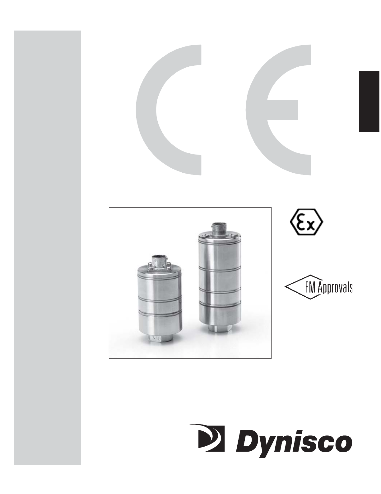
840 Series840 Series
840 Series840 Series
840 Series
StrStr
StrStr
Str
ain Gain G
ain Gain G
ain G
agag
agag
ag
e Pre Pr
e Pre Pr
e Pr
ee
ee
e
ss
ss
s
ss
ss
s
urur
urur
ur
e e
e e
e
TT
TT
T
rr
rr
r
anan
anan
an
smittsmitt
smittsmitt
smitt
erer
erer
er
ss
ss
s
Intrinsically safe and explosion proofIntrinsically safe and explosion proof
Intrinsically safe and explosion proofIntrinsically safe and explosion proof
Intrinsically safe and explosion proof
pressure transmitters with integratedpressure transmitters with integrated
pressure transmitters with integratedpressure transmitters with integrated
pressure transmitters with integrated
amplifier for use in hazardous environmentsamplifier for use in hazardous environments
amplifier for use in hazardous environmentsamplifier for use in hazardous environments
amplifier for use in hazardous environments
P/N 974123
07/05 Rev. C
ECO # 30337
II 1G II 1G
II 1G II 1G
II 1G
AA
AA
A
TEXTEX
TEXTEX
TEX
100a 100a
100a 100a
100a
Page 2
OPERATING MANUAL
TT
TT
T
ABLEABLE
ABLEABLE
ABLE
OFOF
OFOF
OF
C C
C C
C
ONTENTSONTENTS
ONTENTSONTENTS
ONTENTS
ContentContent
ContentContent
Content
PP
PP
P
agag
agag
ag
ee
ee
e
IconIcon
IconIcon
Icon
1. General 3
2. Notes on safety 5
3. Technical data 6
4. Function 15
5. Transport/delivery 16
6. Assembly 17
7. Commissioning 20
8. Maintenance 24
9. Troubleshooting 26
10. CE-Declaration of conformity 27
11. Ex-Declaration of conformity 28
Page 3

3
GENERAL
1.1.
1.1.
1.
GG
GG
G
ENERALENERAL
ENERALENERAL
ENERAL
1.1 Important information .......................................................................................................... 3
1.2 Copyright ............................................................................................................................. 3
1.3 Explanation of icons ............................................................................................................ 4
1.4 Abbreviations ...................................................................................................................... 4
1.5 Correct use .......................................................................................................................... 4
1.6 User’s obligations ................................................................................................................ 4
1.11.1
1.11.1
1.1
II
II
I
MPORMPOR
MPORMPOR
MPOR
TT
TT
T
ANTANT
ANTANT
ANT
INFORMAINFORMA
INFORMAINFORMA
INFORMA
TIONTION
TIONTION
TION
This manual applies to the 840 series only. It must be kept near the equipment in a readily and
immediately accessible location at all times. The content of this manual must be read, understood and
followed in its entirety. This applies in particular to the notes on safety. Following the safety instructions
will help to prevent accidents, defects and malfunctions.
DD
DD
D
YNISCYNISC
YNISCYNISC
YNISC
OO
OO
O will not be held liable for any injury, loss or damage resulting from failure to follow the
instructions in this manual.
If the product malfunctions, in sptie of having followed the operating instructions, please contact the
DD
DD
D
YNISCYNISC
YNISCYNISC
YNISC
OO
OO
O customer service department (see the back of the manual for contact information).
1.21.2
1.21.2
1.2
CC
CC
C
OPYRIGHTOPYRIGHT
OPYRIGHTOPYRIGHT
OPYRIGHT
Copyright law requires that this manual be used for in-house purposes only.
It is strictly forbidden to allow reproduction of any kind “in whole or in part” to persons outside of
Dynisco.
Page 4
4
GENERAL
1.1.
1.1.
1.
33
33
3
EE
EE
E
XPLANAXPLANA
XPLANAXPLANA
XPLANA
TIONTION
TIONTION
TION
OFOF
OFOF
OF
ICIC
ICIC
IC
ONSONS
ONSONS
ONS
The manual uses icons to indicate information pertaining to safety:
Risk of destruction or damage to equipment, machines or installations
General danger to life or limb
Specific danger to life or limb
You MUST do this
The safety instructions are provided again in the individual chapters of the manual.
1.41.4
1.41.4
1.4
AA
AA
A
BBREVIABBREVIA
BBREVIABBREVIA
BBREVIA
TIONSTIONS
TIONSTIONS
TIONS
The following abbreviations are used:
OMOM
OMOM
O M Operating manual
f.s.f.s.
f.s.f.s.
f.s. Of full scale
PTPT
PTPT
PT Pressure transmitter
1.1.
1.1.
1.
55
55
5
CC
CC
C
ORRECTORRECT
ORRECTORRECT
ORRECT
USEUSE
USEUSE
USE
The 840 series of pressure transmitters is specially designed for measuring pressure in explosive
atmospheres (safety class, EEx ia IIC T4, Ta=-20°C to +80°C) as part of a larger overall system. It
contains an integrated signal amplifier. The 840 series of pressure transmitters can be used in media
temperatures up to 85°C. If the pressure transmitter is used in other applications, the safety and
accident prevention regulations specific to that application must be followed.
When using the PT as a safety component in accordance with the EC Machine Directive,When using the PT as a safety component in accordance with the EC Machine Directive,
When using the PT as a safety component in accordance with the EC Machine Directive,When using the PT as a safety component in accordance with the EC Machine Directive,
When using the PT as a safety component in accordance with the EC Machine Directive,
Annex IIc, the equipment manufacturer must take any necessary precautions to ensure thatAnnex IIc, the equipment manufacturer must take any necessary precautions to ensure that
Annex IIc, the equipment manufacturer must take any necessary precautions to ensure thatAnnex IIc, the equipment manufacturer must take any necessary precautions to ensure that
Annex IIc, the equipment manufacturer must take any necessary precautions to ensure that
mm
mm
m
alfalf
alfalf
alf
uu
uu
u
nctionnction
nctionnction
nction
ss
ss
s
of of
of of
of
the P the P
the P the P
the P
TT
TT
T
cc
cc
c
annotannot
annotannot
annot
c c
c c
c
auau
auau
au
se dse d
se dse d
se d
amam
amam
am
agag
agag
ag
e or injure or injur
e or injure or injur
e or injur
yy
yy
y
..
..
.
The 840 series of pressure transmitters are also designed for explosion proof areas approved by
factory mutual for Class I, Division 1, Groups A, B, C & D. Explosion proof models are also
approved for intrinsic safety by factory mutual for Class I, Division 1, Groups A, B, C, & D.
1.61.6
1.61.6
1.6
UU
UU
U
SS
SS
S
ERER
ERER
ER
’’
’’
’
SS
SS
S
OBLIGAOBLIGA
OBLIGAOBLIGA
OBLIGA
TIONSTIONS
TIONSTIONS
TIONS
The operator or owner of the larger overall system, e.g. a machine, is responsible for following the
safety and accident prevention regulations that apply to the specific application.
Page 5
5
SAFETY
2.2.
2.2.
2.
NN
NN
N
OO
OO
O
TETE
TETE
TE
SS
SS
S
ONON
ONON
ON
SS
SS
S
AFETAFET
AFETAFET
AFET
YY
YY
Y
The operator or owner of the larger overall system is responsible for following the safety
and accident prevention regulations that apply to the specific application.
When planning machinery and using the PT, follow the safety and accident prevention
regulations that apply to your application, e.g.:
• EN 60204, Electrical equipment in machines.
• EN 292, Machine safety, general design guidelines.
• DIN 57 100 Part 410, Protection against electric shock.
• EN 50 014:1997, General Requirements
• EN 50 020:1994, Intrinsically safe apparatus
• EN50284:1999, Special requirements fro Group II Category 1G
Mounting and electrical connection of the PT must be done by specialists with EMC training,
following all applicable regulations, and in
pressureless, voltage-free, intrinsically safepressureless, voltage-free, intrinsically safe
pressureless, voltage-free, intrinsically safepressureless, voltage-free, intrinsically safe
pressureless, voltage-free, intrinsically safe
condition with the
machine switched offmachine switched off
machine switched offmachine switched off
machine switched off.
The mThe m
The mThe m
The m
acac
acac
ac
hine muhine mu
hine muhine mu
hine mu
ss
ss
s
tt
tt
t
be sec be sec
be sec be sec
be sec
urur
urur
ur
ed aged ag
ed aged ag
ed ag
ainain
ainain
ain
ss
ss
s
tt
tt
t
bein bein
bein bein
bein
g swg sw
g swg sw
g sw
itit
itit
it
cc
cc
c
hed bhed b
hed bhed b
hed b
acac
acac
ac
kk
kk
k
on! on!
on! on!
on!
Ambient temperature for the electronics housing
mm
mm
m
ax. +80°Cax. +80°C
ax. +80°Cax. +80°C
ax. +80°C (safety class T4 max.).
Higher temperatures can result in damage and malfunction. Do not install the pressure
transmitter in places where this temperature is exceeded.
ExpExp
ExpExp
Exp
lolo
lolo
lo
ss
ss
s
ion hion h
ion hion h
ion h
azaz
azaz
az
arar
arar
ar
d!d!
d!d!
d!
Deviation of the supply voltage from the value given in the technical specifications, or
false polarity, can damage the pressure transmitter and cause malfunctions that can
pose a risk of explosion.
Operate only with an intrinsically safe, EMC compliant power supply with the
following specifications when employing the pressure 4-20mA output:
Supply voltage max.40 V DC
Current output max. 100 mA
Inductivity max. 0
Capacity max. 0.017 µF
For PT’s that are explosion proof Class I, Division 1, Groups A, B, C & D, the power
supply rating is 16-40 Vdc.
Do not lay connecting cables in the direct vicinity of cables carrying higher voltage or
used to switch inductive or capacitive loads.
Page 6
6
TECHNICAL DATA
3.3.
3.3.
3.
TT
TT
T
EE
EE
E
CHNICALCHNICAL
CHNICALCHNICAL
CHNICAL
D D
D D
D
AA
AA
A
TT
TT
T
AA
AA
A
3.1 Ordering guides ................................................................................................................... 6
3.1.1 Ordering guide for x84xx .................................................................................................... 6
3.2 Ordering example ............................................................................................................... 7
3.3 Safety related specifications ................................................................................................7
3.4 Performance characteristics ................................................................................................. 7
3.4.1 Accuracy ............................................................................................................................. 7
3.4.2 Resolution ............................................................................................................................ 8
3.4.3 Repeatabilty ........................................................................................................................ 8
3.5 Pressure side connection ...................................................................................................... 8
3.6 Electrical Termination.......................................................................................................... 8
3.7 Wiring ................................................................................................................................. 9
3.8 Pressure ranges .................................................................................................................. 10
3.8.1 Max. Overload .................................................................................................................. 10
3.8.2 Burst pressure ..................................................................................................................... 10
3.8.3 Natural frequency .............................................................................................................. 10
3.9 Electrical Data .................................................................................................................. 10
3.10 Temperature influence ....................................................................................................... 1 1
3.11 EMC requirements ............................................................................................................. 1 1
3.12 Materials ........................................................................................................................... 1 1
3.13 Environmental Protection .................................................................................................. 1 2
3.14 Weight............................................................................................................................... 12
3.15 Dimensions ........................................................................................................................ 12
3.13.1
3.13.1
3.1
OO
OO
O
RDERINGRDERING
RDERINGRDERING
RDERING
GUIDESGUIDES
GUIDESGUIDES
GUIDES
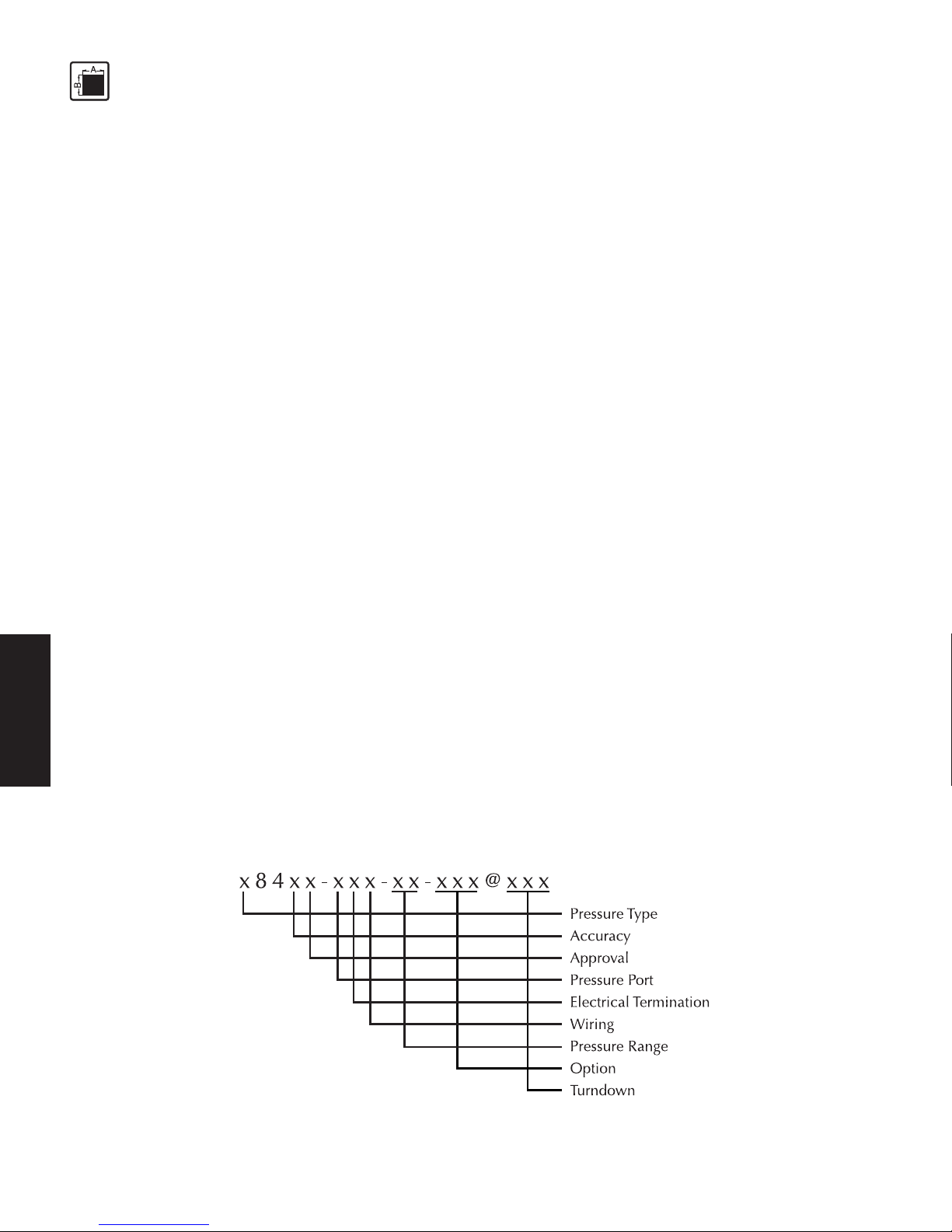
The exact meanings of the letter/digit combinations are given in the corresponding sections of
chapter 3.
3.1.13.1.1
3.1.13.1.1
3.1.1
OO
OO
O
RDERINGRDERING
RDERINGRDERING
RDERING
GUIDEGUIDE
GUIDEGUIDE
GUIDE
FORFOR
FORFOR
FOR
XX
XX
X
8484
8484
84
XXXX
XXXX
XX
Page 7
7
TECHNICAL DATA
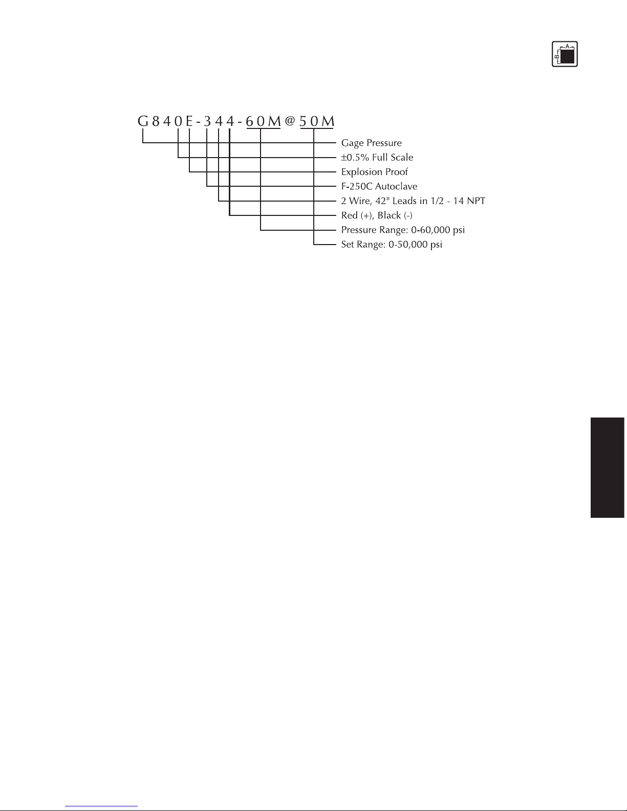
3.23.2
3.23.2
3.2
OO
OO
O
RDERINGRDERING
RDERINGRDERING
RDERING
E E
E E
E
XAMPLEXAMPLE
XAMPLEXAMPLE
XAMPLE
3.33.3
3.33.3
3.3
SS
SS
S
AFETAFET
AFETAFET
AFET
YY
YY
Y
RELARELA
RELARELA
RELA
TEDTED
TEDTED
TED
SS
SS
S
PEPE
PEPE
PE
CIFICACIFICA
CIFICACIFICA
CIFICA
TIONSTIONS
TIONSTIONS
TIONS
ATEX certificate No.: SIRA 03ATEX2422
EX-Safety class EEx ia IIC T4 (Ta = -20°C to +80°C)
FM approvals Class I, Division 1 Groups A, B, C & D
CC
CC
C
erer
erer
er
tified mtified m
tified mtified m
tified m
axax
axax
ax
imum imum
imum imum
imum
vv
vv
v
aluealue
aluealue
alue
ss
ss
s
f f
f f
f
or EExor EEx
or EExor EEx
or EEx
i i
i i
i
a IICa IIC
a IICa IIC
a IIC
T4T4
T4T4
T4
Associated electrical equipment must satisfy the following conditions:
Supply voltage max. 40 V DC
Current output max. 100 mA
Inductivity max. 0
Capacity max. 0.017 µF
3.43.4
3.43.4
3.4
PP
PP
P
ERFORMANCERFORMANC
ERFORMANCERFORMANC
ERFORMANC
EE
EE
E
CHARACHARA
CHARACHARA
CHARA
CTERISCTERIS
CTERISCTERIS
CTERIS
TICTIC
TICTIC
TIC
SS
SS
S
x84xx - xxx - xx - xxx@xxx
3.4.13.4.1
3.4.13.4.1
3.4.1
AA
AA
A
CC
CC
C
CC
CC
C
URAURA
URAURA
URA
CYCY
CYCY
CY
(Linearity, hysterisis and repeatability)
3.4.13.4.1
3.4.13.4.1
3.4.1
AA
AA
A
XX
XX
X
840840
840840
840
±0.50% of full scale
3.4.13.4.1
3.4.13.4.1
3.4.1
BB
BB
B
XX
XX
X
841841
841841
841
±0.25% of full scale
Page 8

8
TECHNICAL DATA
3.4.13.4.1
3.4.13.4.1
3.4.1
CC
CC
C
XX
XX
X
842842
842842
842
±0.15% of full scale
3.4.23.4.2
3.4.23.4.2
3.4.2
RR
RR
R
ESOLUTIONESOLUTION
ESOLUTIONESOLUTION
ESOLUTION
Infinite
3.4.33.4.3
3.4.33.4.3
3.4.3
RR
RR
R
EPEAEPEA
EPEAEPEA
EPEA
TT
TT
T
ABILITABILIT
ABILITABILIT
ABILIT
YY
YY
Y
±0.10% of full scale
3.53.5
3.53.5
3.5
PP
PP
P
RESSURERESSURE
RESSURERESSURE
RESSURE
SIDESIDE
SIDESIDE
SIDE
CONNECTIONCONNECTION
CONNECTIONCONNECTION
CONNECTION
The pressure port thread of the standard 840 Series (Code 0 in the model number) is internal 1/8 - 27
NPT fabricated from high strength stainless steel.
Options available include the following:
Code in Model No.Code in Model No.
Code in Model No.Code in Model No.
Code in Model No.
DescriptionDescription
DescriptionDescription
Description
0 ................................... 1/8 - 27 NPTF, internal
1 ................................... 1/4 - 18 NPT, internal
2 ................................... 7/16 - 20 UNF, internal, O-ring, per MS33649-4
3 ................................... High Pressure, internal fitting per autoclave F-250-C
4 ................................... 1/4 - 18 NPT, external
5 ................................... 1/2 - 14 NPT, external
6 ................................... 7/16 - 20 UNF, external, per MS33656-4
7 ................................... R 1/4 - metric, external
8 ................................... 3/4 - 16 UNF, external, flush diaphragm**
9 ................................... Special (consult factory)
A ................................... 1/2 - 14 BSP, external
B ................................... 7/16 - 14 NPSM, external
C ................................... Autoclave F-562-C
D .................................. 1” BSP, internal
G .................................. Autoclave F-375C
** Each flush diaphragm transducer or transmitter is shipped with a DYNASEAL, Dynisco P/N
633014, for the pressure port seal. Recommended torque, for an adequate seal, is 100 in-lbs. Care
should be exercised with the low pressure ranges. The flush diaphragm can be inadvertently
overloaded with thumb pressure, which can be the equivalent of several hundred psi.
3.63.6
3.63.6
3.6
EE
EE
E
LELE
LELE
LE
CTRICALCTRICAL
CTRICALCTRICAL
CTRICAL
TT
TT
T
ERMINAERMINA
ERMINAERMINA
ERMINA
TIONTION
TIONTION
TION
The electrical terminations of the standard 840 series (Code 4 in the Model Number) is 2 wire, 4”
Page 9
9
TECHNICAL DATA
long leads and a 1/2 - 14 NPT conduit fitting fabricated from high strength stainless steel.
Options available include the following:
Code in Model No.Code in Model No.
Code in Model No.Code in Model No.
Code in Model No.
DescriptionDescription
DescriptionDescription
Description
0 ................................... PT02A-10-6P
1 ................................... PT02H-10-6P, hermetically sealed
2 ................................... PT1H-10-6P, hermetically sealed
3 ................................... 4’ six conductor wire, 1/2 - 14 conduit fitting
4 ................................... 42” two conductor wire with ground, 1/2 - 14 conduit fitting
5 ................................... 30’ two conductor wire with ground, 1/2 - 14 conduit fitting
9 ................................... Special (consult factory)
3.73.7
3.73.7
3.7
WW
WW
W
IRINGIRING
IRINGIRING
IRING
The wiring of the standard 840 series (Code 4 in the Model Number) is 2 wire red and black.
Options available include the following:
Code in Model No.Code in Model No.
Code in Model No.Code in Model No.
Code in Model No.
DescriptionDescription
DescriptionDescription
Description
0 ................................... Connector (see above)
1 ................................... DHF/DV (BLH) wiring
2 ................................... Six conductor wiring
3 ................................... Six conductor DHF/DV (BLH) wiring
4 ................................... 2 wire red and black
5 ................................... 2 wire A and B
6 ................................... 2 wire white and black
9 ................................... Special (consult factory)
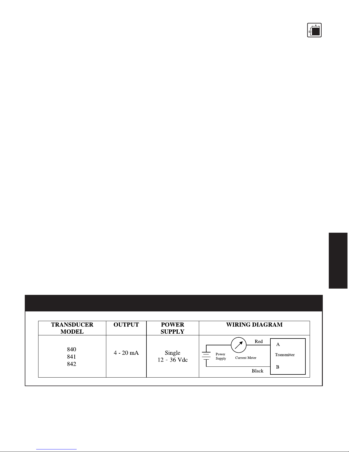
Fig. 3-1Fig. 3-1
Fig. 3-1Fig. 3-1
Fig. 3-1
PP
PP
P
oo
oo
o
ww
ww
w
er er
er er
er
SS
SS
S
upup
upup
up
pp
pp
p
lyly
lyly
ly
R R
R R
R
equirequir
equirequir
equir
ementement
ementement
ement
and and
and and
and
TT
TT
T
ypicypic
ypicypic
ypic
alal
alal
al
WW
WW
W
irinirin
irinirin
irin
g Dig Di
g Dig Di
g Di
agragr
agragr
agr
amam
amam
am
Page 10

10
TECHNICAL DATA
3.83.8
3.83.8
3.8
PP
PP
P
RESSURERESSURE
RESSURERESSURE
RESSURE
RANGESRANGES
RANGESRANGES
RANGES
Model numberModel number
Model numberModel number
Model number
PP
PP
P
ermittermitt
ermittermitt
ermitt
ed pred pr
ed pred pr
ed pr
ee
ee
e
ss
ss
s
ss
ss
s
urur
urur
ur
e re r
e re r
e r
anan
anan
an
gg
gg
g
e in Pe in P
e in Pe in P
e in P
SISI
SISI
SI
x84xx-xxx-2.5C 0-250
x84xx-xxx-5C 0-500
x84xx-xxx-1M 0-750
x84xx-xxx-1.5M 0-1,000
x84xx-xxx-2.5M 0-1,500
x84xx-xxx-3M 0-3,000
x84xx-xxx-5M 0-5,000
x84xx-xxx-7.5M 0-7,500
x84xx-xxx-10M 0-10,000
x84xx-xxx-15M 0-15,000
x84xx-xxx-20M 0-20,000
x84xx-xxx-30M 0-30,000
x84xx-xxx-35M 0-35,000
x84xx-xxx-40M 0-40,000
x84xx-xxx-50M 0-50,000
x84xx-xxx-60M 0-60,000
3.8.13.8.1
3.8.13.8.1
3.8.1
MM
MM
M
AXAX
AXAX
AX
. O. O
. O. O
. O
VERLVERL
VERLVERL
VERL
OO
OO
O
ADAD
ADAD
AD
( (
( (
(
WITHOUTWITHOUT
WITHOUTWITHOUT
WITHOUT
INFLINFL
INFLINFL
INFL
UENCINGUENCING
UENCINGUENCING
UENCING
OPERAOPERA
OPERAOPERA
OPERA
TINGTING
TINGTING
TING
DD
DD
D
AA
AA
A
TT
TT
T
AA
AA
A
))
))
)
x84xx 250-30,000 psi: 1.5x rated pressure
35,000-60,000 psi: 1.2x rated pressure
3.8.23.8.2
3.8.23.8.2
3.8.2
BB
BB
B
URSTURST
URSTURST
URST
PRESSUREPRESSURE
PRESSUREPRESSURE
PRESSURE
250 psi: 10x rated pressure
500-3,000 psi: 5x rated pressure
5,000-10,000 psi: 3x rated pressure
15,000-30,000 psi: 2.5x rated pressure
35,000-60,000 psi: 1.5x rated pressure
3.8.33.8.3
3.8.33.8.3
3.8.3
NN
NN
N
AA
AA
A
TURALTURAL
TURALTURAL
TURAL
FREFRE
FREFRE
FRE
QUENCYQUENCY
QUENCYQUENCY
QUENCY
50 Hz [-3db]
3.93.9
3.93.9
3.9
EE
EE
E
LELE
LELE
LE
CTRICALCTRICAL
CTRICALCTRICAL
CTRICAL
DD
DD
D
AA
AA
A
TT
TT
T
AA
AA
A
Configuration 4-arm Wheatstone bridge strain gauge with int. amplifier
Output signal 2-wire 4 - 20 mA
Supply voltage 16-40 VDC for EEx ia IIC T4 and FM approved explosion proof models
Page 11

11
TECHNICAL DATA
Maximum loop 1200 ohms with 36 VDC
impedance 600 ohms with 24 VDC
0 ohms with 12 VDC
Power consumption ≤20 mA
Zero balance ±2% FSO
Zero adjustment ±5% FSO
3.103.10
3.103.10
3.10
TT
TT
T
EMPERAEMPERA
EMPERAEMPERA
EMPERA
TURETURE
TURETURE
TURE
INFLINFL
INFLINFL
INFL
UENCUENC
UENCUENC
UENC
EE
EE
E
Electronics housingElectronics housing
Electronics housingElectronics housing
Electronics housing
Max. housing temperatures
Safety class T4 -20°C to +80°C
Compenstated -18°C to +66°C
temperature range
Operating -29°C to +85°C
temperature range
Zero shift due to temperature change on electronics housing
x840x ±0.018% full scale/°C typical (±0.036% f.s./°C maximum)
x841x ±0.009% full scale/°C
x842x ±0.006% full scale/°C
3.113.11
3.113.11
3.11
EMC EMC
EMC EMC
EMC
REQUIREMENTSREQUIREMENTS
REQUIREMENTSREQUIREMENTS
REQUIREMENTS
Conforming to CE in accordance with EMC directive.
Electromagnetic Interference DIN EN 550223 1995
Immunity DIN EN 61000-4-2 1995
Radiated, Radio Freq, etc. DIN EN 61000-4-3 1995 +A1:1998+A2:2000
Pulse Magnetic Field DIN EN 61000-4-9 1993 + A1:2001
Surge Immunity DIN EN 61000-4-5 1995 + A1:2000
Conducted Disturbences DIN EN 61000-4-6 1996 + A1:2000
Power Frequency Magnetic Field DIN EN 61000-4-8 1993 + A1:2001
3.123.12
3.123.12
3.12
MM
MM
M
AA
AA
A
TERIALSTERIALS
TERIALSTERIALS
TERIALS
Diaphragm 15-5PH Mat. No. 1.4545
Wetted Materials 17-4PH Mat. No. 517400
Page 12

12
TECHNICAL DATA
3.133.13
3.133.13
3.13
EE
EE
E
NVIRONMENTNVIRONMENT
NVIRONMENTNVIRONMENT
NVIRONMENT
ALAL
ALAL
AL
PROPRO
PROPRO
PRO
TETE
TETE
TE
CTIONCTION
CTIONCTION
CTION
TT
TT
T
OO
OO
O
IE IE
IE IE
IE
CC
CC
C
5 5
5 5
5
22
22
2
99
99
9
PT housing with conduit 1P66 nema 4x
PT02A-10-6P 1P55 nema 4x (Using Dyinsco P/N 711600)
PT02H-10-6P 1P66 nema 4x (Using Dyinsco P/N 711610)
PT1H-10-6P 1P66 nema 4x (Using Dyinsco P/N 711610)
3.143.14
3.143.14
3.14
WW
WW
W
EIGHTEIGHT
EIGHTEIGHT
EIGHT
~17 oz.
3.153.15
3.153.15
3.15
DD
DD
D
IMENSIONSIMENSIONS
IMENSIONSIMENSIONS
IMENSIONS
Page 13

13
TECHNICAL DATA
Fig. 3-2Fig. 3-2
Fig. 3-2Fig. 3-2
Fig. 3-2
x84xx84x
x84xx84x
x84x
Model Model
Model Model
Model
s, Ps, P
s, Ps, P
s, P
arar
arar
ar
tt
tt
t
1 1
1 1
1
Page 14

14
TECHNICAL DATA
Fig. 3-3Fig. 3-3
Fig. 3-3Fig. 3-3
Fig. 3-3
x84xxx84xx
x84xxx84xx
x84xx
Model Model
Model Model
Model
s, Ps, P
s, Ps, P
s, P
arar
arar
ar
tt
tt
t
2 2
2 2
2
Page 15

15
FUNCTION
4.4.
4.4.
4.
FF
FF
F
UNCTIONUNCTION
UNCTIONUNCTION
UNCTION
4.1 Construction ...................................................................................................................... 15
4.2 Description of Functions .................................................................................................... 15
4.14.1
4.14.1
4.1
CC
CC
C
ONSTRUCTIONONSTRUCTION
ONSTRUCTIONONSTRUCTION
ONSTRUCTION
The PTs of series 840’s are industry standard.
The main advantages are:
• Intrinsically safe EEx ia IIC T4
• thermal stability
• resistance to aggressive media
• insensitivity to electromagnetic radiation (EMC)
4.24.2
4.24.2
4.2
DD
DD
D
ESCRIPTIONESCRIPTION
ESCRIPTIONESCRIPTION
ESCRIPTION
OFOF
OFOF
OF
F F
F F
F
UNCTIONSUNCTIONS
UNCTIONSUNCTIONS
UNCTIONS
Through a closed, direct contact measurement system, the PT furnishes an electrical signal that is
proportional to the pressure of the media.
The pressure is applied by the medium on the measuring diaphragm. The deflection of the
measuring diaphragm changes the resistance of the strain gauge bonded to the measuring
diaphragm. The strain gauge is a Wheatstone bridge.
Depending on the model, the integrated amplifier generates an electrical signal (mA) proportional
to the pressure.
Page 16

16
TRANSPORT
5.5.
5.5.
5.
TT
TT
T
RANSRANS
RANSRANS
RANS
PORPOR
PORPOR
POR
TT
TT
T
/ D / D
/ D / D
/ D
ELIVERYELIVERY
ELIVERYELIVERY
ELIVERY
5.1 Transport / packing / transport damage .............................................................................. 16
5.2 Storage .............................................................................................................................. 16
5.3 Scope of delivery .............................................................................................................. 16
ESD sensitive component. Electrostatic discharge may damage the PT. Take ESD
precautions.
5.15.1
5.15.1
5.1
TT
TT
T
RANSRANS
RANSRANS
RANS
PORPOR
PORPOR
POR
TT
TT
T
//
//
/
PP
PP
P
AA
AA
A
CKINGCKING
CKINGCKING
CKING
//
//
/
TRANSTRANS
TRANSTRANS
TRANS
PORPOR
PORPOR
POR
TT
TT
T
DD
DD
D
AMAGEAMAGE
AMAGEAMAGE
AMAGE
• Do not let the PT be damaged by other items during transit.
• Use only the original packaging.
• Report transport damage to
DD
DD
D
YNISCYNISC
YNISCYNISC
YNISC
OO
OO
O immediately in writing.
5.25.2
5.25.2
5.2
SS
SS
S
TT
TT
T
ORAGEORAGE
ORAGEORAGE
ORAGE
• Store the PT in original packaging only.
• Protect against dust and moisture.
5.35.3
5.35.3
5.3
SS
SS
S
CC
CC
C
OPEOPE
OPEOPE
OPE
OFOF
OFOF
OF
DELIVERYDELIVERY
DELIVERYDELIVERY
DELIVERY
• Pressure Transmitter
• Calibration sheet
• Operating manual with declaration of conformity
Page 17

17
ASSEMBLY
6.6.
6.6.
6.
AA
AA
A
SS
SS
S
SS
SS
S
EMBLEMBL
EMBLEMBL
EMBL
YY
YY
Y
6.1 Mounting the Pressure Transmitter ..................................................................................... 1 7
6.2 Electrical connection ........................................................................................................ 18
6.2.1 EMC / CE compliant connection ...................................................................................... 18
6.3 Connection assignments .................................................................................................... 19
Ambient temperature for the electronics housing max. +80°C (safety class T4 max.).
Higher temperatures can result in damage and malfunction.
Do not install the pressure transmitter in places where this temperature is exceeded.
6.16.1
6.16.1
6.1
MM
MM
M
OUNTINGOUNTING
OUNTINGOUNTING
OUNTING
THETHE
THETHE
THE
P P
P P
P
RERE
RERE
RE
SS
SS
S
SURESURE
SURESURE
SURE
TT
TT
T
RANSRANS
RANSRANS
RANS
MITMIT
MITMIT
MIT
TERTER
TERTER
TER
Mounting and electrical connection of the PT must be done by specialists with EMC
training, following all applicable regulations, and in
prpr
prpr
pr
ee
ee
e
ss
ss
s
ss
ss
s
urur
urur
ur
elel
elel
el
ee
ee
e
ss
ss
s
s, s,
s, s,
s,
vv
vv
v
oo
oo
o
ltlt
ltlt
lt
agag
agag
ag
e-fre-fr
e-fre-fr
e-fr
ee,ee,
ee,ee,
ee,
intrinintrin
intrinintrin
intrin
ss
ss
s
icic
icic
ic
alal
alal
al
lyly
lyly
ly
s s
s s
s
afaf
afaf
af
ee
ee
e condition with the
mm
mm
m
acac
acac
ac
hine swhine sw
hine swhine sw
hine sw
itit
itit
it
cc
cc
c
hed offhed off
hed offhed off
hed off.
The machine must be secured against being switched back on!The machine must be secured against being switched back on!
The machine must be secured against being switched back on!The machine must be secured against being switched back on!
The machine must be secured against being switched back on!
ESD sensitive component. Electrostatic discharge may damage the PT. Take ESD
precautions.
Before mounting the PT, check the process connection carefully.
Before mounting the PT, ensure that the process connection is free from media.
To prevent the PT from sticking permanently in the process connection, coat the thread
section of the transmitter with high temperature resistant grease or a suitable parting
agent.
Always use a torque wrench when screwing the PT in and out. Do not apply the tool to
the housing or housing / electrical connection!
• Screw the PT into the process connection and tighten.
Page 18

18
ASSEMBLY
6.26.2
6.26.2
6.2
EE
EE
E
LECTRICALLECTRICAL
LECTRICALLECTRICAL
LECTRICAL
C C
C C
C
ONNECTIONONNECTION
ONNECTIONONNECTION
ONNECTION
Mounting and electrical connection of the PT must be done by specialists with EMC
training, following all applicable regulations, and in
prpr
prpr
pr
ee
ee
e
ss
ss
s
ss
ss
s
urur
urur
ur
elel
elel
el
ee
ee
e
ss
ss
s
s, s,
s, s,
s,
vv
vv
v
oo
oo
o
ltlt
ltlt
lt
agag
agag
ag
e-fre-fr
e-fre-fr
e-fr
ee,ee,
ee,ee,
ee,
intrinintrin
intrinintrin
intrin
ss
ss
s
icic
icic
ic
alal
alal
al
lyly
lyly
ly
s s
s s
s
afaf
afaf
af
ee
ee
e condition with the
mm
mm
m
acac
acac
ac
hine swhine sw
hine swhine sw
hine sw
itit
itit
it
cc
cc
c
hed offhed off
hed offhed off
hed off.
The machine must be secured against being switched back on!The machine must be secured against being switched back on!
The machine must be secured against being switched back on!The machine must be secured against being switched back on!
The machine must be secured against being switched back on!
Do not lay connecting cables in the direct vicinity of cables carrying higher voltage or
used to switch inductive or capacitive loads.
Operate only with an intrinsically safe, EMC compliant power supply with the
following specifications when employing the pressure 4-20 mA output:
Supply voltage max. 40 V DC
Current output max. 100 mA
Inductivity max. 0
Capacity max. 0.017 µF
ESD sensitive component. Electrostatic discharge may damage the PT. Take ESD
precautions.
The electrical connection must comply with EMC requirements.
If the electrical connection is not made as described in section 6.3, or if cables / cable
connectors / cable glands other than those stipulated by
DD
DD
D
YNISCYNISC
YNISCYNISC
YNISC
OO
OO
O are used,
DD
DD
D
YNISCYNISC
YNISCYNISC
YNISC
OO
OO
O
cannot guarantee that EMC requirements will be satisfied.
6.2.16.2.1
6.2.16.2.1
6.2.1
EMC / CE CEMC / CE C
EMC / CE CEMC / CE C
EMC / CE C
OMPLIANTOMPLIANT
OMPLIANTOMPLIANT
OMPLIANT
C C
C C
C
ONNECTIONONNECTION
ONNECTIONONNECTION
ONNECTION
• Earth the machine section with the screw-in trunnion / process connection for the PT in
accordance with regulations. The PT must be connected to earth via the screw-in trunnion /
process connection.
• Connect the shield of the connecting cable on both sides, making sure it conducts with full and
continuous contact.
• When introducing the connecting cable into an EMC compliant switch cabinet, for example,
connect the shield correctely (cable gland, conducting, full contact, continuous) to the
conductive housing or route it via built-in cable connector that is also connected to the
conductive housing.
• Connect unused cable cores or free cable ends correctely to the cable shield on both sides.
Page 19

19
ASSEMBLY
6.36.3
6.36.3
6.3
CC
CC
C
ONNEONNE
ONNEONNE
ONNE
CTIONCTION
CTIONCTION
CTION
A A
A A
A
SS
SS
S
SIGNMENTSIGNMENT
SIGNMENTSIGNMENT
SIGNMENT
SS
SS
S
Conduit / LeadsConduit / Leads
Conduit / LeadsConduit / Leads
Conduit / Leads
Red + Signal/Power
Black - Signal/Power
Green Ground
ConnectorConnector
ConnectorConnector
Connector
A + Signal/Power
B - Signal/Power
Transmitter incorporates over-voltage protection and reverse polarity protection and will not operate
if inputs are reversed.
Page 20

20
COMMISSIONING
7.7.
7.7.
7.
CC
CC
C
OMMISSIONINGOMMISSIONING
OMMISSIONINGOMMISSIONING
OMMISSIONING
7.1 Supply voltage ................................................................................................................... 20
7.2 Calibration ......................................................................................................................... 20
7.3 Zero adjustment ................................................................................................................. 21
7.4 Operation .......................................................................................................................... 21
7.5 Hazardous area electrical configuration ............................................................................ 21
7.17.1
7.17.1
7.1
SS
SS
S
UPPLUPPL
UPPLUPPL
UPPL
YY
YY
Y
VV
VV
V
OLOL
OLOL
OL
TT
TT
T
AGEAGE
AGEAGE
AGE
Please read the entire manual prior to installation and use.
Explosion hazard!Explosion hazard!
Explosion hazard!Explosion hazard!
Explosion hazard!
Deviation of the supply voltage from the value given in the technical specifications, or
false polarity, can damage the pressure transmitter and cause malfunctions that can
pose a risk of explosion.
7.27.2
7.27.2
7.2
CC
CC
C
ALIBRAALIBRA
ALIBRAALIBRA
ALIBRA
TIONTION
TIONTION
TION
Calibrate in pressureless state and at room temperature. Other ambient temperatures
will corrupt the signal. Use an adjustment screwdriver!
The adjustment is made at two potentiometer screws in the cover section of the electronic housing.
• Remove the cap screws from the potentiometers.
Fig. 7-1Fig. 7-1
Fig. 7-1Fig. 7-1
Fig. 7-1
Electronics Housing CoverElectronics Housing Cover
Electronics Housing CoverElectronics Housing Cover
Electronics Housing Cover
• Connect a meter or suitable instrument to the signal output to verify the settings.
• Adjust zero at potentiometer adjusting zero screw and verify on meter.
Page 21

21
COMMISSIONING
7.37.3
7.37.3
7.3
ZZ
ZZ
Z
EROERO
EROERO
ERO
A A
A A
A
DJUSDJUS
DJUSDJUS
DJUS
TMENTTMENT
TMENTTMENT
TMENT
For PTs of series x84x, adjust zero at operating temperature!
• Wait until a steady operating temperature is reached at the pressure sensor.
• Adjust zero at potentiometer adjusting zero screw and verify on the meter.
• Replace the cover screws on the potentiometers.
7.47.4
7.47.4
7.4
OO
OO
O
PERAPERA
PERAPERA
PERA
TIONTION
TIONTION
TION
Before starting the machine, wait until the medium at the diaphragm of the PT has
reached its operating/processing temperature. If the machine is started before the
medium reaches its operating temperature, the PT may be damaged.
Operating temperature at the PT diaphragm
max. 85°C (185°F)max. 85°C (185°F)
max. 85°C (185°F)max. 85°C (185°F)
max. 85°C (185°F). Higher temperatures
will damage the PT.
Ambient temperature for the electronics housing
mm
mm
m
ax. +80°Cax. +80°C
ax. +80°Cax. +80°C
ax. +80°C (safety class T4 max.).
Higher temperatures can result in damage and malfunction.
Do not install the pressure transmitter in places where this temperature is exceeded.
7.57.5
7.57.5
7.5
HH
HH
H
AZARDOUSAZARDOUS
AZARDOUSAZARDOUS
AZARDOUS
A A
A A
A
REAREA
REAREA
REA
E E
E E
E
LELE
LELE
LE
CTRICALCTRICAL
CTRICALCTRICAL
CTRICAL
C C
C C
C
ONFIGURAONFIGURA
ONFIGURAONFIGURA
ONFIGURA
TIONTION
TIONTION
TION
Page 22

22
COMMISSIONING
NON-HAZARDOUS AREA
APARATUS UNSPECIFIED
EXCEPT THAT IT MUST NOT
BE SUPPLIED FROM NOR
CONTAIN U NDER NORMAL
OR ABNORMAL CONDITIONS
A SOURCE OF POTE NTIAL
WITH RESPECT T O EARTH IN
EXCESS OF 250 VOLTS RMS
OR 250 V OLTS DC
CONTROL I NSTRUMENTATION
OPERATING AT OR LESS THAN
250 V RMS 250 VDC
SINGLE
CHANNEL
BARRIER
SINGLE
CHANNEL
BARRIER
INPUT -
CAL +
CAL +
INPUT +
SCS CERT. NO Ex 97D2145
MODELS:
X840S, X841S, X842S
PT290S, PT291S, PT292S
PT241S, PT244S, S242, S243
PRESSURE TRANSMITTER
DYNISCO 4-20 mA 2-WIRE
HAZARDOUS AREA
NON-HAZARDOUS AREA
DUAL CHANNEL
BARRIE R CERTIFICATE N C ( nF ) L (m H) L/R
MTL 2441B
BAS N Ex 9 2C2462 904 33.6 440
P+F ZG30/E x BAS N Ex 84B2198 904 28 3 68
P+F ZG31/E x BAS N Ex 84B2313 904 33.6 440
P+F KHD3-ICR/ Ex 130 BAS N Ex 8 9C2003 904 33.6 440
P+F K HD2-STC3-Ex 1.P BAS N Ex 8 9C2093 904 33.6 440
P+F KHD2-S TC- Ex1 BAS N Ex 89C2093 904 33.6 440
TABLE 1, GROUP IIA
BARRIER CERTIFICATE N C ( nF) L (mH ) L/R
MTL 2441B
BAS N Ex 92C2462 339 12. 6 165
P+F ZG30/E x BAS N Ex 84B2198 339 10.5 138
P+F ZG31/E x BAS N Ex 84B2313 339 12.6 165
P+F KHD3-ICR/E x 130 BAS N Ex 89C2003 3 39 12.6 165
P+F K HD2-STC3-Ex 1.P BAS N Ex 89C 2093 339 12.6 165
P+F KHD2- STC-Ex1 B AS N Ex 89C2093 339 12.6 1 65
TABLE 2, G ROUP IIB
BARRIE R CERTIFICATE N C ( nF ) L (m H) L/R
MTL 2441B
BAS N Ex 9 2C2462 113 4.2 55
P+F ZG30/E x BAS N Ex 84B2198 113 3.5 46
P+F ZG31/E x BAS N Ex 84B2313 113 4.2 55
P+F KHD3-ICR/E x 130 BAS N Ex 8 9C2003 113 4.2 55
P+F K HD2-STC3-Ex 1.P BAS N Ex 89C2 093 113 4.2 55
P+F KHD2-S TC -Ex1 BAS N Ex 89C2093 113 4.2 55
TABLE 3, GR OUP IIC
NOTES:
1. THE ELECTRICAL CIRCUIT IN THE HAZARDOUS AREA MUST BE CAPABL E OF
WITHSTANDING AN AC TEST VOLTAGE OF 5 00 VOLTS R.M.S. TO EARTH OR
FRAME OF THE APPARATUS FOR O NE MINUTE.
2. THE CAPACITANCE AND INDUCTANCE OR INDUCTANCE / RESISTANCE (L/R)
RATIO OF THE HAZARDOUS AREA CABLES MUST NOT EXCEED THE VALUES
SHOWN ON TABLES 1,2 & 3.
5. IF TWO OR MORE SEPARATE CIRCUITS ARE TO BE KEPT SEPARATE
WITHIN A MULTICORE ,THEN TYPE A OR B CABLES MUST BE USED, OR
SEPARATE CABLES TO BE USED.
6. CABLE SCREENS ARE TO BE EARTHED AT ONE END ONLY.
'IS'
4. THE INSTALLATION MUST COMPLY WITH THE NATIONAL INSTALLATION
REQUIREMENTS (E.G. IN THE UK, BS EN 60079-14:1997).
OR
TWO OF THE FOLLOWING SINGLE CHANNEL BARRIERS:
PEPPERL/FUCHS ZG31Ex OR
PEPPERL/FUCHS KHD3-ICR/Ex130 200 Y71688 OR
PEPPERL/FUCHS KHD2-STC3-Ex 1.P OR
PEPPERL/FUCHS KHD2-STC3-Ex 1.
ONE OF T HE FOLLOWING DUAL CHA NNEL BARRIERS:
A) PEPPER & FUCHS ZG30/Ex
B) MTL 2441B
3. NON-HAZARDOUS AREA EQUIPMENT SHALL COMPRISE
7. SYSTEM LABEL TO B E AFFIXED AT THE INTERFACE OF ' ' OR 'NON- '
CIRCUITS OR ADJACENT TOTHE PRINCIPAL APPARATUS.
SIRA SYST. Ex 98E2139.
IS IS
Fig. 7-2Fig. 7-2
Fig. 7-2Fig. 7-2
Fig. 7-2
ElEl
ElEl
El
ectricectric
ectricectric
ectric
alal
alal
al
C C
C C
C
onfiguronfigur
onfiguronfigur
onfigur
ation fation f
ation fation f
ation f
or Intrinor Intrin
or Intrinor Intrin
or Intrin
ss
ss
s
icic
icic
ic
alal
alal
al
lyly
lyly
ly
SafSaf
SafSaf
Saf
e Haze Haz
e Haze Haz
e Haz
arar
arar
ar
doudou
doudou
dou
ss
ss
s
Ar Ar
Ar Ar
Ar
ee
ee
e
aa
aa
a
ss
ss
s
Page 23

23
COMMISSIONING
NOTES:
1. INSTALLATION MUST BE IN ACCORDANCE
WITH THE NATIONAL ELECTRIC CODE
( NFPA 70, ARTICLE 504 ) AND ANSI / ISA RP 12.6.
2. PROTECTIVE ASSOCIATED APPARATUS MUST BE
INSTALLED IN ACCORDANCE WITH
MANUFACTURERS INSTALLATION DRAWING.
4. ANY FMRC APPROVED SINGLE OR DUAL CHANNEL
BARRIER WITH ENTITY PARAMETERS OF Voc OR
V < 40V, sc OR < 100 mA, Ca > .017 uf, La > 0 mH
OR ONE OF THE FOLLOWING PROTECTIVE BARRIERS:
MTL 5042 OR PEPPERL / FUCHS KFD2-STC4-EX1.
II
3. ANY FMRC APPROVED SINGLE OR DUAL CHANNEL
BARRIER WITH ENTITY PARAMETERS OF Voc OR
V < 25 V, sc OR, < 100 mA, Ca > .017 uf, La > 0 mH
OR PROTECTIVE BARRIER PEPPERL / FUCHS Z111/Ex.
II
(CLASS1,DIV1,GROUPSA,B,C,D)
DYNISCO 4-20 mA 2-WIRE
PRESSURE TRANSMITTER
S242, S243
PT290S, PT291S, PT292S
X840S, X841S, X842S
MODELS: PT241S, PT244S,
NOTE 3
NOTE 4
NON-HAZARDOUS AREA
HAZARDOUS AREA
INPUT +
CAL -
CAL +
INPUT -
DUAL
CHANNEL
BARRIER
SINGLE
CHANNEL
BARRIER
CONTROL INSTRUMENTATION
OPERATING AT OR LESS THAN
250 V RMS 250 VDC
NON-HAZARDOUS AREA
APARATUS UNSPECIFIED
EXCEPT THAT IT MUST NOT
BE SUPPLIED FROM NOR
CONTAIN UNDER NORMAL
OR ABNORMAL CONDITIONS
A SOURCE OF POTENTIAL
WITH RESPECT TO EARTH IN
EXCESS OF 250 VOLTS RMS
OR 250 VOLTS DC
†
†
†
†
Fig. 7-3Fig. 7-3
Fig. 7-3Fig. 7-3
Fig. 7-3
ElEl
ElEl
El
ectricectric
ectricectric
ectric
alal
alal
al
C C
C C
C
onfiguronfigur
onfiguronfigur
onfigur
ation fation f
ation fation f
ation f
or Expor Exp
or Expor Exp
or Exp
lolo
lolo
lo
ss
ss
s
ion Prion Pr
ion Prion Pr
ion Pr
oofoof
oofoof
oof
Haz Haz
Haz Haz
Haz
arar
arar
ar
doudou
doudou
dou
ss
ss
s
Ar Ar
Ar Ar
Ar
ee
ee
e
aa
aa
a
ss
ss
s
Page 24

24
MAINTENANCE
8.8.
8.8.
8.
MM
MM
M
AINTENANCEAINTENANCE
AINTENANCEAINTENANCE
AINTENANCE
8.1 Maintenance ..................................................................................................................... 24
8.2 Repair/disposal .................................................................................................................. 24
8.3 Warranty ............................................................................................................................ 25
8.18.1
8.18.1
8.1
MM
MM
M
AINTENANCEAINTENANCE
AINTENANCEAINTENANCE
AINTENANCE
Mounting and electrical connection of the PT must be done by specialists with EMC
training, following all applicable regulations, and in
prpr
prpr
pr
ee
ee
e
ss
ss
s
ss
ss
s
urur
urur
ur
elel
elel
el
ee
ee
e
ss
ss
s
s, s,
s, s,
s,
vv
vv
v
oo
oo
o
ltlt
ltlt
lt
agag
agag
ag
e-fre-fr
e-fre-fr
e-fr
ee,ee,
ee,ee,
ee,
intrinintrin
intrinintrin
intrin
ss
ss
s
icic
icic
ic
alal
alal
al
lyly
lyly
ly
s s
s s
s
afaf
afaf
af
ee
ee
e condition with the
mm
mm
m
acac
acac
ac
hine swhine sw
hine swhine sw
hine sw
itit
itit
it
cc
cc
c
hed offhed off
hed offhed off
hed off.
The mThe m
The mThe m
The m
acac
acac
ac
hine muhine mu
hine muhine mu
hine mu
ss
ss
s
tt
tt
t
be sec be sec
be sec be sec
be sec
urur
urur
ur
ed aged ag
ed aged ag
ed ag
ainain
ainain
ain
ss
ss
s
tt
tt
t
bein bein
bein bein
bein
g swg sw
g swg sw
g sw
itit
itit
it
cc
cc
c
hed bhed b
hed bhed b
hed b
acac
acac
ac
kk
kk
k
on! on!
on! on!
on!
Burn hazard!Burn hazard!
Burn hazard!Burn hazard!
Burn hazard!
The PT can be very hot when removed.
WW
WW
W
ee
ee
e
ar prar pr
ar prar pr
ar pr
otot
otot
ot
ectivectiv
ectivectiv
ectiv
e gloe glo
e gloe glo
e glo
vv
vv
v
ee
ee
e
s!s!
s!s!
s!
ESD sensitive component. Electrostatic discharge may damage the PT. Take ESD
precautions.
Always remove the PT before cleaning the machine with abrasives or steel wire brushes
or suchlike.
Removing the transmitter if the medium is in solidified condition can damage the
diaphragm of the PT.
Do not clean the screw-in section of the PT with hard objects. This will damage the PT!
Always use a torque wrench applied to the designated hexagon collar when screwing
the PT in and out. Do not apply the tool to the housing or housing/electrical
connection!
• Remove the PT.
• Carefully clean the PT/process connection of the transmitter with a soft cloth, while the
medium is still malleable.
8.28.2
8.28.2
8.2
RR
RR
R
EPEP
EPEP
EP
AIRAIR
AIRAIR
AIR
//
//
/
DISDIS
DISDIS
DIS
POPO
POPO
PO
SS
SS
S
ALAL
ALAL
AL
Please send defective PTs to your
DD
DD
D
YNISCYNISC
YNISCYNISC
YNISC
OO
OO
O representative.
For addresses, see the back cover of the operating manual.
Page 25

25
MAINTENANCE
8.38.3
8.38.3
8.3
WW
WW
W
ARRANTYARRANTY
ARRANTYARRANTY
ARRANTY
This DYNISCO product is warranted under terms and conditions set forth in the DYNISCO web
pages. Go to www.dynisco.com and click “warranty” at the bottom of any page for complete
details.
Page 26

26
TROUBLESHOOTING
9.9.
9.9.
9.
TT
TT
T
ROUBLESHOOTINGROUBLESHOOTING
ROUBLESHOOTINGROUBLESHOOTING
ROUBLESHOOTING
FF
FF
F
auau
auau
au
ltlt
ltlt
lt
PP
PP
P
oo
oo
o
ss
ss
s
ss
ss
s
ibib
ibib
ib
ll
ll
l
e Ce C
e Ce C
e C
auau
auau
au
sese
sese
se
ResolutionResolution
ResolutionResolution
Resolution
No signal Cable breakage or poor contact Check cable and contact,
or replace
No supply voltage Check supply voltage
Strong zero shift Process connection incorrectly Check process connection with
when screwing in produced (alignment error) test bolt,rework if necessary
Mounting torque too high Adjust to recommended
mounting torque
No signal change Plug forming in front of diaphragm Check process connection
despite pressure rise
Diaphragm damaged Send pressure transmitter to
DD
DD
D
YNISCYNISC
YNISCYNISC
YNISC
OO
OO
O for repair
Page 27

27
CE-DECLARATION
10.10.
10.10.
10.
CC
CC
C
EE
EE
E
D D
D D
D
EE
EE
E
CLARACLARA
CLARACLARA
CLARA
TIONTION
TIONTION
TION
OFOF
OFOF
OF
C C
C C
C
ONFORMITONFORMIT
ONFORMITONFORMIT
ONFORMIT
YY
YY
Y
Page 28

28
EX-DECLARATION
11.11.
11.11.
11.
EE
EE
E
XX
XX
X
D D
D D
D
EE
EE
E
CLARACLARA
CLARACLARA
CLARA
TIONTION
TIONTION
TION
OFOF
OFOF
OF
C C
C C
C
ONFORMITONFORMIT
ONFORMITONFORMIT
ONFORMIT
YY
YY
Y
Page 29

29
EX-DECLARATION
Page 30

30
EX-DECLARATION
Page 31

Page 32

OPERATING MANUAL
VV
VV
V
ii
ii
i
ss
ss
s
itit
itit
it
u u
u u
u
ss
ss
s
on the w on the w
on the w on the w
on the w
orlorl
orlorl
orl
d wd w
d wd w
d w
ide wide w
ide wide w
ide w
ee
ee
e
b:b:
b:b:
b:
wwwwww
wwwwww
www
..
..
.
dydy
dydy
dy
nini
nini
ni
ss
ss
s
cc
cc
c
oo
oo
o
..
..
.
cc
cc
c
omom
omom
om
DyniscoLLC
38 Forge Parkway
Franklin, MA 02038
USA
Tel: +1 508 541 9400
Fax: +1 508 541 9436
Email: InfoInst@dynisco.com
Dynisco Extrusion
1291 19th St Ln NW
Hickory, NC 28601
Tel: 828-326-9888
Fax: 828-326-8882
Email: InfoExtr@dynisco.com
Dynisco Europe GmbH
Wannenäckerstraße 24
74078 Heilbronn
Deutschland
Tel: +49 7131 2970
Fax:+49 7131 23260
Email: DyniscoEurope@dynisco.com
Dynisco Instruments S.a.r.l.
466, rue du Marché Rollay
94500 Champigny sur Marne
France
Tel: +33 1 4881 8459
Fax: +33 1 4881 8334
Email: DyniscoFrance@dynisco.com
Dynisco.s.r.l.
Via Adriatico, 2/2
20162 Milano
Italia
Tel: +39 02 661 01733
Fax: +39 02 661 02908
Email: DyniscoItaly@dynisco.com
Dynisco UK Ltd.
Unit 2B Crowood House
Gipsy Lane
Swinden NN2 8YY
United Kingdom
Tel: +44 1527 577077
Fax: +44 1527 577070
Email: DyniscoUK@dynisco.com
Dynisco SPOL, S.R.O.
cp. 579
756 55 Dolni Becva
Czech Republic
Tel: +42 0571 647228
Fax: +42 0571 647224
Email: Dynisco_cz@ova.pvtnet.cz
Dynisco B.V.
Weidehek 53A
4824 At Breda
The Netherlands
Tel: +31 (0) 76 549 0530
Fax: +31 (0) 76 549 0540
Email: Dynisco-BV@dynisco.com
 Loading...