

Page 1
Dynisco Polymer Test Systems
LMI 4000
Series
Melt
Indexer
Manual
Version 4.1
Manual Part Number: M0704 www.dynisco.com
Original Language Version
38 Forge Parkway
Franklin, MA 02038
Phone +1 508 541 9400
Fax +1 508 541 6206
Page 2

Notice
This manual contains descriptions, drawings and specifications for a Dynisco Polymer Test
Systems Product. Equipment or products made prior to or subsequent to the publication
date of this manual may have parts, features, options or configurations that are not covered
in this manual. Specifications contained herein are subject to change by Dynisco Polymer
Test Systems without prior notice. Dynisco Polymer Test Systems is not responsible for
errors or omissions that may be contained herein or for incidental or consequential damages
in connection with the furnishing or use of this information. The information contained in
this manual is the property of Dynisco Polymer Test Systems, unless otherwise stated.
Comments or suggestions for possible improvement to the manual are appreciated and may
be sent to the following location:
38 Forge Parkway
Franklin, MA 02038
Phone +1 508 541 9400
Fax +1 508 541 6206
www.dynisco.com
Page 3

Contents
Introduction 1
Getting Started 6
Safety 10
Series 4000 Melt Indexer Operation Manual Contents i
About DYNISCO POLYMER TEST SYSTEMS Inc. ................................................................................... 1
How to Use this Manual.................................................................................................................................. 1
Typographic Conventions ............................................................................................................................... 2
How to Contact Dynisco Polymer Test Systems Inc....................................................................................... 2
Model Descriptions ......................................................................................................................................... 2
On Overview of MI ......................................................................................................................................... 3
ASTM Melt Index Tests.................................................................................................................................. 3
Method A .......................................................................................................................................... 3
Method A/B ...................................................................................................................................... 3
Method B .......................................................................................................................................... 3
Series 4000 Product Offerings: ....................................................................................................................... 3
Introduction....................................................................................................................................... 3
Model 4001 ....................................................................................................................................... 4
Model 4002 ....................................................................................................................................... 4
Model 4003 ....................................................................................................................................... 4
Model 4004 ....................................................................................................................................... 4
Method B Encoder Option ................................................................................................................ 4
Pneumatic Lift................................................................................................................................... 5
Mini-Lift ........................................................................................................................................... 5
Intrinsic Viscosity Option ................................................................................................................. 5
Unpacking the Indexer .................................................................................................................................... 6
Bench Requirements and Placement ................................................................................................. 6
Level the Melt Indexer ...................................................................................................................... 6
Pneumatic lift setup........................................................................................................................... 7
Installing the Digital Encoder ........................................................................................................... 7
RTD Connection ............................................................................................................................... 9
Power Cord ....................................................................................................................................... 9
Printer Connection ............................................................................................................................ 9
Computer Connection ....................................................................................................................... 9
Options:............................................................................................................................................. 9
Use gloves, it's HOT! .................................................................................................................................... 10
Electrical Hazard ........................................................................................................................................... 10
Calibration Thermometers use Mercury........................................................................................................ 10
Pinch Points................................................................................................................................................... 11
Fumes from Materials ................................................................................................................................... 11
Pre-Run Check List ....................................................................................................................................... 11
Page 4

Series 4000: A Guided Tour 12
Four Options from the main menu screen. .................................................................................................... 12
Overview......................................................................................................................................... 12
Setup ............................................................................................................................................... 12
Edit.................................................................................................................................................. 12
Run.................................................................................................................................................. 12
System............................................................................................................................................. 12
Navigating the Keypad.................................................................................................................................. 13
Introduction..................................................................................................................................... 13
The Keypad ..................................................................................................................................... 13
Keypad Definitions ......................................................................................................................... 14
Configuring the Instrument 15
Series 4000 Melt Indexer Operation Manual Contents ii
Intro: The SYS (SYSTEM) Mode................................................................................................................. 15
Selecting CALIB (Calibration) in the SYS Mode ......................................................................................... 16
CALIB:Digital Flag Home.............................................................................................................. 16
CALIB:RTD Electronics................................................................................................................. 16
CALIB:RTD Sensor........................................................................................................................ 16
CALIB:Optical Flag........................................................................................................................ 16
CALIB:Intrinsic Viscosity Offset ................................................................................................... 16
Selecting TEST in the SYS Mode ................................................................................................................. 17
TEST:RTD Display ........................................................................................................................ 17
TEST:Digital Encoder .................................................................................................................... 17
TEST:Printer ................................................................................................................................... 17
TEST:Display Brightness ............................................................................................................... 17
The SETUP mode ......................................................................................................................................... 17
Introduction..................................................................................................................................... 17
REJECTION ................................................................................................................................... 17
AVERAGE ..................................................................................................................................... 17
MFR / MVR .................................................................................................................................... 17
B FLAG .......................................................................................................................................... 17
VISCOSITY.................................................................................................................................... 17
PRINTER ........................................................................................................................................ 17
FORM FEED .................................................................................................................................. 17
COMM PORT................................................................................................................................. 18
MINI LIFT ...................................................................................................................................... 18
PNEU LIFT..................................................................................................................................... 18
LOCKOUT ..................................................................................................................................... 18
DATE and TIME ............................................................................................................................ 18
MACHINE ID................................................................................................................................. 18
LANGUAGE .................................................................................................................................. 18
ORIFICE DIA ................................................................................................................................. 18
ORIFICE LEN ................................................................................................................................ 18
Programming ................................................................................................................................................. 18
Introduction..................................................................................................................................... 18
Create (New) ................................................................................................................................... 18
Recall (Old)..................................................................................................................................... 18
Save Program .................................................................................................................................. 18
While EDITING ............................................................................................................................. 18
Method A Run Parameters .............................................................................................................. 19
Method A/B Run Parameters .......................................................................................................... 19
Method B Run Parameters .............................................................................................................. 19
RATIO (Flow Ratio) Run parameters .............................................................................................. 20
Page 5

Run a Program............................................................................................................................................... 20
Method "A" Run 21
Programming a Method A ............................................................................................................................. 21
Loading the Sample....................................................................................................................................... 23
User Tips: ...................................................................................................................................................... 25
General Description ........................................................................................................................ 21
Calculations: Method A .................................................................................................................. 21
Power-Up ........................................................................................................................................ 21
Introduction..................................................................................................................................... 21
Machine Setup ................................................................................................................................ 22
Loading the Barrel .......................................................................................................................... 23
Bubbles ........................................................................................................................................... 23
RUN ................................................................................................................................................ 23
Making the Cut ............................................................................................................................... 24
Weigh the Sample ........................................................................................................................... 24
Cleaning Up .................................................................................................................................... 25
User Tip #1 ..................................................................................................................................... 25
User Tip #2 ..................................................................................................................................... 25
Always leave the barrel clean. ........................................................................................................ 26
Cleaning Up a really Big Mess ....................................................................................................... 26
Method "A/B" Run 27
Programming Method A/B ............................................................................................................................ 27
The Actual Run ............................................................................................................................................. 29
General Description ........................................................................................................................ 27
Calculations : Method A/B ............................................................................................................. 27
Introduction..................................................................................................................................... 28
Machine Setup ................................................................................................................................ 28
How to do it: Step by Step .............................................................................................................. 29
Instrument Prep ............................................................................................................................... 29
Loading the Barrel .......................................................................................................................... 29
Inserting the Timing Flag................................................................................................................ 30
Making the Cut ............................................................................................................................... 31
Cleaning Up .................................................................................................................................... 31
Your data......................................................................................................................................... 31
Method "B" Run 32
Programming Method B ................................................................................................................................ 33
The Actual Run ............................................................................................................................................. 35
General Description ........................................................................................................................ 32
Calculations: Method B .................................................................................................................. 32
Method B Flags Setup..................................................................................................................... 33
Choosing a Timing Flag.................................................................................................................. 34
How to do it: Step by Step .............................................................................................................. 35
Instrument Prep ............................................................................................................................... 35
Loading the Barrel .......................................................................................................................... 35
Timing Flag and Starting the Run ................................................................................................... 36
Cleaning Up .................................................................................................................................... 37
“Flow Ratio” Runs 39
Series 4000 Melt Indexer Operation Manual Contents iii
Flow Rate Ratio test and the Pneumatic Lift Option..................................................................................... 39
Page 6

What is it? ....................................................................................................................................... 39
Why do it?....................................................................................................................................... 39
Flow Rate Ratio - How to Do It ...................................................................................................... 39
“Intrinsic Viscosity” Runs with PET 41
Calculating PET I.V. from the Melt Indexer ................................................................................................. 41
What is it? ....................................................................................................................................... 41
Why do it?....................................................................................................................................... 42
How to do it .................................................................................................................................... 42
Charge Weight 44
The Amount of Sample ................................................................................................................................. 44
A-Standard Operating Procedure 46
Introduction:.................................................................................................................................... 46
Instrument Preparation .................................................................................................................... 46
Conducting the Test ........................................................................................................................ 47
Clean Up ......................................................................................................................................... 47
Your data......................................................................................................................................... 47
Out of Control Action List 48
Actions ............................................................................................................................................ 48
Generic Run Check List .................................................................................................................. 48
Model 4004 and Computer Control 49
Introduction ................................................................................................................................................... 49
The Digital Encoder: Use and Calibration 50
Programming for use with the Digital Encoder............................................................................................. 52
Encoder Homing and Maintenance ............................................................................................................... 53
Introduction..................................................................................................................................... 50
Method B Encoder Option .............................................................................................................. 50
Encoder Advantages ....................................................................................................................... 50
Why use it? ..................................................................................................................................... 51
Digital Encoder Installation ............................................................................................................ 51
Method B: Setup ............................................................................................................................. 52
Enable the Digital Encoder ............................................................................................................. 52
Auto Flag ON/OFF ......................................................................................................................... 52
Flag Calculation MANUAL or AUTO? ......................................................................................... 53
AUTO flag selected ........................................................................................................................ 53
So you picked MANUAL ............................................................................................................... 53
Digital Flag Home........................................................................................................................... 53
Testing and Maintenance ................................................................................................................ 53
Complete Digital Encoder Calibration ............................................................................................ 54
Referenced Spec D1238-95 ............................................................................................................ 54
Pneumatic Lift Options 59
Series 4000 Melt Indexer Operation Manual Contents iv
Pneumatic Lift ............................................................................................................................................... 59
Introduction..................................................................................................................................... 59
Activation and Operation ................................................................................................................ 59
Page 7

Mini-Lift........................................................................................................................................................ 59
Introduction..................................................................................................................................... 59
Activation and Operation ................................................................................................................ 59
Instrument Calibration 60
RTD Electronics ............................................................................................................................................ 60
RTD Sensor ................................................................................................................................................... 60
Calibration Steps: ............................................................................................................................ 60
SINGLE .......................................................................................................................................... 60
DOUBLE ........................................................................................................................................ 61
Optical Flag ................................................................................................................................................... 61
Calibration Steps: ............................................................................................................................ 61
Digital Encoder Calibration .......................................................................................................................... 62
Calibration:Digital Flag Home........................................................................................................ 62
Intrinsic Viscosity ......................................................................................................................................... 62
Offset .............................................................................................................................................. 62
Instrument Maintenance and Troubleshooting 63
Maintenance .................................................................................................................................................. 63
Daily................................................................................................................................................ 63
Weekly ............................................................................................................................................ 63
Monthly or Long Term ................................................................................................................... 63
Barrel Diameter............................................................................................................................... 64
Support Vendors ............................................................................................................................. 64
Conversion Factors ......................................................................................................................... 65
Troubleshooting ............................................................................................................................................ 65
Flow Rates are Changing ................................................................................................................ 65
Temperature is Unstable ................................................................................................................. 66
Mercury Separation in Thermometer .............................................................................................. 66
Reuniting Mercury Thermometers .................................................................................................. 66
Pneumatic Lift Troubleshooting ..................................................................................................... 67
Pneumatic Lift maintenance............................................................................................................ 67
Questions and Answers 69
Typical Problems ............................................................................................................................ 69
Typical Questions ........................................................................................................................... 70
Glossary of Terms 73
Series 4000 Melt Indexer Operation Manual Contents v
Digital Flag, Digital Encoder........................................................................ 73
Firmware....................................................................................................... 73
Flow rate ....................................................................................................... 73
Flow Rate Ratio ............................................................................................ 73
Intrinsic Viscosity ......................................................................................... 73
Melt Flow Indexer ........................................................................................ 73
Method A ...................................................................................................... 73
Method A/B .................................................................................................. 73
Method B ...................................................................................................... 73
MVI .............................................................................................................. 73
Optical Flag or Optical Eye Sensor .............................................................. 73
Pneumatic Lift .............................................................................................. 73
RTD .............................................................................................................. 73
Timing Flag .................................................................................................. 73
Page 8

Setting-Up USB Communications 74
Set-Up with Daisy Software ........................................................................ 74
Set-Up with MI Works Software.................................................................. 77
Index 81
Series 4000 Melt Indexer Operation Manual Contents vi
Page 9

Introduction
About Dynisco Polymer Test
Dynisco Polymer Test is a manufacturer of laboratory test equipment supplying
capillary rheometers, melt indexers, a variety of impact testers, coefficient of
friction testers, contact angle testers, film tensile testers and other small test
devices. Through its innovative work with electronics and mechanical design,
Dynisco Polymer Test Systems has carved a niche in the market place by
providing the highest performance per cost ratio in the business.
The company was founded in the late '60's in Honey Brook P.A., and is built on
two principles: quality workmanship and outstanding service. Dynisco Polymer
Test Systems' mission has grown to meeting the physical testing needs of the
plastics, food, and rubber industries by providing high quality equipment and
services at low cost. The company was purchased in 1988 by Dynisco, and is
now a wholly owned subsidiary of Dynisco Inc. Dynisco, an ISO 9002 qualified
supplier, is the world’s largest manufacturer of pressure transducers and is
located in Franklin, MA.
How to Use this Manual
This manual describes the setup procedure and basic operation of the Dynisco
Polymer Test Systems Series 4000 class indexers. With the accompanying
MIWORKS or Daisy software manual (if software was purchased) it provides
the complete description of resources at your command. It is not necessary to
read this manual in its entirety. However, even experienced rheologists and
technicians can benefit from the SAFETY tips and cleaning suggestions learned
over many years of operating these instruments in our applications laboratory.
The Getting Started Chapter explains the details of setting up the instrument and
preparing it for use. Please take a few minutes to review the safety precautions
that should be taken when operating Dynisco Polymer Test Systems Melt Index
Series 4000 Melt Indexer Operation Manual Introduction 1
equipment.
Page 10

Typographic Conventions
Italics: Rheological items that have defining equations presented in the manual
are shown in italics. If you come across an italicized item that is unclear you
can be sure it has a mathematical definition previously defined in the manual.
Bold Italics: These are parameters that are set from the front panel on the
indexer (i.e. Melt Time, Mtd A Time etc.). These parameters are entered into
the indexer's control programs via the indexer key pad.
BOLD ALL CAPITALS: This indicates an actual key found on the indexer
key pad. Example: Press the RESET button to return to main screen. Underlined
Items: Underlined items' head paragraphs or sections that pertain to the
particular item or model underlined. If you do not have or are not interested in
the underlined item skip the section that follows it. Underlining is also used
to emphasize safety issues.
How to Contact Dynisco Polymer
Test Inc.
Before calling Dynisco Polymer Test be sure you have gone through the
"Answers to common questions" section of the manual. To help us handle your
questions as quickly as possible, have the following items ready before you call:
Machine name and model number
Machine serial number (on back panel)
Current version of firmware (Power up unit to see)
Computer system make and model
Current version of software (if applicable)
Call Dynisco Polymer Test directly at (508) 541-9400 and ask for technical
support. Should you wish to comment or query in writing, address to:
Dynisco Polymer Test Inc. : Customer Service
38 Forge Parkway
Franklin, MA 02038
You can also reach us through the internet at: www.Dynisco.com.
Model Descriptions
The DYNISCO POLYMER TEST SYSTEMS Series 4000 Melt Flow Indexer
incorporates the latest in micro-electronic technology. It is designed to make
melt flow rate testing faster, more accurate and flexible, and generate more
rheological information. The heart of the system is a 32 bit microprocessor
developed by DYNISCO POLYMER TEST SYSTEMS. It controls
temperature, responds to keyboard commands and implements testing programs.
Series 4000 Melt Indexer Operation Manual Introduction 2
System capabilities:
Communications with computers
Direct output to printer
Stores test conditions in program memory
Shows instantaneous flow rate read-out
Battery backed-up date & test conditions
Page 11

Download to MS-DOS compatible systems
Methods A, B, or A/B conversion and flow rate ratio
Automated purge or weight lowering
Control temperature within 0.1C.
Automatic check of RTD sensor probe and over temperature alarm.
On Overview of MI
A flow rate test is a measure of a polymer's mass flow rate (grams extruded in
10 minutes) using a particular orifice under specified conditions of temperature
and load. Machines that determine flow rate are generally called Melt Indexers.
Test methods by ISO, DIN, ASTM and others specify heat chamber and piston
tip diameter such that the shear stress on the polymer is the same in all machines
for a given load. In addition, material specification guidelines (by ISO, DIN,
ASTM, GM etc) may exist which give further constraints on how a particular
type of material may be run.
The tests we are interested in performing are those described by ASTM D1238
and ISO 1133. This manual in no way supersedes either of these documents.
The precision and accuracy of the test has been determined by ASTM method
D1238 and can be found at the end of this manual. Contributing to both
precision and accuracy are operator variances such as; packing technique,
cleaning, cutting, weighing etc. With moisture sensitive polymers, dryness can
also play a major role, and time can be a factor with thermally unstable
polymers, so procedures must be identical. Dynisco Polymer Test Systems has
found that charging a consistent mass of material into the barrel (0.1 grams) is
the most critical factor in getting precise data.
ASTM Melt Index Tests
Two basic methods have been developed for running flow rate tests under D1238, Methods A and B. Method A is simply the collection of extrudate over
time, while Method B is the measurement of time for the flow of a fixed volume
Method A
Method A/B
Method B
Series 4000 Melt Indexer Operation Manual Introduction 3
Introduction
of polymer.
Method A -- the test is completely manual and is sometimes called the "cut-nweigh" method.
Method A/B -- this employs the electronic eye or digital encoder. In order to
run a method B test, an A/B run MUST be run first to determine the polymer's
melt density
Method B can be conducted only after an A/B experiment is conducted. This is
a "no-cuts" test that is the most convenient for busy laboratories.
Series 4000 Product Offerings:
The Series 4000 of melt indexers are actually 2 pieces of equipment in one.
First, the instrument houses the hardware needed to conduct the measurement
itself -- the heaters, temperature sensors, die/orifice assembly, and so on.
Page 12

Second, the instrument has a 32 bit micro-processor incorporated into its base
to control the aforementioned hardware, but also to make calculations of the
Melt Index, Viscosity, and in some cases (Model 4003, 4004) calculate
rheological data about the sample as well.
Method B Encoder Option
Model 4001
Model 4002
Model 4003
Model 4004
Series 4000 Melt Indexer Operation Manual Introduction 4
This is the entry level machine. It will conduct method A tests only and cannot
be upgraded to higher models. The 4001 has a 5 program memory.
This model performs Method A, Method B and flow rate ratio testing.
Temperature and flow rate are displayed on the instrument front panel. It has a
20 program memory. The unit can be upgraded to higher models.
This model contains additional program capacity and can retain up to 60 test
programs. In addition, it communicates with printers and can provide a series of
more advanced technical information such as shear rate, shear stress and
viscosity. Statistics on flow rate and viscosity can be averaged over replicated
tests.
The 4004 is the most sophisticated of the Dynisco Polymer Test's models ever
available. It has all of the capabilities of the 4001, 4002 and 4003, and will
communicate with other computers, and can be multiplexed (8 machines to one
PC). With the addition of the encoder option, 10 complete test programs (set
ups) can be stored.
The Digital Encoder option replaces the optical flag and sensor with highly
accurate digital flags and sensors. You can perform experiments using from one
digital flag up to fifteen digital flags. The Dynisco Polymer Test Encoder for
Method B tests employs a 1016 count optical encoder, coupled to high accuracy
gears, to measure the piston travel. The optical encoder has dual outputs,
enabling the signal to be processed in quadrature, yielding a resolution of 0.015
mm. The linear distance of the piston is transferred to rotary displacement via a
precisely calibrated arm. The tip of this arm employs a hardened & ground tip
for extra long life. Accuracy over the ASTM measurement range of 0.25" and
1.00" is +/-0.4%. The optical encoder, while being very accurate, also enables
the test length signal to be processed and varied digitally. Thus, any test length
up to 1"(ASTM) or 30 mm (ISO) may be selected. Up to 15 MFR results per
barrel filling can be obtained. The unit is securely fastened to the rear of the Melt
Indexer, and the arm latches down to facilitate cleaning of the unit after the test is
completed.
Encoder Advantages
Completely Automatic Flag Length Selection on Single MFR Tests
Up to 15 MFR readings per Barrel Filling
Any test length ("Flag") up to 30 mm
User Defined test length & test spacing for single or multiple tests
Automatic Test Length & Test Spacing for multiple tests
Page 13

Pneumatic Lift
Intrinsic Viscosity Option
Mini-Lift
The pneumatic lift accessory is a key piece of hardware if the flow ratio test
needs to be conducted. The Flow Ratio test provides users with insight into a
material’s thinning ability. This test involves obtaining two flow rates at two
different stress levels, of generally a 10:1 ratio. First, the lower mass weight is
added to the piston. Next the higher mass weight is added to the piston. The
high mass weight can be 21 Kilograms. The pneumatic lift automatically raises
and lowers the weight safely.
This is a small Pneumatic Lift assembly that supports the piston rod itself. It is
useful for high-flow materials and can be used in conjunction with a melt plug.
This is a firmware upgrade to the computer housed in the Series 4003 and 4004
melt indexers only. It enables a calculation of IV values, based on the correlation
between melt-index and the "wet-chemistry" technique for determining the
Intrinsic Viscosity of a polymer. The IV is used to determine the molecular
weight of a poly mer. This is described in greater detail in the Dynisco Polymer
Test applications brief, "Correlating Melt Rheology of PET to Solution Intrinsic
Viscosity" by J. Reilly and P. Limbach.
Series 4000 Melt Indexer Operation Manual Introduction 5
Page 14

Bench Requirements and Placement
Level the Melt Indexer
Series 4000 Melt Indexer Operation Manual Getting Started 6
Getting Started
Unpacking the Indexer
The DYNISCO POLYMER TEST'S Melt Flow Indexer comes in a heavy duty,
double-walled cardboard container. First, open the main box and remove the
instrument. Several boxes will also arrive by UPS; check that all boxes are
received. They are coded 1 of 5 or 3 of 5, indicating the total number is five. It
is recommended that the shipping carton be saved a few days until you are
certain the machine works as expected.
Typical laboratory benches are too high for efficient use of the indexers.
Cleaning can be difficult and requires awkward hand positions and forces that
could lead to carpal tunnel syndrome or back discomfort. We strongly suggest a
bench height of 29 inches (desk top height) for an average height operator.
Place the front of the indexer flush with the edge of the table. This will prevent
the operator from having to bend forward excessively when cleaning the barrel
and allow easier access to the back of the machine. As a minimum, the lab
bench should easily be able to support the indexer and operator (total approx.
300 lbs.). DYNISCO POLYMER TEST recommends placing from left to
right, if purchased, the melt indexer; printer; computer. Test shake the melt
indexer for stability. The bench top should also be able to withstand hot dies
and tools being dropped on them. Carpet protection is necessary near the
indexer since a hot die dropped on the carpet will quickly burn spots in it.
Adequate ventilation will also be required to remove potentially harmful fumes
from samples being tested. Consult the Material Safety Data Sheets (MSDS) on
the products to be tested and your material supplier to assess the magnitude of
your ventilation needs. You may wish to consider these ventilation needs when
positioning the instrument in the laboratory.
Most of the machine comes pre-assembled to your door, however, cer tain parts
are prone to breakage if they were placed in their normal operating position
during shipping. These items will need to be installed before safe operation of
the machine is possible. Other issues important to getting accurate data must
also be addressed before valid testing can begin.
Using the small round bubble level, supplied, level the melt indexer. Place the
level on top of the COLD barrel and using the adjustable screw feet, bring the
machine into level. Tighten the locking nuts to keep the feet in level position
Test shake the melt indexer for stability. Some companies bolt the machines
Page 15

directly to their benches. Be sure to remove the level before turning on the
machine. The level will be damaged if it gets hot.
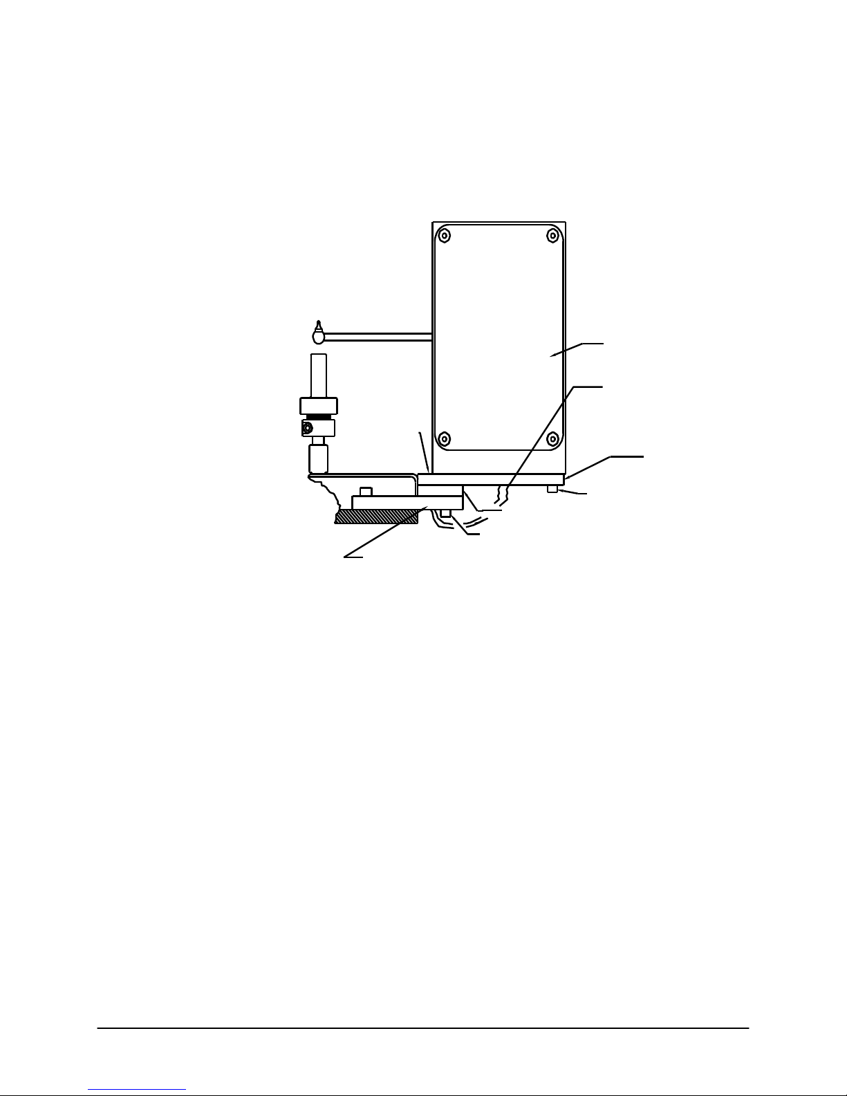
Pneumatic lift setup
*** Be sure to enable the following features in the SETUP Mode ***
(Please refer to drawing below)
a.) Find the safety spike
shipped in the down position. Remove the spike from the post and mount it into
the aluminum weight bucket
bottom of the weight bucket. Tighten set screw
b.) Loosen the guide block set screws
the guide post
block. Tighten the guide block set screws
c.) Connect a length of tubing (supplied) to the main solenoid valve
Push the tubing into the brass fitting and pull it to seal. Attach shop air supply
(60 psi) to the other end of the tubing. Be sure to incorporate a water trap in the
air line.
(2)
up until the bottom snap ring touches the bottom of the guide
(1)
taped to the guide post
(3)
as shown. The spike should be flush with the
(5)
with a 3/32” hex wrench and slide
(5)
.
(2)
. The guide post is
(4)
with a 1/8” hex wrench.
(6)
.
d.)
(8)
is the low voltage solenoid switch which controls the UP and DOWN
functions via signals from the Indexer. The main solenoid valve
pressure to the appropriate cylinder for UP and DOWN movement. Switch
Installing the Digital Encoder
Series 4000 Melt Indexer Operation Manual Getting Started 7
is an extra safety “lock” feature that will lock the lift in place if closed.
The following parts should be in the encoder upgrade kit or included with the
encoder based melt indexer: (if ordered)
Two 1.25" long #8-32 Socket Head Cap Screws (SHCS)
Two 5/8" long #8-32 Socket Head Cap Screws
Two 5/8" long #8-32 Reduced Head Socket Cap Screws
Six #8 Lock Washers & Four #8 Washers
One Encoder Housing
One Long Plate, Plate #1
(6)
directs air
(7)
Page 16
One Small Plate, Plate #2
Installation Steps (See Figure 1);
1. Using two 5/8 " Reduced Head Socket Cap Screws & two #8 Lock Washers,
attach plates #1 & #2 to plate #3 (plate #3 is already attached to the MI).
Tighten the screws.
Two Reduced Head
#8-32 x 5/8" Long
Socket Cap Screws &
Two Lock Washers
Plate #2
Figure #1
Plate #3 (Already Mounted to MI)
Two #8-32 x 1.25" SHCS
Two Washers & Lock Washers
Encoder Housing
Phone Jack Cable
Plate #1
Two #8-32 x 5/8" SHCS
Two Washers & Lock Wash
2. Attach the Encoder Housing to the long plate (plate #1) using two 1.25" long
SHCS, two 5/8" long SHCS, 4 washers & 4 lock washers (washers first then
lock washers, i.e. lock washers under screw head).
Note for Pneumatic Lift Users: With the encoder arm in the down position,
lower the pneumatic lift. Move the arm up and down to check for clearance
with the pneumatic lift bucket. Clearance may be increased a small amount by
rotating the encoder housing before tightening the screws. If no clearance
exists and the arm hits the pneumatic lift bucket, contact Dynisco Polymer Test
before proceeding.
Tighten the screws
3. Plug the phone jack cable into the encoder housing.
4. Move the encoder arm into the down position.
5. Turn the power on.
6. Enable the Encoder by pressing the SETUP key. Browse the options until
you reach B FLAG and press EDIT. Press —› Quick Key so that ENCODR is
over the SELECT Quick Key. SELECT ENCODER and press ENTER to
accept. Press ESC to back out to the main menu.
Series 4000 Melt Indexer Operation Manual Getting Started 8
Page 17

7. Press the SYS key and select TEST. Browse the menu and select Digital
Encoder Test. The display shows current position and should change when the
arm is moved. Press QUIT ending the procedure. ESC out to main menu.
8. See section entitled for detailed instructions on the variety of uses and
RTD Connection
Printer Connection
Computer Connection
Power Cord
Series 4000 Melt Indexer Operation Manual Getting Started 9
Options:
programming available with the encoder option.
The RTD, or thermocouple, is buried inside the instrument's barrel. The RTD
and associated temperature control electronics are calibrated against NIST
traceable temperature probes at Dynisco Polymer Test Systems. To achieve
accuracy required by ASTM D1238 the RTD and electronics control should be
kept together. Changing a RTD requires a complete temperature re-calibration.
Please consult the factory when required to replace the RTD.
Connect the power cord to the melt indexer. There may be a number of standard
power cords supplied; the heaviest is used for the melt indexer. The factory
suggests using a noise filtering outlet strip to connect the instrument and
associated components to the power source.
Connect the printer (if you have one) to the melt indexer. A cable is provided
with two distinctly different ends; one connects to the printer and the other to
the melt indexer. The connections are on the back sides of both machines. Be
sure the printer is OFF when connecting the indexer.
The data processing system (4004 models only) consists of a PC and the
MIWORKS software package . If your melt indexer is so configured, you will
find the proper cable included with the equipment. The cable will connect to
COM 1 on the computer side and to the smaller connector on the back of the
indexer. Set COMM PORT to PC under the SYSTEM key on the indexer.
Refer to the MIWORKS software manual for more details.
If system purchased after February, 2012, the system will only have a USB
connection. Please see “Setting-Up USB Connections” section of this manual.
The Series 4000 melt indexer has various options to make conducting specific
measurements easier, or make running multiple samples faster and more
convenient. As previously described, the Melt Indexer maybe shipped with a
Digital Encoder, a Pneumatic Lift System or a Mini-Lift system. The
installation of these options is described in the appropriate Appendix of this
manual.
Page 18

Safety
Use gloves, it's HOT!
To prevent burns, gloves and a long sleeve shirt (or lab coat) are essential. Dies
and piston rods are extremely hot and are designed to quickly transfer heat to
the sample being tested. Unfortunately this means they will transfer heat very
quickly to you as well. Even brief contact with a hot item can cause a burn. The
indexer barrel housing can also get fairly hot, however, at barrel temperatures
lower than 350 C these will not cause burns if touched for a brief period.
Consider where dies may fall. If they are dropped on Nylon carpeting or similar
materials they can quickly form holes. Protective mats may be needed.
DYNISCO POLYMER TEST recommends keeping a hot piston rod in the
chamber; this precludes someone picking it up inadvertently. Be sure to hold
the piston by the top insulator.
Electrical Hazard
Your Dynisco Polymer Test indexer contains high voltage inside the steel
housing. DO NOT remove the housing unless you are instructed to do so by a
DYNISCO POLYMER TEST representative or are experienced with high
voltage devices. Be sure the outlet used to power the indexer is properly
grounded.
Calibration Thermometers use
Mercury
To calibrate the temperature on the indexer, a thermometer containing about 8
grams of mercury is used. Every lab with mercury thermometers or equipment
containing mercury must be prepared for breakage. Note that mercury exposed
to air "evaporates" at room temperature, producing an invisible, tasteless,
odorless and dangerous vapor. Thermometers have been used for decades in
laboratory equipment and when used properly provide an accurate and effective
means of calibration. Keep the thermometer in a safe place where it will not be
crushed or otherwise broken. When using the thermometer be careful not to
drop or bend the glass. Place a hot thermometer onto cotton patches to cool .
Never put a hot thermometer in contact with cold metal or cold solvent because
the thermal shock can crack or shatter the glass. Mercury is extremely toxic and
should be handled accordingly.
A material safety data sheet (MSDS) for mercury (Hg) can be found in the
appendix. Observe local, state and federal hazardous waste disposal laws when
disposing of any broken thermometers. If packaged in a sealed plastic container
Series 4000 Melt Indexer Operation Manual Safety 10
and labeled with the following symbol:
Page 19

Broken thermometers and their spilled mercury can be sent back to the
manufacturer. UPS will accept these packages provided they are labeled and the
material is in a secure container. See Princo support vendor for address
information.
Pinch Points
Do not place weights in precarious positions where they can be bumped and fall
to the floor. For large weights (over 10 kg) the pneumatic lift system is
recommended. In using a pneumatic lift system for weights up to 21,600 gram,
the safety pin (spike) that goes through the weights must be used. When the
machine is in operation the lift system moves the weight downward quickly
creating an area where anything lying beneath could be crushed. Press the UP
and DN keys only when the areas above and below the weight are clear.
Fumes from Materials
Plan for the unexpected when it comes to materials giving off hazardous vapors.
Many polymers (PVC, PVF etc.) are well known for giving off hazardous fumes
at elevated temperatures. An exhaust system that removes fumes from both the
die exit and near the top of the barrel is strongly recommended. Consideration
should also be given to additives that may degrade or decompose at elevated test
temperatures.
Pre-Run Check List
The following points should be addressed before running the instrument for the
first time:
120V power outlet properly grounded? (230 V Europe/Asia)
Indexer level and on a sturdy bench?
Protective oil wiped out of barrel?
Exhaust hood or snorkel working?
Arm protection, long sleeves or lab coat
Operator using high temp gloves?
Series 4000 Melt Indexer Operation Manual Safety 11
Operator using safety glasses?
Page 20

Series 4000:
A Guided Tour
Overview
Setup
Edit
Series 4000 Melt Indexer Operation Manual Series 4000: 12
Run
System
Four Options from the main menu
screen.
The Series 4000 Melt Indexer has been designed for ease of use. The VFD
display prompts the user for input necessary to program, configure and run the
instrument. From the main menu screen, the user has the choice of four
instrument routines. The user may:
Configure the Instrument (by pressing the SETUP Key)
Edit a Program (by pressing the EDIT Smartkey)
Run a Program (by Pressing the RUN Smartkey)
Enter Calibration and Test Routines (by pressing the SYS key)
It is important that the instrument first be properly configured. This involves
pressing the SETUP key and checking instrument options and units for
particular parameters
Melt Index experiments (particularly method A tests) rely on the instrument to
reach the proper temperature and (in method B and A/B tests) collect
information on the travel of the plunger. The user is first expected to input the
appropriate parameters for the experiment and subsequent calculations in the
EDIT routine. After this is accomplished, the user may RUN the program.
The melt index unit relies on the operator to properly program the unit, load the
sample, start the experiment, wait the appropriate length of time, and (in method
A tests) collect the sample to weigh. All tests require that the instrument be
properly cleaned between runs
Many calibrations can be performed in the SYS, CALIBRATE mode. Although
the unit is not expected to change calibration values over years, it is always wise
Page 21
to check the previous values. Maintenance should typically be performed on our
instruments every 6 months. Your lab procedures may be different.
Each of these instrument routines is covered in greater detail in the following
sections. Before the user attempts to work with the instrument, it is important to
become familiar with the keyboard itself and the keystrokes necessary to
perform particular functions.
Navigating the Keypad
Introduction
Series 4000 Melt Indexer Operation Manual Series 4000: 13
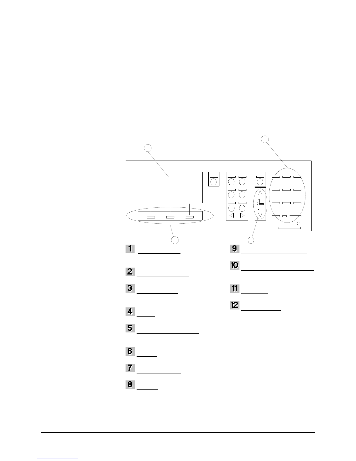
The Keypad
The keypad provides all of the means necessary for programming the Dynisco
Polymer Test Melt Indexer (Unless it is connected to a PC.) Other functions that
can be performed on the keypad include calibration, instrument tests, parameter
setups and pneumatic lift controls.
10
11
12
ESC (ESCAPE) - Backs out
one level from any mode. Quits a
test totally
PROG (PROGRAM) - Browse
and select a preprogrammed program
SYS (SYSTEM) - Enter self
calibration modes or hardware
diagnostic modes for testing unit.
SHIFT - Toggle between
numerical and alpha-numerical input
ID (IDENTIFICATION) -
Enter operator and sample
identifications
SETUP - Change system
parameters
LIFT UP/DOWN - Raise and
lower pneumatic lift(s) if equipped
CLEAR - Clears present value
in editing modes
ESC PROG SY S
1 2 3 4
ID SETUP
6
CLEAR BACkSP
98
Destructive backspace
Allows for numerical and alpha
numerical character input.
display
used for browsing, selecting and
entering values and parameters
SHIFT ABC 7 DEF 8 GHI 9
JKL MNO4 5 PQR 6
kg STU VWX1 2 YZ 3
*-# 0 .
ENTER
7
BACKSP (BACKSPACE) -
NUMERAL/ALPHA INPUT -
DISPLAY - 4 X 20 instrument
SMART KEYS - Main Keys
Page 22

Keypad Definitions
ESC (ESCAPE)
The ESC key can be used in any screen. During an EDIT function, ESC backs
out one level. During a sample run, ESC aborts the test.
PROG (PROGRAM)
Pressing the PROG key lets the user browse through a list of preprogrammed
test parameters. From this mode the user can browse through a list of programs
by using the UP or DOWN SMART KEY button and then select the desired
program by pressing the ACTIVE SMART KEY button.
SYS (SYSTEM)
In this mode the user can choose to calibrate, test or quit by selecting the
appropriate CALIB, TEST or QUIT SMART KEY, respectively.
*** Depending on what instrument model you have, prompts may vary ***
CALIB- Select either Digital Flag, RTD Electronics, RTD Sensor, Optical
Flag or IV Offset calibrations by toggling prompt with UP or DOWN QUICK
KEYS and using SELECT to start the calibrations. Please reference
Configuring the Instrument sections (Page ) or Appendix # for more
detailed operations of calibrations.
TEST- Select either RTD Display, Digital Encoder, Printer or Display
Brightness tests by toggling prompts with the UP or DOWN SMART KEYS
and using SELECT to start the test. Please reference Configuring the
Series 4000 Melt Indexer Operation Manual Series 4000: 14
Instrument sections (Page ) for more detailed operations of tests.
SHIFT
The shift key is used when inputting numeric and alphanumeric characters in the
sample, operator or program identification screens. Pressing SHIFT, then the
appropriate numeric/alpha key enters the alpha input mode. This mode provides a
selection of alpha characters above the SMART KEYS that correspond to the
numeric/alpha key pressed. When in the alpha mode it is not necessary to press
the SHIFT key to select alpha input every time. Just press the appropriate
numeric key to select different alpha characters. Press SHIFT to re-enter the
numeric input mode.
ID (IDENTIFICATION)
Define your operator and sample identifications for each program by pressing
the ID keypad. Toggle between operator and sample by pressing the right
SMART KEY . Press the ENTER SMART KEY to enter a new identification for
the desired parameter.
SETUP
Setup provides a series of system settings pertaining to your test. After pressing
SETUP, scroll through the list of settings using the UP or DOWN SMART
KEYS . Select the EDIT SMART KEY to change the parameter accordingly.
Please reference Configuring the Instrument Section for a detailed description
of each parameter
LIFT UP/DOWN
If your instrument is equipped with the Pneumatic lift option, these keys will
manually operate them.
CLEAR
Page 23

The CLEAR key will clear any active value displayed in the EDIT PROGRAM
mode (EDIT SMART KEY then EDIT SMART KEY again) or any text entry.
The clear key will also clear the PROGRAM number in the VIEW PROGRAM
mode (EDIT SMART KEY) where a new program number can be entered.
BACKSP (BACKSPACE)
The BACKSP key performs a destructive backspace function in text editing
screens.
NUMERAL/ALPHA INPUT
Using combinations of the SHIFT key and the NUMERAL/ALPHA INPUT
keys, either numbers or letters can be entered in the SAMPLE, OPERATOR and
PROGRAM identification modes. Pressing SHIFT then the appropriate
numeric/alpha key enters the alpha input mode. This mode provides a selection of
alpha characters above the SMART KEYS that correspond to the numeric/alpha
key pressed. Press SHIFT to re-enter the numeric input mode.
A space can be entered by pressing the 3, YZ keypad.
DISPLAY
Your instrument uses a 4 line vacuum fluorescent display, VFD, to display
information. Brightness can be adjusted in the SYSTEM TEST mode.
SMART KEYS
Dynisco Polymer Test provided three keypads below the VFD, to allow for
quick navigation of the machine interface. The functions of these keys change
depending on the mode of operation. Each SMART KEY is clearly and
concisely labeled to assist you in programming your instrument.
Configuring the
Instrument
Series 4000 Melt Indexer Operation Manual Configuring the Instrument 15
Intro: The SYS (SYSTEM) Mode
Many functions can be performed on the instrument using its operator interface.
Hardware calibrations, tests and option configurations will be discussed in this
section.
The system mode lets the user perform calibrations or hardware tests. The
system mode is entered by pressing the SYS keypad. For complete information
on the keypad and its function's reference Navigating the Keypad Sections in
the manual. Once you have entered the CALIBRATE and TEST Select mode
you can select between calibrate and test.
Page 24

Selecting CALIB (Calibration) in the
SYS Mode
CALIB:Digital Flag Home
CALIB:RTD Electronics
CALIB:RTD Sensor
CALIB:Optical Flag
CALIB:Intrinsic Viscosity Offset
Series 4000 Melt Indexer Operation Manual Configuring the Instrument 16
The Digital Encoder is calibrated at Dynisco Polymer Test prior to shipment.
Because the arm is locked into place, calibration is rarely required.
The instrument does allow you to reset the home position of the encoder.
If calibration needs to be checked due to suspected encoder damage, then
contact Dynisco Polymer Test for assistance and the necessary tool kit.
Please reference the section entitled “Instrument Calibration”
for further details on actual calibrations.
The RTD electronics are calibrated at Dynisco Polymer Test prior to shipment.
Please do not reconfigure this option.
Please reference the section entitled “Instrument Calibration”
for further details on actual calibrations.
Calibration of the RTD Sensors requires one or two thermometers or equivalent.
The RTD sensor is calibrated at Dynisco Polymer Test prior to shipment.
There should be no need to re calibrate the RTD sensor.
Please reference the section entitled “Instrument Calibration”
for further details on actual calibrations.
The instrument allows for the adjustment of the Optical Flag sensitivity. This
determines how sensitive the Optical Flag LED Receiver is in either of two
states, blocked or open. Sensitivity directly affects the measured length of the
tape flag.
The Optical Sensor is calibrated at Dynisco Polymer Test prior to shipment.
There should be no need to re-calibrate the Optical sensor. For this procedure
you must have the Flag Calibration Unit (Factory Part # D2044).
Please reference the section entitled “Instrument
Calibration” for further details on actual calibrations.
The IV offset is the difference between the computed IV and the experimentally
obtained IV. If option available, enter the difference here for correlation during
IV runs. See the I.V. section.
Please reference the section entitled “Instrument Calibration”
for further details on actual calibrations.
Page 25

Selecting TEST in the SYS Mode
TEST:RTD Display
TEST:Digital Encoder
TEST:Printer
TEST:Display Brightness
Introduction
REJECTION
Series 4000 Melt Indexer Operation Manual Configuring the Instrument 17
AVERAGE
MFR / MVR
B FLAG
VISCOSI
TY
PRINTE
R
FORM FEED
Press SELECT to view actual temperature reading accurate to 1/100 of a degree
Celsius. Dynisco Polymer Test technical support may have you do this under
certain conditions. RTD Display Test may also come in handy when
equilibrating RTD’s and thermometers.
Displays the current digital encoder arm position. Readings for home position
should be 105.00 mm, +/- 1.5 mm.
Your model must support printer output to perform this test. A test pattern
output will be produced on the connected printer. Press STOP to end printer
output.
The operator can control the VFD brightness level. Select a percentage of
default brightness.
The SETUP mode
This software routine is used to set user preferences for data collection. This
routine also turns off instrument options such as the digital encoder or pneumatic
lift. Please scroll through the settings prior to commissioning the instrument and
make a note of the values particular to your instrument. If for some reason the
settings are changed or erased they can be easily re-entered from this menu. By
pressing the SETUP key the following series of inputs are requested of the user.
Press the ENTER SMART Key to input the appropriate value. After entry is
complete, press the ESC key to save modified information.
After pressing SETUP, scroll through the list of settings using the UP or
DOWN SMART KEYS . Select the EDIT SMART KEY to change the parameter
accordingly. Please reference Configuring the Instrument Section for a
detailed description of each parameter. Note the order the items appear can vary.
[1..5, OFF] ] Exclude data points that are more than the operator entered
number of standard deviations from the mean. Exclude these points from all
statistical calculations. Points are not deleted but marked on the printouts with
asterisks. The rejection option is used for systems configured with a printer.
Data points are printed but not included in statistics.
[AUTO, OFF, ON] ON: average is computed for one or more data collection
runs. Generates statistics for printout. AUTO: compute the average of a single
data collection run without operator interaction at the end of the run.
[MFR or MVR] The operator can choose the calculated result. The choices are
Melt Flow Index or Melt Volume Index respectively.
[ENCODR or FLAG] Enable either the Digital Encoder or the Optical Flag
devices, respectively.
[POISE, PA-S, REYN] Select units of viscosity for displayed results.
[MINI, OFF, EPSON, IBM, LASER] Select output device. Mini printer, No
device, Epson compatible, HP Laser Jet compatible, respectively. (Only 4002
models will have the mini-printer option)
[OFF or ON] Perform a Form Feed (A page is sent out of the printer) after the
run data is printed.
Page 26

COMM PORT
MINI LIFT
PNEU LIFT
LOCKOUT
DATE and TIME
MACHINE ID
LANGUAGE
ORIFICE DIA
ORIFICE LEN
Introduction
Create (New)
Recall (Old)
Save Program
While EDITING
[ PC, OFF, DIAG] Open up communications port for computer output, no
output or diagnostics mode, respectively.
[OFF or ON] Enable the mini lift to function during material runs when
installed.
[OFF or ON] Enable pneumatic lift to function during material runs, when
installed.
[OFF or ON] Enable password protection. When ON users can not edit test or
system parameters only run tests. The default password is 1234, if the
LOCKOUT is enabled this number must be put in to turn the LOCKOUT off.
The NUMBER item allows a new password number to be entered.
Set the appropriate date and time here. Follow prompts.
[##] Assign a unique machine number to the instrument. If using MIWORKS
be sure this is set to one if you have only a single machine or to the Porter box
port number for multiple machines. This allows you to tell what machine your
sample was run on when you have more than one machine.
[CUSTOM, ENGLISH, FRENCH, ITALIAN, SPANISH, GERMAN] Switch
between desired languages.
[XXX] Store standard orifice diameter, 2.096 mm. Used in calculations.
[X.XXX] Store standard orifice radius, 8.000 mm. Used in calculations Scroll
through this menu and make appropriate changes. Press ESC twice and any
changes that have been made will be implemented.
Programming
This section is intended for a quick reference of method parameters. Please refer
to the appropriate sections in the manual for more specific information about a
particular method.
Before a measurement can be made, the RUN PARAMETERS must be
entered. These parameters dictate how the experiment will be performed. Many
of these parameters are set by particular ASTM test procedures. The SERIES
4000 software has many of these values pre-loaded into memory.
Press the EDIT SMART Key to start the EDIT mode. Enter the new program
number into the upper left hand corner of the display and press ENTER.
Proceed to EDIT.
Press the PROG button and enter the program number in the upper left hand
corner of the display or BROWSE with the Smart Keys. Press ACTIVE to use
the selected program number.
From the EDIT mode, ESC out until prompted to SAVE PROGRAM. Select
SAVE to save. In order to receive the SAVE PROGRAM prompt, a value
must be changed while in the editing mode.
Browse the suggested values appearing on the 3rd line of the Edit Screen with
the
SMART Key (Browse Key). Select the desired value with the
Series 4000 Melt Indexer Operation Manual Configuring the Instrument 18
Page 27

SELECT SMART Key. Accept the value with the ENTER SMART Key. The
user always has the option to enter values manually via the numeric keypad.
Below is a listing of the run parameters that are required for each test method.
Method A Run Parameters
METHOD = [A, B, A/B or RATIO] SELECT and ENTER Method A.
SET POINT = [Temp. Celsius] Dependent on the material, ASTM
requirements. Enter or Select value using browse key .
MELT TIME: [Time, Seconds] ASTM D1238 equilibration time for most
materials. Enter or Select value using browse key .
CUT TIME =[Time, Seconds] This is the sample collection time, the length of
time an extrudate sample is squeezed out. Enter or Select value using browse
key. Dependent on Flow Rate characteristics.
NO OF CUTS =[Number] Dependent on material - up to 5 cuts allowed
LOAD =[Weight, Grams]. Mass of weight plus piston assembly, ASTM
requirements
QC LIMITS [On or Off] Allows QC limiting of data to be used
QC Limits High [Number] Highest MFR limit saved
QC Limits Low [Number] Lowest MFR limit saved
PROGRAM ID [Characters] Name of program up to 14 characters long
METHOD = [A, B, A/B or RATIO] SELECT and ENTER Method A/B.
SET POINT = [Temp., Celsius] Dependent on the material, ASTM
Method A/B Run Parameters
requirements. Enter or Select value using browse key .
MELT TIME: [Time, Seconds] ASTM D1238 equilibration time for most
materials. Enter or Select value using browse key .
CUT TIME =[Time, Seconds] This is the sample collection time, the length of
time an extrudate sample is squeezed out. Enter or Select value using browse
key . Dependent on Flow Rate characteristics.
FLG LENGTH =[Length, millimeters] Flag length in millimeters. Dependent
on Melt Flow Rate. Digital Encoder equipped instruments will be asked further
questions. Reference Digital Encoder Section in manual.
LOAD =[Weight, Grams] Mass of weight plus piston assembly, ASTM
requirements
PROGRAM ID [Characters] Name of program up to 14 characters long
METHOD = [A, B, A/B or RATIO] SELECT and ENTER Method B.
Method B Run Parameters
SET POINT = [Temp. Celsius] Dependent on the material, ASTM
requirements. Enter or Select value using browse key.
MELT DENSITY =[X.XXX,g/cm³] Numeric value, calculated from A/B Run.
MELT TIME: [Time, Seconds] ASTM D1238 equilibration time for most
materials. Enter or Select value using browse key.
Series 4000 Melt Indexer Operation Manual Configuring the Instrument 19
Page 28

NO FLAGS: [X] Stands for Number of Flags. Enter the number of stripes on
your flag. This applies only to units with an optical eye for type B and A/B
measurements. This step is different for users with a digital encoder. Please
reference Digital Encoder Section.
FLG LENGTH =[Length, mm] Flag length in mm for Optical Eye Instruments.
Dependent on Melt Flow Rate. Digital Encoder equipped instruments will be
asked further questions. Reference Digital Encoder Section in manual.
LOAD =[Weight, Grams] Mass of weight plus piston assembly, ASTM
requirements
QC LIMITS [On or Off] Allows QC limiting of data to be used
QC Limits High [Number] Highest MFR limit saved
RATIO (Flow Ratio) run parameters
Series 4000 Melt Indexer Operation Manual Configuring the Instrument 20
QC Limits Low [Number] Lowest MFR limit saved
PROGRAM ID [Character string up to 14 characters long]
METHOD = [A, B, A/B or RATIO] SELECT and ENTER RATIO.
SET POINT = [Temp. Celsius] Dependent on the material, ASTM
requirements. Enter or Select value using browse key.
MELT DENSITY =[X.XXX, g/cm³] Numeric value, calculated from A/B Run.
MELT TIME: [Time, Seconds] ASTM D1238 equilibration time for most
materials. Enter or Select value using browse key.
FLG LENGTH =[Length, mm] Flag length in millimeters for Optical Eye
Instruments. Dependent on Melt Flow Rate. Digital Encoder equipped
instruments will be asked further questions. Reference Digital Encoder Section
in manual.
FLG LENGTH HIGH =[Length, Inches] Flag length in millimeters for second
flag strip.
LOAD =[Weight, Grams] Mass of weight plus piston assembly, ASTM
requirements
LOAD HIGH =[Weight, Grams] Mass of weight plus piston assembly of
second weight, ASTM requirements
PROGRAM ID [Character string up to 14 characters long]
Run a Program
Runs are initiated from the SMART key panel after your run parameters have
been properly set. Press RUN on the SMART keys. Each test method has a
different set of test protocols. Please refer to the further manual sections for
more specific information about a method.
Page 29

Method "A" Run
General Description
Calculations: Method A
Series 4000 Melt Indexer Operation Manual Method "A" Run 21
Power-Up
Introduction
Method A test involves collecting extrudate from the instrument over a fixed
period of time, then converting the result to grams/10 minutes. After the melt
time is over, a sample is collected by first cutting the extrudate across the orifice
face, then waiting a predetermined amount of time and then making a second
cut. (It is often very inconvenient or even impossible to wait 10 minutes) . The
sample is weighed and the flow rate is converted to grams of flow that would
have occurred over 10 minutes. Test temperatures can be obtained from the
manufacturer, from tables in ASTM D1238 or through experimentation.
Materials with Melt Flow Rates below 50 g/10 min. are generally done using
Method A.
Calculations for the Method A test are straightforward
MFR
where M is the mass in grams of material collected over time T in seconds. The
MFR value has units of g/10 min. (grams/10 minutes).
The instrument is turned on by throwing the switch located on the rear right top
corner of the instrument (as one faces the instrument). Toggle the switch to the
right and the unit will power-up.
The large, friendly VFD display will power up and display system information
as follows:
The instrument will beep twice after this screen. At that point, the screen will
refresh and the main menu screen will be displayed.
M 600
T
Melt Indexer Serial Number XXXXXX
Model Number 400X Ver 1.01
(c) DYNISCO POLYMER TEST, 1999
PROG # TEMPERATURE TIME
METHOD PROGRAM NAME
STATUS
EDIT RUN
Programming a Method A
The instrument is powered-on and the main menu screen is seen. If you plan to
use an existing method A program skip to step 4
NOTE: The unit will load the last program run into memory and attempt to
equilibrate the barrel temperature to that set-temperature.
Page 30

Machine Setup
Series 4000 Melt Indexer Operation Manual Method "A" Run 22
1) Press the EDIT SMART Key. -
The square cursor blinks in the upper left-hand corner of the screen prompting
the user to input the number of the program that will be created or edited.
2) Enter 05 (for example) and press ENTER on the numeric keypad.
The method in program 05 will now be configured for a method A experiment.
Press the center EDIT SMART Key to confirm. You can press ENTER to edit
the existing program or input a new program number to create a new program.
3) Enter Run Parameters
The user will now be prompted to enter the run parameters for the method A
experiment. The 2nd line of the VFD display displays the parameter to be
edited. The 3rd line lists a group of suggested values. The bottom line of
SMART Keys is used to ENTER, SELECT or SCROLL data input,
respectively.
METHOD =
Press the
over the SELECT SMART Key.
Press the SELECT SMART Key to select the method A test. The second line
should now read METHOD = A
Press SELECT/ENTER to accept and move to the SET POINT.
SMART Key (browse) until the 3rd line of the display has the A
SETPOINT =
The user may enter a temperature on the numeric keypad and press enter or use
the ENTER, SELECT and SCROLL SMART Key keys to choose a typical
value.
Press SELECT/ENTER to accept the value and move to the MELT TIME
MELT TIME =
The user may enter a melt time from the numeric keypad and press enter or use
the Enter, Select and Scroll SMART Key keys to choose a typical value
Press SELECT/ENTER to accept the value and move to the NO OF CUTS
NO OF CUTS =
The user must enter the number of cuts from the numeric keypad and press
ENTER to accept the value and move to the LOAD screen.
LOAD =
Enter the LOAD from the SMART Keys or from the numeric keypad. Pressing
ENTER then enters the QC limits screen.
QC LIMITS =
If YES is entered, the user is prompted to enter the HI and LOW QC limits from
the numeric keypad. Please reference "Edit a Program" section for descriptions
of HI/LOW QC Limits. Pressing ENTER then prompts the user to enter the
PROGRAM ID.
PROGRAM ID =
Enter the program ID and press ENTER when finished. Numeric and
alphanumeric values may be input. See "Navigating the Keypad" for more
information on alphanumeric input.
At this point, the screen will return to the EDIT Program METHOD = ? screen.
All data has been input at this point. Press ESC. The program can be verified
Page 31

at this point by pressing the UP or DOWN SMART Keys. This ends the
program edit mode.
To SAVE the program: Press ESC twice to back out to the SAVE Program
mode and select SAVE to save the program under the OLD program name.
Change the program name in the EDIT mode.
4) Choosing the Program
Press the PROGRAM button. A square block will appear in the upper left
corner of the LED display. Enter the number of the program that was just
created (05) or the number of the previously entered program of your choice.
You can also press UP and DOWN to browse preprogrammed programs.
The unit will then attempt to latch into the specified temperature. MAKE SURE
THE PISTON and DIE are in the unit. The temperature must equilibrate with the
assemblies in place. The user must wait until the specified temperature has been
achieved to continue with the experiment. When the instrument has latched-in,
continue with sample loading as follows:
Loading the Barrel
Series 4000 Melt Indexer Operation Manual Method "A" Run 23
Bubbles
RUN
Loading the Sample
Remove the piston rod and lay it on a cotton cloth. Check to see if the die is at
the bottom of the barrel. Fill the 10 ml beaker with an accurately weighed
charge of material (see section on Charge Weight). Fill heat chamber with this
appropriate charge. Use about 5 grams if nothing is known about the material.
Add about two-thirds of the beaker into the barrel, using the brown fill funnel.
The loading should be done in two increments, the first consisting of
approximately 60% of the material. Tamp down the material with the packing
tool using approximately 20 pounds of force. The packing tool can be inserted
through the fill funnel. If bridging (clogging-up) of the material occurs in the
fill funnel, slide the fill funnel off to one side (without lifting) and tamp down
on the material in the barrel. Move the fill funnel back into place. The
remaining material should drop down into the barrel directly. Repeat with the
remainder of the material.
Bubbles are in your sample if snapping/popping noises are heard as the
extrudate is forced through the die orifice. If bubbles appear in the extrudate
use less material between tamping down. If bubbles continue the sample may
not be sufficiently dry.
Place the plunger into the barrel. (Position the Optical Flag post to the right
side). Seat the guide bushing down into the barrel if it as not already fallen into
place. The guide bushing should move freely on the plunger. Place the weight
on the plunger rod and immediately press RUN. RUN must be pressed
immediately after loading the barrel to be compliant with the ASTM 1238
specification. Pressing RUN also starts the internal computer program running.
This program will start an internal timer. Wait for the melt time (pre-heat) clock
to count down from 360 seconds.
Page 32

Optical Flag Post
Plunger / Piston Assembly - Scribe Marks
Run Area Pre-Heat
Bushing
2nd Scribe 1st Scribe
After melt time (pre-heat) is completed, and after the piston lowers into the
"run area" as denoted by the scribe marks on the piston assembly, make a
cut and press RUN simultaneously. A measurement may start when the 1st
scribe mark has lined up with the top of the guide bushing. The run MUST
start before the 2nd scribe mark lines up with the top of the guide bushing.
See “Making the Cut” section. If the sample extruded so fast that it has
already passed the scribe marks the user has the following options:
Add more material
Reduce the test load (e.g. 2160 to 225 g)
Reduce the test temperature (e.g. 230 to 190 C)
Use a flow plug
Support the plunger and piston during melt time
Change to a non-standard die (e.g., 1/2 diameter, 1/2 height)
If the sample extrudate is so slow that the first scribe mark is not passed before
8 minutes has expired, the user has the following options:
Add less material
Increase the test load (e.g. 2160 to 21,600 g)
Increase the test temperature (e.g. 190 to 230 C)
Making the Cut
Series 4000 Melt Indexer Operation Manual Method "A" Run 24
Weigh the Sample
Change to a non-standard die (typically larger diameter)
When the lower scribe mark on the plunger reaches the top of the guide bushing
simultaneously cut the extrudate and press RUN. Use the cutting knife in a
wiping like action up against the bottom of the die. After pressing RUN a
countdown timer appears on the left of the front display. As it counts down it
will give a warning beep when 10 seconds remain in the cut time. When the
timer reaches zero and the machine beeps, quickly cut the extrudate up against
the bottom of the die.
Weigh the sample and enter the weight in grams using the touch panel and hit
YES if correct. (A precision balance is needed in order to obtain precise flow
rate measurements) The flow rate will be immediately calculated and displayed.
An extrudate weight of about 1.0 gram or more will reduce weighing errors,
adjust the cut time as needed to get at least 0.5 grams of material.
If the indexer has printing capability, flow rate will be printed along with other
test details. When multiple tests have been completed an average, standard
Run Start Zone
Page 33

deviation and coefficient of variance can be printed once, when the END key is
Cleaning Up
User Tip #1
User Tip #2
pressed.
Push down on the weight and purge any material remaining in the barrel.
Remove the rod by twisting it clockwise to break the seal created by the molten
plastic then pull straight up. Warning: If you pull the rod out too quickly you
may cause a suction that pulls the die out along with it. Wipe the plunger rod
with a cotton rag. Remove the die with the die removal tool and clean with the
appropriate cleaning tools. Put two patches directly over the barrel about 1/2
way overlapped. Using the cleaning tool, push the patch down into the barrel.
Run the patch up and down a half dozen times or so, then repeat the process.
The second set of patches should come out fairly clean, if not repeat the process
until they come out clean. When done, put the die and plunger back into the
barrel. This allows the plunger and die to heat up before the next test.
With materials that are thermally stable (less than 5% viscosity change over 1/2
hour) we recommend only cleaning the barrel between runs of the exact same
material. For materials that degrade or are moisture sensitive, we recommend
cleaning both the barrel and the die completely. To clean the die, use the die
removal tool to push the die up from the bottom of the barrel and out the top.
Wipe it with the cotton rag and clean it by running the drill bit through it several
times. Remove material that collects in the grooves of the drill bit and repeat
until the drill passes easily through the die. Scrape the die with the cutting knife
if needed to clean the top and bottom faces. For materials that crystallize
quickly, you can clean the die by first running a drill bit up into the die while it
is hot and in the indexer. This will make it much easier to get the cleaning drill
bit in when the die is removed and the material starts to solidify.
While the die is out, put on safety glasses and look down the barrel bore to be
sure it is clean. A clean barrel will have a mirror-like shine to it. If it is not run a
couple of patches up and down it before putting the die back into position.
User Tips:
Drop the die into the barrel and listen for it to double bounce off of the bottom
of the barrel. If the barrel is dirty, the die hangs up and will not bounce when it
hits the bottom of the barrel.
If you are using a PVC die (D3364 unstable materials) be sure to get the
material out of the conical top section. (standard dies have a flat entrance and
exit). .
When the die is out of the barrel it cools down quickly. The longer it is out, the
longer one must wait for the temperature to stabilize. Minimizing the time the
die stays out of the machine will increase the number of tests you can run.
When the temperature on the front display is within 0.2 C of the set point you
can begin your next test. Loading material will cause a small temperature
change even if the temperature steeping was locked in. The melt time (360
seconds) will allow ample time for the temperature to reach the steeping before
the first data point is collected.
Series 4000 Melt Indexer Operation Manual Method "A" Run 25
Page 34

Always leave the barrel clean.
Cleaning Up a really Big Mess
If it is going to sit at room temperature for an extended period of time you may
wish to coat the barrel with a light machine oil to prevent rusting. The oil will
need to be purged from the machine before accurate data can be obtained.
For materials that are extremely hard to clean (Polystyrene, EVA and
elastomers, etc.) solvents may be required. Never use flammable solvents on a
HOT barrel. In general however, DYNISCO POLYMER TEST does not
recommend using solvents for health, safety, and environmental reasons.
Oven cleaner (Easy-Off) sprayed onto a cold plunger and left overnight will
do an excellent job of cleaning degraded material off of the shaft, the outside of
the die and the die retainer plate. Be careful not to inhale oven cleaner vapors.
Series 4000 Melt Indexer Operation Manual Method "A" Run 26
Page 35

Method "A/B" Run
General Description
Calculations: Method A/B
Series 4000 Melt Indexer Operation Manual Method "A/B" Run 27
In a Method A/B test both a Method A test and Method B test are performed on
the same charge of material. The melt flow rate, derived from Method A, is
equated to the Method B flow equation and solved for apparent melt density. The
value in doing this test is obtaining a valid apparent melt density which can later
be used in a sole Method B test (no manual cuts of extrudate nor weighing) to
achieve results equivalent to Method A (operator must make manual cuts and
weigh sample).
R L
Method B MFR =
2
T
B
Method A MFR =
MT
=
LR
Where R= radius piston (cm), TB is time to traverse the Method B distance L
(sec), L = Method A length of flag (cm), M is the mass in grams of material
collected over the time TA in seconds. MFR has units of g/10 min. (grams/10
minutes). is called the apparent melt density and is defined by equating the
methods, the Method B flow rate must equal Method A.
This apparent melt density definition forces the two test methods to
agree. DYNISCO POLYMER TEST recommends taking an average of
apparent melt densities from at least five separate A/B tests on representative
samples of polymer. This average apparent melt density can then be used for
Method B tests to get Method A values without having to make cuts! It is called
an "apparent melt density" because it is actually a correlation coefficient that
forces Method A and Method B to agree. If there were no leakage past the
plunger tip and the extrudate were bubble free and few other minor factors were
taken into consideration then a true melt density could be assessed. All lengths
are in mm.
B
2
T
M600
T
A
600
Page 36

Series 4000 Melt Indexer Operation Manual Method "A/B" Run 28
Introduction
Machine Setup
Programming Method A/B
The instrument is powered-on and the main menu screen is seen. If you plan to
use an existing method B program skip to step 4
NOTE: The unit will load the last program run into memory and attempt to
equilibrate the barrel temperature to that set-temperature.
1) Start a new program by pressing the EDIT SMART Key. -
The square cursor blinks in the upper left-hand corner of the screen prompting
the user to input the number of the program that will be created or edited.
2) Enter a program number “#” and ENTER on the numeric keypad.
Now you are in the VIEW program mode of a new program. You can browse
the program parameters for EDITING by pressing the EDIT SMART Key.
3) Enter run parameters by pressing EDIT again.
The instrument is now in the VIEW Program mode starting with METHOD.
Press the EDIT SMART Key to set the run parameters to method A/B. The 2nd
line of the VFD display displays the parameter to be edited. The 3rd line lists a
group of suggested values. The bottom line is SMART Keys used to ENTER,
SELECT of SCROLL data input, respectively.
METHOD =
Press the
over the SELECT SMART Key.
Press the SELECT SMART Key to select the method A/B test. The second line
should now read METHOD = A/B
Press SELECT/ENTER to accept the value and move to the SET POINT.
SETPOINT =
The user may enter a temperature on the numeric keypad and press enter or use
the ENTER, SELECT and SCROLL SMART Key keys to choose a typical
value.
Press SELECT/ENTER to accept the value and move to the MELT TIME
MELT TIME =
The user may enter a melt time from the numeric keypad and press enter or use
the Enter, Select and Scroll SMART Key keys to choose a typical value
Press SELECT/ENTER to accept the value and move to the CUT TIME
CUT TIME =
The Method A part of the run needs to know the amount of time between
extrudate start and stop cuts to calculate the correct result. The user must enter
the time manually from the keypad or browse preset values. Press
SELECT/ENTER to accept the value and move to the FLAG LENGTH screen.
DENSITY =
Enter the predetermined Melt Density of your material. Press ENTER.
FLG LENGTH =
Enter or select the length of your flag. Remember, Method B is volume, using
distance traveled to acquire results.
SMART Key (browse) until the 3rd line of the display has the A/B
Page 37

LOAD =
Enter the LOAD from the SMART Keys or from the numeric keypad. Pressing
ENTER then enters the QC limits screen.
QC LIMITS =
If YES is entered, the user is prompted to enter the HI and LOW QC limits from
the numeric keypad. Please reference "Edit a Program" section for descriptions
of HI/LOW QC Limits. Pressing ENTER then prompts the user to enter the
PROGRAM ID.
PROGRAM ID =
Enter the program ID and press ENTER when finished. Numeric and
alphanumeric values may be input. See "Navigating the Keypad" for more
information on alphanumeric input.
To SAVE the program: Press ESC twice to back out to the SAVE Program
mode and select SAVE to save the program under the OLD program name.
Change the program name in the EDIT mode.
4) Choosing the Program
Press the PROGRAM button. A square block will appear in the upper left
corner of the LED display. Enter the number of the program that was just
created (#) or the number of the previously entered program of your choice. You
can also press UP and DOWN to browse preprogrammed programs.
The unit will then attempt to latch into the specified temperature. MAKE SURE
THE PISTON and DIE are in the unit. The temperature must equilibrate with the
assemblies in place. The user must wait until the specified temperature has been
achieved to continue with the experiment. When the instrument has latched-in,
continue with sample testing:
The Actual Run
How to do it: Step by Step
Series 4000 Melt Indexer Operation Manual Method "A/B" Run 29
Instrument Prep
Loading the Barrel
(Note that the standard Dynisco Polymer Test In-house test procedure section in
this manual is an abbreviated version of what follows)
Press EDIT and verify all entered program data values are correct. Make sure
all equipment has been properly cleaned. Insert piston rod and let the system
come to temperature and wait for temperature lock-in. Lock-in has occurred
when the display reads “READY”. Heat up and lock-in must occur with orifice
and piston rod in the heat chamber.
During heat up the program may be adjusted and the Operator. and Sample ID
can be entered by pressing the ID key.
Remove the piston rod and lay on a cotton cloth. Check to see if the die is at
the bottom of the barrel. Fill heat chamber with an appropriate charge or use
about 5 grams if nothing is known about the material). Put the sample into the
10 ml beaker. Add about two-thirds of the material into the barrel, using the
brown fill funnel. The loading should be done in two increments, the first
consisting of approximately 60% of the material. Tamp down the material with
the packing tool using approximately 20 pounds of force. The packing tool can
Page 38

be driven through the fill funnel. If bridging (or clogging)of the material
occurs in the fill funnel, slide the fill funnel off to one side (without lifting).
Pack the material in the barrel directly with the packing rod. Move the fill
funnel back into place. The remaining material should drop down into the
barrel. Repeat with the remainder of the material.
Bubbles are in your sample charge if a snapping/popping sound is heard as the
extrudate is forced through the orifice. If bubbles appear in the extrudate use
less material between packing. If bubbles continue, the sample may not be
sufficiently dry.
Place the plunger into the barrel and position the plunger arm directly over the
slot on the indexer cover. Seat the guide bushing down into the barrel if it as not
already fallen into place. The guide bushing should be moving freely on the
plunger. Place the weight on the plunger rod.
Run Area
Flag Post
Guide Bushing
One Inch Flag
Galaxy I Cut Away View
(Piston bushing not shown)
Electric Eye
Plunger for Method B and Method A/B Measurements
Inserting the Timing Flag
Insert the plastic flag down into the slot on the top right side of the indexer then
slide the flag onto the plunger arm through the flag hole. Make sure that the flag
does not touch the sides of the flag slot. Twist the plunger as needed to get it to
line up with the flag slot and slide the flag on the arm until it is in a vertical
position. Immediately press RUN. RUN must be pressed as quickly after
loading as possible to be compliant with the ASTM 1238 specification.
Pressing RUN also starts the internal computer program running. This program
will start an internal timer and will attempt to print initial test information to a
printer or PC if the devices are available. The start of the flag time should begin
between 6 and 8 minutes after the test starts or the test does not follow ASTM
protocol. Wait for the melt time clock to count down from 360 seconds.
When melt time is over a flag timer appears set at 0.000. When the front edge of
the black flag passes the optical eye the timer starts. If the sample extruded so
quickly that it has already hit the front of the flag prior to the melt time passing
one must either:
Add more material
Series 4000 Melt Indexer Operation Manual Method "A/B" Run 30
(without digital encoder module)
Page 39

Use a flow plug
Reduce the test load (e.g. 2160 to 225 g)
Reduce the test temperature (e.g. 230 to 190 C)
Support the plunger and piston during melt time
Change to a non-standard die (e.g., 1/2 diameter, 1/2 height)
The first two are typically used. If, on the other hand, if the sample extrudate is
so slow that you do not reach the flag before 8 minutes has expired you must
take one of the following actions:
Add less material
Increase the test load (e.g. 2160 to 21,600 g)
Increase the test temperature (e.g. 190 to 230 C)
Change to a non-standard die (typically larger diameter)
Since Dynisco Polymer Test flags start at the same position as the first
scribe mark, the amount of sample charge works for both Method A and Method
Making the Cut
Cleaning Up
Your data
Series 4000 Melt Indexer Operation Manual Method "A/B" Run 31
B testing.
When the lower scribe mark on the plunger reaches the top of the guide bushing
simultaneously cut the extrudate and press RUN. Use the cutting knife in a
wiping like action up against the bottom of the die. After pressing RUN, a
countdown timer appears on the left of the front display. As it counts down it
will give a warning beep when 10 seconds remain. Exactly when it reaches zero
and beeps cut the extrudate up against the bottom of the die, as before. Weigh
the sample and enter the weight in grams using the touch panel then press YES.
You may have to wait for the flag to traverse the photo eye for slow flowing
materials. A precision balance is needed in order to obtain correct flow rate
measurements. The flow rate and melt density will be immediately calculated
and displayed. A extrudate weight of about 1.0 gram or more will reduce
weighing errors, adjust the cut time as needed to get at least 0.5 grams of
material.
If the indexer has printing capability, flow rate will be printed along
with other test details. When multiple tests have been completed an average,
standard deviation and coefficient of variance can be printed once, when the
END key is pressed.
Clean up is the same as that for Method A.
Data will be displayed on the VFD or printed if you have the printer option.
Follow the prompts on the VFD to END or SAVE the run.
Page 40

Method "B" Run
General Description
Calculations: Method B
Series 4000 Melt Indexer Operation Manual Method "B" Run 32
Method B is an assessment of a material's flow characteristics based on the
volumetric displacement rather than weight of extrudate with time as in Method
A. Unlike Method A, no cutting and weighing of the extrudate is required to
perform a Method B test. Results from Method B test can be expressed directly
as Melt Volumetric Flow Rate (MVR) in ml/10 min. To relate the results of a
Method B run back to Method A, the apparent melt density must be known.
The determination of the apparent density is illustrated in the previous section
using Method A/B. Without the apparent melt density MFR cannot be
calculated using Method B. Some companies use MVR directly without ever
determining MFR.
The piston’s downward travel time is determined from a counter initiated by an
optical sensor or digital encoder. The LED senses an opaque flag on a
transparent tape hung off the top of the piston rod. With all Dynisco Polymer
Test Systems flags, Method A and B start in the same place. Flags may be 1/8,
1/4, 1/2, or 1". Multiple flags are discussed in later. Recently, Method B has
become the more common test because it is simpler to run and more precise for
routine analysis. In addition, the encoder system makes it possible to get as
many as 15 results from one run.
Where R= radius piston (cm), T is time to traverse the distance L (sec), L =
length of flag (mm), = apparent melt density of polymer (g/cc)
You should determine the melt densities for your material using your own melt
indexer. Variations in technique and difference in material grades can cause
differences from user to user. The following table of melt densities can be used
as a general guide if you get values which differ by more than 10% from these
chances are you are doing something incorrectly. Fillers, reinforcing agents etc.
tend to increase the melt density of the material. Notice that apparent melt
density is a function of temperature. In general the solid state density is a very
poor estimate of the melt density and should not be used.
Some typical Melt Densities
Flow rate for method B is computed as follows:
R L
MVR
MFR
2
600
T
Page 41
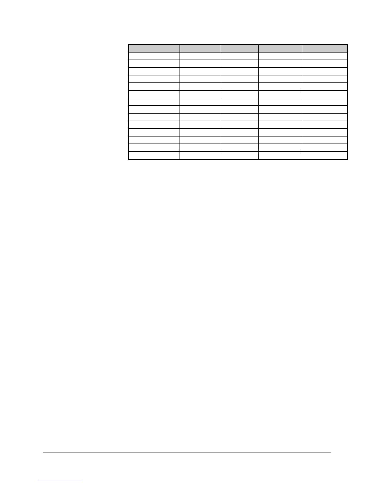
Temperature (C) LDPE HDPE Polybutene-1 polypropylene
120 0.797 -- 0.806 0.880
130 0.791 -- 0.800 0.872
140 0.785 -- 0.794 0.864
150 0.780 0.780 0.787 0.852
160 0.777 0.777 0.780 0.840
170 0.770 0.770 0.774 0.819
180 0.765 0.765 0.767 0.758
190 0.760 0.760 0.760 0.754
200 0.755 0.755 0.754 0.750
210 0.748 0.748 0.746 0.746
220 0.744 0.744 0.740 0.742
230 0.738 0.738 0.733 0.738
240 0.733 0.733 0.726 0.734
250 0.737 0.727 0.719 0.730
Any inaccuracies in the melt density will propagated proportionally along to the
MFR values. Thus a 1% error in the melt density means a 1% accuracy error in
the MFR the value.
Programming Method B
This is a Method B setup for use with optical flags, (Small plastic strips with a
black area), if you have and encoder based machine skip this section go to the
Method B Flags Setup
Series 4000 Melt Indexer Operation Manual Method "B" Run 33
"The Digital Encoder: Use and Calibration Chapter" Page 50.
1) Start a new program by pressing the EDIT SMART Key. -
The square cursor blinks in the upper left-hand corner of the screen prompting
the user to input the number of the program that will be created or edited.
2) Enter a number and ENTER on the numeric keypad.
Now you are editing a new program of number #. You can press the EDIT
SMART Key to edit the existing program and select a B Method test
3) After pressing EDIT SMART Key, enter run parameters by pressing
EDIT again
The instrument is now in the VIEW Program mode starting with METHOD.
Press the EDIT SMART Key to enter run parameters for the method B
experiment. The 2nd line of the VFD display displays the parameter to be
edited. The 3rd line lists a group of suggested values. The bottom line of
SMART Keys is used to ENTER, SELECT of SCROLL data input,
respectively.
METHOD =
Press the
over the SELECT SMART Key.
Press the SELECT SMART Key to select the method B test. The second line
should now read METHOD = B
Press SELECT/ENTER to accept the value and move to the SET POINT.
SMART Key (browse) until the 3rd line of the display has the B
SETPOINT =
The user may enter a temperature on the numeric keypad and press enter or use
the ENTER, SELECT and SCROLL SMART Key keys to choose a typical
value.
Page 42

Press SELECT/ENTER to accept the and move to the DENSITY
DENSITY =
Enter the predetermined Melt Density of your material. Press ENTER.
MELT TIME =
The user may enter a melt time from the numeric keypad and press enter or use
the Enter, Select and Scroll SMART Key keys to choose a typical value
Press SELECT/ENTER to accept the and move to the NO OF FLAGS
# OF FLAGS =
Method B runs can be made with multiple flags to observe the volumetric rates
of materials over different distances. The user must enter the number of flags
from the numeric keypad. Press ENTER to accept the value and move to the
FLAG LENGTH screen.
FLG LENGTH =
Enter or select the length of your flag. Remember, method B is volume, using
distance traveled to acquire results.
LOAD =
Enter the LOAD from the SMART Keys or from the numeric keypad. Pressing
ENTER then enters the QC limits screen.
QC LIMITS =
If YES is entered, the user is prompted to enter the HI and LOW QC limits from
the numeric keypad. Please reference "Edit a Program" section for descriptions
of HI/LOW QC Limits. Pressing ENTER then prompts the user to enter the
PROGRAM ID.
PROGRAM ID =
Enter the program ID and press ENTER when finished. Numeric and
alphanumeric values may be input. See "Navigating the Keypad" for more
information on alphanumeric input.
To SAVE the program: Press ESC twice to back out to the SAVE Program
mode and select SAVE to save the program under the OLD program name.
Change the program name in the EDIT mode.
4) Choosing the Program
Press the PROGRAM button. A square block will appear in the upper left
corner of the LED display. Enter the number of the program that was just
created (#) or the number of the previously entered program of your choice. You
can also press UP and DOWN to browse preprogrammed programs.
The unit will then attempt to latch into the specified temperature. MAKE SURE
THE PISTON and DIE are in the unit. The temperature must equilibrate with the
assemblies in place. The user must wait until the specified temperature has been
achieved to continue with the experiment. When the instrument has latched-in,
Choosing a Timing Flag
Series 4000 Melt Indexer Operation Manual Method "B" Run 34
continue with sample testing:
ASTM recommends two flags, a 1/4" and a 1" Flag. Use the longer 1"
flag for higher flow rates (> 10 g/10 min.) and the 1/4" flag for all others. The
aim is to have a flag long enough that the error in determining plunger speed is
Page 43

small resulting in precise flow rate measurements. Long flags for slowly
flowing material can make for extraordinarily long tests and the material may
actually degrade substantially during the test.
Dynisco Polymer Test provides 1/8" and 1/2" Non-ASTM flags in addition to
the standard 1/4" and 1" flags to provide more flexibility in the time needed to
traverse the flag (B time). Use the following table to aid your selection of the
proper flag.
Flag Selection Table
MFR MFR Flag Flag travel
Min Max Length Time Range
g/10m g/10m cm minutes
0.15 1.0 .635 29 - 4.
0.15 1.0 .3175 14 - 2
1.0 3.5 .635 4.3 - 1.2
1.0 3.5 1.27 8.7 - 2.5
3.5 10 0.635 1.2 - 0.4
3.5 10 1.27 2.5 - 0.9
10 25 1.27 0.9 - 0.4
10 25 2.54 1.8 - 0.8
25 50 2.54 0.8 - 0.4
50 300 2.54 0.4 - 0.06
From the first two lines 0.15 to - 1 g/10 min. expected MFR we can see we have
the option of running with a 0.635 cm (1/4") Flag or a 0.3175 cm (1/8") flag. If
the flow rate is close to 0.15 the overall test time would be around 29 minutes! If
we use the 1/4" flag instead of the 1/8" flag. The experimental run time would be
halved.
The Actual Run
How to do it: Step by Step
Instrument Prep
Series 4000 Melt Indexer Operation Manual Method "B" Run 35
Loading the Barrel
The standard Dynisco Polymer Test In-house test procedure section in this
manual is an abbreviated version of what follows). Press EDIT and verify
all entered program data values are correct. Make sure all equipment has
been properly cleaned. Insert piston rod and let the system come to
temperature and wait for temperature lock-in. Lock-in has occurred when
the display reads “READY”. Heat up and lock-in must occur with orifice
and piston rod in the heat chamber.
During heat up the program may be adjusted and the Operator. and Sample ID
can be entered by pressing the ID key.
Remove the piston rod and lay on a cotton cloth. Check to see if the die is at
the bottom of the barrel. Fill heat chamber with an appropriate charge or use
about 5 grams if nothing is known about the material). Put the sample into the
10 ml beaker. Add about two-thirds of the material into the barrel, using the
brown fill funnel. The loading should be done in two increments, the first
consisting of approximately 60% of the material. Tamp down the material with
Page 44

the packing tool using approximately 20 pounds of force. The packing tool can
be driven through the fill funnel. If bridging (clogging) of the material occurs in
the fill funnel, slide the fill funnel off to one side (without lifting) and use the
fill tool to pack the material in the barrel directly. Move the fill funnel back into
place. The remaining material should drop down into the barrel. Repeat with
the remainder of the material.
Bubbles are in your sample charge if a snapping/popping sound is heard at the
extrudate is forced through the dir./orifice. If bubbles appear in the extrudate
use less material between tamping down. If bubbles continue the sample may
not be sufficiently dry. Place the plunger into the barrel and position the
plunger arm directly over the slot on the indexer cover. Seat the guide bushing
down into the barrel if it as not already fallen into place. The guide bushing
should be moving freely on the plunger. Place the weight on the plunger rod.
Flag Post
Guide Bushing
Run Area
One Inch Flag
Galaxy I Cut Away View
(Piston bushing not shown)
Electric Eye
Plunger for Method B and Method A/B Measurements
Timing Flag and Starting the Run
Insert the plastic flag down into the slot on the top right side of the indexer.
Next, slide the plastic flag onto the plunger arm "flag post" through the flag
hole. The flag should not touch the sides of the slot! Twist the plunger as
needed to get it to line up with the flag slot and slide the flag on the arm until it
is in a vertical position. Immediately press RUN. RUN must be pressed as
quickly after loading as possible to be compliant with the ASTM 1238
specification. Pressing RUN also starts the internal computer program running.
This program will start the internal timer and will attempt to print initial test
information to a printer or PC if the devices are available. The start of the flag
time should begin between 6 and 8 minutes after the test starts or the test does
not follow ASTM protocol. Wait for the melt time clock to count down from
360 seconds.
When melt time is over a flag timer appears set at 0.000. When the front edge of
the black flag passes the optical eye the timer starts. If the sample extrudes so
quickly that it has already hit the front of the flag before the melt time is
completed one must take one of the follow actions:
Add more material
Use a flow plug
Series 4000 Melt Indexer Operation Manual Method "B" Run 36
(without digital encoder module)
Page 45

Reduce the test load (e.g. 2160 to 225 g)
Reduce the test temperature ( e.g. 230 to 190 C)
Support the plunger and piston during melt time
Change to a non-standard die (e.g., 1/2 diameter, 1/2 height)
The first two are typically used. If, on the other hand, the sample extrudate is so
slow that one does not reach the flag before 8 minutes has expired one must
either:
Add less material
Increase the test load (e.g. 2160 to 21,600 g)
Increase the test temperature (e.g. 190 to 230 C)
Change to a non-standard die (typically larger diameter)
Since Dynisco Polymer Test flags start at the same position as the first
scribe mark the amount of sample charge for Method A can also be used here
for Method B testing.
Cleaning Up
Series 4000 Melt Indexer Operation Manual Method "B" Run 37
NOTE: There is a 1/4" calibration flag that is higher (closer to the hole) on the
flag and used only for calibration purposes. Do not use this flag in normal
testing.
Push down on the weight and purge any material remaining in the barrel.
Remove the rod by twisting it clockwise to break the seal created by the molten
plastic then pull straight up. Warning: If you pull the rod out too quickly you
may cause a suction the pulls the die out along with it. Wipe the plunger rod
with a cotton rag. Remove the die with the die removal tool. Put two patches
directly over the barrel about 1/2 way overlapped and, using the cleaning tool,
push the patch down into the barrel. Run the patch up and down a half dozen
times or so, then repeat the process. A minimum of two sets of patches are
generally needed to clean the barrel properly, however, some materials are
harder to clean that others. Repeat the process until used patches come out
clean. When the system is clean, put the die and plunger back into the barrel.
This allows the plunger and die to heat up before the next test.
With materials that are thermally stable (less than 5% viscosity change
over 1/2 hour) we recommend only cleaning the barrel between runs of the
exact same material. For materials that degrade or are moisture sensitive it is
recommend that both the barrel and the die be cleaned completely. To clean the
die, use the die removal rod and push the die up from the bottom of the barrel
and out the top. Wipe it with the cotton rag and clean it by running the drill bit
through it several times. Remove material that collects in the grooves of the drill
bit and repeat until the drill passes easily through the die. Scrape the die with
the cutting knife if needed to clean the top and bottom faces. For materials that
crystallize quickly you can clean the die by first running a drill bit up into the
die while it is hot and in the indexer. This will make it much easier to get the
cleaning drill bit in when the die is removed and the material starts to solidify.
USER TIP: Experienced users often listen for the double bounce of the die
when they drop it back into the barrel to know that the barrel is clean.
Also, while the die is out look down the barrel bore to be sure it is clean (use
safety glasses when looking down the barrel!). The inside surface of the barrel
is smooth and shiny when completely clean.
If you don't use gloves you will eventually get burned. If you are using a PVC
die (D3364 unstable materials) be sure to get the material out of the conical top
Page 46

section. Standard dies have a flat entrance and exit. When the die is out of the
barrel it cools down quickly. The longer it is out the longer the wait for the
temperature to stabilize. Minimizing the time the die stays out of the machine
will increase the number of tests you can run. When the temperature on the
front display is within 0.2 C of the set point you can begin the next test.
Loading material will cause a small temperature change even if temperature set
point was locked in. The melt time (360 seconds) will allow ample time to get
the temperature to set point before the first data point is collected. Always
leave the machine clean. If it is going to sit at room temperature for an
extended period of time you may wish to coat the barrel with a light machine oil
to prevent rusting. The oil will need to be purged from the machine before
accurate data can be obtained.
Series 4000 Melt Indexer Operation Manual Method "B" Run 38
Page 47

“Flow Ratio” Runs
Flow Rate Ratio - How to Do It
What is it?
Why do it?
Series 4000 Melt Indexer Operation Manual “Flow Ratio” Runs 39
Flow Rate Ratio test and the
Pneumatic Lift Option
Flow rate ratio (FR) is a tests used to obtain two flow rates at two different
stresses or loads, of generally a 10:1 ratio. For example, the first might be a
2,160gram weight with the second being a 2,160gram weight. If you divide the
high load flow rate by the first, you have flow rate ratio or one number relating
the slope of the flow curve.
One example of this test is as follows, tapes are available with a ¼" flag and a
1" flag right after it. The test is started using a low weight. Once the ¼" flag
passes the eye, the low weight is removed and the high load is applied or a high
load is added. Immediately after the second flag passes, the two flow rates are
calculated and the flow rate ratio is computed and printed.
It is strongly suggested that this test be conducted if you have purchased the
Pneumatic lift option from DYNISCO POLYMER TEST, Inc. The weights
involved are quite heavy and dangerous for an operator to be routinely lifting.
The pneumatic lift automatically and safely lifts the weights as needed.
Assess shear thinning behavior of material
Correlation to MWD
You must have a Flow Ratio capable instrument. (Note: Flow Ratio can only be
run in one pass in Method B).
In a Flow Ratio test, when the melt time is over, the sample data collection time
starts. Flow Ratio programs execute in a Method B mode using two optical flags
or two Digital Encoder flags. Between the first and second flag, the second
weight will automatically be lowered by the pneumatic lift system onto the
plunger. After the flags have been processed, the instrument will compute and
display the two MFR’s, two MVI’s if selected and the Flow Ratio before
proceeding to the next run.
1.) In the EDIT mode select RATIO for method. This triggers the computer to
perform a new test.
2.) The addition of FLG LENGTH HI and LOAD HI appear in the edit mode.
Enter the appropriate values for these parameters.
Page 48

3.) After the LOAD HI prompt, AUTO LOWER appears. If set to YES, the lift
system will lower the weight onto the piston after the melt time expires. If set to
NO, the lift must be manually told to lower the weight via the keypad.
4.) After the AUTO LOWER prompt, AUTO RAISE appears. If set to YES, the
lift system will raise the weight after the run is complete. If set to NO, the lift
must be manually told to raise the weight via the keypad.
Series 4000 Melt Indexer Operation Manual “Flow Ratio” Runs 40
5.) Proceed with run normally.
Page 49

“Intrinsic Viscosity”
Runs with PET
What is it?
Series 4000 Melt Indexer Operation Manual “Intrinsic Viscosity” Runs with PET 41
Calculating PET I.V. from the Melt
Indexer
This feature allows the Melt Indexer to correlate Melt Flow Rate (g/10 min.) to
Intrinsic Viscosity (dl/g). Intrinsic Viscosity (IV, ASTM D3835) is a "wet
chemistry" technique used to assess the specific volume of an isolated polymer
chain, when dissolved in a good solvent. This value is directly related to the
molecular weight of the polymer. Melt viscosity or MFI measurement is
another, empirical (non-absolute like I.V.), way to assess molecular weight.
Melt Viscosity and Intrinsic Viscosity are related in such a way that IV can be
directly calculated from Melt Index values. This is described in greater detail in
the applications brief, "Correlating Melt Rheology of PET to Solution Intrinsic
Viscosity" by J. Reilly and P. Limbach, available from DYNISCO POLYMER
TEST on request.
Melt Flow Rate vs.
1000
100
MFR
(g/10 min)
10
1
0.30 0.40 0.50 0.60 0.70 0.80 0.90 1.00 1.10
IV PET
Homopolymer
I.V. (dl/g) (OCP 25C)
Page 50

Why do it?
How to do it
I.V. has been used to determine molecular weight relying on the key
assumptions of isolated flexible linear chains. You can eliminate the hindrances
of the expertise, laboratory and solvents required for solution measurements.
Improvements in process control are achievable using capillary rheometry
methods over solution measurements due to their simplicity and quick
turnaround.
IV correlation calculations are only enabled when IV is set to ACTIVE in the
SETUP mode. IV results are based on an empirical study that included various
PET resins. A reference material of known IV is needed to calibrate the melt
indexer.
You must get an IV value for your material prior to testing.
Dry PET for 5 hours at 150 ºC, use 6 grams material per test, clean machine
thoroughly and run at a temperature of 285 ºC.
This option, if purchased (Models 4003/4004 only), enables only at 285 ºC
1.) Clean the orifice, piston rod and barrel thoroughly. This is very important!
Put piston rod back into barrel until temperature has locked.
2.) Enable IV calculations under the Setup on the indexer. Note that a typical
Pet test temperature is to 285 ºC.
3.) Set the following parameters accordingly in EDIT mode:
Acceptable Methods: A, A/B, B
Melt time: 360 sec
Temperature: 285 C
Flag: 2.54 cm
Weight: 2160 kg
Note: Always perform a purge run of a new sample
Example Settings/Procedures for known MFI’s
Flag
Length
(cm)
1.081 8 1.27 60 NA
0.975 10 2.54 40 270
0.950 16 1.27 40 220
0.749 35 2.54 20 30
0.705 43 2.54 20 30
0.662 57 2.54 20 15
0.660 53 2.54 10 40
0.626 73 2.54 10 25
0.556 11 2.54 10 15
0.554 143 2.54 10 0
0.389 180+ 2.54 5 0
4.) Perform a sample purge of material. Once done, clean thoroughly.
Series 4000 Melt Indexer Operation Manual “Intrinsic Viscosity” Runs with PET 42
Method A
Time
(secs.)
Pull Plug
Page 51

5.) Loads 6 grams of sample and perform run. Perform the test 3 times to obtain
a repeatable MFI and record the value.
6.) Perform a run using parameters in step 3.
7.) After the run, an Intrinsic Viscosity will be displayed and printed.
After each run:
Clean Barrel
Series 4000 Melt Indexer Operation Manual “Intrinsic Viscosity” Runs with PET 43
Clean Die (remove first)
Page 52

Charge Weight
The Amount of Sample
ASTM gives a recommendation of how much material to put in the
barrel to perform a test. However, by determining the proper charge and
controlling it from run to run. Testing can be made easier and more
reproducible. The distance from the top of the die to the first scribe mark is
about 5 cm. Filling the barrel up to the first scribe mark is the minimum charge
needed to run a test. During the 6 minute melt time some material flows out of
the die so a larger charge is needed. The best situation would be if one added
just enough material, so that, during the melt time, the plunger slowly falls and
is just above the first scribe mark when the 6 minute melt time has expired. In
this way the required 6 minute melt time is satisfied and there is no excessive
waiting before the first cut is made (or timing flag starts in method B). A
conservative estimate for charge weight can be calculated if an approximate
melt flow rate and melt density for the material are known by using the
Series 4000 Melt Indexer Operation Manual Charge Weight 44
following formula:
Charge Mass
Where the charge mass is in grams, is the melt density in g/cc and MFR is the
melt flow rate in the typical units of g/10 min. This equation will tend to slightly
overestimate the charge needed. For a Polypropylene with an expected MFR of
3.5 at 230 C getting the melt density of 0.738 from the above table the
estimated charge mass would be:
3 6
0.
.
In our lab we found 4.6 grams is a good charge for a 3.5 Polypropylene sample.
The equation overestimates the charge since is assumes flow from the instant the
material is packed into the barrel. The following table shows an estimate of
charge weight in GRAMS based on anticipated MFR (g/10 min.) and melt
density (g/cc). Where the word PLUG appears indicates you cannot put
enough material into the barrel such that after 6 minutes there would be enough
left to test, the barrel must have a flow plug inserted at the base of the die to
keep the material from escaping.
*
738
3 6
0 6.
0 6.
. *
MFR
3* 5. 4 76.
Page 53

Barrel Charge Size in grams
Melt Density-> 0.75 g/cc 1.0 g/cc 1.2 g/cc
MFR g/10
min.
0.1 2.7 3.6 4.4
0.2 2.8 3.7 4.4
0.5 3.0 3.9 4.6
1 3.3 4.2 4.9
2 3.9 4.8 5.5
3 4.5 5.4 6.1
4 5.1 6.0 6.7
5 5.7 6.6 7.3
6 6.3 7.2 7.9
7 6.9 7.8 8.5
8 Plug 8.4 9.1
9 Plug 9.0 9.7
10 Plug 9.6 10.3
11 Plug Plug 10.9
12 Plug Plug 11.5
13 Plug Plug Plug
Series 4000 Melt Indexer Operation Manual Charge Weight 45
Page 54

A-Standard Operating
Procedure
Instrument Preparation
Introduction:
Series 4000 Melt Indexer Operation Manual A-Standard Operating Procedure 46
This the procedure Dynisco Polymer Test uses to run a control material to check
if the machine is operating properly. It is also used to qualify operators once
trained. It can be used as a starting point for a SOP (standard operating
procedure) to use within your company if one does not already exists.
Indexer Testing of GRAY polypropylene Control Resin
(MFR about 3.6 g/10 minutes, HIMONT PP, use only LOT # 13891)
This standard operating procedure is to be used to qualify Dynisco Polymer Test
employees in the use of melt indexers. It sets forth the proper operation of the
equipment and specific test procedures and methodology to be used by the
operator. In an effort to make the results as consistent as possible we have
found it necessary to go beyond the standard ASTM D1238 method. Control
limits ± 3 of 3.0% have been obtained using this method. NOTE the A/B
method should always be used for operator training. Only the A/B method
assesses cutting and flag methodology together.
The Test Procedure for Indexer SQC runs:
Use 2060 weight.
Use the standard die. (D=0.0825", L=0.315")
Use the 1/4" flag
Set MTD A Time to 180 sec
All calibrations completed.
All machine oils removed from barrel and machine is LEVEL.
Die Dimension Check. (Go, No-Go)
Die Length Check. (Micrometer, = 8.0 mm or 0.315")
Die Clean Check, Clean if Dirty.
Machine should be on for 20 minutes set to 230C, Temp locked.
Barrel Clean Check, Clean if Dirty while HOT.
Plunger Clean Check, Guide bushing must move freely.
Plunger Tip Clean Check, Clean if Dirty.
Tools Ready (Packer, Die remover, brass brush cleaner)
Flag Nearby.
Fill Funnel Nearby
Connect mini-printer or standard printer to indexer.
Machine program set as shown on attached sheet. (1/4" Flag, Density 0.735 )
Set Operator ID to operator initials and Material ID to GRAY
Page 55

Conducting the Test
Clean Up
Your data
At least one purge of gray material performed.
(To purge: About 5 grams, wait 2 minutes hand purge)
Clean MI barrel after purge (2 patches, double pass, two times).
Reinstall plunger and let machine re-lock the temperature.
Weigh out 4.6 grams 0.1 gram of Gray, Polypropylene, Lot # 13891 material.
DO THESE AS QUICKLY AS POSSIBLE
Pour 2/3 material through funnel into barrel, pack until little
movement occurs when pushing on packer.
Pour in remainder of material, Pack as before.
Wipe plunger before placing into barrel.
Seat plunger guide bushing.
Place flag on arm & in flag hole.
Place weight on plunger.
Press RUN button.
Make cut and Press RUN button when first scribe reached.
Make second cut when MTD A time expired (beep)
The test should run to completion by itself , enter the mass of extrudate collected
over the cut time then press END then YES to print to the mini printer or
Okidata 320. Push down on weight hard to purge remaining material out.
Always use two patches (must have enough frictional forces against barrel to
clean). Eight or more strokes completely up and down the barrel. Toss patches
& repeat. Or use the power cleaning tool and make two cleaning passes with
fresh patches each time.
If the last run of control:
Push the die up and out using the orifice removal tool.
Hold the die in a glove and run a drill bit through the die.
Run MI die brush through the orifice.
Clean top and bottom surfaces.
Re-clean the barrel to get area blocked by orifice.
Leave die out so it can be inspected before next runs.
Leave die on cleaning drill bit.
TURN MACHINE OFF ONLY IF IT IS CLEAN.
Data will be displayed on the VFD or printed if you have the printer option.
Follow the prompts on the VFD to END or SAVE the run.
Series 4000 Melt Indexer Operation Manual A-Standard Operating Procedure 47
Page 56

Out of Control Action
List
Generic Run Check List
Series 4000 Melt Indexer Operation Manual Out of Control Action List 48
Actions
Was the instrument clean?
Check density value
Check tip diameter (> 0.3727)
Check Die (clean, diameter length OK?)
Check Machine is Level
Check Temp
Check weights used +/- 0.5%
Check balance used to weigh extrudate
Piston Rod Bent?
Check insulator can hitting bottom of barrel?
Prior to loading Sample
Is material properly prepared (dried, mixed, check for contaminates)
Machine on for 20 minutes?
Correct Die in machine?
Correct program being run?
Hand tools in position for run(packing funnel and tool, cleaning drill bit etc.)?
Encoder Arm in place?
Long term items (in order of importance)
Are die diameters within spec. (passed G0-No Go gage, ASTM, ISO, DIN?)
Temperature calibration OK?
Piston Tip Diameter within spec.?
Barrel Diameter OK?
Page 57

Model 4004 and
Computer Control
Introduction
The model 4004 Melt Indexer can communicate directly with a personal
Series 4000 Melt Indexer Operation Manual Model 4004 and Computer Control 49
computer running MIWORKS Software. Features include:
Direct programming of the instrument via personal computer
Point & click interface for program setup and data analysis
Comprehensive data base type features
Graphical display of program
Talk to your Dynisco sales person for more information. USA 508-541-9400
Page 58

The Digital Encoder:
Use and Calibration
Introduction
Method B Encoder Option
Encoder Advantages
Series 4000 Melt Indexer Operation Manual The Digital Encoder: Use and Calibration 50
A digital encoder module is available from DYNISCO POLYMER TEST. It
permits the collection of multiple data points from one charge of the barrel. It
eliminates the need to use the clear plastic "flags" and replaces the electronic
eye assembly in the instrument. The digital encoder makes operation of the
instrument much faster and easier.
The Digital Encoder option replaces the optical flag and sensor with highly
accurate digital flags and sensors. You can perform experiments using from one
digital flag up to fifteen digital flags. The Dynisco Polymer Test Encoder for
Method B tests employs a 1016 count optical encoder coupled to high accuracy
gears to measure the piston travel. The optical encoder has dual outputs,
enabling the signal to be processed in quadrature, yielding a resolution of 0.015
mm. The linear distance of the piston is transferred to rotary displacement via a
precisely calibrated arm. The tip of this arm employs a hardened & ground tip
for extra long life. Accuracy over the ASTM measurement range of 0.25" and
1.00" is +/-0.4%. The optical encoder, while being very accurate, also enables
the test length signal to be processed & varied digitally. Thus, any test length
up to 1"(ASTM) or 30 mm (ISO) may be selected. Up to 15 MFR results per
barrel filling can be obtained.
The unit is securely fastened to the rear of the Melt Indexer, and the arm latches
down to facilitate cleaning of the unit after the test is completed.
Completely Automatic Test Length Selection on Single MFR Tests
Up to 15 MFR readings per Barrel Filling
Any test length ("Flag") up to 30 mm
User Defined test length & test spacing for single or multiple tests
Automatic Test Length & Test Spacing for multiple tests
Ten test conditions stored internally
Page 59
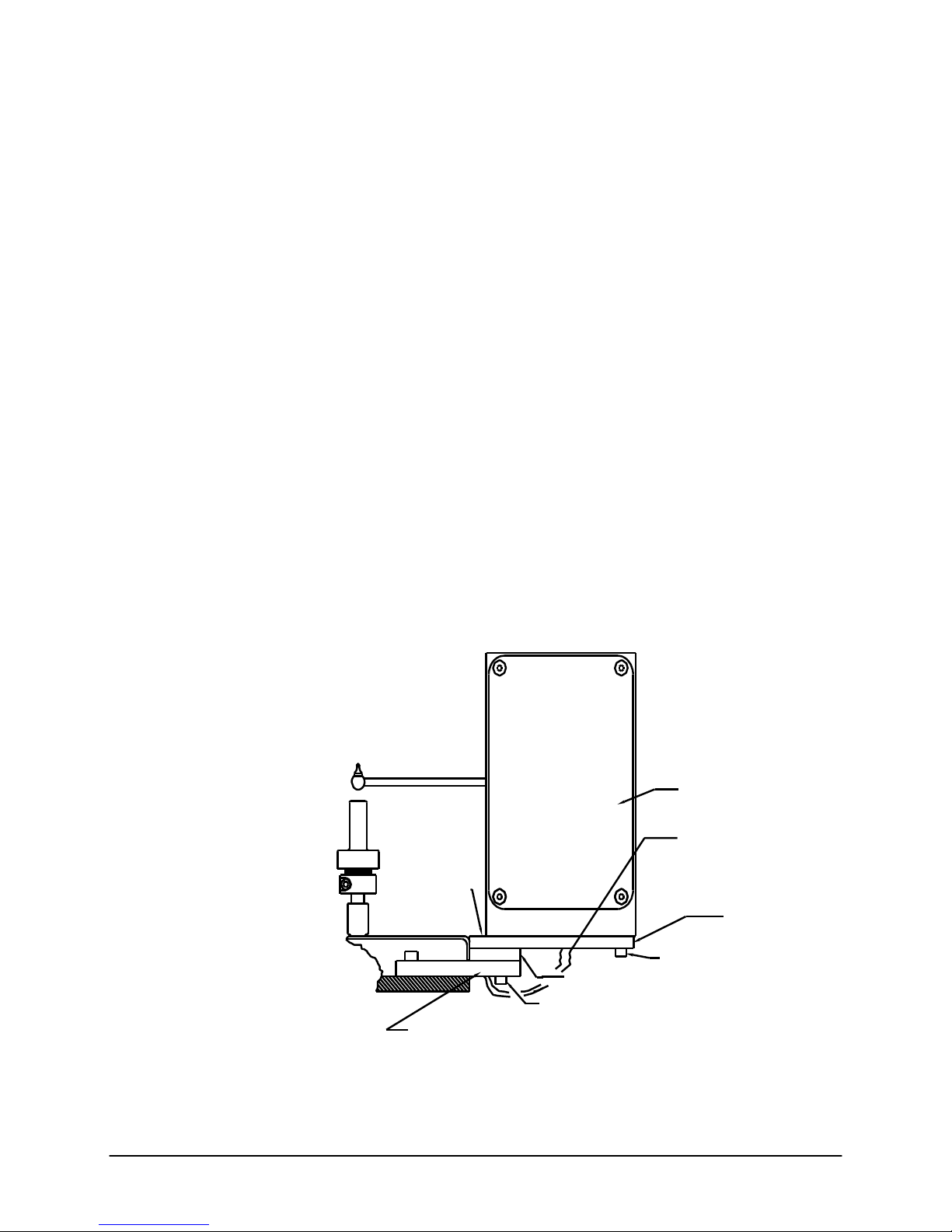
Digital Encoder Installation
Why use it?
Series 4000 Melt Indexer Operation Manual The Digital Encoder: Use and Calibration 51
No manual cuts
Check how homogeneous a sample is within a charge.
Get better precision (averages are less variable than a single observations)
See if barrel pressure drop is significant
Gain ability to reject data point if bubble or air pocket existed
The following parts should be in the encoder upgrade kit or included with the
encoder based melt indexer: (if ordered)
Two 1.25" long #8-32 Socket Head Cap Screws (SHCS)
Two 5/8" long #8-32 Socket Head Cap Screws
Two 5/8" long #8-32 Reduced Head Socket Cap Screws
Six #8 Lock Washers & Four #8 Washers
One Encoder Housing
One Long Plate, Plate #1
One Small Plate, Plate #2
Installation Steps (See Figure 1);
1. Using two 5/8 " Reduced Head Socket Cap Screws & two #8 Lock Washers,
attach plates #1 & #2 to plate #3 (plate #3 is already attached to the MI).
Tighten the screws.
Figure #1
Two Reduced Head
#8-32 x 5/8" Long
Socket Cap Screws &
Two Lock Washers
Plate #3 (Already Mounted to MI)
Encoder Housing
Phone Jack Cable
Two #8-32 x 5/8" SHCS
Plate #2
Two #8-32 x 1.25" SHCS
Two Washers & Lock Washers
Two Washers & Lock Wash
Plate #1
Page 60

2. Attach the Encoder Housing to the long plate (plate #1) using two 1.25" long
SHCS, two 5/8" long SHCS, 4 washers & 4 lock washers (washers first then
lock washers, i.e. lock washers under screw head).
Note for Pneumatic Lift Users: With the encoder arm in the down position,
lower the pneumatic lift. Move the arm up and down to check for clearance
with the pneumatic lift bucket. Clearance may be increased a small amount by
rotating the encoder housing before tightening the screws. If no clearance exists
and the arm hits the pneumatic lift bucket, contact Dynisco Polymer Test
Systems before proceeding.
Tighten the screws
3. Plug the phone jack cable into the encoder housing.
4. Move the encoder arm into the down position
5. Turn power on
6. Enable the Encoder by pressing the SETUP key. Browse the options until
you reach B FLAG and press EDIT. Press —› Quick Key so that ENCODR is
over the SELECT Quick Key. SELECT encoder and press ENTER to accept.
Press ESC. To back out to main menu.
7. Press the SYS key and select TEST. Browse the menu and select Digital
Encoder Test. The display shows current position and should change when the
arm is moved. Press QUIT to end procedure. ESC out to main menu.
8. See section entitled for detailed instructions on the variety of uses and
programming available with the encoder option.
Programming for use with the Digital
Enable the Digital Encoder
Method B: Setup
Auto Flag ON/OFF
Series 4000 Melt Indexer Operation Manual The Digital Encoder: Use and Calibration 52
This procedure assumes you are already set up to perform a Method B test as
explained in the section entitled “Method B Run”. Make sure Method B is
selected in the EDIT mode.
Press the SETUP key and browse the options until you reach B FLAG and
press EDIT. Press —› Quick Key so that ENCODR is over the SELECT Quick
Key. SELECT encoder and press ENTER to accept. Press ESC. twice to back
out to main menu. Enter the EDIT mode.
Press —› Quick Key until AUTO FLAG appears. Select ON to enable the
instrument to automatically determine one flag length based on real time flow
rates during the actual run. ASTM standard flag lengths will be used. No data
entry will be required. Auto flag is the easiest mode, it handles all the flag
details, unless you have a detailed test method use this option.
Select NO then you must enter more information in the options below about the
number of flags and their length. Press ENTER for next prompt.
Encoder
Page 61

Flag Calculation MANUAL or AUTO?
AUTO flag selected
So you picked MANUAL
Digital Flag Home
Testing and Maintenance
Series 4000 Melt Indexer Operation Manual The Digital Encoder: Use and Calibration 53
Select AUTO here unless you are an MFR wizard. This lets you pick flag
length which automatic adjusts the spacing between flags and start
positions. In MANUAL MODE the operator enters the start position of
each flag. The instrument will not perform any flag boundary or cross over
checking. Dynisco Polymer Test recommends a START position of 0.5
mm and a
STOP position not to exceed 30.0 mm. In AUTO MODE, the operator enters the
data collection START and STOP plunger positions (105 mm - 230 mm). The
instrument will then calculate all positions, flag lengths and flag separation
lengths (equal to 25% of the flag length). The instrument will perform flag
boundary crossover checking. Flag length will be decreased automatically until
all the requested numbers of flags fit between the START and STOP positions.
Minimum flag length is 1 mm.
Now that AUTO flag has been selected, enter the number of flags (Data points
collect for this loading of the barrel) and the flag length, press ENTER. Edit
the next parameter or quit edit mode and save program.
Enter the number of flags in the next prompt, 1 to 15, and press ENTER.
Select the length of the flags and press ENTER.
The next prompt will say “# ENCODER FLAGS NOT INITIALIZED”. This
means that you must enter start positions for each flag. Press EDIT an enter
start position for flag 1, press NEXT for flag 2 and so on. The instrument will
suggest positions for you, but you don’t have to accept them. EXIT when
finished editing. Dynisco Polymer Test recommends 1mm minimum flag
spaces.
Encoder Homing and Maintenance
Calibration: Digital Flag Home The Digital Encoder is calibrated at Dynisco
Polymer Test prior to shipment. Because the arm is locked into place,
calibration is rarely required.
The instrument does allow you to reset the home position of the encoder.
If calibration needs to be checked due to suspected encoder damage, then
contact Dynisco Polymer Test for assistance and the necessary tool kit.
Calibration Steps:
1. Press the SYS key and select CAL. Browse the menu and select
Digital Flag Home. The instrument prompts you to place the encoder
arm in the home position. This is the down most position that the flag
arm can go into.
2. Place the encoder arm in the down most position and press RESET
to set the encoder count to 105.00 mm at the top home position. Press
QUIT to end procedure. ESC out to main menu.
The encoder should now be set to the proper encoder settings. A digital
micrometer mounted in a special fixture is available from the factory to check
and verify accuracy of the encoder unit. Please contact your sales representative
and refer to part number 7051-59.
TEST: Digital Flag Position The instrument allows you to test the position of
the encoder arm. This procedure verifies the circuitry is working and can be
used to test calibration.
Test Steps:
Page 62

Complete Digital Encoder Calibration
Referenced Spec D1238-95
Series 4000 Melt Indexer Operation Manual The Digital Encoder: Use and Calibration 54
1. Press the SYS key and select TEST. Browse the menu and select
Digital Encoder Test.
2. The display shows current position and should change when the arm
is moved. Press QUIT to end procedure. ESC out to main menu.
Maintenance
1) Always place the arm into the lowered and locked position before
cleaning and at the end of the day. This prevents damage and ensures
that the encoder arm will be in the proper position upon power up.
2). If position gets “lost” during calibration procedure, at the start of the
test., go back and perform a “re-home”.
3) Never place any severe force against the side of the arm.
4) The real time flow during the test is an approximate value and should
not be used as an absolute value. Fractional flows below 1.0 MFI will
appear to change by larger steps due to resolution of sample time.
5) The encoder absolute resolution is .015 mm overall accuracy +/-
0.0254 mm.
6) Results on multiple flag runs are printed at the end of the test. This
differs from our standard Galaxy Series melt indexer.
The Digital Encoder is calibrated at Dynisco prior to shipment.
Because the arm is locked into place, calibration is rarely
required. If calibration needs to be checked due to suspected
encoder damage, then the following steps should be followed
if an Encoder Calibrator is available. If an encoder calibrator
is not available, and damage to the arm is suspected, then
contact Dynisco for assistance.
Tools Required:
Encoder Calibrator, Dynisco Part Number 7051-59, See Figure 3
Allen wrenches: 1/8", 9/64", 3/32", 5/64"
The calibration table (below) applies to ASTM D1238-95.
Changes made, if any, to ASTM 1238 after 95 are not reflected in
the table or drawings.
Calibration Steps:
1. Turn the instrument on and press <TEST> and answer
<Yes> to encoder test. The encoder position is now
displayed in millimeters.
2. Remove piston rod and rotate the stainless steel RTD
cover out of the way. Install Encoder Calibrator onto Melt
Indexer as shown in Figure 3. Turn the micrometer head
Page 63

on the calibrator counterclockwise until the MI displays a
negative value (example -1.0mm). Slowly turn the
micrometer head in the opposite direction while watching
the front display. Stop turning the micrometer head when
the MI display reads <+0.00>. Record the value of the
micrometer head position to the nearest 0.0000". Continue
rotating the micrometer head in the same direction until the
MI displays 25.40. Again read the micrometer head to the
nearest 0.0000".
Caution!: Once the first position is recorded, always turn
the micrometer head in the same direction (i.e. clockwise)
until the second measurement is recorded. Rotating the
micrometer head counterclockwise during a measurement
after passing through 0.00mm voids that test!
Note!: If the distance used during testing is exclusively
6.35mm, then the micrometer head may be rotated until the
MI displays 6.35mm. The difference in the micrometer
head readings should be 6.35 +/-0.03mm. If calibration is
required, then the method outlined in this procedure for
25.4mm should be followed.
3. Subtract the first micrometer head reading from the
second reading in step 2 and multiply the result by 25.4
(example 25.45). Go to Table 1 and determine if
calibration is required. The specified limits are +/-0.4%
ASTM D1238-95 and +/-0.10mm for DIN 53735. If
calibration is required, go to step 4, otherwise stop. Note!:
Repeating this measurement before proceeding with the
calibration procedure is recommended
4. If calibration is required, then the right hand cover on the
encoder housing must be removed. Remove the cover from
the Encoder Housing using a 3/32" Allen wrench.
Loosening the arm set screw shown in Figure 1 (5/64"
Allen Wrench). Be sure to loosen the proper set screw,
otherwise the entire arm will come loose from the shaft. If
the first set screw is accidentally loosened then the left
cover must also be removed and the first set screw
retightened when the arm is in the full down position when
the gear is oriented as shown in Figure 2. The second set
screw has been locked with removable Loctite and may
be stiff. After loosening the second arm set screw,
determine how far the adjustment screw on the arm (see
Figure 1) must be turned by using Table 1 & the results
from step 3. For example if the difference in the
micrometer head readings from step 3 yielded 25.45mm,
Series 4000 Melt Indexer Operation Manual The Digital Encoder: Use and Calibration 55
Page 64
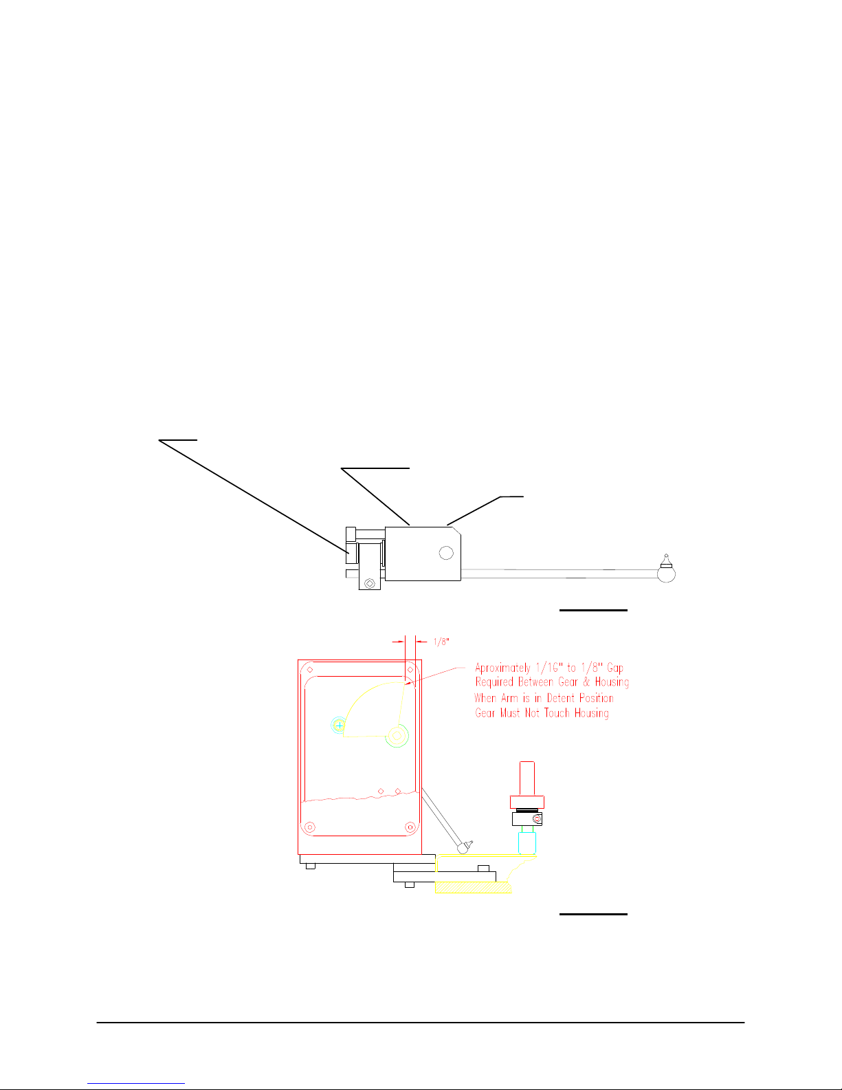
then the adjustment screw must be turned -87.6 degrees
(negative = ccw rotation as viewed from the rear of the
instrument) or about ccw 1/4 of a full turn to bring it back
into calibration per ASTM requirements. Use a 1/8" Allen
Wrench to turn the adjustment screw.
5. Recheck the encoder calibration by repeating the
micrometer measurements in steps 2 & 3. If further
adjustment is required then again use Table 1 to determine
the appropriate degrees of movement. Repeat this process
until the arm is calibrated. Once the arm is calibrated,
secure the arm in place by re tightening the second arm set
screw (see Figure 1). Apply removable thread locker
(Loctite type 290 or equivalent). Reinstall the cover and
tighten all hardware.
ADJUSTMENT SCREW: TURN CW TO EXTEND ARM
TURN CCW TO RETRACT ARM
Series 4000 Melt Indexer Operation Manual The Digital Encoder: Use and Calibration 56
SECOND SET SCREW LOCKS ARM IN PLACE
LOOSEN THIS SET SCREW TO CALIBRATE ENCODER
FIRST SET SCREW SECURES
ARM TO SHAFT
DO NOT LOOSEN THIS SET SCREW!
Figure 1
Figure 2
Page 65

TABLE 1
25.3:
ASTM &
DIN Min
25.5:
ASTM &
DIN Max
Series 4000 Melt Indexer Operation Manual The Digital Encoder: Use and Calibration 57
Micrometer
Reading When MI
Displays 25.4mm
dial
n
25.25
25.26
25.27
25.28
25.29
25.3
25.31
25.32
25.33
25.34
25.35
25.36
25.37
25.38
25.39
25.4
25.41
25.42
25.43
25.44
25.45
25.46
25.47
25.48
25.49
25.5
25.51
25.52
25.53
25.54
25.55
Number of Degrees
of Rotation Required
To Bring Arm Into
Calibration
degrees_turn
261
243
226
208
191
174
156
139
122
104
87
69
52
35
17
0
17
35
52
69
87
104
122
139
156
174
191
208
226
243
261
n
Positive turn = cw
screw rotation (push
arm out to make
longer)
Negative turn = ccw
screw rotation (pull
arm in to make
shorter)
Page 66
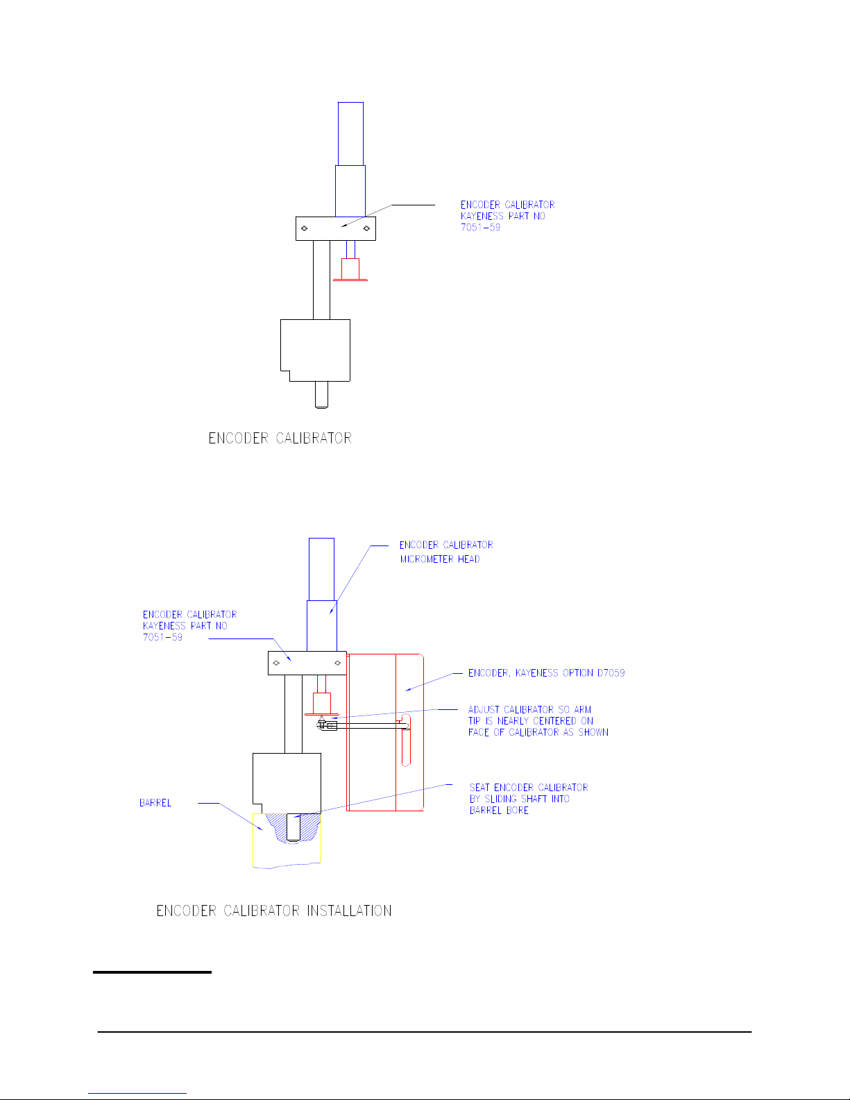
Figure 3
Series 4000 Melt Indexer Operation Manual The Digital Encoder: Use and Calibration 58
Page 67

Pneumatic Lift
Options
Activation and Operation
Activation and Operation
Series 4000 Melt Indexer Operation Manual Pneumatic Lift Options 59
Introduction
Introduction
Pneumatic Lift
The pneumatic lift accessory is a key piece of hardware to invest in if the flow
ratio test needs to be conducted. Also, if your material has a low flow rate and a
heavy weight is used, the pneumatic lift system lowers and raises the weight for
you.
Flow Ratio provides the user with insight into a materials shear thinning
ability and may correlate to molecular weight distribution. This test involves
obtaining flow rates at two different shear stresses, of generally a 10:1 ratio.
First, the lower mass weight is added to the piston. Next the higher mass weight
is added to the piston. The high mass weight may be well over 50 lbs. The
pneumatic lift automatically raises and lowers the weight safely.
You must enable the lift system in the SETUP mode, PNEU = ON. When
instrument is idle, the lift system is controlled by pressing the lift UP/ DOWN
arrows on the keypad.
There are also references to lift operation in the EDIT and SETUP modes.
Some notable settings are described:
Auto Purge = At end of test, last flag or cut, drop weight to purge material.
Auto Raise = If enabled, this option requests that the lift system raise the
weight after the experiment has ended
Auto Raise time = If Auto Raise enabled, wait this long to raise the weight. See
following graph
Mini-Lift
This is a small Pneumatic Lift assembly that supports the piston rod itself. It
is useful for high-flow materials and can be used in conjunction with a melt
plug.
You must enable the Mini Lift system in the SETUP mode, MINI LIFT = ON.
When instrument is idle, the lift system is controlled by pressing SHIFT then the
lift UP / DOWN arrows on the keypad.
There are references to Mini Lift operation in the EDIT and SETUP modes.
Some notable settings are described:
MINI Lift Hold = If enabled, this option requests that the lift system holds the
mini lift until the melt time has expired.
HOLD TIME = If MINI Lift Hold enabled, wait this long to lower the MINI
Lift after raise time. Intrinsic Viscosity Option
Page 68

Instrument Calibration
Calibration Steps:
SINGLE
Series 4000 Melt Indexer Operation Manual Instrument Calibration 60
RTD Electronics
The instrument must compensate for any offsets occurred in the internal
electronic circuitry. A known high precision resistor is inserted, through
software, into the RTD conversion electronic circuitry and a converted
temperature is displayed. If the temperature deviates from the expected value an
offset is computed. Accepting the offset applies it to all future temperature
conversions
The RTD electronics are calibrated at Dynisco Polymer Test prior to shipment
and really should not be changed.
RTD Sensor
Calibration of the RTD Sensors requires one or two thermometers or
equivalent.
The RTD sensor is calibrated at Dynisco Polymer Test prior to shipment.
There should be no need to re calibrate the RTD sensor. However, if there is a
need, please follow the following procedures.
NOTE: You must have one (SINGLE CAL) or two thermometers or
1. Press SYS Key and CAL Smart key to enter calibration mode. Select
RTD Sensor in the Calibrate Select mode.
2. The instrument prompts you to select a SINGLE or DOUBLE
procedure. Each procedure requires a thermometer, or two, rated at the
desired calibration temperature. SINGLE uses one temperature
reference to perform a calibration accurate to one temperature setting.
DOUBLE uses two temperature standards to create a linear curve
between the two temperatures. Temperatures falling between the two
standards will be accurate.
1. In the EDIT mode set the temperature on the instrument to the rated
temperature of your thermometer and wait for it to lock in. Enter the
SYS, CALIB mode and select RTD Sensor SINGLE. Insert the
thermometer into the thermometer well. Let the RTD and the
thermometer stabilize in the barrel for 15 minutes. Once the
temperature has stabilized, press STABLE to proceed.
2. Enter the thermometers temperature reading accurate to 1/10 degree
Celsius.
equivalent to perform this calibration.
Page 69

DOUBLE
Optical Flag
The instrument allows for the adjustment of the Optical Flag sensitivity. The
sensitivity determines how sensitive the Optical Flag LED Receiver is to being
in either two states, blocked or open. Sensitivity directly affects the measured
length of the tape flag.
The Optical sensor is calibrated at Dynisco Polymer Test prior to shipment.
There should be no need to re calibrate the RTD sensor. For this procedure you
must have the Flag Calibration Unit.
Calibration Steps:
3. The temperature offset is displayed. The offset is the difference
between the RTD temperature reading and the thermometer's
temperature reading. Select SAVE to use the new temperature offset or
manually enter an offset correction factor.
1. In the EDIT mode set the temperature on the instrument to the rated
temperature of your thermometer and wait for it to lock in. Enter the
SYS, CALIB mode and select RTD Sensor DOUBLE. Insert the first
thermometer into the thermometer well. Let the RTD and the first
thermometer stabilize in the barrel for 15 minutes. Once the
temperature has stabilized, press STABLE to proceed.
2. Enter the first thermometers temperature accurate to 1/10 degree
Celsius.
3. Set the temperature on the instrument to the rated temperature of the
second thermometer and wait for it to lock in. Insert the second
thermometer into the thermometer well. Let the RTD and the second
thermometer stabilized in the barrel for 15 minutes. Once the
temperature has stabilized, press STABLE to proceed.
4. Enter the second thermometers temperature accurate to 1/10 degree.
5. The temperature offset is displayed along with gain. The offset is the
difference between the stabilized temperature reading and the
thermometer's temperature readings. Select SAVE to use the new
temperature offset and gain values or manually enter an offset
correction factor and gain value.
1. Select Optical Flag in the Calibrate Select mode.
2. Make sure FLAG STATUS = OPEN when there is no flag blocking
Optical Sensor. Typical sensitivity readings are 50.
3. Place the electronic eye calibrator on top of the instrument and hang
a tape with a ¼" flag on its pin. The tape should hang such that it
extends down through the slot on the top right hand side of the
instrument.
3. Adjust the calibrator to lower the flag down until it just blocks the
optical sensor and the instrument display reads FLAG STATUS =
CLOSED. Set the calibrator dial to zero. Continue to lower the flag
until the flag leaves the sight line of the eye and the instrument display
reads FLAG STATUS = OPEN. Note the dial travel of the tape, it
should be within +/- 0.002 inches of 0.250 inches.
Series 4000 Melt Indexer Operation Manual Instrument Calibration 61
Page 70

4. If an adjustment is required, increase SENSITIVITY to lengthen the
flag reading or decrease SENSITIVITY to shorten flag length.
5. Press SAVE to permanently save the new value to memory.
Digital Encoder Calibration
The Digital Encoder is calibrated at Dynisco Polymer Test prior to shipment.
Because the arm is locked into place, calibration is rarely required.
The instrument does allow you to reset the home position of the encoder.
If calibration needs to be checked due to suspected encoder damage, then
Calibration: Digital Flag Home
Offset
Series 4000 Melt Indexer Operation Manual Instrument Calibration 62
contact Dynisco Polymer Test for assistance and the necessary tool kit.
Calibration Steps:
1. Press the SYS key and select CAL. Browse the menu and select Digital
Flag Home. The instrument prompts you to place the encoder arm in the home
position. This is the up most position that the flag arm can go into.
2. Place the encoder arm in the up most position and press RESET to
set the encoder count to 105.00 mm at the top home position. Press
QUIT to end procedure. ESC out to main menu.
The encoder should now be set to the proper encoder settings. A
digital micrometer mounted in a special fixture is available from the
factory to check and verify accuracy of the encoder unit. Please contact
your sales representative.
Intrinsic Viscosity
The IV offset is the difference between the computed IV and the
experimentally obtained IV. If option available, enter the difference here for
correlation during IV runs. Please reference previous IV sections in manual
Page 71

Instrument
Maintenance and
Troubleshooting
Monthly or Long Term
Daily
Weekly
Series 4000 Melt Indexer Operation Manual Instrument Maintenance and Troubleshooting 63
Maintenance
Remove the orifice and clean thoroughly with brush and drill bit. Clean your
indexer barrel with cotton patch when hot. Piston should spin easily when
placed into a clean barrel.
Give good cleaning with brass brush. Use oven cleaner to clean the piston rod
assembly and orifice.
Depending on your company policy, a calibration or calibration check may be
needed on a monthly, quarterly or yearly basis. It is a good idea to create a
repetitive maintenance schedule for your instrument. We cannot do this for you,
however we can suggest what to do:
Clean, Clean, Clean
Clean the dust and dirt out of the electronics module with clean air every six
months to one year, more often in dirty environments.
Remove the orifice and clean thoroughly.
Clean your barrel.
Use oven cleaner to clean the piston rod assembly and orifice.
Clean dust from optical flag sensor.
Check mechanical tolerances
Is your piston tip in spec? diameter = 0.3730 +/- .0003
length = 0.2500 +/- .0050
Does assembled piston rod weigh 100 grams?
Does your GO/NO GO gage work properly on the orifice?
Orifice length O.K.? length = 0.3150 +/- .0010
Operating temperature within spec? +/- 0.2 degree Celsius
Weights still weigh correctly?
Sample scale calibrated?
Digital Encoder calibration OK?
Page 72

Barrel Diameter
Support Vendors
The support vendor list shows the address for a bore gage manufacturer. Once
the barrel is extremely clean, all dimensional measurements are to be made at
room temperature it can be checked using a bore gage. Be sure to get or make a
long enough extension so the entire barrel can be checked. The barrels measure
0.3760 +/- .0002 leaving the factory.
Reference the section “Series 4000: A Guided Tour"; Selecting TEST in the
SYS Mode” to perform any hardware tests.
1. Pin Gages
Calibration or Certification of Cylindrical Pins
Zero Check
P.O. Box 903
Thomaston, Connecticut 06787
Tel: 203-283-5629
FAX: 203-283-4113
Meyer Gage Company
230 Burnham St.
South Windsor, CT 06074
(203) 528-6526
Ask for Class X pins (ISO specs are 0.0002 of nominal, ASTM specs
(D3835) are 0.0003 of nominal)
2. Cleaning Patches
Skyline Center Inc.
P.O. BOX 3064
Clinton, IA 52732
(319) 243-4065
(800) 747-4065 Extension-4065
FAX (319) 243-9901
3. Bore Gages
Inspex Corp.
664 Bussee Hwy.
Park Ridge, IL 60068
(708) 825-2200, Fax 825-0825
Order Diameter Probe #029 Probe, N-6 Needle, 0.0001 dial indicator,
8 mm holder, #029 ring (0.375"), 0.315" x 10" Depth Extension
4. NIST Standard Reference Materials (SRM)
For example: Standard Material 1476 is a branched polyethylene with
(a MFR of 1.19 0.01) as of 1992 cost about $255 for 50 grams.
SRM Catalog number is NIST Special Publication 260
To order: (301) 975-6776 Fax (301) 948-3730
5. Hg spill kits
Mercury Clean Up Spill Kits
Series 4000 Melt Indexer Operation Manual Instrument Maintenance and Troubleshooting 64
Page 73

Mercon Products: distributed by Fisher Scientific
Unit 8, 7551 Vantage Way
Delta, B.C.
Canada V4G 1C9
Tech Assistance (800)926-8999
(604) 940-0975 or call Fisher Scientific
PRINCO Instruments Inc. (Accepts Standards Hg for Recycle)
1020 Industrial Highway
Southampton, PA 18966
Conversion Factors
(215) 355-1500
Temperature
To Convert
From
To Use Formula
C K Tk = Tc +273.15
F C Tc = (Tf-32)/1.8
Viscosity
To Convert From ltiply By
Poise Pa-sec 0.10
centi-Poise Pa-sec 0.001
centi-Stokes m2/sec 1e-6
lb.-sec/ft2 Pa-sec 4.788026E+01
Pressure or Stress
To convert From Multiply By
Psi Pa 6.894757E+03
lb./in2 Pa 6.894757E+03
Atm (STD) Pa 1.01325E+05
Atm(1 kgf/cm2) Pa 9.80665E+4
bar Pa 1.0E+5
dyne/cm2 Pa 0.10
ksi (kip/in2) Pa 6.894757E+6
Troubleshooting
Flow Rates are Changing
Series 4000 Melt Indexer Operation Manual Instrument Maintenance and Troubleshooting 65
Cleanliness of the barrel and components is a critical factor in the behavior of
materials. The barrel of the unit should be cleaned as well as possible. All
components associated with the instrument (Piston tip and Orifice) should be
cleaned of all debris and material build-up. Remove the orifice to clean it. Next,
the units’ component tolerances and operational components should be checked:
The barrel temperature should be checked with the supplied
thermometer. (+/- 0.2° C)
The orifice should be checked for wear with the supplied GO-NO GO
gauge. (0.0825 +/-0.0002 in.)
Page 74

Temperature is Unstable
Mercury Separation in Thermometer
Reuniting Mercury Thermometers
Series 4000 Melt Indexer Operation Manual Instrument Maintenance and Troubleshooting 66
The piston tip should be checked for correct tolerances. (MI 0.3730
+/- 0.003 in.)
The guide bushing should be clean of material and easily slide up and
down the piston rod.
If running method B tests, are the factory supplied flags in good
condition.
The machine should be on a level surface. (Vertical alignment of the
bore)
The precision and accuracy of the test and instrument has been standardized by
ASTM D1238. Dynisco Polymer Test has found that the contributing factors to
the accuracy of the test includes sample weights (the amount of material tested),
timing (how long the material is in the heated barrel), packing technique,
dryness (has the material been properly dried), cleaning and cutting technique. It
is recommended to follow ASTM Specification D1238 for your material or
control sample. Also, pay attention to the recommendations of the manufacturer
or suppliers.
After a good cleaning and purge, your control sample should be run a
minimum of 5 times to verify that the problem is repeatable or even exists.
If you feel it is necessary to call the factory, please have your model number,
serial number and a complete program listing available (it may be helpful to fax
the program data) when you call.
Unplug the unit and remove the front cover. Verify all cables and circuit cards
are properly connected.
While the cover is off and the unit is unplugged, clean out all debris from the
unit’s internal components with compressed air. Clean all debris from the units
cooling fan. Air must flow freely to properly cool the unit.
Before using any thermometer it should be examined very carefully for
mercury separation in the main mercury co lumn, expansion chamber,
contraction chamber and bulb. Mercury separation in the bulb will usually
show as small bubbles. All the mercury must be united. If a thermometer does
not read zero at the ice point mercury separation is typically the cause.
There is no known method to completely insure that the mercury will
not separate in a thermometer when the thermometer is subjected to shock. This
can occur either in transit or by improper storage and handling. On the
following procedure describes a procedure for reuniting a separated mercury
column. Remember that the thermometer contains only two fluids, mercury and
gas. The object is to get all the liquid below the gas or conversely all the gas
above the liquid.
This method is the easiest to use and is the method PRINCO
recommends. In a small Dewar flask or thermos bottle mix powdered dr y ice
with Methanol or Acetone. Holding the thermometer vertical, immerse about
3/4 of the lower section of the bulb into the mixture. DO NOT immerse the
capillary or funnel section that is above the bulb into the mixture. The main
portion of the mercury will retreat into the bulb, and the separated portion will
follow.
Occasionally the separated portion may cling to the walls of the funnel
portion of the bulb. When all the mercury, including the separated portion, has
retreated into the bulb, remove the thermometer from the dry ice mixture. (See
Figure 1). The mercury should go together. Stand the thermometer in a vertical
Page 75
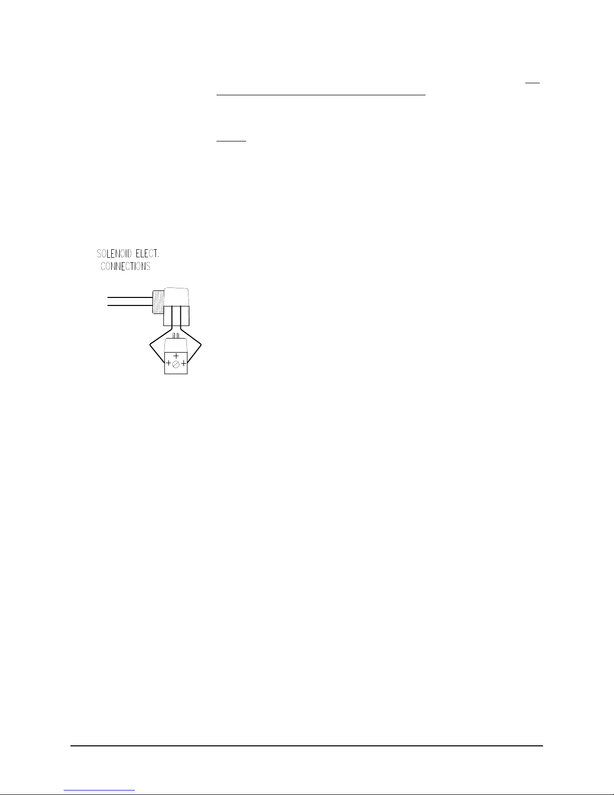
Pneumatic Lift Troubleshooting
WIRE TO
M I
P2-1 ,P2-3
position and allow the mercury to rise into the capillary of its own accord. DO
NOT TOUCH THE BULB WITH YOUR HANDS!
If you are unsuccessful repeat the cooling method except this time
gently tap (do not bounce) the thermometer bulb vertically on a desk pad after
removing from the flask.
NOTE: Where possible, thermometers should be stored in a vertical
position.
1.) The pneumatic lift system requires 60 to 80 psi for proper
operation. Please verify that your shop air meets these requirements.
2.) Clean out the in-line water filter.
3.) Verify that the unit is level and that the guide rod is not bent, see fig. C.
4.) Confirm that the hold valve switch is in the HOLD OFF position. See
figure A.
5.) If there is still no response please follow these procedures:
a.) Verify that the solenoid is getting the proper voltage. See fig. B.
Remove the solenoid electrical connector with a regular screwdriver.
Remove housing. Connect one lead of the DC voltmeter to chassis
ground and the other lead to either solenoid connectors. Enter the
solenoid cycle in the SYS, TEST mode. Measure the DC
voltage to each connection. Voltages should be a constant +4 to +5 volts or
greater on one connector and should switch from +4 to +5 volts (UP) to less
than +1 volt (DOWN) on the other connector. If these conditions are not met,
call Dynisco Polymer Test Systems tech support. If voltages are OK, proceed.
b.) Reassemble the solenoid and reenter the solenoid cycle. While the lift is
FIGURE B
Pneumatic Lift maintenance
Series 4000 Melt Indexer Operation Manual Instrument Maintenance and Troubleshooting 67
cycling, listen for the manifold to open and close; it's usually pretty noisy. If it
does not open and close, then listen if the solenoid clicks. If the Solenoid clicks
then the manifold is probably bad, if the solenoid does not click, then the
solenoid is probably bad. Call Dynisco Polymer Test tech support to order
replacement parts.
The guide rod and the pneumatic cylinder rod can be lubricated. Dynisco
Polymer Test suggests that WD-40 or machining oil be used as a lubricant. You
can also spray a small amount of WD-40 into the manifold to lubricate all
internal parts.
Page 76

FIGURE C
Series 4000 Melt Indexer Operation Manual Instrument Maintenance and Troubleshooting 68
GUIDE ROD
Page 77

Questions and
Answers
Typical Problems
Series 4000 Melt Indexer Operation Manual Questions and Answers 69
PROBLEM: Unit will not power up
SOLUTION: Check the fuse in the input power module, where the power cable
connects to the instrument. The fuse is rated at 5 Amperes 120 Volts. Verify the
supply voltage is correct (e.g. 110 VAC vs. 220 VAC). If you have any
difficulty, please call Dynisco Polymer Test Technical Support.
PROBLEM: The display works but the instruments keyboard does not respond.
SOLUTION: The keyboards internal ribbon cable has become detached due to
rough handling during shipment. Remove the top cover, swing open front
display/keyboard panel mount. Locate keyboard ribbon cable coming through
bottom center of the display/keyboard panel mount. Reconnect to the right side
connector (J2) on the mother board. If you have any difficulty, please call
Dynisco Polymer Test Technical Support.
PROBLEM: The digital temperature readout fluctuates, blinks or jumps
around:
SOLUTION: The temperature of the barrel cannot physically change
temperature as fast as 1 degree C per second. If it does, usually a bad electrical
connection or failing electrical component can be blamed. Make sure the die
and piston rod are in the unit when heating. If you have any difficulty, please
call Dynisco Polymer Test Technical Support.
PROBLEM: The VFD on the instrument displays a negative temperature.
SOLUTION: The RTD is in a shorting condition. Perform an RTD Display test.
If the reading is abnormal call Dynisco Polymer Test Technical Support.
PROBLEM: Temperature is stable but not reaching set point.
SOLUTION: Heat the instrument with the die and piston rod assembly in the
sample chamber. If you have any difficulty, please call Dynisco Polymer Test
Technical Support.
PROBLEM: The keyboard works but the instruments display does not work.
SOLUTION: The VFD's internal ribbon cable has become detached due to
rough handling during shipment. Remove the top cover, swing open front
display/keyboard panel mount. Locate VFD ribbon cable. Reconnect to the left
side connector (J1) on the mother board. Check connection to the VFD itself. If
you have any difficulty, please call Dynisco Polymer Test Technical Support.
Page 78

PROBLEM: How do I check the temperature?
SOLUTION: Enter a temperature value in the edit mode, preferable one that
matches your thermometer. Make sure the orifice and piston rod are in the
barrel. Allow the instrument to lock into temperature and equilibrate for 15
minutes. Remove the thermometer chimney set screw located on the top of the
barrel. Insert thermometer and let stabilize for 10 min.. If display does not agree
with thermometer perform temperature calibration.
PROBLEM: My digital Encoder is not responding! What’s going on?
SOLUTION: Make sure the encoder is enabled in the SETUP mode. Verify all
cables are plugged in at base of Encoder housing and inside the Indexer.
PROBLEM: My method B numbers are wrong, even after inputting my
manufacturer’s values for apparent melt density! Why?
SOLUTION: The value reported by the manufacturer is probably a solid state
density, not the melt density. Run an A/B method experiment to acquire the
proper melt density.
PROBLEM: My MFI is changing!
SOLUTION: Your MFI may vary as much as 2% due to operator
inconsistencies, even the smallest things may affect MFI. The most common
cause is not keeping the barrel and orifice properly cleaned. We recommend the
power cleaning kit (PN 8052-97K) to help guarantee and promote a clean
system. Also, make sure sample weight is consistent throughout tests.
PROBLEM: What flag do I use?
SOLUTION: Please refer to the section "Choosing a Timing Flag" in the
manual.
PROBLEM: How long should my cut time be for a Method A run?
SOLUTION: Dynisco Polymer Test suggests that you collect about 1 gram of
sample extrudate, or more, before making your 2nd cut.
PROBLEM: My printer does not work! What gives?
SOLUTION: Enable the printer in the SETUP mode. Make sure it's an on-
line PROBLEM: My materials Melt Flow Rate is much higher than normal?
SOLUTION: If the material is moisture sensitive, dry it. Moisture can make
Flow Rates increase greatly, especially on Polyesters (PET, PBT), Nylons,
Polysulfones and material with filler content (glass, calcium carbonate, and
talc).
Typical Questions
Series 4000 Melt Indexer Operation Manual Questions and Answers 70
QUESTION: How often should I test my material?
ANSWER: This depends on how much material your plant receives and the
method that it is received, a suggested guideline follows:
- Material supplied by tankers (3 tests)
- Material supplied in bags on pallets (3 tests per pallet, check lot numbers)
- Material supplied in individual bags (3 tests per bag)
Also conduct a test if there is a production problem
QUESTION: My material has a Certificate of Conformity and my results don’t
agree.
Page 79

ANSWER: A Certificate of Conformity is based on only one test, usually. As a
polymer may vary throughout the process, you cannot be sure that the polymer
is the same throughout your delivery. It has been known for processors to have
problems during production and for them to think that they are machine
problems, when in fact it is their material that is out of specification.
QUESTION: How long should a test take from start to finish?
ANSWER: This depends, to a large extent, on the MFI of the material, but
roughly the times are as follows:
- Loading/Weighing sample (2 minutes)
- Melting time (6 minutes)
- Testing time MFI > 8 (1-2 minutes)
- Testing time MFI 3 - 8 (3-6 minutes)
- Testing time MFI < 3 (6-10 minutes)
- Cleanup (2 minutes)
- Heat Stabilization (2 minutes)
QUESTION: What form should my sample be in?
ANSWER: For ease of loading, granules are best. Regrinds, plastic films,
powders and liquids have all been successfully tested. Watch for air entrapment
with some forms.
QUESTION: What type of sample preparation should I perform?
ANSWER: Some type of drying conditions may need to be carried out before
testing. Preferably, this should be done at the same conditions your production
material goes through. LDPE, HDPE and PP therefore will not need any
significant drying.
QUESTION: Should I check the MFI on my finished product?
ANSWER: Sure! You want to know if what you made yesterday is the same as
what you made today. If it’s the proper quality and did it change? You also want
to make sure that the performance of your process and end product are
consistent day to day.
QUESTION: What are the lowest MFI and highest MFI we can test?
ANSWER: Typically down to 0.1 gm/ 10 mins. Any values lower increase your
weight or temperature.
Typically the highest would be 500 gm/ 10 mins. however it is possible to go
up to 1500 gm/ 10 mins. Tests above 50 gm/ 10 mins. are uncommon and do
require skilled operators.
QUESTION: How long does the die last?
ANSWER: The die is made of tungsten carbide which is extremely wear
resistant. The die should last for several years if cleaned and maintained
properly. Some manufacturers use stainless steel dies which last 2 years.
QUESTION: What should the barrel be cleaned with?
ANSWER: With the tools and cotton patches provided. There should be no oils
on the patches. You can heat the machine to its highest temperature to burn off
any residue. You really shouldn’t use any solvents to clean the barrel due to fire
and health hazards. Check with your company safety manager what the policy
is.
QUESTION: Can we leave the machine on 24 hours a day?
Series 4000 Melt Indexer Operation Manual Questions and Answers 71
Page 80

ANSWER: Yes, in fact many of our instruments have been on for several years.
Some customers use a timer to turn their instrument on before they arrive for
work, and off after they have left.
Sometimes lightning storms can damage the instrument. As with all
accessories that are plugged into wall outlets, a surge protector is a great idea.
QUESTION: What spare parts should I keep?
ANSWER: This depends on how mission critical your operation is. You should
have spare fuses and maybe a piston tip and die. A spare parts list should be
Series 4000 Melt Indexer Operation Manual Questions and Answers 72
supplied with the quote.
Page 81

Digital Flag, Digital
Encoder
Firmware
Flow rate
Flow Rate Ratio
Intrinsic Viscosity
Melt Flow Indexer
Method A
Method A/B
Method B
MVI
Optical Flag or
Optical Eye Sensor
Pneumatic Lift
RTD
Timing Flag
Series 4000 Melt Indexer Operation Manual Glossary of Terms 73
Glossary of Terms
A device used to measure piston travel
Software embedded into the instrument's hardware. Sometimes you may receive
firmware upgrades
A measure of polymer's mass flow rate (grams extruded in 10 minutes) using a
particular orifice under specified conditions of temperature and load
A test used to obtain two different flow rates at two different shear stresses. This
may provide insight to the slope of a flow curve.
A measure of the capacity of a polymer molecule to enhance viscosity.
An instrument used to perform ASTM D-1238 testing of molten plastics and
other polymers
Measurement of the amount of extrudate accumulated for a given amount of
time. The test is completely manual and is sometimes called the "cut-n-weigh"
method
This test measures the amount of material extruded over time and a volume
extruded over a distance. A means of measuring travel is employed. In order to
run a method B test, an A/B run MUST be run first to determine the polymer's
melt density.
Measurement of the volume of material that extrudes over time. Can be
conducted only after an A/B experiment is conducted. This is a "no-cuts,"
automated test that is the most convenient for busy laboratories.
Material is forced through an orifice at a specific temperature using a specific
weight. The volume extruded in a 10minute period is an MVI, in cm/10 min.
A component used to measure the amount of time it takes the piston rod to
travel a certain distance.
An optional system allowing the user to automatically raise and lower weights
onto the piston rod. Requires 70psi shop air.
(Resistance Temperature Detector) A component that senses temperature and
changes in temperature.
A device that the optical eye uses to measure distance and time
Page 82

USB Setup
PC and Daisy Instructions
LMI’s with USB ports will need the COM Port that is automatically assigned by a PC,
when an USB device is plugged in to it, set to match a COM Port in the Daisy
configuration file. This can be done through the PC as follows:
Daisy Software Start-Up
Verify USB port assigned to LMI:
1) Power-up LMI with USB connected to PC
2) On PC, go to Control Panel/System/Hardware/Device Manager/Ports(Com
and LPT)
3) Note Comm port of “ATEN USB to Serial Bridge”
4) Go to PC and open (with WordPad or NotePad) C:\ “Device1.cfg”
Series 4000 Melt Indexer Operation Manual USB Setup 74
Page 83

5) Scroll down to line, “RS232=’X’, 19200,N,8,1” and if necessary, change
parameter ‘X’ to match the USB port assignment noted from Device
Manager in step 3.
6) Save Device1.CFG if COM Port was changed.
To Verify Communications:
7) Start LMI software by opening “Daisy for Melt Indexer” from desktop or
through C:\Program Files\
Username: alpha
Password: alpha
Series 4000 Melt Indexer Operation Manual USB Setup 75
Page 84

8) Either of the two windows below may open. If this first window does not
open, go to “Daisy 8.50 Eclipse” window (the second below) and press
upper, left button. If the first window fails to open, check communications to
instrument.
Series 4000 Melt Indexer Operation Manual USB Setup 76
Page 85

PC and MI Works Instructions
LMI’s with USB ports will need the COM Port that is automatically assigned by a PC,
when an USB device is plugged in to it, set to match a COM Port choice within MI Works.
This can be done through the PC as follows:
Verify USB port assigned to LMI
1) Power-up LMI and PC with USB connected from LMI to PC
2) On PC, go to Control Panel/System/Hardware/Device Manager/Ports(Com
and LPT)
3) Note COM port of “ATEN USB to Serial Bridge”
4) If it COM1 or COM2, then skip ahead to the MI Works communications
settings in step 8. If it is not COM1 or COM2, then you will need to change it
to either COM1 or COM2 but COM2 would be preferred. COM2 most likely
will not conflict with a hardware, 9-Pin, serial port on the PC. If the “ATEN
USB to Serial Bridge” does not show in the "Ports" section or has errors, a
driver may need to be installed. The driver for the PC’s operating system
can be found at:
http://www.aten.com/products/productItem.php?pcid=20050107104554001&psid=20050117102915002&pid=2005
022316346005
At this webpage, select “Resources” and then “Software & Driver” to
download. Install driver and then repeat from step 1.
Series 4000 Melt Indexer Operation Manual USB Setup 77
Page 86

5) Right click on “ATEN USB to Serial Bridge” and select Properties.
6) Select “Port Settings”
Series 4000 Melt Indexer Operation Manual USB Setup 78
Page 87

7) Select “Advanced”. In “Advanced Settings”, select “COM2” (or COM1), then
“OK” to “Advanced Settings, then “OK” to “Communications Port Properties”.
Then, close Device Manager.
8) Start MI Works and the following window should appear:
Series 4000 Melt Indexer Operation Manual USB Setup 79
Page 88

9) Select “Communications” and the following window should appear. Select
the COM port that was assigned the USB port in step 7 in the “Select PC
Port” section of the window. MI Works should now function with the LMI.
Series 4000 Melt Indexer Operation Manual USB Setup 80
Page 89

Index
I.V. 41
L
Level the Melt Indexer 6
Loading the Barrel 23, 29, 36
LOCKOUT 18
I
A
action list 48
An Overview of MI 3
AVERAGE 17
Bench Requirements and Placement 6
B
Calculations \: Method A/B 27
Calculations \: Method B 32
Calculations\: Method A 21
Charge Weight 44
Check List 48
Cleaning Up 25, 37
Cleaning Up a really Big Mess 26
Computer connection 9
consistent mass 3
Conversion Factors 65
C
D
default password 18
die 25
Electrical Hazard 10
E
Flag 35
Flow Rate Ratio 39
FORM FEED 18
Fumes from Materials 11
F
Series 4000 Melt Indexer Operation Manual Index 81
gloves 9
User preferences 17
G
MACHINE ID 18
Maintenance 63
Making the Cut 24, 31
melt density 32
Mercury 10
mercury thermometers 10
Method B Encoder Option 4, 50
Method B Flags Setup 33
Model Descriptions 2
moisture 3
Multi Weight 40
Multiple Method A 51
on 21
out-of-control 48
Oven cleaner 26
Pa-sec 65
Poise 65
Power Cord 9
PRINTER 18
Prtinter Connection 9
PVC 11
REJECTION 17
RTD Connection 9
RUN PARAMETERS 18
SETUP 17
Standard Operating Procedure 46
Support Vendors 64
Timing Flag 35
Typographic Conventions 1
Unpacking the Indexer 6
M
O
P
R
S
T
U
Page 90

Series 4000 Melt Indexer Operation Manual Page 82
 Loading...