

Page 1

OPERATING MANUAL
240 and 290 Series240 and 290 Series
240 and 290 Series240 and 290 Series
240 and 290 Series
MM
MM
M
eltelt
eltelt
elt
Pr Pr
Pr Pr
Pr
ee
ee
e
ss
ss
s
ss
ss
s
urur
urur
ur
e e
e e
e
TT
TT
T
rr
rr
r
anan
anan
an
smittsmitt
smittsmitt
smitt
erer
erer
er
ss
ss
s
Intrinsically safe and explosion proofIntrinsically safe and explosion proof
Intrinsically safe and explosion proofIntrinsically safe and explosion proof
Intrinsically safe and explosion proof
pressure transmitters with integratedpressure transmitters with integrated
pressure transmitters with integratedpressure transmitters with integrated
pressure transmitters with integrated
amplifier for use in hazardous environmentsamplifier for use in hazardous environments
amplifier for use in hazardous environmentsamplifier for use in hazardous environments
amplifier for use in hazardous environments
P/N 974080
05/05 Rev. F
ECO # 29918
II 1G II 1G
II 1G II 1G
II 1G
AA
AA
A
TEXTEX
TEXTEX
TEX
100a 100a
100a 100a
100a
Page 2
OPERATING MANUAL
TT
TT
T
ABLEABLE
ABLEABLE
ABLE
OFOF
OFOF
OF
C C
C C
C
ONTENTSONTENTS
ONTENTSONTENTS
ONTENTS
ContentContent
ContentContent
Content
PP
PP
P
agag
agag
ag
ee
ee
e
IconIcon
IconIcon
Icon
1. General 3
2. Notes on safety 5
3. Technical data 7
4. Function 22
5. Transport/delivery 23
6. Assembly 24
7. Commissioning 35
8. Maintenance 39
9. Accessories 42
10. Troubleshooting 43
11. CE-Declaration of conformity 44
12. Ex-Declaration of conformity 45
Page 3

3
GENERAL
1.1.
1.1.
1.
GG
GG
G
ENERALENERAL
ENERALENERAL
ENERAL
1.1 Important information .......................................................................................................... 3
1.2 Copyright ............................................................................................................................. 3
1.3 Explanation of icons ............................................................................................................ 4
1.4 Abbreviations ...................................................................................................................... 4
1.5 Correct use .......................................................................................................................... 4
1.6 User’s obligations ................................................................................................................ 4
1.11.1
1.11.1
1.1
II
II
I
MPORMPOR
MPORMPOR
MPOR
TT
TT
T
ANTANT
ANTANT
ANT
INFORMAINFORMA
INFORMAINFORMA
INFORMA
TIONTION
TIONTION
TION
This manual applies to the 240 and 290 series only. It must be kept near the equipment in a readily
and immediately accessible location at all times.
The content of this manual must be read, understood and followed in its entirety. This applies in
particular to the notes on safety. Following the safety instructions will help to prevent accidents, defects
and malfunctions.
DD
DD
D
YNISCYNISC
YNISCYNISC
YNISC
OO
OO
O will not be held liable for any injury, loss or damage resulting from failure to follow the
instructions in this manual.
If the product malfunctions, in spite of having followed the operating instructions, please contact the
DD
DD
D
YNISCYNISC
YNISCYNISC
YNISC
OO
OO
O customer service department (see the back of the manual for contact information).
1.21.2
1.21.2
1.2
CC
CC
C
OPYRIGHTOPYRIGHT
OPYRIGHTOPYRIGHT
OPYRIGHT
Copyright law requires that this manual be used for in-house purposes only.
All reproduction, even partially and for in-house purposes, requires the approval of
DD
DD
D
YNISCYNISC
YNISCYNISC
YNISC
OO
OO
O. This
manual may not be forwarded to third parties.
Page 4
4
GENERAL
1.1.
1.1.
1.
33
33
3
EE
EE
E
XPLANAXPLANA
XPLANAXPLANA
XPLANA
TIONTION
TIONTION
TION
OFOF
OFOF
OF
ICIC
ICIC
IC
ONSONS
ONSONS
ONS
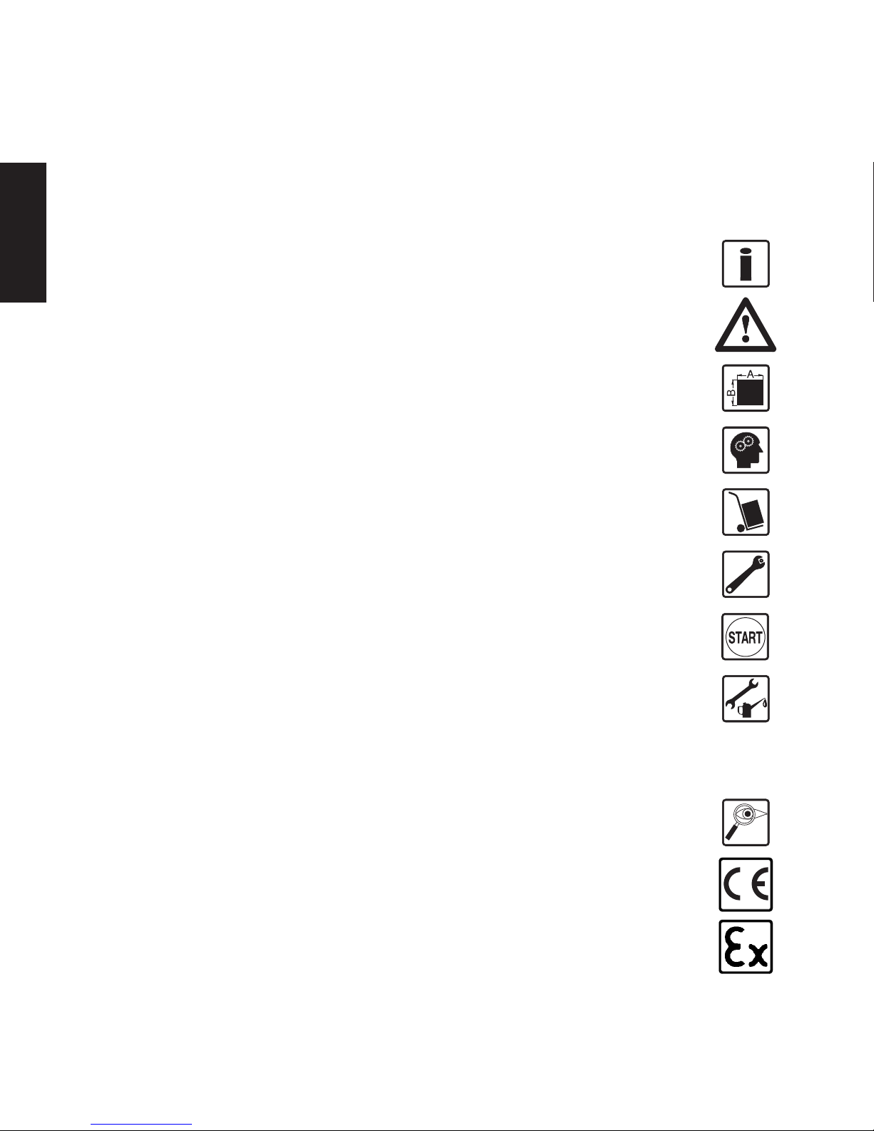
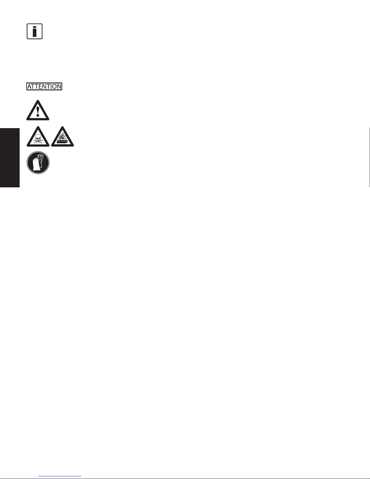
The manual uses icons to indicate information pertaining to safety:
Risk of destruction or damage to equipment, machines or installations
General danger to life or limb
Specific danger to life or limb
You MUST do this
The safety instructions are provided again in the individual chapters of the manual.
1.41.4
1.41.4
1.4
AA
AA
A
BBREVIABBREVIA
BBREVIABBREVIA
BBREVIA
TIONSTIONS
TIONSTIONS
TIONS
The following abbreviations are used:
OMOM
OMOM
O M Operating manual
f.s.f.s.
f.s.f.s.
f.s. of full scale
PTPT
PTPT
P T pressure transmitter
1.51.5
1.51.5
1.5
CC
CC
C
ORRECTORRECT
ORRECTORRECT
ORRECT
USEUSE
USEUSE
USE
The 240 and 290 series of pressure transmitters is specially designed for measuring pressure in explosive
atmospheres (safety class, EEx ia IIC T4, Ta=-20°C to +80°C) as part of a larger overall system. It
contains an integrated signal amplifier. The 240 and 290 series of pressure transmitters can be used in
media temperatures up to 400°C. If the pressure transmitter is used in other applications, the safety and
accident prevention regulations specific to that application must be followed.
When using the PT as a safety component in accordance with the EC Machine Directive,When using the PT as a safety component in accordance with the EC Machine Directive,
When using the PT as a safety component in accordance with the EC Machine Directive,When using the PT as a safety component in accordance with the EC Machine Directive,
When using the PT as a safety component in accordance with the EC Machine Directive,
Annex IIc, the equipment manufacturer must take any necessary precautions to ensure thatAnnex IIc, the equipment manufacturer must take any necessary precautions to ensure that
Annex IIc, the equipment manufacturer must take any necessary precautions to ensure thatAnnex IIc, the equipment manufacturer must take any necessary precautions to ensure that
Annex IIc, the equipment manufacturer must take any necessary precautions to ensure that
mm
mm
m
alfalf
alfalf
alf
uu
uu
u
nctionnction
nctionnction
nction
ss
ss
s
of of
of of
of
the P the P
the P the P
the P
TT
TT
T
cc
cc
c
annotannot
annotannot
annot
c c
c c
c
auau
auau
au
se dse d
se dse d
se d
amam
amam
am
agag
agag
ag
e or injure or injur
e or injure or injur
e or injur
yy
yy
y
..
..
.
The 240 and 290 series of pressure transmitters are also designed for explosion proof areas approved
by factory mutual for Class I, Division 1, Groups A, B, C & D. Explosion proof models are also
approved for intrinsic safety by factory mutual for Class I, Division 1, Groups A, B, C, & D.
1.61.6
1.61.6
1.6
UU
UU
U
SS
SS
S
ERER
ERER
ER
’’
’’
’
SS
SS
S
OBLIGAOBLIGA
OBLIGAOBLIGA
OBLIGA
TIONSTIONS
TIONSTIONS
TIONS
The operator or owner of the larger overall system, e.g. a machine, is responsible for following the
safety and accident prevention regulations that apply to the specific application.
Page 5

5
SAFETY
2.2.
2.2.
2.
NN
NN
N
OTESOTES
OTESOTES
OTES
ONON
ONON
ON
SAFETYSAFETY
SAFETYSAFETY
SAFETY
The operator or owner of the larger overall system is responsible for following the safety
and accident prevention regulations that apply to the specific application.
TT
TT
T
oo
oo
o
xx
xx
x
icic
icic
ic
h h
h h
h
azaz
azaz
az
arar
arar
ar
d!d!
d!d!
d!
The PT contains a small amount of mercury (Hg) as its transmission medium. If the
diaphragm is damaged, mercury may escape.
Never transport or store the PT without the protective cap. Remove the cap shortly
before installation.
IfIf
IfIf
If
mer mer
mer mer
mer
cc
cc
c
urur
urur
ur
yy
yy
y
i i
i i
i
ss
ss
s
inh inh
inh inh
inh
alal
alal
al
ed or swed or sw
ed or swed or sw
ed or sw
alal
alal
al
lolo
lolo
lo
ww
ww
w
ed, seeked, seek
ed, seeked, seek
ed, seek
medic medic
medic medic
medic
alal
alal
al
att att
att att
att
ention immediention immedi
ention immediention immedi
ention immedi
atat
atat
at
ely!ely!
ely!ely!
ely!
Mercury is hazardous waste and must be disposed of in accordance with applicable
laws.
DD
DD
D
YNISCYNISC
YNISCYNISC
YNISC
OO
OO
O will accept defective PTs.
If mercury escapes, use airtight packaging!
When planning machinery and using the PT, follow the safety and accident prevention
regulations that apply to your application, e.g.:
• EN 60204, Electrical equipment in machines.
• EN 292, Machine safety, general design guidelines.
• DIN 57 100 Part 410, Protection against electric shock.
• EN 50 014:1997, General Requirements
• EN 50 020:1994, Intrinsically safe apparatus
• EN50284:1999, Special requirements fro Group II Category 1G
Mounting and electrical connection of the PT must be done by specialists with EMC training,
following all applicable regulations, and in
pressureless, voltage-free, intrinsically safepressureless, voltage-free, intrinsically safe
pressureless, voltage-free, intrinsically safepressureless, voltage-free, intrinsically safe
pressureless, voltage-free, intrinsically safe
condition with the
machine switched offmachine switched off
machine switched offmachine switched off
machine switched off.
The mThe m
The mThe m
The m
acac
acac
ac
hine muhine mu
hine muhine mu
hine mu
ss
ss
s
tt
tt
t
be sec be sec
be sec be sec
be sec
urur
urur
ur
ed aged ag
ed aged ag
ed ag
ainain
ainain
ain
ss
ss
s
tt
tt
t
bein bein
bein bein
bein
g swg sw
g swg sw
g sw
itit
itit
it
cc
cc
c
hed bhed b
hed bhed b
hed b
acac
acac
ac
kk
kk
k
on! on!
on! on!
on!
Ambient temperature for the electronics housing
mm
mm
m
ax. +80°Cax. +80°C
ax. +80°Cax. +80°C
ax. +80°C (safety class T4 max.).
Higher temperatures can result in damage and malfunction. Do not install the pressure
transmitter in places where this temperature is exceeded.
ExpExp
ExpExp
Exp
lolo
lolo
lo
ss
ss
s
ion hion h
ion hion h
ion h
azaz
azaz
az
arar
arar
ar
d!d!
d!d!
d!
Deviation of the supply voltage from the value given in the technical specifications, or
false polarity, can damage the pressure transmitter and cause malfunctions that can
pose a risk of explosion.
Page 6

6
SAFETY
Operate only with an intrinsically safe, EMC compliant power supply with the following
specifications when employing the pressure 4-20mA output:
Supply voltage max.40 V DC
Current output max. 100 mA
Inductivity max. 0
Capacity max. 0.017 µF
For PT’s that are explosion proof Class I, Division 1, Groups A, B, C & D, the power
supply rating is 16-40 Vdc.
Do not lay connecting cables in the direct vicinity of cables carrying higher voltage or
used to switch inductive or capacitive loads.
Page 7

7
TECHNICAL DATA
3.3.
3.3.
3.
TT
TT
T
EE
EE
E
CHNICALCHNICAL
CHNICALCHNICAL
CHNICAL
D D
D D
D
AA
AA
A
TT
TT
T
AA
AA
A
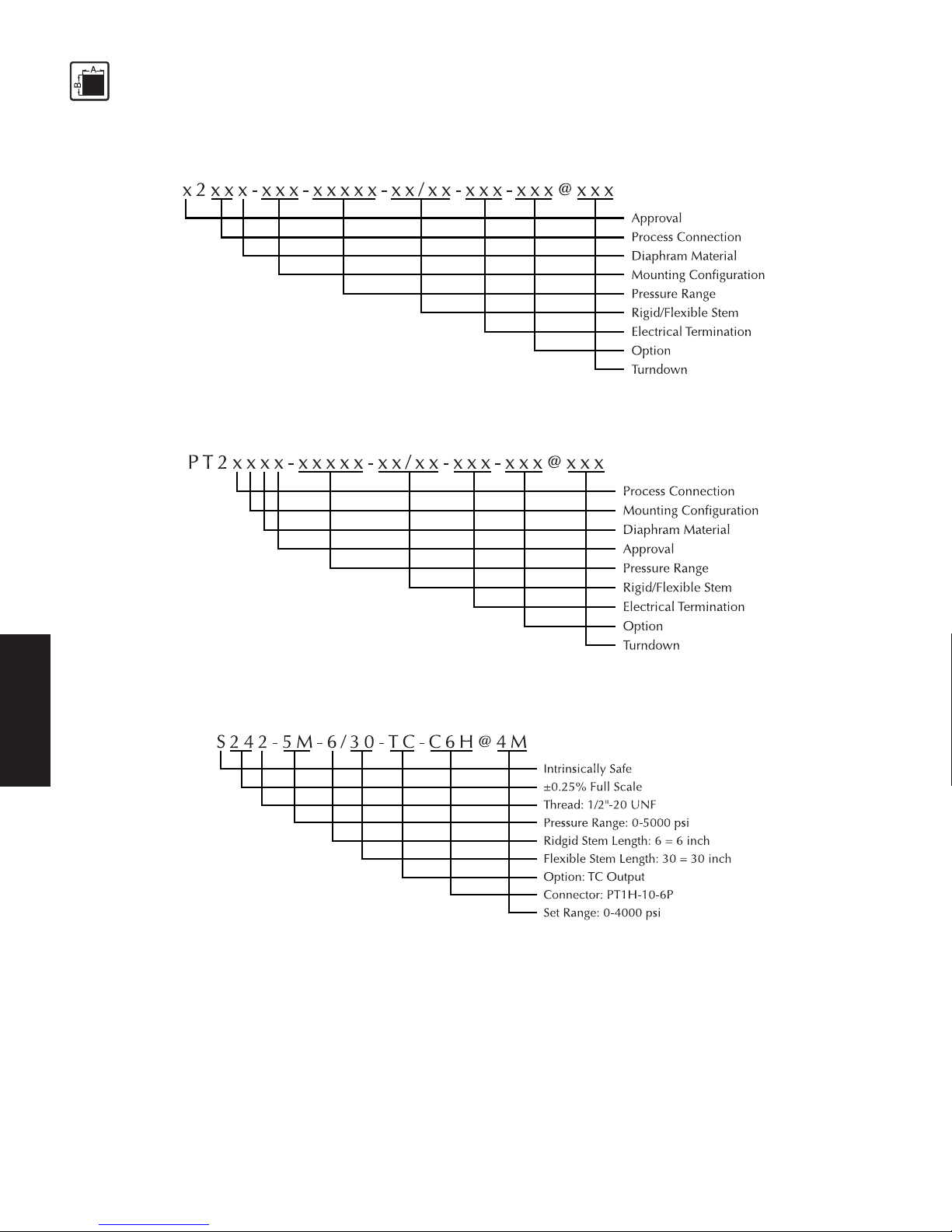
3.1 Ordering guides ................................................................................................................... 7
3.1.1 Ordering guide for x242 and x243 ....................................................................................... 8
3.1.2 Ordering guide for PT241x, PT244x, PT290x, PT291x, and PT292x ..................................... 8
3.2 Ordering example ............................................................................................................... 8
3.3 Safety related specifications ................................................................................................8
3.4 Performance characteristics ................................................................................................. 9
3.4.1 Accuracy ............................................................................................................................. 9
3.4.2 Resolution .......................................................................................................................... 10
3.4.3 Repeatabilty ...................................................................................................................... 10
3.5 Pressure side connection .................................................................................................... 10
3.6 Pressure ranges .................................................................................................................. 10
3.6.1 Pressure ranges in bar ........................................................................................................ 10
3.6.2 Max. Overload .................................................................................................................. 1 1
3.6.3 Burst pressure ..................................................................................................................... 1 1
3.6.4 Natural frequency .............................................................................................................. 1 1
3.7 Rigid stem/flexible stem .................................................................................................... 11
3.7.1 x242x, x243x ..................................................................................................................... 1 1
3.7.2 PT241xx............................................................................................................................. 12
3.7.3 PT244xx ............................................................................................................................. 1 2
3.7.4 PT290x, PT291x, PT292x ................................................................................................... 1 2
3.8 Electrical Data .................................................................................................................. 1 2
3.9 Temperature influence ....................................................................................................... 12
3.10 EMC requirements ............................................................................................................. 1 3
3.11 Materials ........................................................................................................................... 13
3.12 Mounting torque ................................................................................................................ 13
3.13 Environmental Protection .................................................................................................. 1 4
3.14 Weight............................................................................................................................... 14
3.15 Dimensions ........................................................................................................................ 14
3.13.1
3.13.1
3.1
OO
OO
O
RDERINGRDERING
RDERINGRDERING
RDERING
GUIDESGUIDES
GUIDESGUIDES
GUIDES
The exact meanings of the letter/digit combinations are given in the corresponding sections of
chapter 3.
Page 8
8
TECHNICAL DATA
3.1.13.1.1
3.1.13.1.1
3.1.1
OO
OO
O
RDERINGRDERING
RDERINGRDERING
RDERING
GUIDEGUIDE
GUIDEGUIDE
GUIDE
FORFOR
FORFOR
FOR
XX
XX
X
22
22
2
42 42
42 42
42
ANDAND
ANDAND
AND
XX
XX
X
22
22
2
44
44
4
33
33
3
3.1.23.1.2
3.1.23.1.2
3.1.2
OO
OO
O
RDERINGRDERING
RDERINGRDERING
RDERING
GUIDEGUIDE
GUIDEGUIDE
GUIDE
FORFOR
FORFOR
FOR
PT241 PT241
PT241 PT241
PT241
XX
XX
X
, PT244, PT244
, PT244, PT244
, PT244
XX
XX
X
, PT290, PT290
, PT290, PT290
, PT290
XX
XX
X
, PT291, PT291
, PT291, PT291
, PT291
XX
XX
X
, ,
, ,
,
ANDAND
ANDAND
AND
PT292 PT292
PT292 PT292
PT292
XX
XX
X
3.23.2
3.23.2
3.2
OO
OO
O
RDERINGRDERING
RDERINGRDERING
RDERING
E E
E E
E
XAMPLEXAMPLE
XAMPLEXAMPLE
XAMPLE
3.33.3
3.33.3
3.3
SS
SS
S
AFETAFET
AFETAFET
AFET
YY
YY
Y
RELARELA
RELARELA
RELA
TEDTED
TEDTED
TED
SS
SS
S
PEPE
PEPE
PE
CIFICACIFICA
CIFICACIFICA
CIFICA
TIONSTIONS
TIONSTIONS
TIONS
ATEX certificate No.: SIRA 03ATEX2422
EX-Safety class EEx ia IIC T4 (Ta = -20°C to +80°C)
FM approvals Class I, Division 1 Groups A, B, C & D
CC
CC
C
erer
erer
er
tified mtified m
tified mtified m
tified m
axax
axax
ax
imum imum
imum imum
imum
vv
vv
v
aluealue
aluealue
alue
ss
ss
s
f f
f f
f
or EExor EEx
or EExor EEx
or EEx
i i
i i
i
a IICa IIC
a IICa IIC
a IIC
T4T4
T4T4
T4
Page 9

9
TECHNICAL DATA
Associated electrical equipment must satisfy the following conditions:
Supply voltage max. 40 V DC
Current output max. 100 mA
Inductivity max. 0
Capacity max. 0.017 µF
3.43.4
3.43.4
3.4
PP
PP
P
ERFORMANCERFORMANC
ERFORMANCERFORMANC
ERFORMANC
EE
EE
E
CHARACHARA
CHARACHARA
CHARA
CTERISCTERIS
CTERISCTERIS
CTERIS
TICTIC
TICTIC
TIC
SS
SS
S
x2xxx - xxx - xxxxx - xx / xx - xxx - xxx@xxx
3.4.13.4.1
3.4.13.4.1
3.4.1
AA
AA
A
CC
CC
C
CC
CC
C
URAURA
URAURA
URA
CYCY
CYCY
CY
(Linearity, hysterisis and repeatability)
3.4.13.4.1
3.4.13.4.1
3.4.1
AA
AA
A
XX
XX
X
242, 242,
242, 242,
242,
XX
XX
X
243243
243243
243
±0.25% of full scale
(0-1500 psi and above)
±0.50% of full scale
(0-1000 psi and below)
3.4.13.4.1
3.4.13.4.1
3.4.1
BB
BB
B
PT241PT241
PT241PT241
PT241
XX
XX
X
±0.50% of full scale
(0-1500 psi and above)
±1.0 of full scale
(10-1000 psi and below)
3.4.13.4.1
3.4.13.4.1
3.4.1
CC
CC
C
PT244PT244
PT244PT244
PT244
XX
XX
X
±0.25% of full scale
(0-500 psi and above)
±0.50% of full scale
(0-250 psi)
3.4.13.4.1
3.4.13.4.1
3.4.1
DD
DD
D
PT290PT290
PT290PT290
PT290
XX
XX
X
, PT291, PT291
, PT291, PT291
, PT291
XX
XX
X
, PT292, PT292
, PT292, PT292
, PT292
XX
XX
X
±0.50% of full scale
Page 10

10
TECHNICAL DATA
3.4.23.4.2
3.4.23.4.2
3.4.2
RR
RR
R
ESOLUTIONESOLUTION
ESOLUTIONESOLUTION
ESOLUTION
Infinite
3.4.33.4.3
3.4.33.4.3
3.4.3
RR
RR
R
EPEAEPEA
EPEAEPEA
EPEA
TT
TT
T
ABILITABILIT
ABILITABILIT
ABILIT
YY
YY
Y
±0.10% of full scale
3.53.5
3.53.5
3.5
PP
PP
P
RESSURERESSURE
RESSURERESSURE
RESSURE
SIDESIDE
SIDESIDE
SIDE
CONNECTIONCONNECTION
CONNECTIONCONNECTION
CONNECTION
2 = 1/2" 20 UNF 2A (x24
22
22
2x . . . )
1, 3, 4, 90, 91 or 92 = flange (PT24
11
11
1xx-x), (x24
33
33
3x-x), (PT24
44
44
4xx-x), (PT2
9090
9090
90xx-x), (PT2
9191
9191
91xx-x), or
(PT2
9292
9292
92xx-x)
3.63.6
3.63.6
3.6
PP
PP
P
RESSURERESSURE
RESSURERESSURE
RESSURE
RANGESRANGES
RANGESRANGES
RANGES
3.6.13.6.1
3.6.13.6.1
3.6.1
PP
PP
P
RESSURERESSURE
RESSURERESSURE
RESSURE
RANGESRANGES
RANGESRANGES
RANGES
ININ
ININ
IN
PSIPSI
PSIPSI
PSI
3.6.13.6.1
3.6.13.6.1
3.6.1
AA
AA
A
Model numberModel number
Model numberModel number
Model number
PP
PP
P
ermittermitt
ermittermitt
ermitt
ed pred pr
ed pred pr
ed pr
ee
ee
e
ss
ss
s
ss
ss
s
urur
urur
ur
e re r
e re r
e r
anan
anan
an
gg
gg
g
e in Pe in P
e in Pe in P
e in P
SISI
SISI
SI
x24xx-2.5C-x/xx 0-250
x24xx-5C-x/xx 0-500
x24xx-7.5C-x/xx 0-750
x24xx-1M-x/xx 0-1,000
x24xx-1.5M-x/xx 0-1,500
x24xx-3M-x/xx 0-3,000
x24xx-5M-x/xx 0-5,000
x24xx-7.5M-x/xx 0-7,500
x24xx-10M-x/xx 0-10,000
x24xx-15M-x/xx 0-15,000
x24xx-20M-x/xx 0-20,000
x24xx-30M-x/xx 0-30,000
3.6.13.6.1
3.6.13.6.1
3.6.1
BB
BB
B
Model numberModel number
Model numberModel number
Model number
PP
PP
P
ermittermitt
ermittermitt
ermitt
ed pred pr
ed pred pr
ed pr
ee
ee
e
ss
ss
s
ss
ss
s
urur
urur
ur
e re r
e re r
e r
anan
anan
an
gg
gg
g
e in Pe in P
e in Pe in P
e in P
SISI
SISI
SI
PT24xx-2.5C-x/xx 0-250
PT24xx-5C-x/xx 0-500
PT24xx-7.5C-x/xx 0-750
PT24xx-1M-x/xx 0-1,000
PT24xx-1.5M-x/xx 0-1,500
PT24xx-3M-x/xx 0-3,000
Page 11

11
TECHNICAL DATA
PT24xx-5M-x/xx 0-5,000
PT24xx-7.5M-x/xx 0-7,500
3.6.13.6.1
3.6.13.6.1
3.6.1
CC
CC
C
Model numberModel number
Model numberModel number
Model number
PP
PP
P
ermittermitt
ermittermitt
ermitt
ed pred pr
ed pred pr
ed pr
ee
ee
e
ss
ss
s
ss
ss
s
urur
urur
ur
e re r
e re r
e r
anan
anan
an
gg
gg
g
e in Pe in P
e in Pe in P
e in P
SISI
SISI
SI
PT29xx-25-x/xx 0-25
PT29xx-50-x/xx 0-50
PT29xx-1C-x/xx 0-100
PT29xx-2.5C-x/xx 0-250
PT29xx-5C-x/xx 0-500
PT29xx-7.5C-x/xx 0-750
PT29xx-1M-x/xx 0-1,000
PT29xx-1.5M-x/xx 0-1,500
PT29xx-3M-x/xx 0-3,000
PT29xx-5M-x/xx 0-5,000
PT29xx-7.5M-x/xx 0-7,500
PT29xx-10M-x/xx 0-10,000
3.6.23.6.2
3.6.23.6.2
3.6.2
MM
MM
M
AXAX
AXAX
AX
. O. O
. O. O
. O
VERLVERL
VERLVERL
VERL
OO
OO
O
ADAD
ADAD
AD
( (
( (
(
WITHOUTWITHOUT
WITHOUTWITHOUT
WITHOUT
INFLINFL
INFLINFL
INFL
UENCINGUENCING
UENCINGUENCING
UENCING
OPERAOPERA
OPERAOPERA
OPERA
TINGTING
TINGTING
TING
DD
DD
D
AA
AA
A
TT
TT
T
AA
AA
A
))
))
)
x24xx 2 x full scale pressure or 35,000 psi, whichever is less.
PT29x 2 x full scale pressure or 15,000 psi, whichever is less.
PT24x 2 x full scale pressure
3.6.33.6.3
3.6.33.6.3
3.6.3
BB
BB
B
URSTURST
URSTURST
URST
PRESSUREPRESSURE
PRESSUREPRESSURE
PRESSURE
6 x nominal value, max. 45,000 psi
3.6.43.6.4
3.6.43.6.4
3.6.4
NN
NN
N
AA
AA
A
TURALTURAL
TURALTURAL
TURAL
FREFRE
FREFRE
FRE
QUENCYQUENCY
QUENCYQUENCY
QUENCY
50 Hz [-3db]
3.73.7
3.73.7
3.7
RR
RR
R
IGIDIGID
IGIDIGID
IGID
STEMSTEM
STEMSTEM
STEM
//
//
/
FLEXIBLEFLEXIBLE
FLEXIBLEFLEXIBLE
FLEXIBLE
STEMSTEM
STEMSTEM
STEM
3.7.13.7.1
3.7.13.7.1
3.7.1
XX
XX
X
242242
242242
242
XX
XX
X
, ,
, ,
,
XX
XX
X
243243
243243
243
XX
XX
X
6 = 152 mm standard length for rigid version
6/18 = 152 mm stem length / 457 mm flexible stem
Other lengths available
Page 12

12
TECHNICAL DATA
3.3.
3.3.
3.
77
77
7
.2.2
.2.2
.2
PT241PT241
PT241PT241
PT241
XXXX
XXXX
XX
2.031/18 = 2.031” stem length / 18” flexible stem
3.7.33.7.3
3.7.33.7.3
3.7.3
PT244PT244
PT244PT244
PT244
XXXX
XXXX
XX
2.406/18 - 2.406” stem length / 18” flexible stem
Other lengths available
3.7.43.7.4
3.7.43.7.4
3.7.4
PT290PT290
PT290PT290
PT290
XX
XX
X
, PT291, PT291
, PT291, PT291
, PT291
XX
XX
X
, PT292, PT292
, PT292, PT292
, PT292
XX
XX
X
5/30 = 5” stem length / 30” flexible stem
Other lengths available
3.83.8
3.83.8
3.8
EE
EE
E
LELE
LELE
LE
CTRICALCTRICAL
CTRICALCTRICAL
CTRICAL
DD
DD
D
AA
AA
A
TT
TT
T
AA
AA
A
Configuration 4-arm Wheatstone bridge strain gauge with int. amplifier
Output signal 2-wire 4 - 20 mA
Supply voltage 16-40 VDC for EEx ia IIC T4 and FM approved explosion proof models
Power consumption ≤20 mA
Zero balance (x24x and PT24x)
adjusment range -40% to +10% > 500 psi
-80% to +20% < 500 psi
(PT29x)
-40% to +10% > 100 psi
-80% to +20% < 100 psi
3.93.9
3.93.9
3.9
TT
TT
T
EMPERAEMPERA
EMPERAEMPERA
EMPERA
TURETURE
TURETURE
TURE
INFLINFL
INFLINFL
INFL
UENCUENC
UENCUENC
UENC
EE
EE
E
Electronics housingElectronics housing
Electronics housingElectronics housing
Electronics housing
Max. housing temperatures
Safety class T4 -20°C to +80°C
Compenstated -18°C to +65°C
temperature range
240 Series
Page 13

13
TECHNICAL DATA
Compenstated -18°C to +60°C
temperature range
PT29x Series
Zero shift due to temperature change on electronics housing
x24x, PT24x, PT29x 0.01% full scale/°F maximum (0.02% f.s./°C maximum)
Diaphragm (in contact with media)Diaphragm (in contact with media)
Diaphragm (in contact with media)Diaphragm (in contact with media)
Diaphragm (in contact with media)
Maximum temperature at the diaphragm
x2xxxx 400°C (750°F)
Zero shift due to temperature change on the diaphragm
x2xxxx 15 psi/100°F typical (27 psi/100°C)
PT29x, PT24x 1 psi/100°F typical (from 75°F to 450°F)
2 psi/100°F typical (from 450°F to 600°F)
0.07 bar/38°C typical (from 24°C to 232°C)
0.14 bar/38°C typical (from 233°C to 315°C)
3.103.10
3.103.10
3.10
EMC EMC
EMC EMC
EMC
REQUIREMENTSREQUIREMENTS
REQUIREMENTSREQUIREMENTS
REQUIREMENTS
Conforming to CE in accordance with EMC directive.
Electromagnetic Interference DIN EN 550223 1995
Immunity DIN EN 61000-4-2 1995
Radiated, Radio Freq, etc. DIN EN 61000-4-3 1995 +A1:1998+A2:2000
Pulse Magnetic Field DIN EN 61000-4-9 1993 + A1:2001
Surge Immunity DIN EN 61000-4-5 1995 + A1:2000
Conducted Disturbences DIN EN 61000-4-6 1996 + A1:2000
Power Frequency Magnetic Field DIN EN 61000-4-8 1993 + A1:2001
3.113.11
3.113.11
3.11
MM
MM
M
AA
AA
A
TERIALSTERIALS
TERIALSTERIALS
TERIALS
Diaphragm 15-5PH Mat. No. 1.4545 DyMax™ coated
Stem 17-4PH Mat. No. 517400
3.123.12
3.123.12
3.12
TT
TT
T
ORQUEORQUE
ORQUEORQUE
ORQUE
x242x x243x PT292 PT24x, PT290 and PT291
max. 56.5 Nm max. 5.6 Nm max. 14.1 Nm max. 14.1 Nm
(500 inch-lbs.) (50 inch-lbs.) (125 inch-lbs.) (125 inch-lbs.)
min. 11.3 Nm min. 4.5 Nm min. 11.3 Nm min. 11.3 Nm
(100 inch-lbs.) (40 inch-lbs.) (100 inch-lbs.) (100 inch-lbs.)
Page 14

14
TECHNICAL DATA
3.133.13
3.133.13
3.13
EE
EE
E
NVIRONMENTNVIRONMENT
NVIRONMENTNVIRONMENT
NVIRONMENT
ALAL
ALAL
AL
PROPRO
PROPRO
PRO
TETE
TETE
TE
CTIONCTION
CTIONCTION
CTION
TT
TT
T
OO
OO
O
IE IE
IE IE
IE
CC
CC
C
5 5
5 5
5
22
22
2
99
99
9
PT housing with conduit 1P66 nema 4x
PT02A-10-6P 1P55 nema 4x (Using Dynisco P/N 711600)
PT02H-10-6P 1P66 nema 4x (Using Dynisco P/N 711610)
PT1H-10-6P 1P66 nema 4x (Using Dynisco P/N 711610)
3.143.14
3.143.14
3.14
WW
WW
W
EIGHTEIGHT
EIGHTEIGHT
EIGHT
1-5 lbs.
3.153.15
3.153.15
3.15
DD
DD
D
IMENSIONSIMENSIONS
IMENSIONSIMENSIONS
IMENSIONS
Page 15
15
TECHNICAL DATA
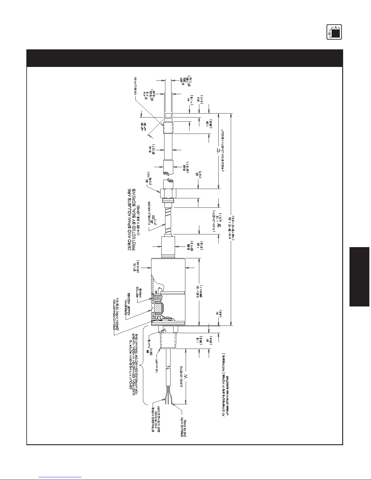
Fig. 3-1Fig. 3-1
Fig. 3-1Fig. 3-1
Fig. 3-1
x242 Modelsx242 Models
x242 Modelsx242 Models
x242 Models
Page 16

16
TECHNICAL DATA
Fig. 3-2Fig. 3-2
Fig. 3-2Fig. 3-2
Fig. 3-2
x243 Modelsx243 Models
x243 Modelsx243 Models
x243 Models
Page 17

17
TECHNICAL DATA
Fig. 3-3Fig. 3-3
Fig. 3-3Fig. 3-3
Fig. 3-3
PT241 ModelsPT241 Models
PT241 ModelsPT241 Models
PT241 Models
Page 18

18
TECHNICAL DATA
Fig. 3-4Fig. 3-4
Fig. 3-4Fig. 3-4
Fig. 3-4
PT244x ModelsPT244x Models
PT244x ModelsPT244x Models
PT244x Models
Page 19

19
TECHNICAL DATA
Fig. 3-5Fig. 3-5
Fig. 3-5Fig. 3-5
Fig. 3-5
PT290 ModelsPT290 Models
PT290 ModelsPT290 Models
PT290 Models
Page 20

20
TECHNICAL DATA
Fig. 3-6Fig. 3-6
Fig. 3-6Fig. 3-6
Fig. 3-6
PT291x ModelsPT291x Models
PT291x ModelsPT291x Models
PT291x Models
Page 21

21
TECHNICAL DATA
Fig. 3-7Fig. 3-7
Fig. 3-7Fig. 3-7
Fig. 3-7
PT292x ModelsPT292x Models
PT292x ModelsPT292x Models
PT292x Models
Page 22

22
FUNCTION
4.4.
4.4.
4.
FF
FF
F
UNCTIONUNCTION
UNCTIONUNCTION
UNCTION
4.1 Construction ...................................................................................................................... 22
4.2 Description of Functions .................................................................................................... 22
4.14.1
4.14.1
4.1
CC
CC
C
ONSTRUCTIONONSTRUCTION
ONSTRUCTIONONSTRUCTION
ONSTRUCTION
The PTs of series 240’s and 290’s are industry standard.
The main advantages are:
• Intrinsically safe EEx ia IIC T4
• thermal stability
• resistance to aggressive media
• insensitivity to electromagnetic radiation (EMC)
• liquid-filled transmission system (mercury)
• pressure measurements in plastic melt up to a temperature of 400°C
4.24.2
4.24.2
4.2
DD
DD
D
ESCRIPTIONESCRIPTION
ESCRIPTIONESCRIPTION
ESCRIPTION
OFOF
OFOF
OF
F F
F F
F
UNCTIONSUNCTIONS
UNCTIONSUNCTIONS
UNCTIONS
Through a closed, liquid-filled pressure transmission system, the PT furnishes an electrical signal
that is proportional to the pressure of the melt.
The pressure applied by the medium is forwarded to the measuring diaphragm and the mercury in
the capillary. The deflection of the measuring diaphragm changes the resistance of the strain gauge
bonded to the measuring diaphragm. The strain gauge is a Wheatstone bridge.
Depending on the model, the integrated amplifier generates and electrical signal (mA or Volts)
proportional to the pressure.
Fig. 4-1Fig. 4-1
Fig. 4-1Fig. 4-1
Fig. 4-1
Functioning Principle of the PT of the X242 SeriesFunctioning Principle of the PT of the X242 Series
Functioning Principle of the PT of the X242 SeriesFunctioning Principle of the PT of the X242 Series
Functioning Principle of the PT of the X242 Series
Page 23

23
TRANSPORT
5.5.
5.5.
5.
TT
TT
T
RANSRANS
RANSRANS
RANS
PORPOR
PORPOR
POR
TT
TT
T
/ D / D
/ D / D
/ D
ELIVERYELIVERY
ELIVERYELIVERY
ELIVERY
5.1 Transport / packing / transport damage .............................................................................. 23
5.2 Storage .............................................................................................................................. 23
5.3 Scope of delivery .............................................................................................................. 23
TT
TT
T
oo
oo
o
xx
xx
x
icic
icic
ic
h h
h h
h
azaz
azaz
az
arar
arar
ar
d!d!
d!d!
d!
The PT contains a small amount of mercury (Hg) as its transmission medium. If the
diaphragm is damaged, mercury may escape.
Never transport or store the PT without the protective shell bolted in place. Remove the
shell shortly before installation.
IfIf
IfIf
If
mer mer
mer mer
mer
cc
cc
c
urur
urur
ur
yy
yy
y
i i
i i
i
ss
ss
s
inh inh
inh inh
inh
alal
alal
al
ed or swed or sw
ed or swed or sw
ed or sw
alal
alal
al
lolo
lolo
lo
ww
ww
w
ed, seeked, seek
ed, seeked, seek
ed, seek
medic medic
medic medic
medic
alal
alal
al
att att
att att
att
ention immediention immedi
ention immediention immedi
ention immedi
atat
atat
at
elyely
elyely
ely
..
..
.
Mercury is hazardous waste and must be disposed of in accordance with applicable
laws.
DD
DD
D
YNISCYNISC
YNISCYNISC
YNISC
OO
OO
O will accept defective PTs.
If mercury escapes, use airtight packaging!
ESD sensitive component. Electrostatic discharge may damage the PT. Take ESD
precautions.
5.15.1
5.15.1
5.1
TT
TT
T
RANSRANS
RANSRANS
RANS
PORPOR
PORPOR
POR
TT
TT
T
//
//
/
PP
PP
P
AA
AA
A
CKINGCKING
CKINGCKING
CKING
//
//
/
TRANSTRANS
TRANSTRANS
TRANS
PORPOR
PORPOR
POR
TT
TT
T
DD
DD
D
AMAGEAMAGE
AMAGEAMAGE
AMAGE
• Do not let the PT be damaged by other items during transit.
• Use only the original packaging.
• Report transport damage to
DD
DD
D
YNISCYNISC
YNISCYNISC
YNISC
OO
OO
O immediately in writing.
5.25.2
5.25.2
5.2
SS
SS
S
TT
TT
T
ORAGEORAGE
ORAGEORAGE
ORAGE
• Store the PT in original packaging only.
• Protect against dust and moisture.
5.35.3
5.35.3
5.3
SS
SS
S
CC
CC
C
OPEOPE
OPEOPE
OPE
OFOF
OFOF
OF
DELIVERYDELIVERY
DELIVERYDELIVERY
DELIVERY
• PT with diaphragm protection cap
• Fastening clip (transmitter with flexible stem only)
• Calibration sheet
• Operating manual with declaration of conformity
Page 24

24
ASSEMBLY
6.6.
6.6.
6.
AA
AA
A
SS
SS
S
SS
SS
S
EMBLEMBL
EMBLEMBL
EMBL
YY
YY
Y
6.1 Mounting hole ................................................................................................................... 24
6.2 Checking the mounting hole ............................................................................................. 27
6.3 Mounting the Pressure Transmitter ..................................................................................... 28
6.4 Mounting PTs with flexible stem ....................................................................................... 29
6.5 Mounting PTs with flange .................................................................................................. 30
6.6 Electrical connection ........................................................................................................ 30
6.6.1 EMC / CE compliant connection ...................................................................................... 3 1
6.7 Connection assignments .................................................................................................... 3 1
6.8 Flange configurations ........................................................................................................31
Ambient temperature for the electronics housing max. +80°C (safety class T4 max.).
Higher temperatures can result in damage and malfunction.
Do not install the pressure transmitter in places where this temperature is exceeded.
6.16.1
6.16.1
6.1
MM
MM
M
OUNTINGOUNTING
OUNTINGOUNTING
OUNTING
H H
H H
H
OLEOLE
OLEOLE
OLE
To produce the mounting hole, use only
DD
DD
D
YNISCYNISC
YNISCYNISC
YNISC
OO
OO
O machining tool kit (DYNISCO P/N
200925).
• Drill the mounting hole as shown in fig. 6-1, 6-2, 6-3, 6-4, 6-5, 6-6.
Fig. 6-1Fig. 6-1
Fig. 6-1Fig. 6-1
Fig. 6-1
Mounting Hole x242Mounting Hole x242
Mounting Hole x242Mounting Hole x242
Mounting Hole x242
Page 25

25
ASSEMBLY
Fig. 6-2Fig. 6-2
Fig. 6-2Fig. 6-2
Fig. 6-2
Mounting hole x243Mounting hole x243
Mounting hole x243Mounting hole x243
Mounting hole x243
Fig. 6-3Fig. 6-3
Fig. 6-3Fig. 6-3
Fig. 6-3
Mounting hole PT241xMounting hole PT241x
Mounting hole PT241xMounting hole PT241x
Mounting hole PT241x
Page 26

26
ASSEMBLY
Fig. 6-4Fig. 6-4
Fig. 6-4Fig. 6-4
Fig. 6-4
Mounting hole PT244xMounting hole PT244x
Mounting hole PT244xMounting hole PT244x
Mounting hole PT244x
Fig. 6-5Fig. 6-5
Fig. 6-5Fig. 6-5
Fig. 6-5
Mounting hole PT290 & PT291Mounting hole PT290 & PT291
Mounting hole PT290 & PT291Mounting hole PT290 & PT291
Mounting hole PT290 & PT291
Page 27

27
ASSEMBLY
Fig. 6-6Fig. 6-6
Fig. 6-6Fig. 6-6
Fig. 6-6
Mounting hole PT292Mounting hole PT292
Mounting hole PT292Mounting hole PT292
Mounting hole PT292
When reworking the mounting hole, pay particular attention to the centricity of:
• the hole,
• the thread, if present, and
• the sealing surface.
Pressure sealing takes place on the 45° beveled sealing surface and on the front cylindrical section
of the PT (see figures 6-1, 6-2, 6-3, 6-4, 6-5, 6-6).
The sealing surface must be:
• correctly machined
• free from marks and rough edges
• free from solidified plastic residue.
6.26.2
6.26.2
6.2
CC
CC
C
HEHE
HEHE
HE
CKINGCKING
CKINGCKING
CKING
THETHE
THETHE
THE
MOUNTINGMOUNTING
MOUNTINGMOUNTING
MOUNTING
HOLEHOLE
HOLEHOLE
HOLE
((
((
(
NONO
NONO
NO
TT
TT
T
FLANGEDFLANGED
FLANGEDFLANGED
FLANGED
MODELSMODELS
MODELSMODELS
MODELS
))
))
)
• Paint the test bolt DYNISCO on the marked area (figure 6-7, item 1) with marking ink up to the
thread.
Page 28

28
ASSEMBLY
Fig. 6-7Fig. 6-7
Fig. 6-7Fig. 6-7
Fig. 6-7
TT
TT
T
ee
ee
e
ss
ss
s
tt
tt
t
Bo Bo
Bo Bo
Bo
ltlt
ltlt
lt
w w
w w
w
ith Mith M
ith Mith M
ith M
arkark
arkark
ark
inin
inin
in
g Inkg Ink
g Inkg Ink
g Ink
• Insert the test bolt in the mounting hole.
• Twist it in by hand until the two sealing surfaces make contact.
• Remove and examine the test bolt.
The only acceptable abrasion of marking ink is at the sealing edge (45°), evenly over the entire
circumference.
If the ink has been rubbed off in other places too:
• rework the mounting hole.
6.36.3
6.36.3
6.3
MM
MM
M
OUNTINGOUNTING
OUNTINGOUNTING
OUNTING
THETHE
THETHE
THE
P P
P P
P
RERE
RERE
RE
SS
SS
S
SURESURE
SURESURE
SURE
TT
TT
T
RANSRANS
RANSRANS
RANS
MITMIT
MITMIT
MIT
TERTER
TERTER
TER
Mounting and electrical connection of the PT must be done by specialists with EMC
training, following all applicable regulations, and in
prpr
prpr
pr
ee
ee
e
ss
ss
s
ss
ss
s
urur
urur
ur
elel
elel
el
ee
ee
e
ss
ss
s
s, s,
s, s,
s,
vv
vv
v
oo
oo
o
ltlt
ltlt
lt
agag
agag
ag
e-fre-fr
e-fre-fr
e-fr
ee,ee,
ee,ee,
ee,
intrinintrin
intrinintrin
intrin
ss
ss
s
icic
icic
ic
alal
alal
al
lyly
lyly
ly
s s
s s
s
afaf
afaf
af
ee
ee
e condition with the
mm
mm
m
acac
acac
ac
hine swhine sw
hine swhine sw
hine sw
itit
itit
it
cc
cc
c
hed offhed off
hed offhed off
hed off.
The mThe m
The mThe m
The m
acac
acac
ac
hine muhine mu
hine muhine mu
hine mu
ss
ss
s
tt
tt
t
be sec be sec
be sec be sec
be sec
urur
urur
ur
ed aged ag
ed aged ag
ed ag
ainain
ainain
ain
ss
ss
s
tt
tt
t
bein bein
bein bein
bein
g swg sw
g swg sw
g sw
itit
itit
it
cc
cc
c
hed bhed b
hed bhed b
hed b
acac
acac
ac
kk
kk
k
on! on!
on! on!
on!
TT
TT
T
oo
oo
o
xx
xx
x
icic
icic
ic
h h
h h
h
azaz
azaz
az
arar
arar
ar
d!d!
d!d!
d!
The PT contains a small amount of mercury (Hg) as its transmission medium. If the
diaphragm is damaged, mercury may escape.
Never transport or store the PT without the protective cap bolted in place. Remove the
cap shortly before installation.
IfIf
IfIf
If
mer mer
mer mer
mer
cc
cc
c
urur
urur
ur
yy
yy
y
i i
i i
i
ss
ss
s
inh inh
inh inh
inh
alal
alal
al
ed or swed or sw
ed or swed or sw
ed or sw
alal
alal
al
lolo
lolo
lo
ww
ww
w
ed, seeked, seek
ed, seeked, seek
ed, seek
medic medic
medic medic
medic
alal
alal
al
att att
att att
att
ention immediention immedi
ention immediention immedi
ention immedi
atat
atat
at
ely!ely!
ely!ely!
ely!
ESD sensitive component. Electrostatic discharge may damage the PT. Take ESD
precautions.
Before mounting the PT, check the mounting hole carefully. The PT must only be
mounted in holes that satisfy the requirements stipulated in chapter 6.1. A hole that
does not satisfy these requirements can damage the PT.
Before mounting the PT, ensure that the mounting hole is free from plastic residue.
Page 29

29
ASSEMBLY
Remove plastic residue with the
DD
DD
D
YNISCYNISC
YNISCYNISC
YNISC
OO
OO
O cleaning tool kit. A test bolt is included
with this cleaning set.
To prevent the PT from sticking permanently in the mounting hole, coat the thread
section of the transmitter with high temperature resistant grease or a suitable parting
agent.
• Check the mounting hole with the test bolt, and clean with cleaning set if necessary.
• Coat the thread section of the transmitter with high temperature resistant grease or a suitable
parting agent.
Always use a torque wrench applied to the designated hexagon collar when screwing
the PT in and out. Do not apply the tool to the housing or housing / sensor connection!
Maximum mounting torque 500 inch-pounds for 1/2-20 UNF transmitters. If the
mounting torque is too high, the PT may be damaged or its zero point may shift.
• Screw the PT into the mounting hole and tighten.
6.46.4
6.46.4
6.4
MM
MM
M
OUNTINGOUNTING
OUNTINGOUNTING
OUNTING
P P
P P
P
TT
TT
T
SS
SS
S
WITHWITH
WITHWITH
WITH
F F
F F
F
LEXIBLELEXIBLE
LEXIBLELEXIBLE
LEXIBLE
SS
SS
S
TEMTEM
TEMTEM
TEM
Mounting a PT with a flexible stem to the pressure sensor is done analogously to the procedure in
6.3.
Avoid kinking or crushing the flexible stem.
Minimum bending radius
•
1” (25 mm)1” (25 mm)
1” (25 mm)1” (25 mm)
1” (25 mm) for protected capillary
The connector must be easily accessible (on connector versions).
• Mount the electronics housing of the PT with the fastening clip. See mounting example in figure
6-8.
• Additionally secure the flexible stem between the electronics housing with a standard cable
clip.
Page 30

30
ASSEMBLY
Fig. 6-8Fig. 6-8
Fig. 6-8Fig. 6-8
Fig. 6-8
MouMou
MouMou
Mou
ntinntin
ntinntin
ntin
g Exg Ex
g Exg Ex
g Ex
ampamp
ampamp
amp
ll
ll
l
e fe f
e fe f
e f
or Pror Pr
or Pror Pr
or Pr
ee
ee
e
ss
ss
s
ss
ss
s
urur
urur
ur
e e
e e
e
TT
TT
T
rr
rr
r
anan
anan
an
smittsmitt
smittsmitt
smitt
er wer w
er wer w
er w
ith Flith Fl
ith Flith Fl
ith Fl
ee
ee
e
xx
xx
x
ibib
ibib
ib
ll
ll
l
e e
e e
e
StSt
StSt
St
emem
emem
em
6.56.5
6.56.5
6.5
II
II
I
NSNS
NSNS
NS
TT
TT
T
ALLINGALLING
ALLINGALLING
ALLING
THETHE
THETHE
THE
F F
F F
F
LANGEDLANGED
LANGEDLANGED
LANGED
P P
P P
P
RERE
RERE
RE
SS
SS
S
SURESURE
SURESURE
SURE
TT
TT
T
RANSRANS
RANSRANS
RANS
MITMIT
MITMIT
MIT
TERTER
TERTER
TER
Installation of the flange mounted pressure transmitter is analogous to the procedure described
under 6.3, except mounting torque is designed for the mounting bolts and varies depending on
specific transmitter. See specification section 3.12 for details.
6.66.6
6.66.6
6.6
EE
EE
E
LELE
LELE
LE
CTRICALCTRICAL
CTRICALCTRICAL
CTRICAL
C C
C C
C
ONNEONNE
ONNEONNE
ONNE
CTIONCTION
CTIONCTION
CTION
Mounting and electrical connection of the PT must be done by specialists with EMC
training, following all applicable regulations, and in
prpr
prpr
pr
ee
ee
e
ss
ss
s
ss
ss
s
urur
urur
ur
elel
elel
el
ee
ee
e
ss
ss
s
s, s,
s, s,
s,
vv
vv
v
oo
oo
o
ltlt
ltlt
lt
agag
agag
ag
e-fre-fr
e-fre-fr
e-fr
ee,ee,
ee,ee,
ee,
intrinintrin
intrinintrin
intrin
ss
ss
s
icic
icic
ic
alal
alal
al
lyly
lyly
ly
s s
s s
s
afaf
afaf
af
ee
ee
e condition with the
mm
mm
m
acac
acac
ac
hine swhine sw
hine swhine sw
hine sw
itit
itit
it
cc
cc
c
hed offhed off
hed offhed off
hed off.
The machine must be secured against being switched back on!The machine must be secured against being switched back on!
The machine must be secured against being switched back on!The machine must be secured against being switched back on!
The machine must be secured against being switched back on!
Do not lay connecting cables in the direct vicinity of cables carrying higher voltage or
used to switch inductive or capacitive loads.
Operate only with an intrinsically safe, EMC compliant power supply with the
following specifications when employing the pressure 4-20 mA output:
Supply voltage max. 40 V DC
Current output max. 100 mA
Inductivity max. 0
Capacity max. 0.017 µF
Page 31

31
ASSEMBLY
ESD sensitive component. Electrostatic discharge may damage the PT. Take ESD
precautions.
The electrical connection must comply with EMC requirements.
If the electrical connection is not made as described in chapter 6.6.1, or if cables /
cable connectors / cable glands other than those stipulated by
DD
DD
D
YNISCYNISC
YNISCYNISC
YNISC
OO
OO
O are used,
DD
DD
D
YNISCYNISC
YNISCYNISC
YNISC
OO
OO
O cannot guarantee that EMC requirements will be satisfied.
6.6.16.6.1
6.6.16.6.1
6.6.1
EMC / CE CEMC / CE C
EMC / CE CEMC / CE C
EMC / CE C
OMPLIANTOMPLIANT
OMPLIANTOMPLIANT
OMPLIANT
C C
C C
C
ONNECTIONONNECTION
ONNECTIONONNECTION
ONNECTION
• Earth the machine section with the screw-in trunnion / mounting hole for the PT in accordance
with regulations. The PT must be connected to earth via the screw-in trunnion / mounting hole.
• Connect the shield of the connecting cable on both sides, making sure it conducts with full and
continuous contact.
• When introducing the connecting cable into an EMC compliant switch cabinet, for example,
connect the shield correctely (cable gland, conducting, full contact, continuous) to the
conductive housing or route it via built-in cable connector that is also connected to the
conductive housing.
• Connect unused cable cores or free cable ends correctely to the cable shield on both sides.
6.76.7
6.76.7
6.7
CC
CC
C
ONNEONNE
ONNEONNE
ONNE
CTIONCTION
CTIONCTION
CTION
A A
A A
A
SS
SS
S
SIGNMENTSIGNMENT
SIGNMENTSIGNMENT
SIGNMENT
SS
SS
S
Conduit / LeadsConduit / Leads
Conduit / LeadsConduit / Leads
Conduit / Leads
Red + Signal/Power
Black - Signal/Power
Green Ground
ConnectorConnector
ConnectorConnector
Connector
A + Signal/Power
B - Signal/Power
Transmitter incorporates over-voltage protection and reverse polarity protection and will not operate
if inputs are reversed.
6.86.8
6.86.8
6.8
FF
FF
F
LANGELANGE
LANGELANGE
LANGE
C C
C C
C
ONFIGURAONFIGURA
ONFIGURAONFIGURA
ONFIGURA
TIONSTIONS
TIONSTIONS
TIONS
Page 32

32
ASSEMBLY
REV
ECO
BY APP DATE
28746 KEMT R
Certification Drawing,
Flange Configurations
243, 2243
000053
06/02/97
WBM
LEB 10/07/04
SCALE:
1
1
SHEET OF
NONE
000053
TITLE
DRAWN
CHECKED
APPROVED
FINISH
DATE
DATE
DATE
MATERIAL
DO NOT SCALE DRAWING
ITEM
PART NO.
DESCRIPTION QTY
MODEL NO.
TOLERANCES UNLESSO THERWISESPECI FIED;
SIZE DWG. NO. REV
>
0.5 DIA
-.003
+.008
+.005
-.002
4. ANGLES ±0.5 °
3 PLACE DECIMAL ±.005
1. 2 PLACEDECIMAL ±.01
2. FRACTIONS ± 1/32
5. FILLETS R .005 MAX
6. EDGES R.005 OR CHAMFER MAX
7. PART TO BE FREE OF BURRS
8. ALL DIMENSIONS ARE IN INCHES.
<
3. DRILLS 0.5 DIA
12/9/96
C
DRG
V
EXCEPT AS MAY BE OTHERWISE PROVIDED BY
CONTRACT, THESE DRAWINGS AND SPECIFICATIONS
ARE THE PROPERTY OFDYNISCO, ARE ISSUED IN
STRICT CONFIDENCE, AND SHALL NOT BE
REPRODUCED ORCOPIED, OR USED AS THE BASIS
FOR THE MANUFACTURE OR SALEOF APPARATUS
WITHOUT PERMISSION.
FORGEPARKWAY, FRANKLIN,MA
29371 DRGU
HWM 12/01/04
29792 DRGV
HWM
4/27/05
45° ± 1°
Ø'C'4HOLES
EQUALLY SPACED
(ONØ'B')
Ø
'B'
Ø
'A'
Ø
'B'
Ø
Ø
'A'
(2JACK-OUTHOLES)
5/16-24 UNF-3B
7/8-14 UNF-3B
45° ± 1°
Ø'C'4HOLES
EQUALLY SPACED
(ONØ'B')
'D'
DIM 'A'
DIM 'B'
(2JACK-OUTHOLES)
5/16-24 UNF-3B
DIM 'A'
FIG 2
FIG 1
FIG 3
5/16-24 UNF-3B
22.5° ± 1°
Ø'C'8HOLES
EQUALLY SPACED
(ONØ'B')
DIM 'B'
DIM 'A'
Ø
'D'
Ø
'A'
(2JACK-OUTHOLES)
C
O
N
T
R
O
L
L
E
D
P
R
O
D
U
C
T
A
L
L
C
H
A
N
G
E
S
M
U
S
T
B
E
A
P
P
R
O
V
E
D
B
Y
A
P
P
R
O
V
A
L
S
C
O
-
O
R
D
I
N
A
T
O
R
B
E
F
O
R
E
E
X
E
C
U
T
I
O
N
MODEL TPT243
243863
N/A
.50
(12.7)
N/A
.375
(9.5)
2.00
(50.8)
RAISED FACE,
300 LB, 2 in
40
F15
2.62
(66.6)
N/A
FLAT FACE,
TPT FLANGE
25
EXCEPT T HREAD
=1-12UNF-3B
39
38
37
36
35
34
33
32
31
30
29
28
27
2243
CODE
26
DESCRIPTION
FIG
243
CODE
FLANGEMOUNTING CONFIGURATIONS
STANDARD
FLANGE
(66.6)
2.62
1
(50.8)
2.00
(8.71)
.343
N/A
Ø'A'
Ø'B'
Ø'C'
Ø'D'
F14
F13
F12
F11
F8
F7
F1
F2F3F4F5F6
F9
F10
(19)
.750
(92)
3.62
(127)
5.00
(165.1)
6.50
(22.35)
.88 .06
(1.52)
243869
3
RAISED FACE
1500 LB, 1in
2
(149.4)
5.88
4.00
(101.6)
1.00
(25.4)
2.00
(50.8)
1.37
(34.8)
.25
(6.35)
243867
2.00
(50.8)
.62
(15.7)
RAISED FACE
150 LB, 1in
2
(108)
4.25
3.12
(79.2)
.56
(14.2)
.06
(1.52)
243866
RING T YPE JOINT
2500 LB, 1in, TPT
2
(158.8)
6.25
4.25
(108.0)
1.00
(25.4)
2.25
(57.2)
243703
RAISED FACE
150 LB, .5in
1
(88.9)
3.50
(60.5)
2.38
.62
(15.7)
243824
1.38
(35.1)
.44
(11.2)
.06
(1.52)
1500 LB, 1in
RAISE D FACE
2
(149.4)
5.88
(101.6)
4.00
(25.4)
1.00
243806
(50.8)
2.00
(34.8)
1.37
(6.35)
.25
FLAT FACE
(66.6)
2.62
1
(50.8)
2.00
(9.5)
.375
N/A
(12.7)
.50
N/A
1500 LB, 1in
RAISE D FACE
2
2
243652
(149.4)
5.88
(101.6)
4.00
(25.4)
1.00
243659
(50.8)
2.00
(34.8)
1.37
(6.35)
.25
600 LB, 1/2in
RAISE D FACE
(15.9)
.625
(35)
1.38
(66.6)
2.62
(95.3)
3.75
(20.6)
.81 .25
243831
2
150 LB, 2in
RAISE D FACE
(19)
.750
(92)
3.62
(120.6)
4.75
(152.4)
6.00
(19)
.75
.06
243680
3
600 LB, 2in
RAISE D FACE
(19)
.750
(92)
3.62
(127)
5.00
(165.1)
6.50
(31.8)
1.25 . 25
243683
TPT STANDARD
1
2.62
(66.6)
2.00
(50.8)
.343
(8.71)
483607
N/A
.50
(12.7)
N/A
STANDARD
IPX184 FLANGE
RAISED FACE
1500 LB, 1in
4
2
2.50
(63.5)
(149.4)
5.88
4.00
(101.6)
1.876
(47.6)
1.00
(25.4)
.344
(8.73)
2.00
(50.8)
N/A
1.37
(34.8)
.500
(12.7)
.25
(6.35)
N/A
(6.35)
(1.52)
(6.35)
183649
243858
DIM 'A'
DIM 'B'
PART& DWG
(12.7)
.50
N/A
183802
NUMBER
N/A
N/A
NOTES
WELDED
NO SET SCREW
5/16-18 JACKOUT
HOLES
M12 JACKOUT
HOLES
WELDED
NO SET SCREW
WELDED
NO SET SCREW
RING JOINT
FACING DIM ONDW G
N/A
.031
(.79)
.140
3.56
DIM 'A'
.973
.971
O
O
'A'
O
'C' THRU
cO
.500
`
.344
4 HOLES EQ SPACED
90
v
APART ON
O
'B'
7/8-14 UNF-3B
45°
O
'B'
5/16-24 UNF-3BTAP, THRU
2PLACESON
O
'B'
X45
vu
5
v
FIG 4
3
1. ALL DIMENSIONS ARE IN IN
(mm).
2. UNLESS NOTED OTHERWISE, FLANGE SECURED TO SNOUT
VIA SET SCREW.
3. UPDATE 242945 & 242946 WITH ANY CHANGES OR ADDITIONS
TO MODEL CODING O R DESCRIPTIONS.
NOTES:
41F16
SET SCREW
N/A
4.88
(124)
3.50
(88.9)
(19)
.75
2.00
(50.8)
.25
(6.35)
243807
(25.4 1.5)
1.00 .06
±
±
RAISED FACE,
ANSI, 600 LB, 1 in
N/AF17
3.75
(95.3)
2.62
(66.6)
.63
(16)
1.38
(35.1)
.625
(15.9)
.63
(16)
SET SCREW
243671
42
RAISED FACE,
(NON-STANDARD)
Fig. 6-9Fig. 6-9
Fig. 6-9Fig. 6-9
Fig. 6-9
x243 Flange Configurationsx243 Flange Configurations
x243 Flange Configurationsx243 Flange Configurations
x243 Flange Configurations
Page 33

33
ASSEMBLY
1
SEENOTE1.
07/23/97
AA
000057
000057
NONE
B
>0.5DIA.
+.005
+.008
4. ANGLES
±
0.5
TOLERANCES UNLESSOTHERWISE SPECIFIED;
1. 2 PLACEDECIMAL
±
.01
3 PLACEDECIMAL
±
.005
5. FILLETS .005R MAX
6. EDGES.005 ROR CHAMFER MAX
7. PART TOBE FREEOF BURRS
8. ALL DIMENSIONSARE ININCHES.
3. DRILLS <0.5 DIA.
-.002
-.003
2. FRACTIONS
±
1/32
MODEL NO.
DO NOT SCALE DRAW ING
MATERIAL
DRAWN
CHECKED
APPROVED
FINISH
DATE
DATE
DATE
SCALE
SHEET OF
REV DCN BY APP DATE
ITEM PART NO DESCRIPTION QTY
SIZE DWG. NO. REV
TITLE
FLANGES, TYPE 'S'
10/09/97
SFP
Instruments
FORGE PARKWAY,F RANKLIN,MA
EXCEPT AS MAY BE OTHERWISE PROVIDED BY
CONTRACT, THESE DRAWINGS AND SPECIFICATIONS
ARE THE PROPERTY OFDYNISCO, ARE I SSUED IN
STRICT CO NFIDENCE, AND S HALL NOT BE
REPRODUCED OR COPIED, OR USED AS THE BASIS
FOR THE MANUFACTURE OR SALE OFAPPARATUS
WITHOUT PERMISSION.
Y 29630 DRG
1
R
SFP
KEM
10/09/97
HWM
2/31/05
29712 DRGAA
HWM
3/10/05
CONTROLLED PRODUCT
ALL CHANGES MUST BE APPROVED BY
APPROVALS CO-ORDINATOR
BEFORE EXECUTION
ITEM MATERIAL OUTER DIAMETER BOLT CIRCLE BOLT CIRCLE THRU HOL E JACK-OUT THICKNESS PART
P/N P/N ∅
"A"
∅
"B"
∅
"C"
∅
"D"
THREAD DIM 'T' REV
S1 48 291625 175325 3.250 2.125 2.125 33/64 5/ 16-18 0.75 A
S2 49 291682 175325 3.220 2.250 2.250 17/32 1/2-13 1.00 A
S3 50 291685 175325 3.250 2.250 2.250 17/32 5/ 16-18 0.75 A
S4 51 291620 175350 3.500 3.000 2.500 17/32 5/ 16-18 1.00 B
S5 52 199654 REFE R TO SEPERA TE DRAW ING FOR DIMENSIONS A ND MATERIAL
S6 53 195639
S7 54 291762 175350 3.500 2.500 2.500 9/16 M12 x 1. 75 0.75 A
S8 55 185603 175350 3.500 2.500 2.500 9/16 5/16-18 0.75 B
S9 56 291606 175350 3.500 2.500 2.500 17/32 1/2-13 1.00 A
S10 57 291696 175325 3.250 2.125 2.520 33/ 64 5/16-18 1.00 A
S11 58 291772
S12 59 199650
S13 60 195632
S14 61 291853 175350 3.500 2.500 2.500 17/ 32 1/2 -13 0. 75 A
S15 62 291858
S16 63 195645
S17 64 195665
S18 65 195648
S19 66 195677
S20 67 291861 17-4, H1075 7.010 4. 882 4.882 28mm M12 X 1.75 1.34 A
S21 68 291860 17-4, H1075 4.490 2. 756 2.756 20mm M12 X 1.75 1.18 A
PER DRA WING 195677, 1" 600 LB, RF, 304 SST ANS I FLANGE, W ELDED
291
CODE
2291
CODE
REFER TO SEPE RATE DRAWING FOR DIMENSIONS AND MA TERIAL
PER DRA WING 195639, 2" 600 LB RF 304 SS TA NSI FLANGE, SECURED BY S ET-SCREW
PER DRA WING 195648, 1" 2500 LB RF ANSI, SECURED BY S ET-SCREW
PER DRA WING 195645, 2" 600 LB RF 316 SS TA NSI FLANGE, WE LDED, NO SET-SCREW HOLE
REFER TO SEPE RATE DRAWING FOR DIMENSIONS AND MA TERIAL
PER DRA WING 195632, 1-1/2 300 LB RF 316 SS TF LANGE, w/ 1/ 2-20 JACKOUT HOLES,W ELDED, NO S ET-SCREW
PER DRA WING 291858, 2" 300 LB RF 304 SS TA NSI FLANGE, SECURED BY S ET-SCREW
PER DRA WING 195665, 1-1/2" 2500 LB RF ANS I, WELDED, NO SE TS CREW HOLE
4
3
"T"
Ø'A'
1.506
1.502
O
Ø.201 THRU (NO. 7 DRILL)
ONE W ALL ONLY
1/4-20 UNC-2B .53 -.56
45vu5v
45° ± 5°, 2PL
TO THD ROOT
11/2-16UN-2B
.140
4x Ø 'D' DRIL L THRU
EQUALLY SPACED ON A
Ø 'C' BOLT CIRCLE
2x 'JACKOUT ' T HREAD
EQUALLY SPACED ON A
Ø 'B' BOLT CI RCLE
45vu5v
`
5
5. UPDATE 242945 & 242946 WITH ANY CHANGES OR ADDITIONS
TO MODEL CODING OR DESCRIPTIONS.
NOTES:
1. MATERIAL: UNLESS OTHERWISE SPECIFIED,17-4 PH SST,
COND H1075. RAW MATERIAL P/N PER ABOVE TABLE.
2. ALL THREADS ARE UN-2B, UNLESS OTHERWISE SPECIFIED.
3. S5 IS A 150 LB - 2 1/2" RAISED FACE ANSI FLANGE, SEE
STANDARD ASME B16.5 FOR DIMENSIONS.
4. S11 IS A 600 LB - 2" RAISED FACE ANSI FLANGE, SEE
STANDARD ASME B16.5 FOR DIMENSIONS.
.190
AA
Fig. 6-10Fig. 6-10
Fig. 6-10Fig. 6-10
Fig. 6-10
PP
PP
P
T2T2
T2T2
T2
9x9x
9x9x
9x
“S” “S”
“S” “S”
“S”
TT
TT
T
ype Flype Fl
ype Flype Fl
ype Fl
anan
anan
an
gg
gg
g
ee
ee
e
ss
ss
s
Page 34

34
ASSEMBLY
+.005
- .002
63
06/30/97
KEM
000058
REV ECO BY APP DATE
28746
N
SCALE
SHEET OF
TITLE
DRAWN
CHECKED
APPROVED
FINISH
DATE
DATE
DATE
MATERIAL
DO NOT SCALE DRAWING
ITEM
PART NO.
DESCRIPTION QTY
MODEL NO.
TOLERANCES UNLESS OTHERWISE SPECIFIED;
SIZE DWG. NO. REV
B
NONE 1 1
000058
N
>
0.5 DIA
- .003
+.008
4. ANGLES ± 0.5°
3 PLACE DECIMAL ± .005
1. 2 PLACE DECIMAL ± .01
2. FRACTIONS ± 1/32
5. FILLETS R .005 MAX
6. EDGES R .005 OR CHAMFER MAX
7. PART TO BE FREE OF BURRS
8. ALL DIMENSIONS ARE IN INCHES.
<
3. DRILLS 0.5 DIA
SPLIT FLANGES
TYPE 'T'
10/09/97
SFP
10/09/97
SFP
LEB 10/07/04KEM
R
EXCEPT AS MAY BE OTHERWISE PROVIDED BY
CONTRACT, THESE DRAWINGS AN D SPECIFICATIONS
ARE THE PROPERTY O FDYNISCO, ARE ISSUED IN
STRICT CONFIDENCE, AND SHALL NOT BE
REPRODUCED OR COPIED, OR USED AS THE BASIS
FOR THE MANUFACTURE OR SALE OFAPPARATUS
WITHOUT PERMISSION.
FORGE PARKWAY,FRANKLIN, MA
1
(2) JACK-OUT HOLES
EQUALLY SPACED ON
O
'B'
4x
O
'D' (DRILL) THRU
EQUALLY SPACED ON
O
'C'
45
vu
5
v
DIM 'G'
O
DIM 'L'
DIM 'E'
DIM 'A'
O
O
'F'
DIM 'T'
DIM 'S'
PART
"ORDERE D"
DIM 'A'
DIM 'T' BOLT CIRCLE BOLT CIRCLE THRU HOLE DIM 'E' DIM 'F' DIM 'G' DIM 'L' DIM 'S ' JACKO UT
REV SNOUT LENGTH (DIA) THICKNESS 'B' DIA 'C' DIA 'D' DIA (DIA) (DIA) OVERA LL LENGTH THREA D
T1 70 291623
G
4.847
3.500
1.00
2.500 2. 500 17/32
4.050 5.050 0. 31
1/2-13
T2 71 291614
G
5.047
3.500
1.00
2.500 2. 500 17/32
4.250 5.250 0. 31
1/2-13
T3 72 291618
G
4.847
3.250
0.75
2.125 2. 125 33/64
4.050
0.906
4.800 0. 31
5/16-18
T4 73 291601
G
4.547
3.500
1.00
2.500 2. 500 17/32
3.750 1 . 365 4.750 0. 31
1/2-13
T5 74 291600
G
2.047
3.250
0.75
2.125 2. 125 33/64
1.250
(29/32)
2.000 N/A
5/16-18
T6 75 291610
G
5.847
3.250
0.75
2.125 2. 125 33/64
5.050
drill
5.800 N/A
5/16-18
T7 76 291616
G
4.847
3.500
1.00
2.500 2. 500 17/32
4.050 5.050 0. 31
1/2-13
T8 77 291429
G
2.00
3.250
0.75
2.125 2. 125 33/64
1.220 1 . 310 1.970 N/A
5/16-18
T9 78 291924
C4.000
1.00
3.000 3. 000 11/16
9.000 1 . 375
1.000
10.000 0.50
1/2-13
T10 79 291851
A
5.94
3.500
1.00
2.500 2. 500 17/32
5.140 1 . 365
0.906
6.140 0. 31
1/2-13
290
CODE
ITEM
P/N
2290
CODE
2
A
L
L
C
H
A
N
G
E
S
M
U
S
T
B
E
A
P
P
R
O
V
E
D
B
Y
A
P
P
R
OVA
L
S
C
O
-
O
R
D
I
N
A
T
O
R
B
E
F
OR
E
E
X
E
C
U
T
I
O
N
C
O
N
T
R
O
L
L
E
D
P
R
O
D
U
C
T
2. UPDATE 242945 & 242946 WITH ANY CHANGES OR ADDITIONS
TO MODEL CODING OR DESCRIPTIONS.
1. MATERIAL: 17-4 SST, CONDITION 1075.
NOTES:
Fig. 6-11Fig. 6-11
Fig. 6-11Fig. 6-11
Fig. 6-11
PP
PP
P
T2T2
T2T2
T2
9x9x
9x9x
9x
“T” “T”
“T” “T”
“T”
SS
SS
S
pp
pp
p
li li
li li
li
StylStyl
StylStyl
Styl
e Fle Fl
e Fle Fl
e Fl
anan
anan
an
gg
gg
g
ee
ee
e
ss
ss
s
Page 35

35
COMMISSIONING
7.7.
7.7.
7.
CC
CC
C
OMMISSIONINGOMMISSIONING
OMMISSIONINGOMMISSIONING
OMMISSIONING
7.1 Supply voltage ................................................................................................................... 35
7.2 Calibration ......................................................................................................................... 35
7.3 Zero adjustment ................................................................................................................. 36
7.4 Operation .......................................................................................................................... 36
7.5 Hazardous area electrical configuration ............................................................................ 36
7.17.1
7.17.1
7.1
SS
SS
S
UPPLUPPL
UPPLUPPL
UPPL
YY
YY
Y
VV
VV
V
OLOL
OLOL
OL
TT
TT
T
AGEAGE
AGEAGE
AGE
Please read the entire manual prior to installation and use.
Explosion hazard!Explosion hazard!
Explosion hazard!Explosion hazard!
Explosion hazard!
Deviation of the supply voltage from the value given in the technical specifications, or
false polarity, can damage the pressure transmitter and cause malfunctions that can
pose a risk of explosion.
7.27.2
7.27.2
7.2
CC
CC
C
ALIBRAALIBRA
ALIBRAALIBRA
ALIBRA
TIONTION
TIONTION
TION
PTs of the x2xxxx and PT2xxx series may have an internal calibration signal. Connecting terminals
E and F switches the calibration signal to the signal output. It is 80% of the full scale pressure of
the transmitter (B300 option must be specified).
Calibrate in pressureless state and at room temperature. Other ambient temperatures
will corrupt the signal. Use an adjustment screwdriver!
Do not change the installed position of the PT after calibration. If the position is
changed you must re-calibrate the PT.
The adjustment is made at two potentiometer screws in the cover section of the electronic housing.
• Remove the cap screws from the potentiometers.
Fig. 7-1Fig. 7-1
Fig. 7-1Fig. 7-1
Fig. 7-1
Electronics Housing CoverElectronics Housing Cover
Electronics Housing CoverElectronics Housing Cover
Electronics Housing Cover
Page 36

36
COMMISSIONING
• Connect a meter or suitable instrument to the signal output to verify the settings.
• Adjust zero at potentiometer adjusting zero screw and verify on meter.
• If B300 option is specified, connect terminals E and F. The calibration signal is connected to the
output.
• Adjust calibration value (80% of full scale pressure) at potentiometer adjusting span screw and
verify on the meter.
• Check the zero setting again.
• Repeat the zero adjustment and calibration value as necessary.
7.37.3
7.37.3
7.3
ZZ
ZZ
Z
EROERO
EROERO
ERO
A A
A A
A
DJUSDJUS
DJUSDJUS
DJUS
TMENTTMENT
TMENTTMENT
TMENT
For PTs of series x2xxxx and PT2xxx’s, adjust zero at operating temperature!
• Wait until a steady operating temperature is reached at the pressure sensor.
• Adjust zero at potentiometer adjusting zero screw and verify on the meter.
• Replace the cover screws on the potentiometers.
7.47.4
7.47.4
7.4
OO
OO
O
PERAPERA
PERAPERA
PERA
TIONTION
TIONTION
TION
Before starting the machine, wait until the melt medium at the diaphragm of the PT
has reached its operating/processing temperature. If the machine is started before the
medium reaches its operating temperature, the PT will be damaged. If it is hard to tell
when the operating temperature has been reached, use a combined PT with
thermocouple.
Operating temperature at the PT diaphragm
max. 400°C (752°F)max. 400°C (752°F)
max. 400°C (752°F)max. 400°C (752°F)
max. 400°C (752°F). Higher temperatures
will damage the PT.
Ambient temperature for the electronics housing
mm
mm
m
ax. +80°Cax. +80°C
ax. +80°Cax. +80°C
ax. +80°C (safety class T4 max.).
Higher temperatures can result in damage and malfunction.
Do not install the pressure transmitter in places where this temperature is exceeded.
7.57.5
7.57.5
7.5
HH
HH
H
AZARDOUSAZARDOUS
AZARDOUSAZARDOUS
AZARDOUS
A A
A A
A
REAREA
REAREA
REA
E E
E E
E
LELE
LELE
LE
CTRICALCTRICAL
CTRICALCTRICAL
CTRICAL
C C
C C
C
ONFIGURAONFIGURA
ONFIGURAONFIGURA
ONFIGURA
TIONTION
TIONTION
TION
Page 37

37
COMMISSIONING
NON-HAZARDOUS AREA
APARATUS UNSPECIFIED
EXCEPT THAT IT MUST NOT
BE SUPPLIED FROM NOR
CONTAIN U NDER NORMAL
OR ABNORMAL CONDITION S
A SOURCE OF POT ENTIAL
WITH RESPECT T O EARTH IN
EXCESS OF 250 VOLTS RMS
OR 250 V OLTS DC
CONTROL I NSTRUMENTATION
OPERATING AT OR LESS THAN
250 V RMS 250 VDC
SINGLE
CHANNEL
BARRIER
SINGLE
CHANNEL
BARRIER
INPUT -
CAL +
CAL +
INPUT +
SCS CERT. NO Ex 97D2145
MODELS:
X840S, X841S, X842 S
PT290S, PT291S, PT292S
PT241S, PT244S, S2 42, S243
PRESSURE TRANSMITTER
DYNISCO 4-20 mA 2-WIRE
HAZARDOUS AREA
NON-HAZARDOUS AREA
DUAL CHANNEL
BARRIE R CERTIFICATE N C ( nF ) L ( mH ) L /R
MTL 2441B
BAS N Ex 92C2462 904 33.6 440
P+F ZG30/E x BAS N Ex 84B2198 904 28 3 68
P+F ZG31/E x BAS N Ex 84B2313 904 33. 6 440
P+F KHD3-ICR/ Ex 130 BAS N Ex 89C2003 904 33. 6 440
P+F K HD2-STC3-Ex 1.P BAS N E x 89C2093 904 33.6 440
P+F KH D2-STC-Ex1 BAS N Ex 89C2093 904 33.6 440
TABLE 1, GROUP IIA
BARRIER CERTIFICATE N C ( nF) L (mH ) L/R
MTL 2441B
BAS N Ex 92C2462 339 12.6 165
P+F ZG30/E x BAS N Ex 84B2198 339 10. 5 138
P+F ZG31/E x BAS N Ex 84B2313 339 12. 6 165
P+F KHD3-ICR/ Ex 130 BAS N E x 89C2003 339 12.6 165
P+F K HD2-STC3-Ex 1.P BAS N Ex 89C2093 339 12. 6 165
P+F KH D2-STC-Ex1 BAS N Ex 89C2093 339 12.6 165
TABLE 2, G ROUP IIB
BARRIE R CERTIFICATE N C ( nF ) L (m H ) L /R
MTL 2441B
BAS N Ex 92C2462 113 4.2 55
P+F ZG30/E x BAS N Ex 84B2198 113 3.5 46
P+F ZG31/E x BAS N Ex 84B2313 113 4.2 55
P+F KHD3-ICR/ Ex 130 BAS N E x 89C2003 113 4. 2 55
P+F K HD2-STC3-Ex 1.P BAS N Ex 89C2093 113 4.2 55
P+F KH D2-STC- Ex1 BAS N Ex 89C2093 113 4.2 55
TABLE 3, G ROUP IIC
NOTES:
1. THE ELECTRICAL CIRCUIT IN THE HAZARDOUS AREA MUST BE CAPABLE OF
WITHSTANDING AN AC TEST VOLTAGE OF 500 VOLTS R.M.S. TO EARTH OR
FRAME OF THE APPARATUS FOR ONE MINUTE.
2. THE CAPACITANCE AND INDUCTANCE OR INDUCTANCE / RESISTANCE (L/R)
RATIO OF THE HAZARDOUS AREA CABLES MUST NOT EXCEED THE VALUES
SHOWN ON TABLES 1,2 & 3.
5. IF TW O OR MORE SEPARATE CIRCUITS ARE TO BE KEPT SEPARATE
WITHIN A MULTICORE ,THEN TYPE A OR B CABLES MUST BE US ED, OR
SEPARATE CABLES TO BE USED.
6. CABLE SCREENS ARE TO BE EARTHED AT ONE END ONLY.
'IS'
4. THE INSTALLATION MUST COMPLY WITH T HE NATIONAL INSTALLATION
REQUIREMENTS (E.G. IN THE UK, BS EN 60079-14:1997).
OR
TWO OF T HE FOLLOWING SINGLE CHANNEL BARRIERS:
PEPPERL/FUCHS ZG31Ex OR
PEPPERL/FUCHS KHD3-ICR/Ex130 200 Y71688 OR
PEPPERL/FUCHS KHD2-STC3-Ex 1.P OR
PEPPERL/FUCHS KHD2-STC3-Ex 1.
ONE OF T HE FOLLOWING DUAL C HANNEL BARRIERS:
A) PEPPER & FUCHS ZG30/Ex
B) MTL 2441B
3. NON-HAZARDOUS AREA EQUIPMENT SHALL COMPRISE
7. SYSTEM LABEL TO BE AFFIXED AT THE INTERFACE OF ' ' OR 'NON- '
CIRCUITS OR ADJACENT TOTHE PRINCIPAL APPARATUS.
SIRA SYST. Ex 98E2139.
IS IS
Fig. 7-2Fig. 7-2
Fig. 7-2Fig. 7-2
Fig. 7-2
ElEl
ElEl
El
ectricectric
ectricectric
ectric
alal
alal
al
C C
C C
C
onfiguronfigur
onfiguronfigur
onfigur
ation fation f
ation fation f
ation f
or Intrinor Intrin
or Intrinor Intrin
or Intrin
ss
ss
s
icic
icic
ic
alal
alal
al
lyly
lyly
ly
SafSaf
SafSaf
Saf
e Haze Haz
e Haze Haz
e Haz
arar
arar
ar
doudou
doudou
dou
ss
ss
s
Ar Ar
Ar Ar
Ar
ee
ee
e
aa
aa
a
ss
ss
s
Page 38

38
COMMISSIONING
NOTES:
1. INSTALLATION MUST BE IN ACCORDANCE
WITH THE NATIONAL ELECTRIC CODE
( NFPA 70, ARTICLE 504 ) AND ANSI / ISA RP 12.6.
2. PROTECTIVE ASSOCIATED APPARATUS MUST BE
INSTALLED IN ACCORDANCE WITH
MANUFACTURERS INSTALLATION DRAWING.
4. ANY FMRC APPROVED SINGLE OR DUAL CHANNEL
BARRIER WITH ENTITY PARAMETERS OF Voc OR
V < 40V, sc OR < 100 mA, Ca > .017 uf, La > 0 mH
OR ONE OF THE FOLLOWING PROTECTIVE BARRIERS:
MTL 5042 OR PEPPERL / FUCHS KFD2-STC4-EX1.
II
3. ANY FMRC APPROVED SINGLE OR DUAL CHANNEL
BARRIER WITH ENTITY PARAMETERS OF Voc OR
V < 25 V, sc OR, < 100 mA, Ca > .017 uf, La > 0 mH
OR PROTECTIVE BARRIER PEPPERL / FUCHS Z111/Ex.
II
(CLASS1,DIV1,GROUPSA,B,C,D)
DYNISCO 4-20 mA 2-WIRE
PRESSURE TRANSMITTER
S242, S243
PT290S, PT291S, PT292S
X840S, X841S, X842S
MODELS: PT241S, PT244S,
NOTE 3
NOTE 4
NON-HAZARDOUS AREA
HAZARDOUS AREA
INPUT +
CAL -
CAL +
INPUT -
DUAL
CHANNEL
BARRIER
SINGLE
CHANNEL
BARRIER
CONTROL INSTRUMENTATION
OPERATING AT OR LESS THAN
250 V RMS 250 VDC
NON-HAZARDOUS AREA
APARATUS UNSPECIFIED
EXCEPT THAT IT MUST NOT
BE SUPPLIED FROM NOR
CONTAIN UNDER NORMAL
OR ABNORMAL CONDITIONS
A SOURCE OF POTENTIAL
WITH RESPECT TO EARTH IN
EXCESS OF 250 VOLTS RMS
OR 250 VOLTS DC
†
†
†
†
Fig. 7-3Fig. 7-3
Fig. 7-3Fig. 7-3
Fig. 7-3
ElEl
ElEl
El
ectricectric
ectricectric
ectric
alal
alal
al
C C
C C
C
onfiguronfigur
onfiguronfigur
onfigur
ation fation f
ation fation f
ation f
or Expor Exp
or Expor Exp
or Exp
lolo
lolo
lo
ss
ss
s
ion Prion Pr
ion Prion Pr
ion Pr
oofoof
oofoof
oof
Haz Haz
Haz Haz
Haz
arar
arar
ar
doudou
doudou
dou
ss
ss
s
Ar Ar
Ar Ar
Ar
ee
ee
e
aa
aa
a
ss
ss
s
Page 39

39
MAINTENANCE
8.8.
8.8.
8.
MM
MM
M
AINTENANCEAINTENANCE
AINTENANCEAINTENANCE
AINTENANCE
8.1 Maintenance ..................................................................................................................... 39
8.2 Thermocouple/RTD replacement ....................................................................................... 39
8.3 Repair/disposal .................................................................................................................. 41
8.4 Warranty............................................................................................................................ 41
8.18.1
8.18.1
8.1
MM
MM
M
AINTENANCEAINTENANCE
AINTENANCEAINTENANCE
AINTENANCE
Mounting and electrical connection of the PT must be done by specialists with EMC
training, following all applicable regulations, and in
prpr
prpr
pr
ee
ee
e
ss
ss
s
ss
ss
s
urur
urur
ur
elel
elel
el
ee
ee
e
ss
ss
s
s, s,
s, s,
s,
vv
vv
v
oo
oo
o
ltlt
ltlt
lt
agag
agag
ag
e-fre-fr
e-fre-fr
e-fr
ee,ee,
ee,ee,
ee,
intrinintrin
intrinintrin
intrin
ss
ss
s
icic
icic
ic
alal
alal
al
lyly
lyly
ly
s s
s s
s
afaf
afaf
af
ee
ee
e condition with the
mm
mm
m
acac
acac
ac
hine swhine sw
hine swhine sw
hine sw
itit
itit
it
cc
cc
c
hed offhed off
hed offhed off
hed off.
The mThe m
The mThe m
The m
acac
acac
ac
hine muhine mu
hine muhine mu
hine mu
ss
ss
s
tt
tt
t
be sec be sec
be sec be sec
be sec
urur
urur
ur
ed aged ag
ed aged ag
ed ag
ainain
ainain
ain
ss
ss
s
tt
tt
t
bein bein
bein bein
bein
g swg sw
g swg sw
g sw
itit
itit
it
cc
cc
c
hed bhed b
hed bhed b
hed b
acac
acac
ac
kk
kk
k
on! on!
on! on!
on!
BB
BB
B
urn hurn h
urn hurn h
urn h
azaz
azaz
az
arar
arar
ar
d!d!
d!d!
d!
The PT must be removed with the melt in molten condition. The PT can be very hot
when removed.
WW
WW
W
ee
ee
e
ar prar pr
ar prar pr
ar pr
otot
otot
ot
ectivectiv
ectivectiv
ectiv
e gloe glo
e gloe glo
e glo
vv
vv
v
ee
ee
e
s!s!
s!s!
s!
ESD sensitive component. Electrostatic discharge may damage the PT. Take ESD
precautions.
Always remove the PT before cleaning the machine with abrasives or steel wire brushes
or suchlike.
Before removing the PT, the medium must be in molten condition.
Removing the transmitter with the medium in solidified condition can damage the
diaphragm of the PT.
Do not clean the screw-in section of the PT with hard objects. This will damage the PT!
Always use a torque wrench applied to the designated hexagon collar when screwing
the PT in and out. Do not apply the tool to the housing or housing/sensor connection!
• Remove the PT.
• Carefully clean the diaphragm of the transmitter with a soft cloth, while the medium is still
malleable.
8.28.2
8.28.2
8.2
TT
TT
T
HERMOCHERMOC
HERMOCHERMOC
HERMOC
OUPLEOUPLE
OUPLEOUPLE
OUPLE
/R/R
/R/R
/R
TT
TT
T
D RD R
D RD R
D R
EPLAEPLA
EPLAEPLA
EPLA
CC
CC
C
EMENTEMENT
EMENTEMENT
EMENT
A defective thermocouple is easy to replace.
Page 40

40
MAINTENANCE
• Loosen the hexagon socket screw at the top end of the sensor stem.
• Remove the defective thermocouple from the probe stem.
When fitting the new thermocouple, the pressure transmitting capillary must be located
in the slot of the thermocouple.
• Insert the new thermocouple all the way into the probe stem.
• Tighten the hexagon socket screw at the top of the sensor stem to secure the thermocouple.
Fig. 8-1Fig. 8-1
Fig. 8-1Fig. 8-1
Fig. 8-1
ThermocThermoc
ThermocThermoc
Thermoc
oupoup
oupoup
oup
ll
ll
l
ee
ee
e
Page 41

41
MAINTENANCE
Fig. 8-2Fig. 8-2
Fig. 8-2Fig. 8-2
Fig. 8-2
ThermocThermoc
ThermocThermoc
Thermoc
oupoup
oupoup
oup
ll
ll
l
e Optione Option
e Optione Option
e Option
ss
ss
s
8.38.3
8.38.3
8.3
RR
RR
R
EPEP
EPEP
EP
AIRAIR
AIRAIR
AIR
//
//
/
DISDIS
DISDIS
DIS
POPO
POPO
PO
SS
SS
S
ALAL
ALAL
AL
TT
TT
T
oo
oo
o
xx
xx
x
icic
icic
ic
h h
h h
h
azaz
azaz
az
arar
arar
ar
d!d!
d!d!
d!
The PT contains a small amount of mercury (Hg) as its transmission medium. If the
diaphragm is damaged, mercury may escape.
Never transport or store the PT without the protective cap bolted in place. Remove the
cap shortly before installation.
If mercury is inhaled or swallowed, seek medical attention immediately!If mercury is inhaled or swallowed, seek medical attention immediately!
If mercury is inhaled or swallowed, seek medical attention immediately!If mercury is inhaled or swallowed, seek medical attention immediately!
If mercury is inhaled or swallowed, seek medical attention immediately!
Mercury is hazardous waste and must be disposed of in accordance with applicable
laws.
DD
DD
D
YNISCYNISC
YNISCYNISC
YNISC
OO
OO
O will accept defective PTs.
If mercury escapes, use airtight packaging!
Please send defective PTs to your
DD
DD
D
YNISCYNISC
YNISCYNISC
YNISC
OO
OO
O representative.
For addresses, see the back cover of the operating manual.
8.48.4
8.48.4
8.4
WW
WW
W
ARRANTYARRANTY
ARRANTYARRANTY
ARRANTY
This DYNISCO product is warranted under terms and conditions set forth in the DYNISCO web
pages. Go to www.dynisco.com and click “warranty” at the bottom of any page for complete
details.
Page 42

42
ACCESSORIES
9.9.
9.9.
9.
AA
AA
A
CCESSORIESCCESSORIES
CCESSORIESCCESSORIES
CCESSORIES
• Machining tool kit 1/2”-20UNF-2A P/N 200295
• Cleaning tool kit 1/2”-20UNF-2A P/N 200100
• Machining tool kit M18 x1.5 P/N 200105
• Cleaning tool kit M18 x1.5 P/N 200100
• Mounting Bracket P/N 190750
Page 43

43
TROUBLESHOOTING
10.10.
10.10.
10.
TT
TT
T
ROUBLEROUBLE
ROUBLEROUBLE
ROUBLE
SHOOSHOO
SHOOSHOO
SHOO
TINGTING
TINGTING
TING
10.1 Troubleshooting ................................................................................................................. 43
10.110.1
10.110.1
10.1
TT
TT
T
ROUBLESHOOTINGROUBLESHOOTING
ROUBLESHOOTINGROUBLESHOOTING
ROUBLESHOOTING
FF
FF
F
auau
auau
au
ltlt
ltlt
lt
PP
PP
P
oo
oo
o
ss
ss
s
ss
ss
s
ibib
ibib
ib
ll
ll
l
e Ce C
e Ce C
e C
auau
auau
au
sese
sese
se
ResolutionResolution
ResolutionResolution
Resolution
No signal Cable breakage or poor contact Check cable and contact,
or replace
No supply voltage Check supply voltage
Strong zero shift Mounting hole incorrectly Check hole with test bolt,
when screwing in produced (alignment error) rework with tool if necessary
Mounting torque too high Adjust to recommended
mounting torque
No signal change Plug forming in front of diaphragm Check mounting hole; remove
despite pressure rise solidified plastic
Diaphragm damaged Send pressure transmitter to
DD
DD
D
YNISCYNISC
YNISCYNISC
YNISC
OO
OO
O for repair
Page 44

44
CE-DECLARATION
11.11.
11.11.
11.
CC
CC
C
EE
EE
E
D D
D D
D
EE
EE
E
CLARACLARA
CLARACLARA
CLARA
TIONTION
TIONTION
TION
OFOF
OFOF
OF
C C
C C
C
ONFORMITONFORMIT
ONFORMITONFORMIT
ONFORMIT
YY
YY
Y
Page 45

45
EX-DECLARATION
12.12.
12.12.
12.
EE
EE
E
XX
XX
X
D D
D D
D
EE
EE
E
CLARACLARA
CLARACLARA
CLARA
TIONTION
TIONTION
TION
OFOF
OFOF
OF
C C
C C
C
ONFORMITONFORMIT
ONFORMITONFORMIT
ONFORMIT
YY
YY
Y
Page 46

46
EX-DECLARATION
Page 47

47
EX-DECLARATION
Page 48

OPERATING MANUAL
VV
VV
V
ii
ii
i
ss
ss
s
itit
itit
it
u u
u u
u
ss
ss
s
on the w on the w
on the w on the w
on the w
orlorl
orlorl
orl
d wd w
d wd w
d w
ide wide w
ide wide w
ide w
ee
ee
e
b:b:
b:b:
b:
wwwwww
wwwwww
www
..
..
.
dydy
dydy
dy
nini
nini
ni
ss
ss
s
cc
cc
c
oo
oo
o
..
..
.
cc
cc
c
omom
omom
om
DyniscoLLC
38 Forge Parkway
Franklin, MA 02038
USA
Tel: +1 508 541 9400
Fax: +1 508 541 9436
Email: InfoInst@dynisco.com
Dynisco Extrusion
1291 19th St Ln NW
Hickory, NC 28601
Tel: 828-326-9888
Fax: 828-326-8882
Email: InfoExtr@dynisco.com
Dynisco Europe GmbH
Wannenäckerstraße 24
74078 Heilbronn
Deutschland
Tel: +49 7131 2970
Fax:+49 7131 23260
Email: DyniscoEurope@dynisco.com
Dynisco Instruments S.a.r.l.
466, rue du Marché Rollay
94500 Champigny sur Marne
France
Tel: +33 1 4881 8459
Fax: +33 1 4881 8334
Email: DyniscoFrance@dynisco.com
Dynisco.s.r.l.
Via Adriatico, 2/2
20162 Milano
Italia
Tel: +39 02 661 01733
Fax: +39 02 661 02908
Email: DyniscoItaly@dynisco.com
Dynisco UK Ltd.
Silver Birches Business Park
Aston Road, Bromsgrove
Worcestershire B60 3EU
Great Britain
Tel: +44 1527 577077
Fax: +44 1527 577070
Email: DyniscoUK@dynisco.com
Dynisco SPOL, S.R.O.
cp. 579
756 55 Dolni Becva
Czech Republic
Tel: +42 0571 647228
Fax: +42 0571 647224
Email: Dynisco_cz@ova.pvtnet.cz
Dynisco B.V.
Weidehek 53A
4824 At Breda
The Netherlands
Tel: +31 (0) 76 549 0530
Fax: +31 (0) 76 549 0540
Email: Dynisco-BV@dynisco.com
 Loading...