

Page 1
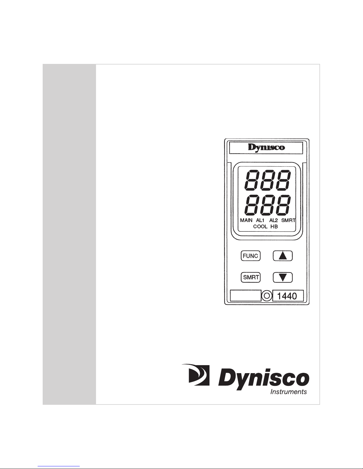
Model 1440
Microprocessor-based
Temperature Controller
Installation and Operation Manual
P/N 974073
06/02 Rev. C
ECO # 27007
Page 2

2
CONTENTS
Quick Start Instructions ....................................................................................................................3
1. Introduction ...............................................................................................................................6
2. Specifications ............................................................................................................................ 6
3. Front Panel Description ............................................................................................................10
4. Alarms ..................................................................................................................................... 12
5. Mounting .................................................................................................................................13
6. Wiring Guidelines ................................................................................................................... 15
7. Instrument Configuration .........................................................................................................21
8. Operating Instructions ............................................................................................................. 35
9. Error Codes ..............................................................................................................................51
10. Repair ......................................................................................................................................53
11. Warranty ................................................................................................................................. 53
Page 3
1440 Microprocessor-based Temperature Controller 3
MODEL 1440-2-3 QUICK START INSTRUCTIONS
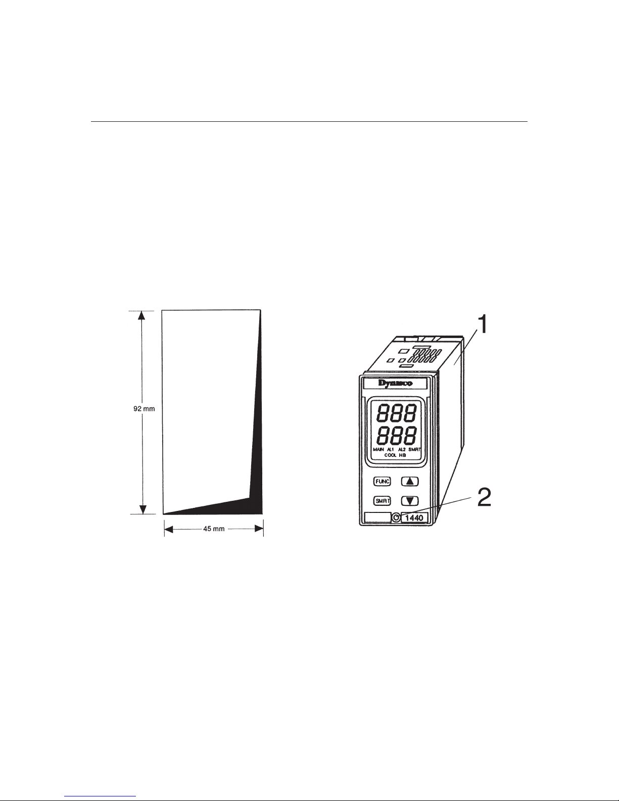
1. MOUNTING
• Prepare panel cutout to dimensions shown below.
• Remove instrument from case by turning captive safety screw (2) counter clockwise.
• Grasp the bezel and slide the instrument out of its case (1).
• Slide the supplied rubber gasket over the case.
• Slide the instrument case (1) into the panel cutout.
• Slide the panel mounting bracket over the instrument case.
• Tighten two screws on panel mounting bracket until case is securely mounted in panel cutout.
• Slide the instrument back into the case and tighten safety screw.
2. WIRING
• Connect an appropriate length of either thermocouple extension wire (e.g.Type J), OR 3 wire
RTD leads to the appropriate terminals as shown below.
• Connect Outputs for Heat/Cool. Note that Outputs are jumper selectable for Relay/SSR output.
Refer to Figure 15, Page 22 for jumper location.
• If a current transformer option is to be used for Heater Breakdown Alarm, connect to
appropriate terminals.
• Connect power to the appropriate terminals as shown below.
Page 4
4
3. INSTRUMENT CONFIGURATION
• Remove instrument from case by loosening safety screw, grab bezel and slide out of case.
• Refer to Figure 15, Page 22, for jumper selection of Relay/SSR selection and AL1 Cool relay NO/
NC selection. Default factory settings are Main/Relay, AL1 Cool/Relay Normally open.
• Locate jumper V2 in Figure 14, page 21 and place in the open position.
• Slide instrument back in case and apply power. Display will now show CnF.
• Press the FUNC button until P1 is displayed.
• Refer to Parameter List on page 23. Using the UP arrow, select appropriate P1 code for Input
type and standard range.
• Press the FUNC button until next parameter is displayed.
• Repeat for each parameter to be changed.
• When configuration is complete, remove instrument from case, place jumper V2 in the closed
position, return instrument into case and secure with safety screw.
• Apply power to instrument, Upper display will show process temperature, lower display will
show setpoint.
• Using UP and DOWN arrows, temperature setpoint can be adjusted.
• Refer to Manual page 36 in for Control Parameters if PID tuning is required.
• Instrument is now ready for use.
NOTE: The preceding Quick Start instructions are the basic settings required to install, wire, and
get the controller operating. It is assumed that the operator is familiar with PID temperature
controllers. Please refer to the complete installation and operation manual for additional
functions and instructions.
Page 5

1440 Microprocessor-based Temperature Controller 5
INDEX
How to: See Section Page
Wire the 1440 6 15
Configuration
Configuration 7 21
Calibration
General Guidelines for Calibration 8.7 43
Calibration Procedure 8.9 45
Operation
Operating Instructions 8 35
Alarms
Main Alarms 4.1 12
Heater Breakdown Alarms 8.5 43
Control Parameters
Control Parameters 8.1 36
Default Control Parameters 8.2 40
Security
Set Safety Lock 3 31
Error Codes
Error Codes 9 51
Instrument Repair
Repair the Instrument 10 53
Get Technical Assistance 10 53
Page 6

6
1. INTRODUCTION
The Model 1440 is a highly flexible, field or laboratory reconfigurable controller. This product’s
design has been implemented with up-to-date technology and accurate engineering. The following
is a summary of the features of the Model 1440:
• 1/8 DIN size (48 x 96 mm)
• IP 54 font protection
• SMART function for automatic self-tuning
• Measurement of the heater current consumption
• Heater breakdown alarm
• TC or RTD input with programmable range
• Programmable transfer ramp between the set points
• Programmable output maximum rate of change
• Output power limiter with programmable time duration
• Two independent alarms programmable as process, band or deviation alarms
• Control outputs: relay or solid state relay (SSR) drive programmable as heating or heating and
cooling controls
• Output power-off
• Direct access to the set point modification
• Switching power supply (for 100 to 240 VAC sources)
2. SPECIFICATIONS
2.1 GENERAL
Case: PC/ABS, black; self-extinguishing, level V-0, per UL94
Front panel: IP 54 protection
Installation: Panel mounting by means of tie rods; instrument removable from
case with a screwdriver
Rear terminal block: Screw terminals; terminal identification labels, connection
diagrams and rear safety cover
Dimensions: 48 mm wide x 96 mm high x 89 mm deep
(DIN 43700)
Cutout: 45 x 92 mm
Weight: 600 g maximum
Page 7

1440 Microprocessor-based Temperature Controller 7
Upper display: 3 green LED digits, 7 segments with decimal point
10 mm high
Lower display: 3 orange LED digits, 7 segments with decimal point
10 mm high
Front indication: red LEDs for alarms and instrument status indication
Power supply: 100 to 240 VAC power source, 50/60 Hz
Power Supply Variations: -15 to +10%
Power consumption: 6 VA maximum
Insulation resistance: >100 MΩ for 500 VDC (IEC 348)
Insulation voltage: 1500 V according to IEC 348
Conversion: Dual slope integration with autozero
Resolution 30,000 counts
Sampling time: 500 msec.
Accuracy (@25°C amb. temp.) +0.2% of the input span or +1°C
Common mode rejection ratio: 120 dB
Normal mode rejection ratio: 60 dB
Noise rejection: According to IEC 801-4 level 3
Temperature drift: <200 ppm/°C (Rj excluded); <400 ppm/°C for RTD input with -
19.9/99.9°C ranges
Operating temperature: 0 to +50°C
Storage temperature: -30 to +70°C
Humidity: 20 to 85% RH non-condensing
Protections: 1) WATCH DOG circuit for automatic restart
2) Internal switch for protection against tampering of configuration
and calibration parameters
Page 8

8
2.2 INPUTS
Thermocouple
Type: L,J,K,N programmable by front pushbuttons
Line resistance: 100Ω max, with error <+0.1% of the input span
Temperature units: °C of °F programmable
Reference junction: Automatic compensation of the ambient temperature from 0 to
+50°C
Burn-out: Up or down scale selectable
Calibration: According to IEC 584-1 and DIN 43710-1977 (TC type L)
Standard Ranges Table
TC Type Measuring Ranges
L 0 to +800°C 0 to +999°F
J 0 to +800°C 0 to +999°F
K 0 to +999°C 0 to +999°F
N 0 to +999°C 0 to +999°F
RTD (Resistance Temperature Detector)
Type: Pt 100-3-wire connection
Current 135 mA
Line resistance: Automatic compensation up to 20Ω/wire with <+0.1% error of the
input span for range -19.9 at 99.9°C; no measurable error for the
other ranges
Engineering units: °C or °F programmable
Burn-out: Up scale
Calibration: According to DIN 43760
Page 9

1440 Microprocessor-based Temperature Controller 9
Standard Ranges Table
RTD Type Measuring Ranges
RTD Pt 100 -199 to +500°C -199 to +999°F
RTD Pt 100 -19.9 to +99.9°C -21.6 to +217°F
Current Transformer Input (optional)
The 1440 controller is capable of measuring heater band current with the addition of a small remote
transformer.
Ranges: 25A and 100A
Indication: Use P/N 820754 for 25A range; use P/N 820755 for 100 A range
2.3 CONTROL ACTIONS
Control action: PID or SMART
Proportional band: 0.1 to 99.9% of the input span
When setting Pb = 0: Hysteresis
(for ON/OFF control action): 0.1 to 10.0% of the input span
Integration time: 10 seconds to 20 minutes; resolution 10 seconds; setting a value
greater than 20 minutes will disable the integration action
Differential time: <10 minutes
Heating cycle time: 1 to 200 seconds
Cooling cycle time: 1 to 200 seconds
Relative cooling gain: 0.20 to 1.00 seconds
NOTE: The Pb, ti, tc and parameters may be limited when the SMART function is enabled.
Overlapping/dead band: -20 to 50%
Rate of rise for set point variations: 1 to 100 units/minute
Page 10
10
2.4 OUTPUTS
Output 1 - Heating
Relay output with SPDT contact; contact rating 3 A/250 VAC with resistive load.
Logic voltages for SSR drive
Logic status 1: 24 V +20% @1 mA; 14 V + 20% @20 mA
Logic status 0: <0.5 V
Option output: Direct/reverse programmable
The selection between relay or SSR is made by internal jumper.
Output 2 - Cooling or Alarm 1
Relay output with SPST contact; contact rating 1.5 A/250 VAC with resistive load. Select the NC or
NO contacts by internal jumper.
Logic voltages for SSR drive:
Logic status 1: 24 V ±20% @1 mA; 14 V ±20% mA
Logic status 0: <0.5V
The selection between relay or SSR is made by internal jumper.
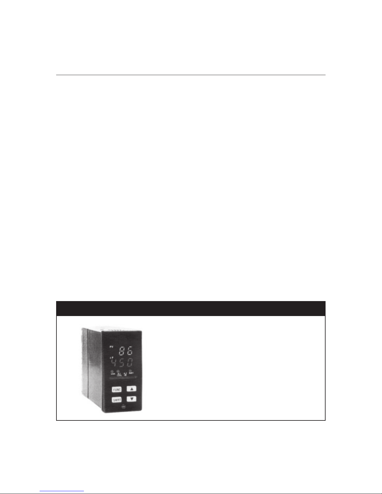
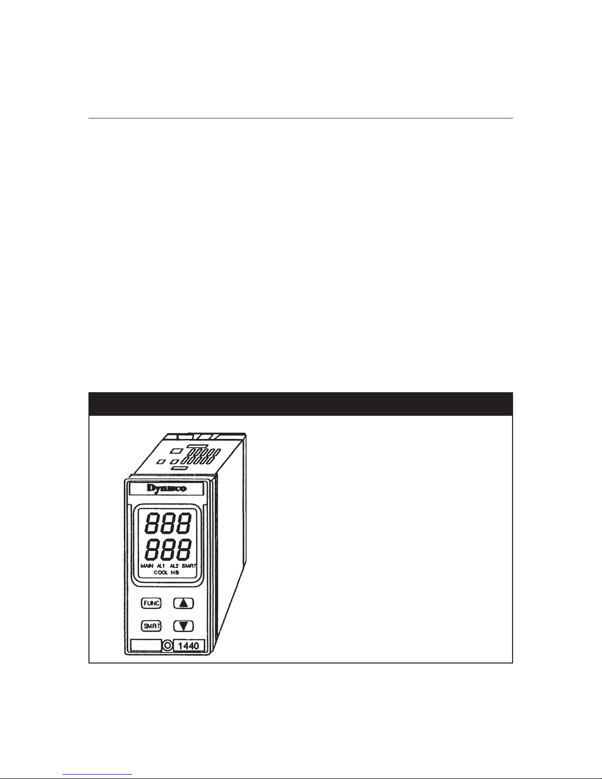
3. FRONT PANEL DESCRIPTION
Figure 1 illustrates the front panel of the Model 1440.
Fig. 1 1440 Temperature Controller Front Panel
Page 11

1440 Microprocessor-based Temperature Controller 11
3.1 INDICATOR DESCRIPTION
MAIN
Indicator
Indicator lit Main output is
AL1/COOL
Indicator
Indicator lit Cooling output is On or Alarm 1
AL2/HB
Indicator
Indicator lit Alarm 2 is in alarm condition
Indicator flashing Heater breakdown is in alarm condition
SMRT
Indicator
Indicator flashing First step of the SMART function is running
Indicator lit Second step of the SMART function is running
OFF
OFF
OFF
OFF
Main output is
OFF
On
Cooling output is
Alarm 2 and heater breakdown
SMART function is disabled
OFF
or Alarm 1
is not
in alarm condition
is in
alarm condition
are not
in alarm condition
3.2 DISPLAY DESCRIPTION
Upper Display
The upper display continuously shows the process variable in amperes. During the programming
procedure, this display shows the numerical value of the selected parameters or functions.
Lower Display
The lower display continuously shows the current set point value. Pressing the ▲ pushbutton for less
than 1.5 seconds causes the heater consumption in amperes to be shown. Pressing the ▲
pushbutton again causes the set point value to be re-shown. During configuration, calibration, and
parameter setup, the lower display will show the code of the selected parameter.
Page 12
12
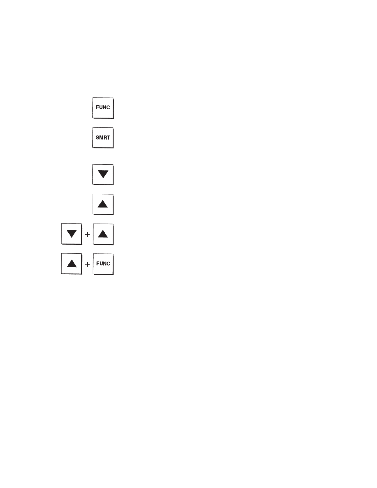
3.3 KEYBOARD DESCRIPTION
Selects the parameters. Pressing the FUNC pushbutton causes the
parameters to be shown sequentially on the upper and lower displays.
Simultaneously, the value of the previous parameter will be stored.
In operating mode, the SMRT pushbutton enables or disables the SMART
function. In configuration and calibration mode it is used to scroll the
configuration and calibration parameters backwards without storing the
modified value.
Decreases the parameter value. When the instrument is in operating mode,
it allows direct access to the set point modification.
Increases the parameter value. When the instrument is in operating mode,
it allows the display of the heater consumption or direct access to the set
point modification.
Loads the default control parameters.
Turns the control output
OFF
or On.
4. ALARMS
4.1 MAIN ALARMS
Two independent alarms are available, each of which can be configured in one of three modes, as
follows:
• Process alarm
• Band alarm
• Deviation high or deviation low
Action: Direct or Reverse Action
Threshold resolution: 1 digit
Alarm hysteresis: Programmable between 0.1% and 10.0% of the input span
Alarm indication: Two LEDs (Al1, Al2) lit for alarm ON
Alarm 1: See Outputs, page 18
Alarm 2: Relay output with SPST contact;
contract rating 2 A/250 VAC with resistive load
Page 13
1440 Microprocessor-based Temperature Controller 13
4.2 HEATER BREAKDOWN ALARM
This function uses a measurement (in amperes) of the main load consumption along with a user-set
alarm threshold to indicate either a partial or complete heater malfunction. This alarm output is
linked to Alarm 2 with a logical OR.
NOTE: This is supplied with the current transformer input option.
Threshold resolution: 1 digit
Alarm hysteresis: 1 digit
Alarm indication: LED Al2/HB flashes when alarm is On
Alarm output: See Alarm 2
5. MOUNTING
Select a mounting location where there is minimum vibration and the ambient temperature range is
between 0 and 50°C. The instrument can be mounted in a panel up to 15 mm thick with a
rectangular cutout of 45 x 92 mm. To mount the Model 1440, insert the instrument through the
panel cutout. While holding the instrument against the panel, slide bracket over case and tighten the
screws until the instrument is held tightly against the panel (see figure 2).
Fig. 2 Mounting the Model 1440
Page 14
14
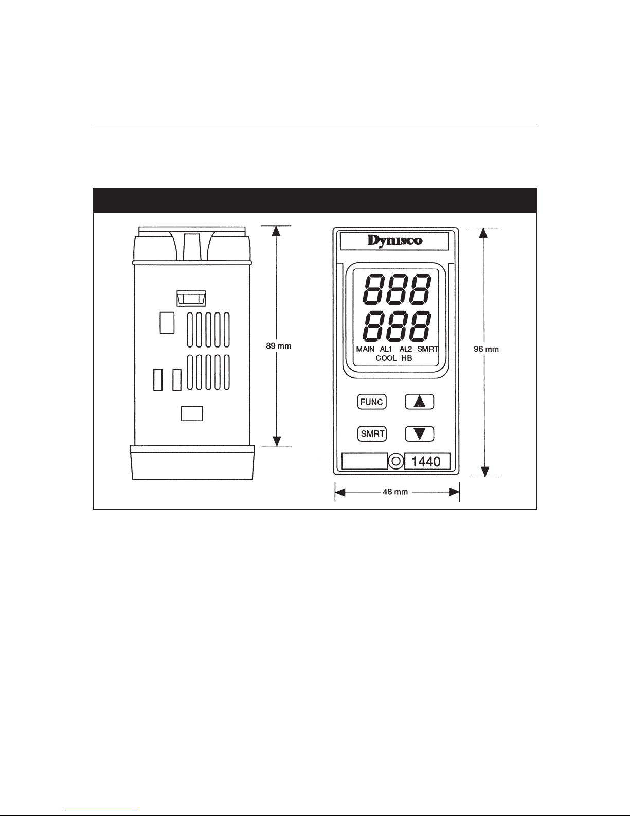
5.1 OUTLINE DIMENSIONS
Figure 3 shows the outline dimensions of the Model 1440.
Fig. 3 Outline Dimensions
Page 15
1440 Microprocessor-based Temperature Controller 15
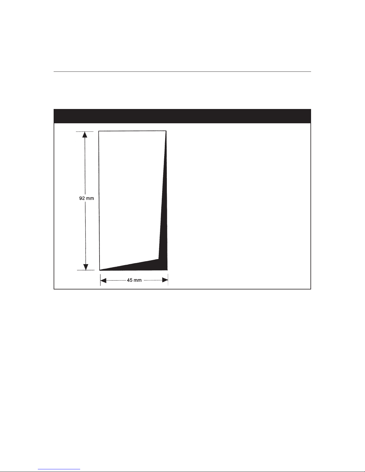
5.2 CUTOUT DIMENSIONS
Figure 4 shows the panel cutout dimensions of the Model 1440.
Fig. 4 Cutout Dimensions
5.3 VERTICAL PACKING
The minimum distance between cutouts is 20 mm.
Horizontal Packing for More Instruments in a Single Cutout
The total dimension of the cutout is the addition of the front dimensions minus 3 mm. The horizontal
dimension of the cutout equals (n x 48) - 3 mm, where n is the number if instruments to be packed
(maximum 10 instruments).
6. WIRING GUIDELINES
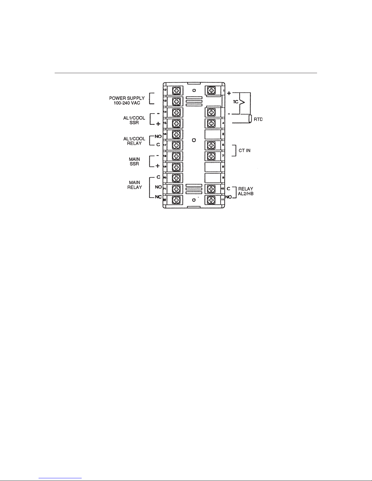
Connections should be made with the instrument housing installed in its proper location. Figure 5
illustrates the rear terminal block of the Model 1440.
Page 16
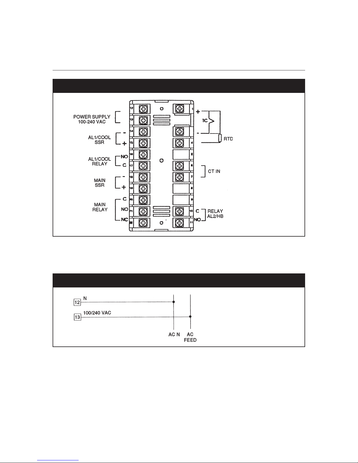
16
Fig. 5 Rear Terminal Block
6.1 POWER LINE AND EARTH WIRING
Figure 6 illustrates the power line wiring for the Model 1440.
Fig. 6 Power Line Wiring
6.2 INPUTS
Figure 7 illustrates the thermocouple input wiring for the Model 1440.
Page 17
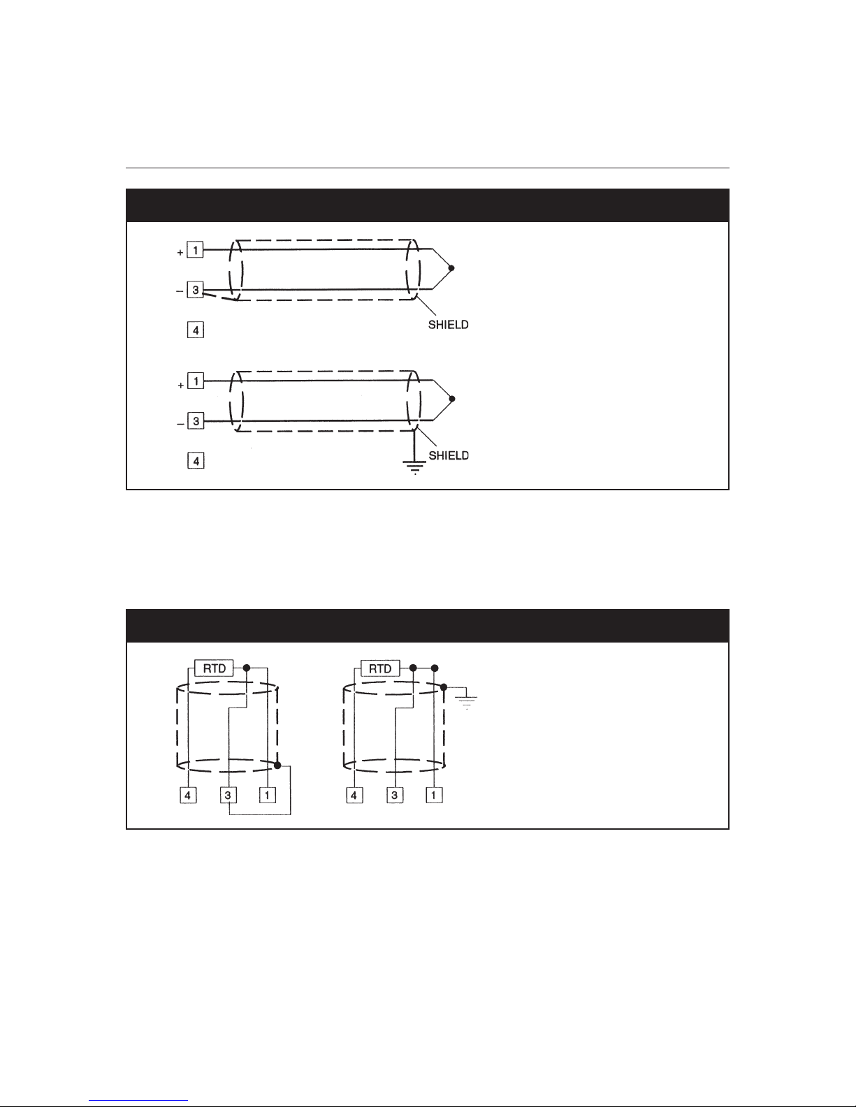
1440 Microprocessor-based Temperature Controller 17
Fig. 7 Thermocouple Input Wiring
NOTE: DO NOT run input wires together with power cables. For TC wiring, use proper
compensating cable, preferable shielded. If shielded cable is used, it should be grounded at
one point only.
Figure 8 illustrates the RTD input wiring for the Model 1440.
Fig. 8 RTD Input Wiring
NOTE: DO NOT run RTD wires together with power cables. If shielded cable is used, it should be
grounded at one point only. Use copper wires of appropriate size (see Product
Specifications). The resistance of the three wires must be the same
Any external components (e.g., zener barriers) connected between sensor and input terminals may
cause errors in measurement due to excessive and/or unbalanced line resistance or possible leakage
currents.
Page 18

18
Figure 9 illustrates the current transformer input wiring for the Model 1440.
Fig. 9 Current Transformer Input Wiring
6.3 OUTPUTS
Relay Outputs
Figure 10 illustrates the relay output wirings for the Model 1440
Fig. 10 Relay Output Wirings
The relay output is not protected with a snubber network.
Page 19

1440 Microprocessor-based Temperature Controller 19
Relay Output Contact Rating (Resistive Load)
1 3 A/250 VAC
2 1.5 A/250 VAC
3 2 A/250 VAC
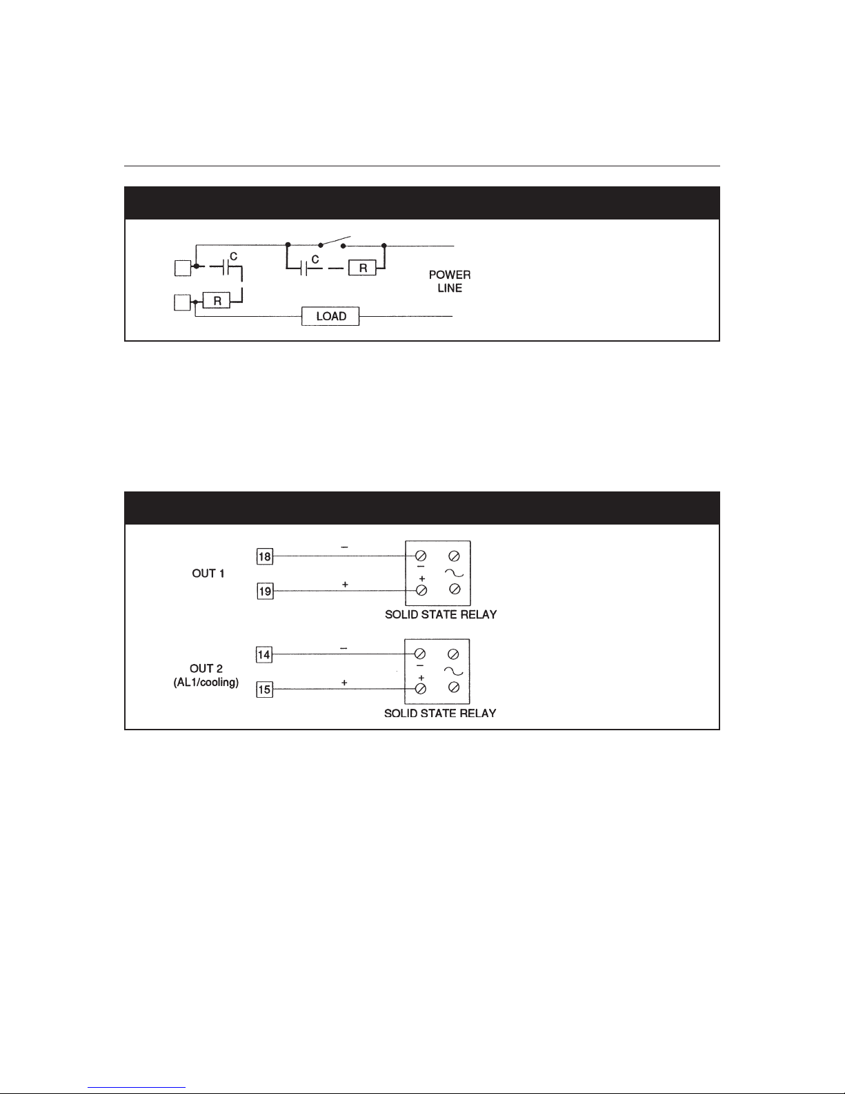
Inductive Loads
NOTE: The following recommendations should be followed to avoid serious problems, which may
occur when using relay outputs for driving inductive loads.
When switching inductive loads, high voltage transients may occur. These transients may introduce
disturbances, which can affect the performance of the Model 1440 through the internal contact.
Whenever an inductive load is switched by instrument contacts, an external network should be
connected across the terminals as near as possible to the terminals (see Figure 11).
Fig. 11 External Protection for an Inductive Load
The values of capacitor [C] and resistor [R] are shown in the following table.
Load Current C (µF) R (Ω) Resistance Power (Ω) Resist. And Capac. Voltage
<40 mA 0.047 100 1/2 260
<150 mA 0.1 22 2 260
<0.5A 0.33 47 2 260
<1A 0.47 47 2 260
The same problem may occur when a switch is used in series with the internal contact, as shown in
Figure 12.
Page 20
20
Fig. 12 External Switch in Series with Internal Contacts
In this case, it is recommended that an additional RC network be installed across the external
contact as shown in Figure 12. The cable involved in relay output wiring must be as far away as
possible from input and communication cables.
6.4 VOLTAGE OUTPUTS FOR SSR DRIVE
Figure 13 illustrates the SSR drive output wiring for the Model 1440.
Fig. 13 SSR Drive Output Wiring
The voltage outputs for the SSR drive are time proportional outputs. Logic voltages for SSR drive:
Logic status 1: 24V ±20% @1 mA; 14 V ±20% @ 20 mA
Logic status 0: <0.5V
NOTE: These outputs are not isolated. Isolation between instrument outputs and power supply must
be ensured by the external solid-state relay. The relay output and SSR output are mutually
exclusive. To activate the SSR output, first deactivate the relay by setting dipswitches J304
and J305 as shown in Figure 15.
Page 21

1440 Microprocessor-based Temperature Controller 21
7. INSTRUMENT CONFIGURATION
7.1 PRELIMINARY
Before actual operation of the Model 1440 controller, an initial configuration of the unit is required.
Proceed as follows:
1. Remove the unit from its enclosure by removing the front panel captive screw and pulling the
unit from the case.
2. Locate the internal dipswitch, V2 (Figure 14), and set the switch to the open condition.
3. Re-install the controller into its case and follow the Configuration Procedure.
Fig. 14 Internal Dip Switch Location
In the process of configuring or reconfiguring the Model 1440, the jumper shown in Figure 15 may
have to be accessed.
Page 22

22
Fig. 15 Jumper Locations
7.2 CONFIGURATION PROCEDURE
Once the internal dip switch has been set as described in Figure 14, proceed as follows:
1. Switch the instrument On. The upper display should show
NOTE: If
2. Press the FUNC pushbutton to start the configuration procedure.
3. The lower display will show the parameter code (e.g., P1 - P2) and the upper display will show
4. To modify this value press ▲ or ▼ to obtain the desired setting.
5. When the upper display shows the new setting, press the FUNC pushbutton to store the value
CAL
is indicated in the display, press the ▲ pushbutton to return to the configuration
mode.
the previously stored value.
and go to the next parameter. (The values are stored only when the FUNC pushbutton is
depressed.)
CnF
.
Page 23

1440 Microprocessor-based Temperature Controller 23
The SMRT pushbutton can be used to scroll backwards through the configuration parameters
without affecting the previously modified value.
7.3 BASIC CONFIGURATION
The following is a list of the basic configuration parameters. Some of these parameters may be
skipped, depending on the previous setting.
P1 - Input type and standard range
0 = TC type L Range 0/+800°C
1 = TC type J Range 0/+800°C
2 = TC type K Range 0/+999°C
3 = TC type N Range 0/+999°C
4 = RTD type Pt100 Range -199/+500°C
5 = RTD type Pt100 Range -19.9/+99.9°C
8 = TC type L Range 0/+999°F
9 = TC type J Range 0/+999°F
10 = TC type K Range 0/+999°F
11 = TC type N Range 0/+999°F
12 = RTD type Pt100 Range -199/+999°F
P2 - Initial scale value
Not available when P1=5. The initial and full scale values are used by the PID algorithm to calculate
the input span.
P3 - Full scale value
Not available when P1=5. The initial and full scale values are used by the PID algorithm to calculate
the input span. The minimum input span (P3 - P2) is:
300°C or 600°F for TC input
100°C or 200°F for RTD input
P4 - Output configuration
H
= Heating only
HC
= Heating/cooling
P5 - Heating output type
rEL
= Relay
SSr
= SSR
Page 24

24
The setting P5 =
The setting P5 =
P6 - Cooling element
Available only when P4 = HC.
Air
= air
OIL
= Oil
H2O
= Water
The setting P6 =
The setting P6 =
The setting P6 =
0.4.
P7 - Alarm 1
Available only when P4 = H.
0
= Not provided
1
= Process Alarm
2
= Band alarm
3
= Deviation alarm
rEL
forces the cycle time parameter to 20 seconds.
SSr
forces the cycle time parameter to 2 seconds.
Air
forces the cooling cycle time to 10 seconds and the relative cooling gain to 1.
OIL
forces the cooling cycle time to 4 seconds and the relative cooling gain to 0.8.
H2O
forces the cooling cycle time to 2 seconds and the relative cooling gain to
Pages 24 through 28 graphically represent the relay actions for the process band and deviation
settings.
High alarm.
Direct Action.
Page 25

1440 Microprocessor-based Temperature Controller 25
Low alarm.
Direct action.
Band alarm with neutral zone off with respect to the set point.
Direct Action.
Threshold is expressed as Deviation.
(Measure - Set point = Deviation)
Page 26

26
Band alarm with neutral zone on with respect to the set point.
Direct action.
Threshold is expressed as Deviation.
(Measure - Set Point = Deviation)
Page 27

1440 Microprocessor-based Temperature Controller 27
High deviation alarm.
Direct Action
Threshold is expressed as Deviation.
(Measure - Set Point = Deviation)
Page 28

28
Low deviation alarm.
Direct Action.
Threshold is expressed as Deviation.
(Measure - Set Point = Deviation)
Reverse Action (P21 = r) works only on the relay status:
DIRECT ACTION
(P21 = d)
REVERSE ACTION
(P21 = r)
Indicator Relay Status
On
OFF
On
OFF
ENERGIZED
DE-ENERGIZED
DE-ENERGIZED (fail safe alarm)
ENERGIZED
Page 29

1440 Microprocessor-based Temperature Controller 29
P8 - Alarm 1 operating mode
Available only when P7 is different from 0 and P4 = H.
H
= High alarm (external for band alarm)
L
= Low alarm (internal for band alarm)
P9 - Alarm 1 standby
Available only when P7 is different from 0 and P4 = H.
OFF
= Standby disabled
On
= Standby enabled
This function allows the alarms to be put in standby condition at the instrument start up or to impose
a standby condition on the band alarms or deviation alarms after a set point modification.
In both situations, the instrument disables the alarm indication until the process variable is reached
for the first time, under the following conditions:
• For the process alarm and start up, only the process variable must reach the alarm threshold.
• For the band alarm, the process variable must reach the alarm band (or the new alarm band
generated by the new set point).
• For the deviation alarm, the process variable must reach the deviation area (or the new
deviation area generated by the new set point).
P10 - Alarm 2
0
= Not provided
1
= Process alarm
2
= Band alarm
3
= Deviation alarm
The relay output of Alarm 2 is also used as a relay output by the heater breakdown function (OR
condition).
P11 - Alarm 2 operating mode
Available only when P10 is different from 0.
H
= High alarm (external for band alarm)
L
= Low alarm (internal for band alarm)
For other details, see Alarm 1 examples.
Page 30

30
P12 - Alarm 2 standby
Available only when P10 is different from 0.
OFF
= Standby disabled
On
= Standby enabled
P13 - Type of offset applied on the measured value
When P13 = 0, the offset (P14) is constant over the entire range. When P13 is different from 0, P13
shows the application point of the offset value set by parameter P14. When P14 is set to 0, there is
no offset.
P14 - Offset value
When P13 = 0, P14 is programmable in engineering units from -20% to +20% of the input range.
= no offset. When P13 is different from 0, P14 is programmable from -20% to +20% of the value of
P13. Refer to Figure 16.
0
Fig. 16 Offset Values
P15 - Threshold of the Soft Start Function
Threshold value, in amperes, for the automatic start of the output power limiting Soft Start function.
At instrument start up, if the measured value is lower than the threshold value, the Soft Start function
will be enabled; otherwise it will be disabled. The instrument will not take into account this
parameter when the
is always enabled.
P16 - Current measurement
LOL
parameter (see Control Parameters) is set to infinity and the power limiting
OFF
= Current measurement disabled
= The current measurement will be made during the On period (logic status 1 for SSR or
relay energized for relay output)
= The current measurement will be made during the
relay de-energized for relay output.
OFF
period (logic status 0 for SSR or
Page 31

1440 Microprocessor-based Temperature Controller 31
P17 - Current transformer range
Available only if P16 is different from
10
= 10A
25
= 25A
50
= 50A
100
= 100A
P18 - Safety lock
0 = Safety lock disabled (all the parameters can be modified)
1 = Safety lock always enabled (only parameter SP may be modified)
2 to 499 = Parameter SP is always modifiable and this code is the safety key used to access the
other operating parameters’ modification
500 to 999 = Parameters SP, A1 and A1 are always modifiable and this code is the safety key used
to access the other operating parameters’ modification
When the standard configuration procedure is completed, the instrument shows on both displays. If
no other settings are required, press the FUNC pushbutton. The instrument returns to the beginning
of the configuration procedure. This ends the basic configuration procedure. If a complete
configuration is desired, press the ▲ or ▼ pushbutton and set the 217 code on the upper display.
NOTE: Setting the 217 code must be performed in order to perform an Advanced Configuration.
OFF
.
7.4 ADVANCED CONFIGURATION
Press the FUNC pushbutton. The instrument will go to the advanced configuration procedure and it
will show the following additional parameters:
P19 - Main output action (see Figure 17 on next page)
Available only when P4 = H.
r
= Reverse (heating)
d
= Direct (cooling)
When P4 = HC, this parameter is forced to r.
Page 32

32
Fig. 17 Actions of the Alarm Relays
P21 - Action of the Alarm 1 relay (see Figure 17)
This parameter is available only if P7 is different from 0 and P4 = H.
r
= Reverse (relay de-energized in alarm condition)
d
= Direct (relay energized in alarm condition)
P22 - Action of the Alarm 2 relay (see Figure 17)
This parameter is available only if P10 is different from 0 and P16 is different from
r
= Reverse (relay de-energized in alarm condition)
d
= Direct (relay energized in alarm condition)
P23 - Automatic modification of relative cooling gain
OFF
= The SMART function will not modify the relative cooling gain parameter
On
= The SMART function will modify the relative cooling gain parameter
P24 - Output maximum rate of change
This parameter allows the maximum rate of change of the power output to be set. P24 is
programmable from 1 to 10% of the control output. If set over 10%, the instrument blanks the upper
display and the output variations have no limit.
OFF
.
Page 33

1440 Microprocessor-based Temperature Controller 33
P25 - Protect parameter visualization
This parameter is available only if P18 is different from 0.
OFF
= All the protected parameters cannot be displayed
On
= The parameter values can be displayed
P26 - SMART enabled/disabled
0
= The SMART function is always disabled (manual PID adjustment)
1
= The SMART function enabling/disabling
2
= The SMART function enabling/disabling is protected by the safety key
P27 - Maximum value of the proportional band set by the SMART function
is not
protected by the safety key
This parameter may be programmed over the range of the P28 or P29 value to
P28 - Minimum value of the proportional band set by the SMART function in heating control only
This parameter may be programmed from 1.0% to the P27 value
P29 - Minimum value of the proportional band set by the SMART function in heating/cooling only
This parameter may be programmed from 1.5% to the P27 value.
The advanced configuration procedure is now complete and the instrument should show
upper display.
99.9
.
CnF
on the
7.5 DEFAULT CONFIGURATION PARAMETERS
The configuration parameters can be loaded with predetermined default values. These data are the
typical values loaded in the instrument prior to shipment from the factory. To load the default values,
proceed as follows:
1. The internal dip switch, V2, (see figure 14) should be open.
2. The upper display will show:
3. Press the ▼ pushbutton; the lower display will show the firmware version:
Page 34
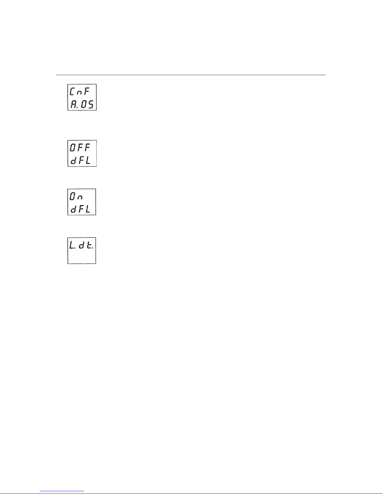
34
4. While maintaining pressure on the ▼ pushbutton, press the ▲ pushbutton. The display will
show:
5. Press the ▲ pushbutton again; the display will show:
6. Press the FUNC pushbutton; the display will show:
Appearance of the previous display means that the loading procedure has been initiated. After about
3 seconds the loading procedure is terminated and the instrument reverts to the display shown in
step 2 (above).
Page 35

1440 Microprocessor-based Temperature Controller 35
The following are the default parameters loaded during the above procedure:
Parameter Value Default Value
P1
P2
P3
P4
P5
P6
P7
P8
P9
P10
P11
P12
P13
P14
P15
P16
P17
P18
P19
P21
P22
P23
P24
P25
P26
P27
P28
P29
1
0
400
H
rEL
Air
1
H
OFF
0
H
OFF
0
0
0
OFF
10
0
r
d
d
OFF
10
On
2
30.0
1.0
1.5
J-type thermocouple with °C indication
0°C
400°C
Heating
Relay
Air
Process alarm
High alarm
Standby disabled
Not provided
High alarm
Standby disabled
Constant offset
No offset
Soft Start threshold
Current measurement disabled
10A
Safety lock disabled
Main output with Reverse Action
Direct Action of the alarm 1 relay
Direct Action of the Alarm 2 relay
Relative cooling gain will not be modified by the SMART function
Power output rate of change is 10% per second
All the parameters are displayed
SMART function enabling/disabling is protected by the safety key
30%
1.0%
1.5%
8. OPERATING INSTRUCTIONS
NOTE: To operate this unit as a controller, the internal dip switch, V2, located on the input card
(see figure 14) must be closed.
Page 36

36
It is assumed at this point that the Model 1440 has been correctly configured as detailed in
Instrument Configuration. In most applications as a controller, the Model 1440 will operate in the
normal display mode, where the upper display shows the measured variable and the lower display
shows the set point. If selected by the ▲ pushbutton, the lower display will show the heater current
amperes.
By pressing the FUNC pushbutton it is possible to scroll through all the parameters; their
abbreviated names will be shown on the lower display while their value is shown on the upper
display. To modify a parameter, first select the desired parameter with the FUNC pushbutton, then
set the new value with the ▲ or ▼ pushbuttons. Press the FUNC pushbutton to record the new
value and proceed to the next parameter.
The access time for parameter scrolling is limited to 10 seconds. Therefore, if no pushbutton is
pressed within this time, the instrument will automatically revert to the normal display mode.
The instrument does not always display all parameters. It selects the parameter in accordance with
the following:
• Instrument configuration in general (see Instrument Configuration)
• Parameter P25 in particular (see Configuration Procedure)
• The setting of the proportional band (see Control Parameters)
8.1 CONTROL PARAMETERS
The following is a list of all the available control parameters. Note that some parameters may not be
visualized according to the specific instrument configuration.
SP
- Set Point
Lower display:
Upper display: Set point value
Range: From parameter rL value to parameter rH value
nnn
- Safety Lock
Lower display:
Upper display:
To enable the safety lock, set a value different from P18 (see Parameters List) and press the FUNC
pushbutton. To disable the safety lock, set a value equal to P18 and then press the FUNC
pushbutton.
SP
nnn
On
(safety lock is enabled)
OFF
(safety lock is disabled)
Page 37

1440 Microprocessor-based Temperature Controller 37
A1, A2
- AlarmsThreshold
These parameters are present only if the relative alarm is configures.
Lower display:
Upper display: Alarm threshold value
Process alarm range: From P2 to P3 value
Band alarm range: 0 to 500 (F/C
Deviation alarm range: -199 to 500(F/C
h1, h2
- Alarms Hysteresis
Lower display:
Upper display: Value of alarm 1 or Alarm 2 hysteresis
Range: 0.1% (minimum 1 digit) to 10.0% of the
The instrument will use a hysteresis equal to the band alarm by setting a band alarm out of band
indication and an alarm hysteresis larger than the band alarm (minus 1 digit).
Pb
- Proportional band
Lower display:
Upper display: Value of proportional bank
Range: 1.0 to 99.9% of span for heating output;
When parameter Pb is set to 0, the control action becomes ON/OFF and parameters
OLP, Olh
and
tOL
A1, A2
h1, h2
input span (P3 - P2)
Pb
1.5 to 99.9% of span for heating/cooling output
t, td, C, C2, rC,
are skipped.
HS
- Hysteresis
This parameter is present if parameter Pb is equal to 0.
Lower display:
Upper display: Hysteresis for ON/OFF control action
Range: 0.1 to 10.0% of input span (P3 - P2)
ti
- Integral time
This parameter is present only if parameter Pb is different from 0.
Lower display:
Upper display: Integral time defined in minutes and seconds
Range: 1 minute and 20 seconds to 20 minutes; above the upper value, the display
HS
ti
Page 38

38
blanks out and the integral action is disabled.
Resolution: 10 seconds
td
- Differential time
This parameter is present only if parameter Pb is different from 0.
Lower display:
Upper display: Cycle time value for output 1
Range: 1 to 200 seconds
C2
- Output 1 (cooling) cycle time
This parameter is present only if P4 = HC and parameter Pb is different from 0.
Lower display:
Upper display: Cycle time value for output 2
Range: 1 to 200 seconds
rC
- Relative output 2 (cooling gain)
This parameter is present only if P4 = HC and parameter Pb is different from 0.
Lower display:
Upper display: Gain in proportional cooling band
Range: 0.20 to 1.00
C
C2
rC
Fig. 18 Gain in the Proportional Cooling Band
OLP
- Overlap/dead band between heating and cooling outputs
This parameter is present only if P4 = HC and parameter Pb is different from 0.
Page 39

1440 Microprocessor-based Temperature Controller 39
Lower display:
Upper display: A positive value means overlap between heating and cooling outputs;
Range: -20 to 50% of the proportional band
See Figure 19 on the next page.
OLP
A negative value means dead band between the two outputs
Fig. 19 Overlap/Dead Band Between Heating and Cooling Outputs
rL
- Set point low limit
Lower display:
Upper display: Value of set point low limit
Range: From the initial scale value (P2) to rH value
rH
- Set point high limit
Lower display:
Upper display: Value of set point high limit
Range: From rL value to the full scale value (P3)
rP
- Rate of change for set point variations
Lower display:
Upper display: Value of the rate of change imposed to set point variations
Range: 1 to 100 units per minute; above the maximum value, the display blanks so
rL
rH
rP
that the transfer is a step transfer
Page 40

40
OLH
- Control limit high limiter
This parameter is present only if parameter Pb is different from 0.
Lower display:
Upper display: Value of control output maximum limit
Range: 0 to 100% for heating output: -100 to 100% for heating/cooling output
t0L
- Time for Soft Start enabling
t0L
is a programmable time where the output level is limited to the value of parameter
time counts begin at instrument start up if the measured variable is less than the threshold value
programmed (parameter P15). This parameter is present only if parameter Pb is different from 0.
Lower display:
Upper display: Value of control output limiter time duration
Range: 1 to 100 minutes; above 100 minutes, the upper display blanks out and the
NOTE: Parameter
up.
Hdb
- Threshold for the heater breakdown function
This parameter is present only if parameter P16 is different from
Lower display:
Upper display: Value in amperes of the heater breakdown threshold
Range: Within the current transformer input span
OLH
0LH
. These
t0L
limiter will be enabled.
t0L
may always be modified but the new value will be active only at the next start
OFF
.
Hdb
8.2 DEFAULT CONTROL PARAMETERS
The control parameters can be loaded with predetermined default values. These data are the typical
values loaded in the instrument prior to shipment from the factory. To load the default values,
proceed as follows:
1. Close the internal dip switch (V2, Figure 14).
2. Disable the SMART function. The upper display will show the process variable while the lower
display will show the set point value or the current measurement.
3. Hold down the ▼ pushbutton and press the ▲ pushbutton; the display will show:
Page 41

1440 Microprocessor-based Temperature Controller 41
4. Within 10 seconds press the ▲ or ▼ pushbutton; the display will show:
5. Press the FUNC pushbutton; the display will show:
This means that the loading procedure has been initiated. After about 3 seconds, the loading
procedure is terminated and the instrument reverts to normal display mode.
The following is a list of the default parameters loaded during the above procedure.
Parameter Default Value
SP
Minimum range-value
nnn OFF
A1, A2
h1, h2
Pb
h5
ti
td
C
C2
rC
DLP
rL
rH
rP
OLH
tOL
Hbd
Minimum range-value for process alarms; 0 for deviation or band alarms
0.1%
4.0%
0.5%
04.0 (4 minutes)
1.00 (1 minute)
20 seconds for relay output; 2 seconds for SSR output
10 seconds if P6=
1.00 if P6=
0
Initial scale value
Full scale value
Blank display (step transfer)
100%
Blank display
50% of the full scale value
Air
Air
; 0.80 if P6=
; 4 seconds if P6=
OIL
; 0.40 if P6=
OIL
; 2 seconds if P6=
H20
H20
Page 42

42
8.3 SMART ALGORITHM
The SMART algorithm is a new self-tuning function of the instrument. It is used by the instrument to
automatically calculate and set the proportional band, the reset time, the derivative time and the
relative cooling gain values. The SMART algorithm can always be operative; in this case it will adapt
the control parameters continuously in order to perform the best control action.
To start the SMART function, depress the SMRT pushbutton when the instrument is in normal
display mode. The SMRT indicator will go blank or light according to the special function that is
being performed. When it is desired to use a fixed set of control parameters, press the SMRT
pushbutton again; the SMRT indicator will turn off.
During SMART function operation, the relative cooling gain (if present) is limited to the following
ranges:
Cooling Element Range
Air 0.85 to 1.00
Water 0.80 to 0.90
Oil 0.30 to 0.60
The SMART function uses a derivative action equal to 1/4 of the integral action.
The limits of the proportional band set by the SMART function are programmed by parameters P27,
P28 and P29.
8.4 OUTPUT POWER
This feature allows the Model 1440 control to be temporarily turned
output, depress the ▲ pushbutton, and while keeping it depressed press the function button. Keep
them depressed for more than 3 seconds. The upper display will show the measured value while the
lower display will show
When it is desired to return to the normal display mode, depress the ▲ pushbutton, and while
keeping it depressed, press the FUNC pushbutton. Keep them depressed for more than 3 seconds.
The instrument then goes automatically to the normal display mode.
NOTE: If the output is turned
algorithm (the SMRT indicator is flashing), the
instrument comes back to normal display mode, the
If the output is turned
algorithm (the SMRT indicator is lit), the
instrument comes back to the normal display mode, the
OFF
OFF
.
OFF
OFF
while the
while the
SMART
SMART
SMART
OFF
. To turn
function is performing the first part of the
SMART
function is performing the adaptive part of the
function will be aborted. When the
SMART
function will be stopped. When the
function will be disabled.
SMART
function will be activated.
OFF
the control
Page 43

1440 Microprocessor-based Temperature Controller 43
8.5 HEATER BREAKDOWN ALARM (OPTION)
This alarm allows continuous monitoring of the main load consumption and generation of an alarm
condition when the main load consumption is outside (either lower or higher than) the programmed
threshold. See parameter
pushbutton when the instrument is in normal display mode. The upper display will show the
measured value while the lower display will show the main load consumption (in amperes) followed
by the engineering units (A). To return to the normal display mode, press the ▲ pushbutton. When
an alarm condition is detected, the AL2/HB indicator will be flashing and the relay of the output 3
(Alarm 2 or heater breakdown alarm) will be activated.
Hbd
. To display the main load consumption, momentarily press the ▲
8.6 DIRECT ACCESS TO THE SET POINT MODIFICATION
The instrument allows modification of the set point value without the use of the FUNC pushbutton.
When a rapid set point modification is required, proceed as follows:
1. Press and hold the ▲ or ▼ pushbutton for more than 5 seconds; the set point value, shown on
the lower display will start to change.
2. Using the ▲ and ▼ pushbuttons, set the desired value.
3. When the desired value is reached, do not depress any pushbutton for more than 3 seconds; the
new set point will become operative after 3 seconds from the last pushbutton depression.
If during this procedure, it is desired to return to the previous set point value, press the FUNC
pushbutton; the instrument returns automatically to the normal display mode without storing the
new set point.
8.7 GENERAL GUIDELINES FOR CALIBRATION
CAUTION: The Model 1440 is calibrated at the factory. Calibrating in the field is not normally
required. If calibration is required, return the unit to the factory for calibration or adhere to these
calibration steps using only the equipment designated.
For a good calibration, observe these precautions:
• The instrument under calibration should be mounted in its case in order to keep the internal
temperature constant.
• The ambient temperature should be stable. Avoid any drift (e.g., due to air conditioning).
• The relative humidity should not exceed 70%.
• Minimum warm-up time must be 20 minutes.
• Operate in a noise-free environment, if possible.
• During calibration, connect one input at a time to the rear terminal block.
For this calibration procedure it is necessary to use calibrators with the following accuracy and
Page 44

44
resolution:
Accuracy
• TC input: +0.005%; output +0.001%; range: +5 mV
• RTD input: ±0.02%; ±0.0025 Ω/decade
• Cold junction compensation: better than 0.1°C
• Current transformer input: 0.1 mA AC RMS
Resolution
• TC input: 1 mV
• RTD input: 10 mΩ
• Cold junction compensation: better than 0.1°C
• Current transformer input: 0.1 mA AC RMS
8.8 INTERNAL DIP SWITCH LOCATION
To start the calibration procedure, the internal dipswitch, V2, must be open as shown in Figure 20.
Fig. 20 Internal Dip Switch Location
Page 45

1440 Microprocessor-based Temperature Controller 45
8.9 CALIBRATION PROCEDURE
8.9.1 FOREWORD
Calibration parameters are logically divided into groups of two parameters each:
Initial and final scale value. After each group, the calibration check is called for, but it also possible
to proceed without making a new calibration.
When only a calibration check is required, press the FUNC pushbutton twice when
on the display. The instrument will go directly to the specific group check. The lower display will
show the parameter code while the upper display will show On or
pushbuttons to select between On and
To go to the next parameter without modifying the calibration, press the FUNC pushbutton when
the display is showing
To set the parameter for calibration, press the FUNC pushbutton when the display shows On.
NOTE: By pressing the SMRT pushbutton, it is possible to go back to the previous parameter
without storing the new calibration.
OFF
.
OFF
.
OFF
. Use the ▲ and ▼
OFF
is shown
8.9.2 CALIBRATION CODES
The Model 1440 is originally calibrated by means of calibrators with high accuracy and resolution
(see General Guidelines for Calibration). The following is a complete list of calibration codes:
Code Parameter
tL
tH
t
rj
rj.
PL
PH
P.
AL
AH
A.
TC input initial scale value (0 mV)
TC input full scale value (50 mV)
TC input check
Cold junction compensation
Cold junction compensation check
RTD input initial scale value (0 Ω)
RTD input full-scale value (300 Ω)
RTD input check
Current transformer input initial scale value (0 mA AC)
Current transformer input full-scale value (50 mA AC)
Current transformer input check
8.9.3 HOW TO PROCEED
1. Switch the instrument On. The upper display will show
CnF
.
Page 46

46
2. Press the ▲ pushbutton. The upper display will show
3. Press the FUNC pushbutton to show the first calibration code on the lower display. Depress the
FUNC pushbutton until the desired calibration code is reached.
tL
- TC input initial scale value
1. Provide connections between the RTD/thermocouple calibrator and the instrument under test as
shown in Figure 21.
2. The upper display will show
3. Set calibrator to 0.000 mV. Press the ▲ pushbutton; the display will change to
4. After a few seconds, start the calibration by pressing the FUNC pushbutton.
The display blanks out to indicate that it is performing the calibration routine. At the end of this
calibration routine, the instrument will go to the next parameter.
OFF
, while tL will appear on the lower display.
CAL
.
On
.
Fig. 21 Connections from a Calibrator to an Instrument Under Test
tH
- TC input full scale value
1. Set the calibrator to 50.000 mV (see Figure 21).
2. Press the ▲ pushbutton; the upper display will show
3. After a few seconds, start calibration by pressing the FUNC pushbutton.
The display blanks out to indicate that it performing the calibration routine. At the end of the
calibration routine, the instrument will go to the next parameter.
t.
- TC input check
The display will show t. followed by a number showing the measured value in counts.
On
.
Page 47

1440 Microprocessor-based Temperature Controller 47
The calibration is correct if the indication is
1. Check the zero calibration by setting the calibrator to 0.000 mV. The readout must be
± 10 counts.
2. Check linearity at half scale by setting the proper value on the calibrator. The readout must be
t.15 000
3. Press the FUNC pushbutton.
rJ
- Cold junction compensation
NOTE: Make sure that parameters tL and tH are correctly calibrated before rJ calibration.
1. Measure the temperature close to terminals 1 and 3 using an appropriate measuring device (see
figure 22).
2. Wait a few minutes to allow temperature stabilization of the entire system (compensation cable,
sensor, calibrator and instrument).
3. Using the ▲ or ▼ pushbuttons, set a value equal to the temperature as measured in tenths of °C.
4. After a few seconds, start calibration by pressing FUNC pushbutton.
The display blanks out to indicate that it performing the calibration routine. At the end of this
calibration routine, the instrument will go to the next parameter.
± 10 counts.
OFF
t. 30 000
and rJ will appear on the displays.
± 10 counts.
t. 0 0 000
Fig. 22 Measuring the Temperature Close to Terminals 1 and 3
rJ
- Cold junction compensation check
The display will show
Make sure that the display readout is equal to the value read on the thermocouple. Press the FUNC
pushbutton, the instrument will go to the next parameter.
PL
- RTD input initial scale value
1. Connect a resistor box as shown in Figure 23.
rJ
. And the temperature in tenths of °C, measured by the
CJ
compensator.
Page 48

48
2. Set 0.00 Ω on the resistor box.
3. Press the ▲ pushbutton. The instrument will show
4. After a few seconds, start calibration by pressing the FUNC pushbutton.
The display blanks out to indicate that it is performing the calibration routine. At the end of this
calibration routine, the instrument will go to the next parameter.
On
and PL.
Fig. 23 Connections to a Resistor Box
PH
- RTD input full scale value
1. Set the resistor box to 300.00 Ω (see Figure 23).
2. Press the ▲ pushbutton. The displays will show
On
and PH.
3. Wait a few seconds, then press the FUNC pushbutton.
The display will go blank to indicate that it is performing the calibration routine. At the end of this
calibration routine, the instrument will go to the next parameter.
P.
- RTD input check
1. The display will show P. followed by a number showing the measured value in counts. Set the
resistor box to 300.00 Ω (see Figure 23). The calibration is correct if the indication is
±10 counts.
2. Check the zero calibration by setting 0.00 Ω on the resistor box; the display should show
000
±10 counts.
3. Check linearity.
The ratio between input signal and counts for RTD input is not linear. The correct ratio is shown in
the following table:
P. 30 000
Pt.00
Page 49

1440 Microprocessor-based Temperature Controller 49
Resistor Box Ω Display Counts
00 ±10 counts
100 10153 ±10 counts
200 20151 ±10 counts
300 30000 ±10 counts
5. Press the FUNC pushbutton to proceed to the next parameter.
AL
- Current transformer input initial scale value
1. Connect the instrument to a 0-5- mA AC source as shown in Figure 24.
Fig. 24 Connections from a Calibrator to an Instrument Under Test
2. The display will show AL and
3. Set 0.00 mA on the mA AC generator.
4. Depress the ▲ pushbutton until the display changes to
5. After a few seconds, start calibration by pressing the FUNC pushbutton.
The display will go blank to indicate that it is performing the calibration routine. At the end of this
calibration routine, the instrument will go to the next parameter.
AH
- Current transformer input full scale value
1. The display shows AH and
2. Set 50.00 mA RMS on the mA AC generator.
3. Press the ▲ pushbutton until the display changes to
4. After a few seconds, start calibration by pressing the FUNC pushbutton.
OFF
OFF
.
.
On
.
On
.
Page 50

50
The display will go blank to indicate that it is performing the calibration routine. At the end of this
calibration routine, the instrument will go to the next parameter.
A.
- Current transformer input check
1. The display should show A.. followed by a number of counts. The calibration is correct if the
indication is
2. Check the zero calibration by setting 0.00 mA on the mA AC generator; the readout should be
A. 0 000
A. 1000
±10 counts.
± 10 counts.
3. Check linearity at half scale by setting 25.00 mA on the calibrator. The readout must be
10 counts.
4. Press the FUNC pushbutton.
The calibration procedure is now complete.
If it desired to go to the configuration procedure, press the ▲ pushbutton. The upper display will
show
CnF
and the instrument will be in configuration mode. If the previous configuration is correct,
switch the instrument
Instructions.
OFF
and set the V2 switch according to the Preliminary Operating
A. 500
8.10 OUT OF RANGE INDICATIONS
The instrument shows Under Range and Over Range conditions with the following messages on the
upper display:
Burn-out conditions will be shown as Over Range.
±
For TC input it is possible to select an Under Range indication. See Open Input Circuit for more
information.
NOTE: When an Over Range or an Under Range condition is detected, the instrument operates as
if in the presence of the maximum or the minimum measurable value, respectively.
To eliminate the Out of Range condition, proceed as follows:
1. Check the input signal source and the connecting line.
Page 51

1440 Microprocessor-based Temperature Controller 51
2. Make sure that the input signal is in accordance with instrument configuration. Otherwise,
modify the input configuration (see Instrument Configuration).
3. If no errors are detected, send the instrument back to the supplier for examination.
8.11 OPEN INPUT CIRCUIT
The Model 1440 is able to identify an open circuit for TC and RTD inputs. The open input circuit
condition for RTD input is shown by an Over Range indication.
For TC input, it is possible to select an Over Range indication (standard) by setting CH2 closed and
SH2 open; otherwise it is possible to select the Under Range indication by setting CH2 open and
SH2 closed. Both solder pads are located on the solder side of the CPU board (Figure 25).
Fig. 25 CH2 and SH2 Locations
9. ERROR CODES
Diagnostics are made at instrument start up and during the normal mode of operation. If a fault
condition (error) is detected, the lower display will show the message
Err
while the upper display
Page 52

52
shows the relative error code. Some errors reset the instrument; if the error persists, send the
instrument back to the supplier.
The following is a list of possible errors, their causes, instrument output conditions and possible
remedies, in numerical order.
Err 100
- EEPROM memory writing error.
After 2 seconds the instrument restarts automatically.
Send the instrument back to the supplier.
Err 150
- General hardware error on the CPU card.
Send the instrument back to the supplier.
Err 200
- Protect register memory error.
The instrument repeats this check every 2 seconds.
Set the V2 switch in open condition.
Switch on the instrument.
Set the V2 switch in closed condition; this error must be deleted.
If this error persists, send the instrument back to the supplier.
From
Err 201 to Err 229
- Wrong configuration parameter value.
The two less significant digits show the number of the wrong configuration parameter.
Return to the configuration procedure and check the values.
Err 301
- RTD calibration error.
Return to the calibration procedure and check the PL and PH calibrations.
Err 305
- Thermocouple input calibration error.
Return to the calibration procedure and check the tl and th calibrations.
Err 307
- Reference junction calibration error.
Return to the calibration procedure and check the rJ calibration.
Err 310
- Current transformer input calibration error.
Return to the calibration procedure and check the AL and AH calibrations.
Err 400
- One or more control parameters are Out of Range with respect to the allow values.
This error may appear at instrument start up.
Press the ▲ and ▼ pushbuttons momentarily and load all the default parameters.
Reset the parameter settings.
Err 500
- Autozero error.
The instrument measures an internal autozero value too negative or too positive.
The instrument makes this check every 30 seconds.
If this error persists, send the instrument back to the supplier.
Page 53

1440 Microprocessor-based Temperature Controller 53
Err 502
The instrument cannot make the cold junction compensation.
This error may appear during the operative mode.
Check the ambient temperature and, if necessary, recalibrate the unit.
If this error persists, send the instrument back to the supplier.
Err 510
This error may appear during the calibration procedure.
Check the input value and, if necessary, recalibrate the unit.
If this error persists, send the instrument back to the supplier.
- Cold junction measurement errors.
- Wrong measured value during the calibration procedure.
10. REPAIR
Questions concerning warranty, repair cost, delivery, and requests for a RA# should be directed to
the Dynisco Repair Department, 508-541-9400 or email: repair@dynisco.com. Please call for a
return authorization number (RA#) before returning any product. Damaged products should be
returned to:
DYNISCO INSTRUMENTS
Attn: RA # _______________
38 Forge Parkway
Franklin, MA 02038
For technical assistance please call 800-221-2201 or 508-541-9400 or fax 508-541-9436.
11. WARRANTY
This Dynisco product is warranted under terms and conditions set forth in the Dynisco Web Pages.
Go to www.dynisco.com and click on “Warranty” at the bottom of any page for complete details.
Page 54

NOTES:
Page 55

WARRANTY REGISTRATION CARD
MODEL NUMBER ______________________________________________________________
SERIAL NUMBER _______________________________________________________________
DATE PURCHASED _____________________________________________________________
PURCHASED FROM ____________________________________________________________
NAME _________________________________________________________________________
COMPANY ____________________________________________________________________
DIVISION______________________________________________________________________
STREET ________________________________________________________________________
CITY _____________________________ STATE _____________ ZIP __________________
COUNTRY _____________________________________________________________________
TELEPHONE _____________________________ FAX________________________________
My application is _______________________________________________________________
Is this your first purchase from Dynisco? YES __________ NO __________
How did you first hear of Dynisco? ADVERTISING________ REP __________
PREVIOUS USE ___________ COLLEAGUE _____________ DIRECTORY______________
I need further product information on ______________________________________________
I need application help on ________________________________________________________
Please send complete catalog _____________________________________________________
Tel.: 508-541-9400 Fax: 508-541-9436 E-mail: www.dynisco.com
PLEASE FOLD AND STAPLE OR TAPE
Page 56
DYNISCO INSTRUMENTS
38 FORGE PARKWAY
FRANKLIN, MA 02038
ATTN: MARKETING DEPT.
Place
Stamp
Here
 Loading...