

Dynex PF500-10, PF1000-10, PF2000 PF20002, PF3000-10, PF1300-10 Service Instructions Manual
...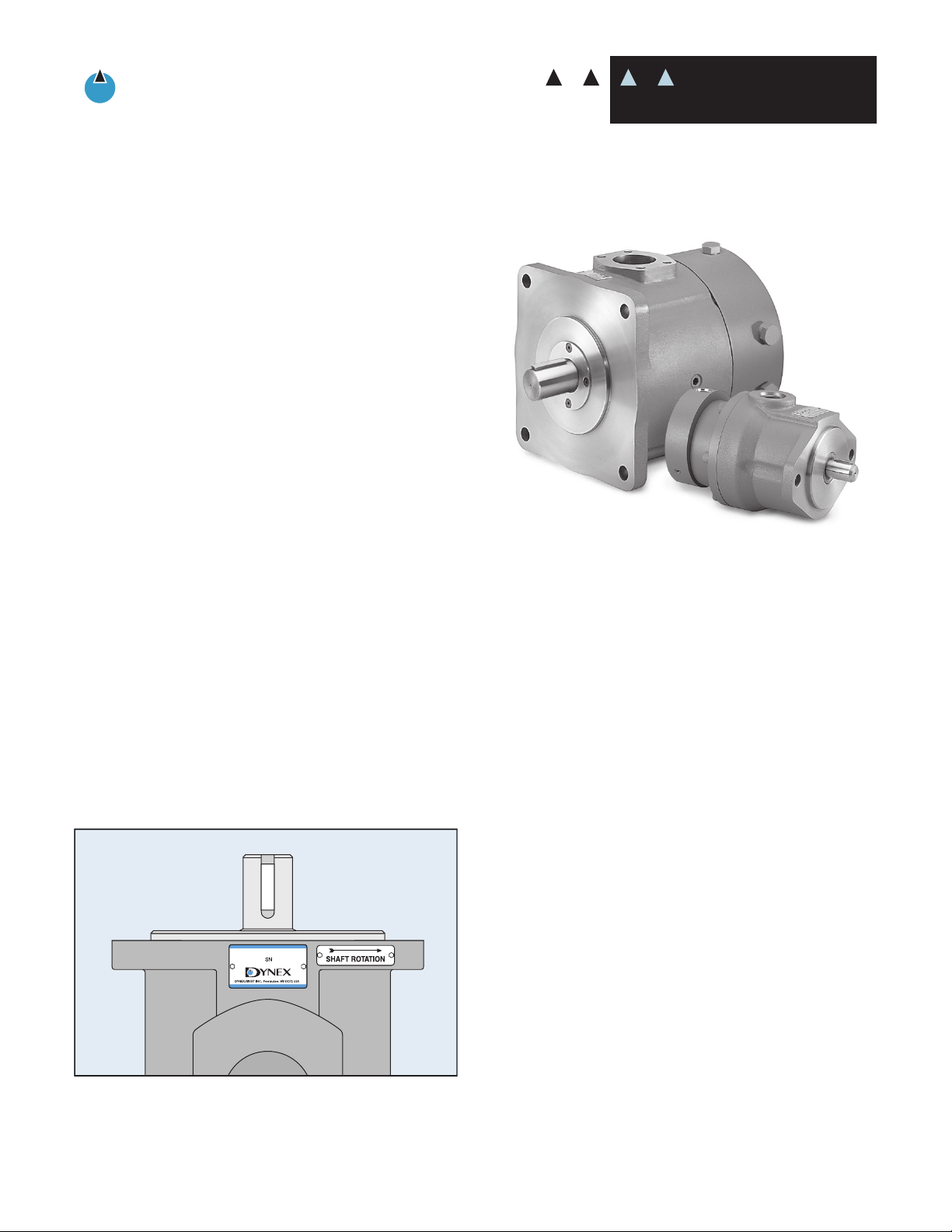
General Instructions:
Checkball Piston Pumps
High Pressure Hydraulics
D
YNEX
SERVICE
SERVICE GUIDELINES
These instructions assume a basic understanding of standard
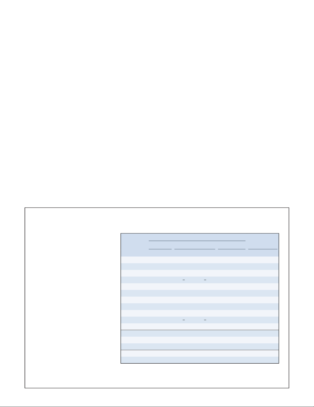
IMPORTANT: Refer to the "Minimum Inlet Pressure" table
INSTRUCTIONS
Pump
Fluid conditions outside the “Optimum” range may result in reduced output, requiring
Models with special mounting. Refer to "Bulletin PES".
Contact the sales department when operating with low-
IMPORTANT: Refer to “Fluid Recommendations” below.
Pressure or return line: 25 µ nominal.
IMPORTANT: Refer to "Air Bleed Procedure" on page 3.
WARNING: Side loading of the pump shaft, as with an
Dynex recommends that the shaft alignment be within
Crack the inlet fitting or remove the plug from the upper-
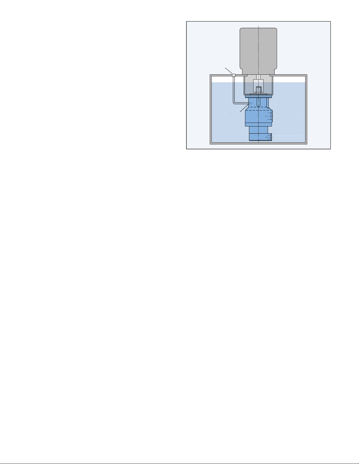
Remove the plug from the uppermost bleed port in housing
Remove the plug from the vertical bleed port (nearest to
Refer to FIGURE 2.
During installation, remove the plug from the vertical
Fill reservoir and allow all air to bleed from pump case.
IMPORTANT: In all cases, bleed air from the inlet hose

If excessive wear requires replacement, it may be more
®
Threadlocker

When storing for extended periods, keep the pump case
After filling the case, rotate the drive shaft several revolu-

Fixed Displacement Pumps:
10
0,7
10
0,7
15
� 1,0
10
0,7
10
0,7
10
0,7
�–
➃
10
0,7
➃
➃
➃
➃
➃
➃
➃
➃
10
0,7
10
0,7
15
1,0
➄
➄
➄
➄
Fixed Displacement Pumps for Water-Based Fluids:
Variable Delivery Pumps:
➄
➄
➄
➄
Pressure Compensated Pumps:
Values shown are based on fluid viscosity of 100 SUS (20 cSt) mineral oil, except pumps for water-based fluids as indicated.
Inlet pressures higher than 10 psig (0,7 bar) require a high-pressure shaft seal.
Minimum inlet pressure: 5 psi (0,4 bar) at 2200 rpm.
Minimum inlet pressure for Model PF3011: 5 psi (0,4 bar) at 2200 rpm and 7 psi (0,5 bar) at 2500 rpm; for Models PF3015 and PF3021: 7 psi (0,5 bar) at 2200 rpm
Minimum inlet pressure for Models PF6070 and PV6070: 10 psi (0,7 bar) at 2300 rpm maximum speed; for Model PF6080 and PV6080: 15 psi (1,0 bar) at 2200 rpm
Values shown are based on fluid viscosity of 33 SUS (1,9 cSt) water glycol fluid. Higher viscosity fluids may require pressurized inlet conditions then indicated.
Values shown are based on fluid viscosity of 33 SUS (1,9 cSt) water glycol fluid. Higher viscosity fluids may require pressurized inlet conditions then indicated.

SHOULDER

©
Dynex/Rivett Inc. Printed in U.S.A. Bulletin PSI.CB-030
x
v
Tel: +44 [0]
v
Tel: 262-6
v
Tel: 508-8
visit our web site:
 Loading...