


Internal All-In-One Card Reader
Lecteur de carte interne tout-en-un
Lector de Tarjetas Todo en Uno Interno
DX-CRD12
USER GUIDE
GUIDE DE L’UTILISATEUR • GUÍA DEL USUARIO

2
Contents
Dynex Internal All-In-One Card Reader
DX-CRD12
Contents
Introduction ......................................................................................2
Important safety instructions............................................................3
Card reader components ...................................................................3
Installing the card reader ..................................................................6
Using your card reader.......................................................................9
Specifications ..................................................................................10
Legal notices ...................................................................................11
Français ...................................................12
Español....................................................23
Introduction
Your card reader ‘s five slots support over 25 types of media cards and provides the
advantages of multiple card readers. It is ideal for installation in a 3.5-inch drive bay. Your
card reader accepts standard cards, such as Secure Digital (SD), Multi Media (MMC), Compact
Flash™ (CF), IBM® Microdrive, Smart Media™ (SM), Memory stick (MS), Memory stick pro,
++ picture card, and other compatible flash memory cards. Your card reader also accepts
small form-factor flash cards without the need for adapters, such as Mini-SD, RS-MMC,
MS-DUO, and the mini-sized T-flash (Micro SD) cards.
Features
Your card reader features:
• Five flash card slots supporting up to 25 types of media cards
• Efficient front direct access on a computer
• Easy mounting into a 3.5-inch drive bay
• Compliance with USB (Universal Serial Bus) 2.0 specification interface
• Compliance with USB mass storage device class specification
• Support for the RS-MMC 4.0 8-bit specification
• Support for small form-factor flash cards that typically require an adapter, such as
mini SD, RS-MMC, T-flash (Micro SD), and MS-Duo.
• Hot swappable Plug & Play capability
• Card slots that can be used at the same time for data exchange
• Support for four media card icons for easy drive recognition
• Swappable front bezel for color customization

Important safety instructions
Important safety instructions
Before getting started, read these instructions and save them for later reference.
• Before you install your card reader into your computer, read this user guide. In some
operating systems, the driver must be installed before you install your card reader.
• Do not drop or hit your card reader.
• Do not install your card reader in a location that is subject to strong vibrations because
vibration may damage your card reader.
• Do not disassemble or try to modify your card reader. Disassembly or modification may
void your warranty and could damage your card reader leading to a fire or electric
shock.
• Do not store your card reader in a damp location. Do not allow moisture or liquids to
drip into your card reader. Liquids can damage your card reader leading to a fire or
electric shock.
• Do not insert metal objects, such as coins or paper clips, into your card reader.
• Do not remove a card when the LED indicator shows data activity is in progress. You
may damage the card or lose data stored on the card.
• Your card read er is for general c omputer use. D o not use your card reader in a computer
that requires exceptional reliability, especially if a breakdown or malfunction of your
card read might jeopardize life or health, such as aerospace equipment, atomic power
control systems, traffic-related equipment, transportation equipment, industrial
robotics, combustion equipment, safety devices, and life-support systems.
Card reader components
3
Package contents
Make sure that you received:
• 1 card reader with USB 5-pin cable
• 4 mounting screws (ISO 3f 4mm)
• 1 extra front bezel
•1 utility CD
•1 user guide
Minimum system requirements
• IBM-compatible PC
• Pentium 133 MHz or higher processor
•CD drive
• 2 MB of hard drive space
• One available on-board 5-pin USB connector on the computer’s system board
• One available 3.5-inch drive bay
•Windows
® 98SE, Windows® ME, Windows® 2000, or Windows® XP
4
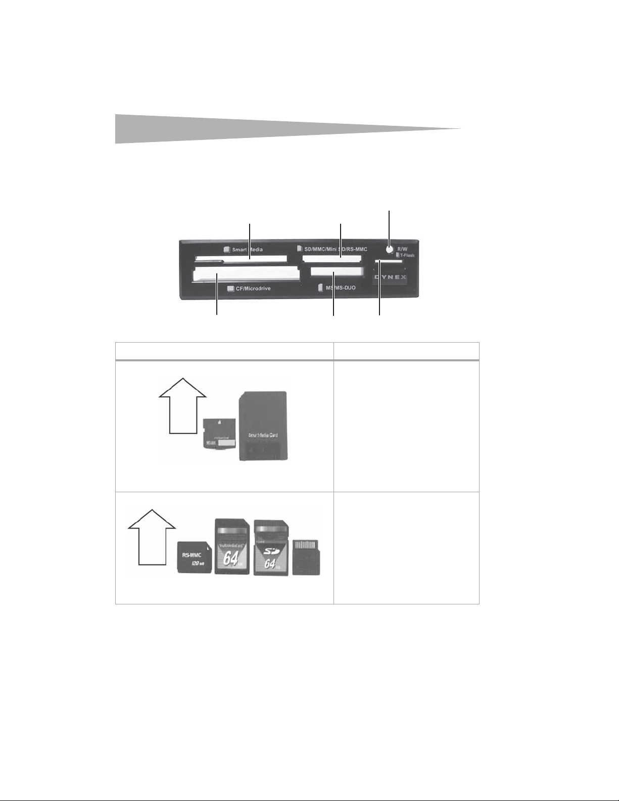
Front
Card reader components
Caution : Cards must be inserted into the correct slot and in the correct direction. Otherwise
you may damage the card or the slot.
SM/++ slot
SD/MMC slot
SM/++ slot
/++
CF/MD slot
Feature Description
SD/MCC/Mini SD/
RS-MMC slot
MS/MS-DUO slot T-Flash slot
LED
Insert Smart Media memory cards or ++
picture cards into this slot.
Note: Insert a ++ picture card into the right
side of the slot.
Note: The arrow shows the direction you
insert the card into the slot.
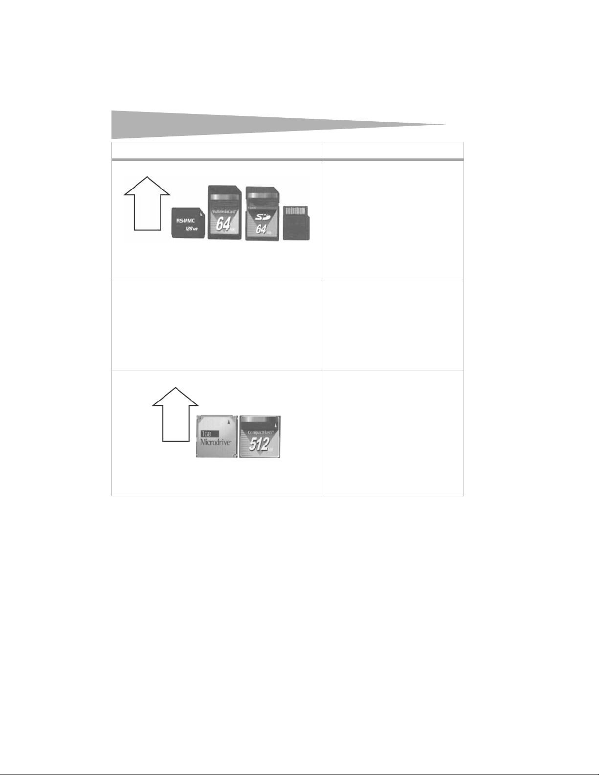
Insert Secure Digital (SD), Mini SD, Multi
Media (MMC), or RS-MMC cards into this slot.
Note: The Mini SD card’s gold contact area
must be facing up. Insert a Mini SD card into
the left side of the slot.
Note: The arrow shows the direction you
insert the card into the slot.
Card reader components
Feature Description
LED Indicates when a slot is reading from or
writing to a card.
LED off–Your card reader is not being used.
LED on–A card is inserted in one of the slots.
LED flashing–Data is being transferred to or
from a card and the hard drive or another
card.
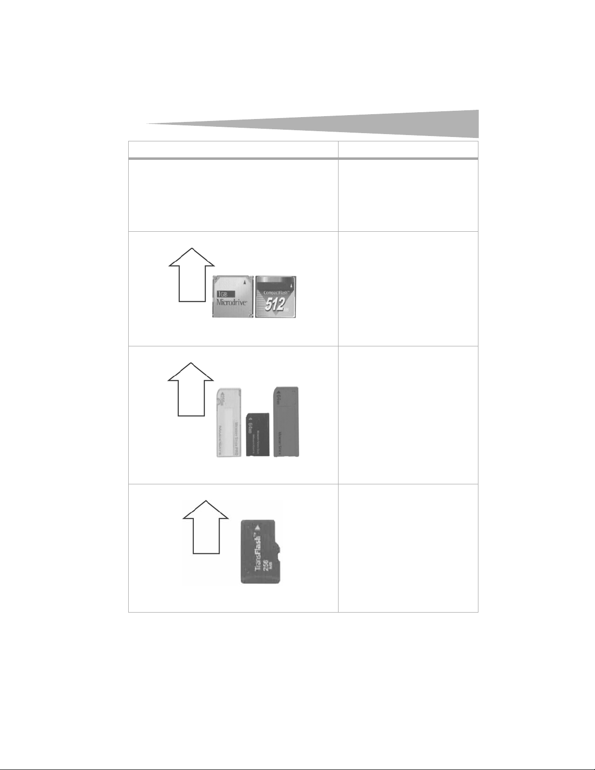
CF/MD slot
Note: The arrow shows the directi on you
insert the card into the slot.
MS/MS-DUO slot
Insert Compact Flash (type I/II), IBM
Microdrive, or Magicstor cards into this slot.
Insert Sony memory sticks or MS-Pro or
MS-DUO memory cards into this slot.
5
T-Flash s lot
Note: The arrow shows the directi on you
insert the card into the slot.
Insert Transflash or Micro SD memory cards
into this slot. No adapter is required.
Note: The T-flash slot and signal bus are
shared with the SD/MMC slot which means
that you cannot use both slots at the same
time.
Note: The arrow shows the directi on you
insert the card into the slot.
6
Installing the card reader
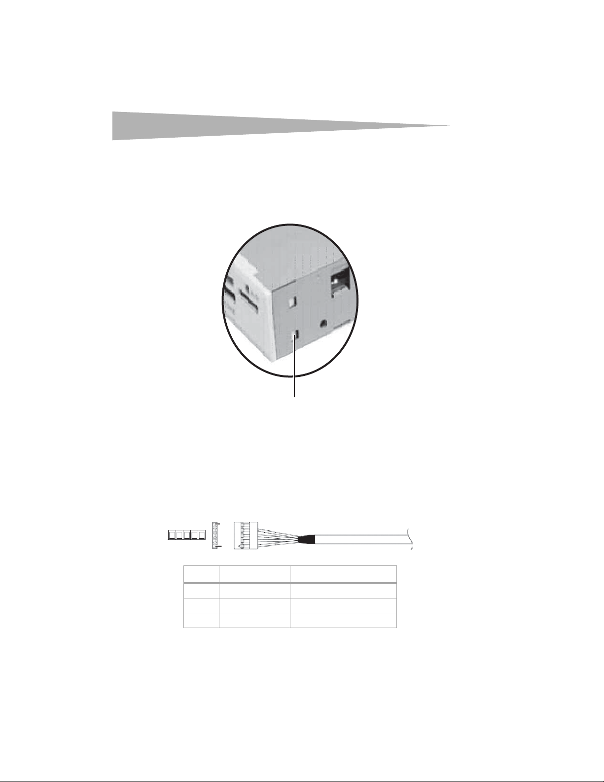
Changing the front bezel
To change the front bezel:
1 Use a stylus or pen-like tool to press the plastic clip on each side of your card reader to
remove the old bezel.
Plastic clip
Installing the card reader
2 Snap the new bezel into place.
Installing your card reader
USB pin cable assignment
Make sure that your computer’s system board connector is compatible with your card reader’s
USB connector by comparing your card reader’s USB connector with the connector on your
computer’s system board.
Card reader connector
P5
P1
Pin Cable color Function
P5 Shield GND
P4 Black GND
P3 Green D+
Installing the card reader
Pin Cable color Function
P2 White D–
P1 Red VBUS
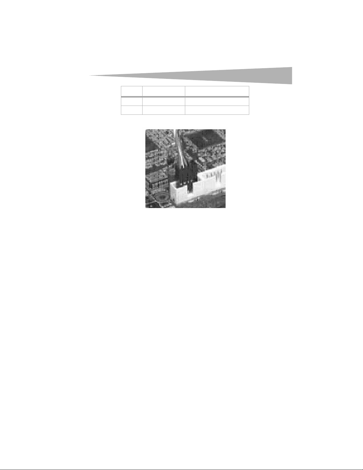
System board connector
Caution : Electrostatic discharge (static electricity) can d amage electronic compon ents. Make
sure t hat you are correctly grounded before you install your card rea der. Turn off your
computer, then touch a bare metal part of your computer, such as the back of the chassis
or power supply, to discharge any static electricity.
To install your card reader:
1 If you are installing your card reader into a computer running Windows 98SE, install
the driver before installing your card reader. For more information, see “Windows 98SE
and Windows ME” on page 9.
2 Make sure that you are correctly grounded by touching a bare metal part of your
computer, such as the back of the chassis or power supply.
3 Turn off your computer and disconnect the power cord.
4 Open your computer’s cover. For more information, see the documentation that came
with your computer.
5 Make sure that your computer’s system board corrector is compatible with your card
reader’s USB connector. For more information, see “USB pin cable assignment” on
page 6.
6 Carefully slide your card reader into the empty drive bay.
7
8
Installing the card reader
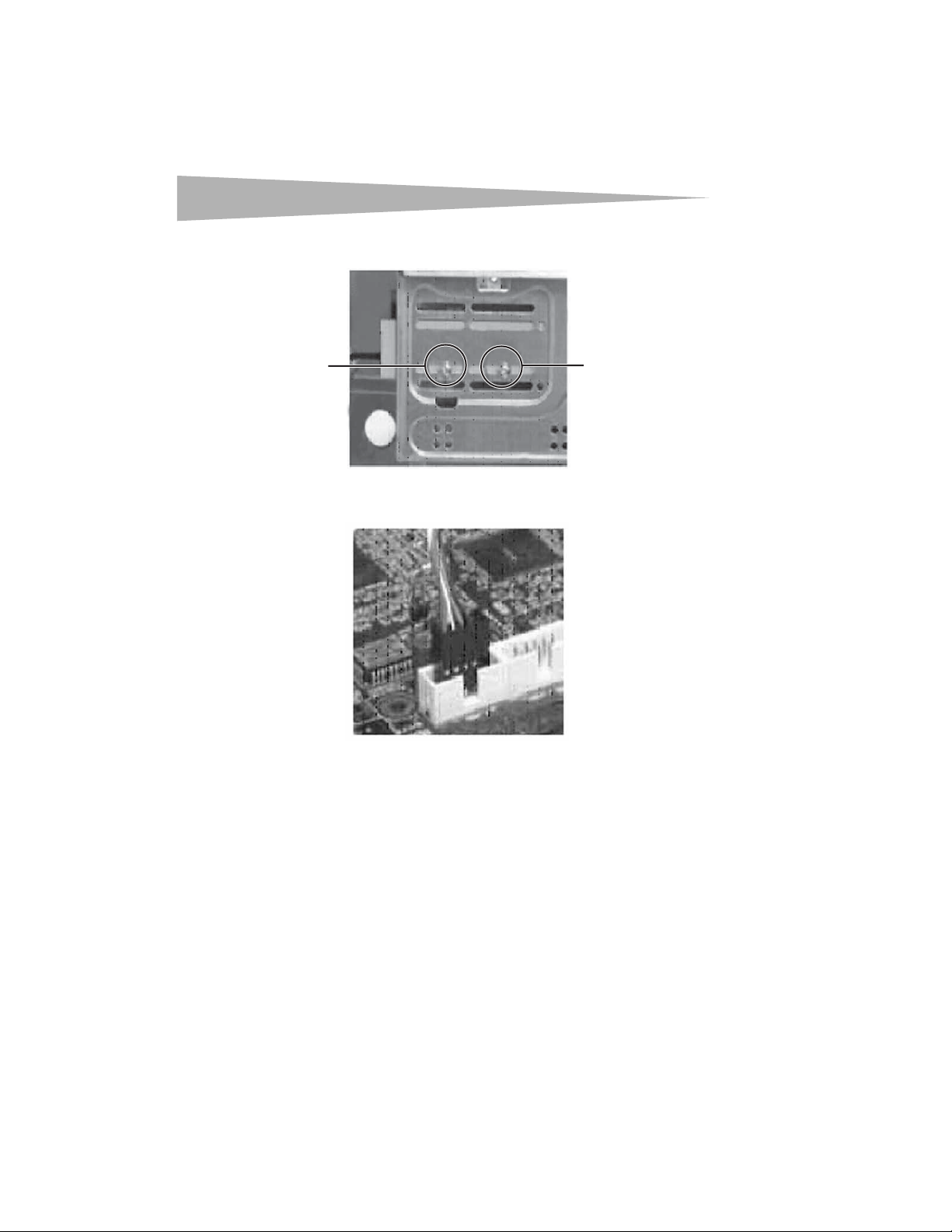
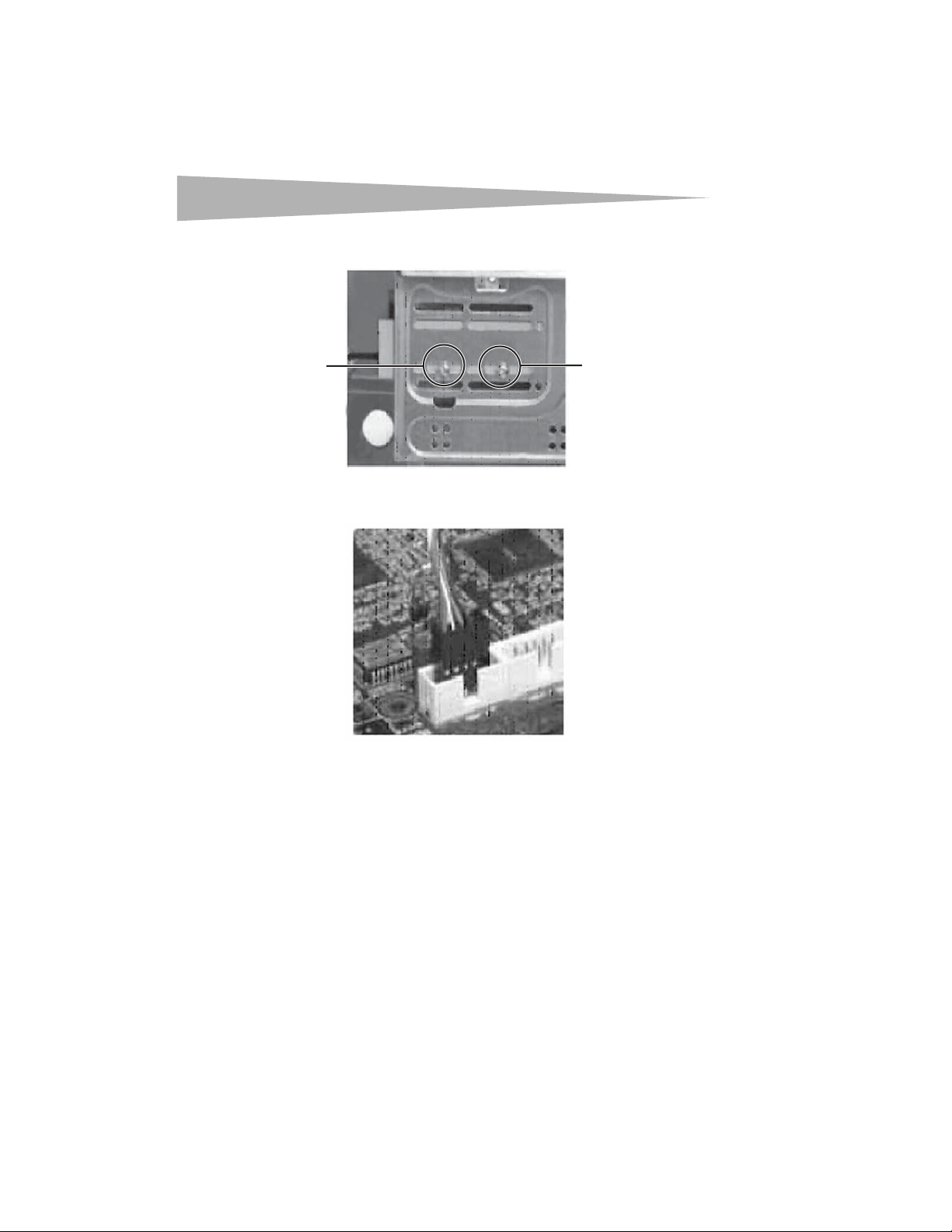
7 Secure your card reader to the drive bay with the four mounting screws (two screws
per side).
Screw
Screw
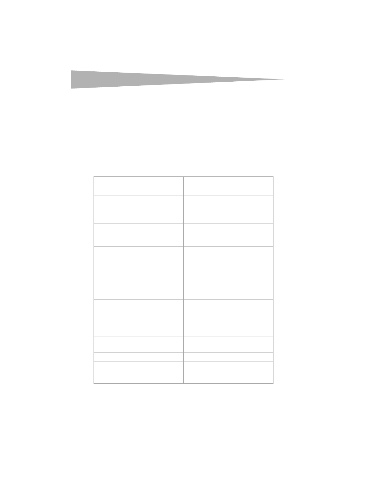
8 Connect your card reader’s USB connector to a compatible USB connector on your
computer’s system board.
9 Make sure that you have removed any tools or loose screws from inside your computer,
then replace your computer’s cover.
10 Reconnect your computer’s power cord, then turn on your computer.
Installing the driver
Windows XP or Windows 2000
Wind ows
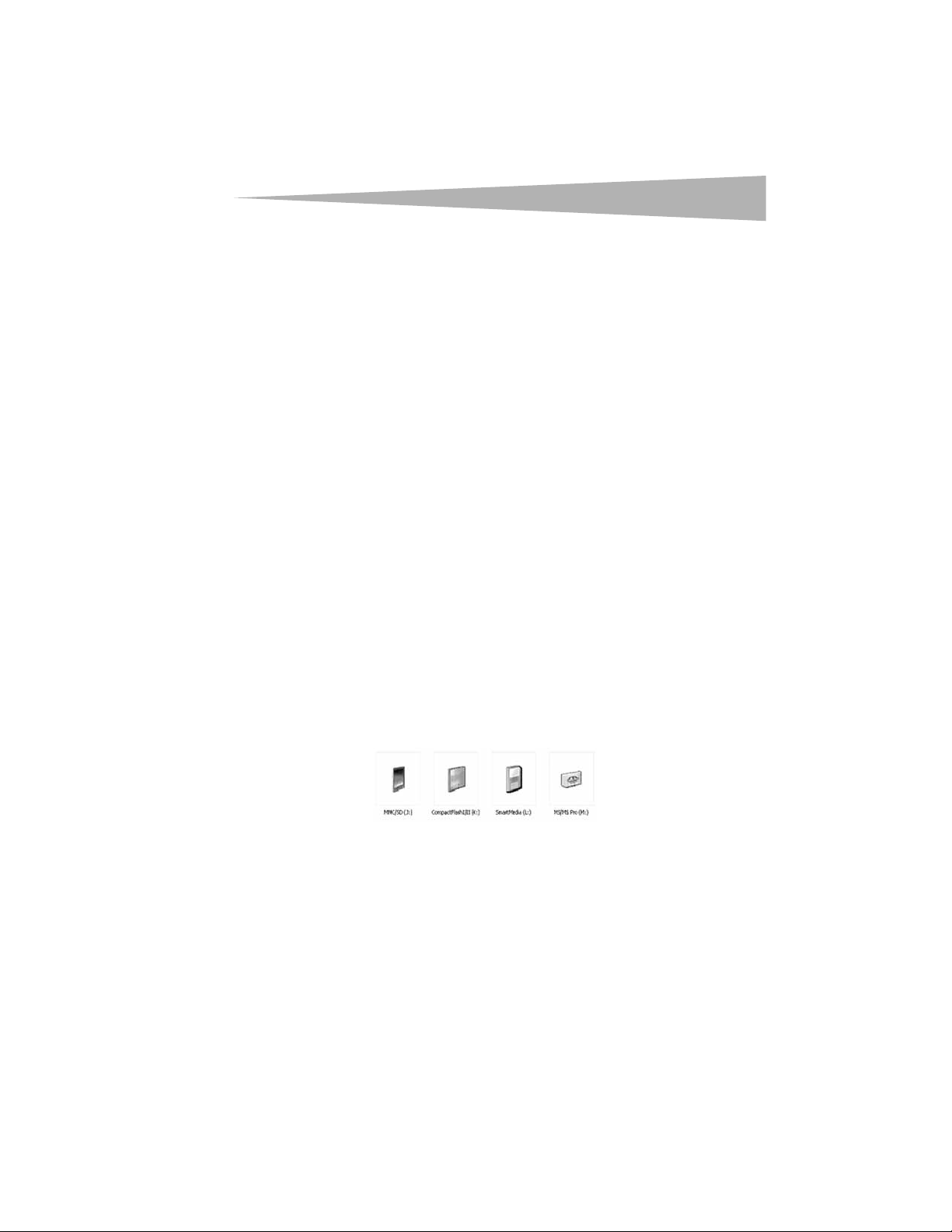
After you install your card reader and turn on your computer, Windows installs the correct
driver, and four new drive icons appear in the My Computer and Windows Explorer windows.
® XP and Windows® 2000 have built-in drivers. You do not need to install a driver.
Note: The T-Flash and the MMC/SD slots share the same drive icon.
Using your card reader
Windows 98SE and Windows ME
To install the driver in Windows® 98SE or Windows® ME:
1 Save all files and close all programs.
2 Insert the utility CD into your CD drive.
3 Open the Driver folder, then open the Windows folder.
4 Double-click on the setup.exe file.
5 Click Next, then follow the on-screen instructions to install the driver.
6 After the driver installation is complete, restart your computer.
Your c ard rea der is rea dy to u se. Ma ke sure that y ou ins ert t he cor rect type card in to the
appropriate slot. For more information about which cards each slot accepts, see
“Front” on page 4.
If you want to customize the card reader drive icons in the Windows Explorer and My
Com puter windows, see “Customizing drive icons” on page 9.
Using your card reader
Customizing drive icons
To make the slots easier to recognize, you can customize the drive icons.
To customize the drive icons:
1 Save all files and close all programs.
2 Insert the utility CD into your CD drive.
3 Open the Driver folder, then double-click on the setup.exe file.
4 Click Next to start the installation, and follow any on-screen instructions.
5 After the installation is complete, restart your computer. Windows
drive icons for the slots instead of the standard Windows drive icons.
When Windows detects a card in a slot, the corresponding drive icon turns from grey to
a color that indicates the card type.
9
® displays the new
Using a media card
To use a media card:
1 Insert a card into the appropriate slot. For more information about which slot to use,
see “Front” on page 4.
2 Open the My Computer or Windows Explorer window, then double-click the drive icon
for the slot you are using.
3 Use normal Windows procedures for opening, copying, pasting, or deleting files and
folders to access files and folders on the inserted card.
10
Specifications
Chipset ALCOR
Supported file formats FAT 12/16/32/NTFS
Five memory slots
Four drive icons
Supported ca rds CF (Type I and Type II), CF Ultra II, Micro Drive,
Indicators Green “card detect” and “data activity”
Interface USB 5-Pin pin housing type that connects to
Operating temperature Operating: 32° ~104°F (0° ~40°C)
Cable length 19.7 inches (50 cm)
Housing 4.02 × 4.65 × 1 inches
Certification FCC Class B, ICES-003
Supported operating systems
Specifications
•CF/MD
•SM/++
• SD/Mini SD/MMC/RS-MMC
•MS-/MS-DUO
•T-Flash
• MMC/SD/T-Flash
• Compact Flash I/II
• Smart Media/++
•MS/MS Pro
Magic Gate, SM, SM ROM, ++, ++ M-series,
SD, SD Ultra II, Mini SD, MMC-I, MMC-II, MMC
4.0, MMC Dual Voltage, RS-MMC, RS-MMC
Dual Voltage, RS-MMC 4.0, T-Flash, MS, MS
Select, MS ROM, MS PRO, MS Magic Gate,
MS-PRO Magic Gate, MS-DUO Magic Gate,
and MS-PRO-DUO
indicator
the system board USB connector
Storage: -4° ~140° F (-20° ~60° C)
102 × 118 × 25.4 mm
RoHS compliant
•Windows® 98SE
•Windows® ME
• Windows® 2000
•Windows® XP

Legal notices
Legal notices
FCC statement
This equipment has been tested and found to comply with the limits for a Class B digital
device, pursuant to Part 15 of the FCC Rules. These limits are designed to provide reasonable
protection against harmful interference in a residential installation. This equipment
generates, uses and can radiate radio frequency energy and, if not installed and used in
accordance with the instructions, may cause harmful interference to radio communications.
However, there is no guarantee that interference will not occur in a particular installation. If
this equipment does cause harmful interference to radio or television reception, which can
be determined by turning the equipment off and on, the user is encouraged to try to correct
the interference by one or more of the following measures:
• Reorient or relocate the receiving antenna.
• Increase the separation between the equipment and receiver.
• Connect the equipment into an outlet on a circuit different from that to which the
receiver is connected.
• Consult the dealer or an experienced radio/TV technician for help.
ICES - Canada's Interference-Causing Equipment Standards This equipment complies with
the applicable technical standards of ICES 003:1997 in accordance with the measurement
procedures specified in CISPR22-96.
Copyright
© 2006 Dynex. DYNEX and the DYNEX logo are trademarks of Best Buy Enterprise Services,
Inc. Other brands and product names are trademarks or registered trademarks of their
respective holders. Specifications and features are subject to change without notice or
obligation.
11

12
Table des matières
Lecteur de carte interne tout-en-un
Dynex DX-CRD12
Table des matières
Introduction ....................................................................................12
Instructions de sécurité importantes ...............................................13
Composants du lecteur de carte ......................................................13
Installation du lecteur de carte........................................................17
Utilisation du lecteur de carte .........................................................20
Spécifications ..................................................................................21
Avis juridiques.................................................................................22
Introduction
Grâce à ses cinq fentes, ce lecteur de carte prend en charge de plus de 25 types de cartes
mémoires et offre les avantages de plusieurs lecteurs de carte. Il est idéal pour une
installation dans une baie d'unité de 3,5 pouces. Ce lecteur de carte accepte les cartes
standard, telles que Secure Digital (SD), Multi Media (MMC), Compact Flash™ (CF), IBM®
Microdrive, Smart Media™ (SM), Memory Stick (MS), Memory Stick pro, la carte d'images
++ et d'autres cartes compatibles de mémoire flash. Ce lecteur de carte accepte également
des cartes flash de petites dimensions sans nécessiter d'adaptateur, telles que les cartes
Mini-SD, RS-MMC, MS-DUO et les mini-cartes T-flash (Micro SD).
Caractéristiques
Caractéristiques du lecteur de carte :
• Cinq fentes pour cartes flash, permettant de prendre en charge jusqu'à 25 types de
cartes mémoires
• Accès direct frontal efficace sur un ordinateur
• Installation aisée dans une baie d'unité de 3,5 pouces
• Conformité avec les spécifications d'interface USB (Bus Série Universel) 2.0
• Conformité avec les spécifications applicables aux périphériques de stockage USB
• Prise en charge des spécifications 8 bits pour RS-MMC 4.0
• Prise en charge de cartes flash de petites dimensions qui exigent généralement un
adaptateur, telles que les cartes mini SD, RS-MMC, T-flash (Micro SD) et MS-Duo.
• Remplacement à chaud et technologie Plug and Play (branchez et utilisez)
• Fentes de carte qui peuvent être utilisées en même temps pour un échange de
données
• Prise en charge de quatre icônes de carte mémoire permettant de reconnaître
facilement le lecteur
• Cadre avant échangeable pour permettre une personnalisation des couleurs

Instructions de sécurité importantes
Instructions de sécurité importantes
Avant de commencer, lire ces instructions et les conserver pour toute référence ultérieure.
• Avant d'installer le lecteur de carte dans l'ordinateur, lire ce guide de l'utilisateur. Dans
certains systèmes d’exploitation, le pilote doit être installé avant d'installer le lecteur
de carte.
• Ne pas faire tomber ni heurter le lecteur de carte.
• Ne pas installer le lecteur de carte dans un endroit qui est soumis à de fortes
vibrations, étant donné que les vibrations peuvent endommager le lecteur de carte.
• Ne pas démonter ni essayer de modifier le lecteur de carte. Le démontage ou la
modification peut annuler la garantie et pourrait endommager le lecteur de carte et
provoquer un incendie ou un choc électrique.
• Ne pas entreposer le lecteur de carte dans un endroit humide. Ne pas laisser de
l'humidité ou des liquides s'écouler dans le lecteur de carte. Les liquides peuvent
endommager le lecteur de carte et provoquer un incendie ou un choc électrique.
• Ne pas insérer d'objets métalliques, tels que des pièces de monnaie ou des trombones,
dans le lecteur de carte.
• Ne pas retirer une carte quand la DEL témoin indique qu'un transfert de données est
en cours. Cela pourrait endommager la carte et occasionner la perte de données
enregistrées sur la carte.
• Le lecteur de carte est conçu pour un usage non-professionnel de l’ordinateur. Il ne
doit pas être utilisé dans un ordinateur requérant une fiabilité exceptionnelle, surtout
si une défaillance ou un fonctionnement défectueux de la carte pourrait mettre en
danger la vie ou la santé, comme dans le cas des équipements aéronautiques, des
systèmes de contrôle de l’énergie atomique, des équipements de régulation de la
circulation, des équipements de transport, de la robotique industrielle, des
équipements de combustion, des appareils de sécurité et des systèmes de survie.
13
Composants du lecteur de carte
Contenu de l’emballage
Vérifier que l'emballage contient :
• 1 lecteur de carte avec un câble USB à 5 broches
• 4 vis de montage (ISO 3f 4 mm)
• 1 cadre avant supplémentaire
•1 CD d'utilitaires
• 1 guide de l’utilisateur

14
Composants du lecteur de carte
Configuration système minimale requise
•PC IBM ou compatible
• Processeur Pentium 133 MHz ou supérieur
•Lecteur de CD
• 2 Mo d’espace sur le disque dur
• Un connecteur USB à 5 broches disponible sur la carte système de l'ordinateur
• Une baie d'unité de 3,5 pouces disponible
•Windows
® 98SE, Windows® ME, Windows® 2000 ou Windows® XP
Avant
Attention : Les cartes doivent être insérées dans la fente correcte et dans le bon sens. Sinon,
la carte et la fente risquent d'être endommagées.
Fente SM/++
Fente SM/++
/++
Fente CF/MD
Caractéristique Description
Remarque : La flèche montre le sens
dans lequel la carte doit être insérée
dans la fente.
Fent e SD /MC C/M ini
SD/RS-MMC
Fente MS/MS-DUO Fente T-Flash
Insérer les cartes mémoires Smart Media ou
les cartes d'images ++ dans cette fente.
Remarque : Insérer une carte d'images ++
dans le côté droit de la fente.
DEL

Composants du lecteur de carte
Caractéristique Description
Fente SD/MMC
Remarque : La flèche montre le sens
dans lequel la carte doit être insérée
dans la fente.
DEL Indique lorsqu'une fente lit ou écrit sur une
Fente CF/MD
Insérer les cartes Secure Digital (SD), Mini SD,
Multi Media (MMC) ou RS-MMC dans cette
fente.
Remarque : La zone de contact en or de la
carte Mini SD doit être tournée vers le haut.
Insérer une carte Mini SD dans le côté gauche
de la fente.
carte.
DEL éteinte – Le lecteur de carte n'est pas
utilisé.
DEL allumée – Une carte est insérée dans
l'une des fentes.
DEL clignotante – Des données sont
transférées entre une carte et le disque dur
ou une autre carte.
Insérer les cartes Compact Flash (type I/II),
IBM Microdrive ou Magicstor dans cette
fente.
15
Remarque : La flèche montre le sens
dans lequel la carte doit être insérée
dans la fente.

16
Fente MS/MS-DUO
Fente T-Flash
Composants du lecteur de carte
Caractéristique Description
Insérer les cartes Memory Stick, MS-Pro or
MS-DUO de Sony dans cette fente.
Remarque : La flèche montre le sens
dans lequel la carte doit être insérée
dans la fente.
Insérer les cartes mémoires Transflash ou
Micro SD dans cette fente. Aucun adaptateur
n'est nécessaire.
Remarque : La fente T-flash et le bus de
signaux sont partagés avec la fente SD/MMC,
ce qui signifie qu'il n'est pas possible
d'utiliser les deux fentes en même temps.
Remarque : La flèche montre le sens
dans lequel la carte doit être insérée
dans la fente.

Installation du lecteur de carte
Installation du lecteur de carte
Remplacement du cadre avant
Pour remplacer le cadre avant :
1 Utiliser un stylet ou un outil de type stylo pour appuyer sur le clip en plastique de
chaque côté du lecteur de carte et retirer l'ancien cadre.
Clip en plastique
2 Enclencher le nouveau cadre en place.
17
Installation du lecteur de carte
Affectation des broches du câble USB
Veiller à ce que le connecteur de la carte système de l'ordinateur soit compatible avec le
connecteur USB du lecteur de carte en comparant le connecteur USB du lecteur de carte avec
le connecteur situé sur la carte système de l'ordinateur.
Connecteur du lecteur de carte
P5
P1
Broche
P5 Blindage Terre
P4 Noir Terre
P3 Vert D+
Couleur du
câble
Fonction

18
Installation du lecteur de carte
Broche
P2 Blanc D–
P1 Rouge VBUS
Couleur du
câble
Connecteur de la carte système
Attention : Une décharge d’électricité statique peut endommager les composants
électroniques. S'assurer d'être correctement relié à la terre avant d'installer le lecteur de
carte. Éteindre l'ordinateur, puis toucher une partie métallique nue de l'ordinateur, telle
que le dos du châssis ou l'alimentation électrique, pour décharger toute électricité
statique.
Pour installer le lecteur de carte :
1 Pour installer le lecteur de carte dans un ordinateur fonctionnant sous Windows 98SE,
installer le pilote avant d'installer le lecteur de carte. Pour plus d’informations,
consulter « Windows 98SE et Windows ME », voir page 20.
2 Veiller à être correctement relié à la terre en touchant une partie métallique nue de
l'ordinateur, telle que le dos du châssis ou l'alimentation électrique.
3 Mettre l’ordinateur hors tension, puis débrancher le cordon d’alimentation.
4 Ouvrir le couvercle du boîtier de l’ordinateur. Pour tous renseignements
complémentaires, se reporter à la documentation livrée avec l'ordinateur.
5 S’assurer que le connecteur de la carte système de l'ordinateur est compatible avec le
connecteur USB du lecteur de carte. Pour plus d’informations, consulter « Affectation
des broches du câble USB », voir page 17.
6 Glisser soigneusement le lecteur de carte dans la baie d'unité vide.
Fonction

Installation du lecteur de carte
7 Fixer le lecteur de carte dans la baie d'unité à l'aide des quatre vis de montage (deux
vis de chaque côté).
19
Vis
Vis
8 Connecter le connecteur USB du lecteur de carte à un connecteur USB compatible sur
la carte système de l'ordinateur.
9 S’assurer que tous les outils et les vis inutilisées ont été enlevés de l’intérieur de
l’ordinateur, puis replacer le couvercle du boîtier.
10 Rebrancher le cordon d’alimentation de l’ordinateur, puis allumer l’ordinateur.
Installation du pilote
Windows XP ou Windows 2000
Wind ows
pilote.
Une fois le lecteur de carte installé et l'ordinateur allumé, Windows installe le pilote correct
et quatre nouvelles icônes d'unité apparaissent dans les fenêtres Pos te de travail et
Explorateur Windows.
® XP et Windows® 2000 ont des pilotes intégrés. Il n'est pas nécessaire d'installer un
Remarque : Les fentes T-Flash et MMC/SD partagent la même icône de lecteur.

20
Windows 98SE et Windows ME
Pour installer le pilote sous Windows® 98SE ou Windows® ME :
1 Enregistrer tous les fichiers et fermer tous les programmes.
2 Insérer le CD d’utilitaires dans le lecteur de CD.
3 Ouvrir le dossier Driver (Pilote), puis ouvrir le dossier Windows.
4 Double-cliquer sur le fichier setup.exe.
5 Cliquer sur Next (Suivant), puis suivre les instructions à l'écran pour installer le pilote.
6 Une fois l'installation du pilote terminée, redémarrer l'ordinateur.
Le lecteur de carte est prêt à l'utilisation. Veiller à insérer le type de carte correct dans
la fente appropriée. Pour plus d’informations sur les cartes acceptées par chaque fente,
voir « Avant », voir page 14.
Pour personnaliser les icônes d'unité du lecteur de carte dans les fenêtres Explorateur
Windows et Poste de travail, voir « Personnalisation des icônes d'unité », voir page 20.
Utilisation du lecteur de carte
Utilisation du lecteur de carte
Personnalisation des icônes d'unité
Pour que les fentes soient plus faciles à reconnaître, il est possible de personnaliser les icônes
d'unité.
Pour personnaliser les icônes d'unité :
1 Enregistrer tous les fichiers et fermer tous les programmes.
2 Insérer le CD d’utilitaires dans le lecteur de CD.
3 Ouvrir le dossier Driver (Pilote), puis double-cliquer sur le fichier setup.exe.
4 Cliquer sur Next (Suivant) pour commencer l'installation, puis suivre les instructions
affichées à l'écran.
5 Une fois l'installation terminée, redémarrer l'ordinateur. Windows
nouvelles icônes d'unité pour les fentes au lieu des icônes d'unité standard sous
Wind ows.
Lorsque le Windows détecte une carte dans une fente, l'icône de lecteur
correspondante passe du gris à une couleur qui indique le type de carte.
® affiche les

Spécifications
Utilisation d'une carte mémoire
Pour utiliser une carte mémoire :
1 Insérer une carte dans la fente appropriée. Pour plus d’informations sur la fente à
utiliser, voir « Avant », voir page 14.
2 Ouvrir la fenêtre Poste de travail ou Explorateur Windows, puis double-cliquer sur
l'icône de lecteur correspondant à la fente utilisée.
3 Utiliser les procédures normales de Windows pour ouvrir, copier, coller ou supprimer
des fichiers et dossiers et accéder aux fichiers et dossiers sur la carte insérée.
Spécifications
Jeu de puces ALCOR
Formats de fichiers compatibles FAT 12/16/32/NTFS
Cinq fentes de mémoire
Quatre icônes d'unité
Cartes compatibles CF (Type I et Type II), CF Ultra II, Micro Drive,
Témoins Témoin vert de « détection de car te » et de «
Interface Connecteur USB à 5 broches, de type boîtier
Température de fonctionnement En fonctionnement : 32 ° ~104 °F (0 ° ~40
Longueur du câble 19,7 pouces (50 cm)
Boîtier 4,02 × 4,65 × 1 pouces
•CF/MD
•SM/++
• SD/Mini SD/MMC/RS-MMC
•MS-/MS-DUO
•T-Flash
• MMC/SD/T-Flash
• Compact Flash I/II
• Smart Media/++
•MS/MS Pro
Magic Gate, SM, SM ROM, ++, ++ M-series,
SD, SD Ultra II, Mini SD, MMC-I, MMC-II, MMC
4.0, MMC Dual Voltage, RS-MMC, RS-MMC
Dual Voltage, RS-MMC 4.0, T-Flash, MS, MS
Select, MS ROM, MS PRO, MS Magic Gate,
MS-PRO Magic Gate, MS-DUO Magic Gate et
MS-PRO-DUO
transfert de données »
de broches, qui se connecte au connecteur
USB de la carte système
°C)
Entreposage : -4 ° ~140 °F (-20 ° ~60 °C)
102 × 118 × 25,4 mm
Conforme à la directive RoHS
21

22
Homologation FCC classe B, ICES-003
Systèmes d’exploitation compatibles
Avis juridiques
Déclaration de la FCC :
Cet équipement a été testé et déclaré conforme aux limitations prévues dans le cadre de la
catégorie B des appareils numériques, définie par l’article 15 du règlement de la FCC. Ces
limites ont été établies pour fournir une protection raisonnable contre les interférences
nocives lors d’une installation résidentielle. Cet équipement génère, utilise et diffuse des
ondes radio et s’il n’est ni installé ni utilisé conformément aux instructions en vigueur, il peut
provoquer des interférences indésirables avec les communications radio. Cependant, nous ne
pouvons pas garantir qu’aucune interférence ne se produira pour une installation
particulière. Si cet équipement produit des inter férences importantes lors de réceptions radio
ou télévisées, qui peuvent être détectées en éteignant puis en rallumant l’appareil, essayer
de corriger l’interférence au moyen de l’une ou de plusieurs des mesures suivantes :
• Réorienter ou déplacer l’antenne réceptrice.
• Augmenter la distance entre l’équipement et le récepteur.
• Brancher l’équipement dans la prise électrique d’un circuit différent de celui auquel le
récepteur est relié.
• Contacter le revendeur ou un technicien radio/télévision qualifié pour toute
assistance.ICES - Réglementation canadienne sur les équipements causant des
interférencesCet appareil est conforme aux normes techniques applicables de ICES
003:1997 selon les procédures de mesure spécifiées dans CISPR22-96.
•Windows® 98SE
•Windows® ME
• Windows® 2000
•Windows® XP
Avis juridiques
Droits d’auteurs
©2006 Dynex. DYNEX et le logo de DYNEX sont des marques de commerce de Best Buy
Enterprise Services, Inc. Les autres noms de marques et de produits sont des marques de
commerce ou des marques de commerce déposées de leurs propriétaires respectifs. Les
caractéristiques et spécifications sont susceptibles d’être modifiées sans préavis.

Contenido
23
Lector de Tarjetas Todo en Uno Interno
Dynex DX-CRD12
Contenido
Introducción ................................................................................... 23
Instrucciones importantes de seguridad......................................... 24
Componentes del lector de tarjetas ................................................ 24
Instalación del lector de tarjetas ..................................................... 28
Uso de su lector de tarjetas ............................................................. 31
Especificaciones .............................................................................. 32
Avisos legales ................................................................................. 33
Introducción
Las cinco ranuras de su lector de tarjetas es compatible con más de 25 tipos de tarjetas de
memoria y provee las ventajas de múltiples lectores de tarjetas. Es ideal para la instalación
en un compartimientouna bahia de unidad de 3.5 pulgadas. Su lector de tarjetas acepta
tarjetas estándar, tal cómo Secure Digital (SD), Multi Media (MMC), Compact FlashMR (CF),
IBM® Microdrive, Smart Media™ (SM), Memory stick (MS), Memory stick pro, ++ picture
card, y otras tarjetas de memoria compatibles. Su lector de tarjetas también acepta tarjetas
flash de tamaño pequeño sin necesidad de usar adaptadores, tal cómo Mini-SD, RS-MMC,
MS-DUO, y las tarjetas T-flash de tamaño pequeño (Micro SD)
Características
Su lector de tarjetas cuenta con:
• Cinco ranuras para tarjetas flash que aceptansoportan hasta 25 tipos de tarjetas de
memoria
• Montaje fácil en un compartimiento de unidaduna bahía de unidad de 3.5 pulgadas
• Se adhiere a la interfaz de la especificación USB (Bus Serial Universal) 2.0
• Se adhiere a la especificación de la clase de dispositivo de almacenamiento masivo
USB
• SoportaCompatibilidad con la especificación RS-MMC 4.0 de 8 bits
• SoportaCompatibilidad con las tarjetas flash de tamaño pequeño que normalmente
requieren un adaptador, tal cómo mini SD, RS-MMC, T-flash (Micro SD) y MS-Duo.
• Capacidad Plug & Play de intercambio durante actividaden caliente
• Ranuras para tarjeta que pueden ser usadas al mismo tiempo para intercambiar
información
• Soporte deCon capacidad para cuatro iconos de tarjetas de memoria para el
reconocimiento fácil de la unidad
• PlacaBisel frontal intercambiable para la personalización del color

24
Instrucciones importantes de seguridad
Instrucciones importantes de seguridad
Antes de comenzar, lea estas instrucciones y guárdelas para referencia futura.
• Antes que instale su lector de tarjetas en su computadora, lea esta guía del usuario. En
algunos sistemas operativos, el controlador debe ser instalado antes que conecte su
lector de tarjetas.
• No deje caer ni golpee su lector de tarjetas.
• No instale su lector de tarjetas en una ubicación que esté expuesta a vibraciones
fuertes ya que la vibración puede dañarlo su lector de tarjetas.
• No desarme nio trate de modificar su lector de tarjetas. El desarme o la modificación
puede anular su garantía y puede dañar elsu lector de tarjetas ocasionando un
incendio o choque eléctrico.
• No guarde su lector de tarjetas en un lugar húmedo.una ubicación húmeda. No
permita que la humedad o líquidos ingresen algoteen dentro de su lector de tarjetas.
Los líquidos pueden dañar elsu lector de tarjetas ocasionando un incendio o choque
eléctrico.
• No inserte objetos metálicos tal cómo monedas o clips de papel en su lector de
tarjetas.
• No saque una tarjeta cuando el indicador LED muestre que se lleva acabo actividad de
datos. Podría dañar la tarjeta y perder información almacenada en la tarjeta.
• Su lector de tarjetas está diseñado para uso general de computadora. No use su lector
de tarjetas en una computadora que requiere confiabilidad excepcional,
especialmente si una falla o mal funcionamiento de su lector de tarjetas puedepueda
poner en riesgo la vida o la salud, tal cómo en equipo aeroespacial, sistema de control
de energía atómica, equipo relacionado con tráfico, equipo de transporte, robots
industriales, equipo de combustión, equipos de seguridad y sistemas de
mantenimiento de vida.
Componentes del lector de tarjetas
Contenido de la caja
Asegúrese de que recibió lo siguiente:
• 1 lector de tarjetas con un cable USB de 5 pinesterminales
• 4 tornillos de montaje (ISO 3f 4 mm)
• 1 biselplaca frontal adicional
•1 CD de utilidades
•1 guía del usuario

Componentes del lector de tarjetas
Requisitos mínimos de sistema
• PC compatible con IBM
• Procesador Pentium de 133 MHz o mejor
• Unidad de CD
• 2 MB de espacio de disco duro
• Un conector USB de 5 pinesterminales disponible en la tarjeta del sistema de la
computadora
• Una bahía de unidadcompartimiento de unidad de 3.5 pulgadas disponible
•Windows
® 98SE, Windows® ME, Windows® 2000, o Windows® XP
Vista Frontal
Cuidado: Las tarjetas se deben insertar en la ranura correcta y en la dirección correcta. De
otra forma podría dañar la tarjeta o la ranura.
25
Ranura para SM/++
Ranura para SD/
Ranura para
SM/++
/++
Ranura para
CF/MD
Función Descripción
MCC/Mini SD/
RS-MMC
Ranura para MS/
MS-DUO
Indicador LED
Ranura para
T-Fl ash
Inserte tarjetas de memoria Smart Media o
tarjetas de fotografías ++ en esta ranura.
Nota: Inserte una tarjeta de fotografías ++
en el lado derecho de la ranura.
Nota: La flecha indica la dirección en la
que debe insertar la tarjeta en la
ranura .
26
Función Descripción
Ranura SD/MMC
Nota: La flecha indica la dirección en la
que debe insertar la tarjeta en la
ranura .
Indicador LED Indica cuando la ranura esta leyendo o
Ranura para CF/MD
Componentes del lector de tarjetas
Inserte tarjetas Secure Digital (SD), Mini SD,
Multi Media (MMC), o RS-MMC en esta
ranura.
Nota: El área de contacto dorada de la
tarjeta Mini SD debe ver hacia arriba. Inserte
una tarjeta Mini SD en el lado izquierdo de la
ranura.
grabando la tarjeta.
LED apagado – Su lector de tarjetas no se
está usando.
LED encendido – Una tarjeta está inser tada
en una de las ranuras.
LED parpadeando – Se están transfiriendo
datos hacia o desde la tarjeta y el disco duro u
otra tarjeta.
Inserte tarjetas Compact Flash (tipo I/II), IBM
Microdrive o Magicstor en esta ranura.
Nota: La flecha indica la dirección en la
que debe insertar la tarjeta en la
ranura .

Componentes del lector de tarjetas
Función Descripción
Ranura para MS/MS-DUO
Nota: La flecha indica la dirección en la
que debe insertar la tarjeta en la
ranura .
Ranura para T-Flash
27
Inserte tarjetas de memoria Sony memory
sticks o MS-Pro o MS-DUO en esta ranura.
Inserte una tarjetas de memoria Transflash o
Micro SD en esta ranura. No se requiere un
adaptador.
Nota: La ranura para T-flash y el bus de
señales se comparten con la ranura para SD/
MMC lo que significa que no puede usar
ambas al mismo tiempo.
Nota: La flecha indica la dirección en la
que debe insertar la tarjeta en la
ranura .

28
Instalación del lector de tarjetas
Instalación del lector de tarjetas
Cambio del bisel la placa frontal
Para cambiar el bisella placa frontal:
1 Use un estiletestylus o una herramienta parecida a un lápiz para presionar el clip de
plástico a cada lado de su lector de tarjetas para extraer el bisel antiguoremover la
placa antigua.
Clip de plástico
2 Instale el nuevo bisella placa nueva en su lugar.
Instalación de su lector de tarjetas
Asignación de pinesterminales en el cable USB
Verifique que el conector de la tarjeta del sistema de su computadora es compatible con el
conector USB de su lector de tarjetas comparando los dos.
Conector del lector de tarjetas
P5
P1
TerminalPin Color del cable Función
P5 Blindaje GND (Tierra)
P4 Negro GND (Tierra)
P3 Verde D+

Instalación del lector de tarjetas
TerminalPin Color del cable Función
P2 Blanco D–
P1 Rojo VBUS
Conector de la tarjeta del sistema
Cuidado: La descarga electrostática (electricidad estática) puede dañar los componentes
electrónicos. Verifique que usted estáse encuentra conectado a tierra correctamente antes
de instalar su lector de tarjetas. Apague su computadora, luego toque una parte metálica
expuesta de su computadora, tal cómo la parte posterior del chasis o la fuente de
alimentación, para descargar cualquier electricidad estática.
Para instalar su lector de tarjetas:
1 Si está instalando su lector de tarjetas en una computadora con Windows 98SE, instale
el controlador antes de instalar su lector de tarjetas. Para obtener más información,
consulterefiérase a “Windows 98SE y Windows ME” en la página 31.
2 Verifique que usted estáse encuentra conectado a tierra correctamente tocando una
parte metálica expuesta de su computadora tal cómo la parte posterior del chasis o la
fuente de alimentación.
3 Apague su computadora y desconecte el cable de alimentación.
4 Abra la caja de la computadora. Para obtener más información, consulterefiérase a la
documentación que vino con su computadora.
5 Verifique que el conector de la tarjeta del sistema de su computadora es compatible
con el conector USB de su lector de tarjetas. Para obtener más información,
consulterefiérase a “Asignación de pinesterminales en el cable USB” en la página 28.
6 Deslice cuidadosamente su lector de tarjetas en el compartimiento de la unidadla
bahía de la unidad vacía.
29
30
Instalación del lector de tarjetas
7 Asegure su lector de tarjetas en el compartimiento de la unidadla bahía de la unidad
con los cuatro tornillos de montaje (dos tornillos por lado).
Tornillo
Tor ni llo
8 Conecte el conector USB de su lector de tarjetas a un conector USB compatible en la
tarjeta del sistema de su computadora.
9 Verifique que ha extraídoremovido todas las herramientas o tornillos sueltos del
interior adentro de su computadora y vuelva a colocar la cubierta de su computadora.
10 Reconecte el cable de alimentación de su computadora y enciéndala.
Instalación del controlador
Windows XP o Windows 2000
Wind ows
un controlador.
Después de instalar su lector de tarjetas y encender su computadora, Windows instalar el
controlador correcto y cuatro iconos de unidad nuevos aparecerán en las ventanas de Mi PC y
del Explorador de Windows.
® XP y Windows® 2000 ya tienen los controladores integrados. No necesita instalar
Nota: Las ranuras de T-Flash y de MMC/SD comparten el mismo icono de unidad.

Uso de su lector de tarjetas
Windows 98SE y Windows ME
Para instalar el controlador en Windows® 98SE o Windows® ME:
1 Guarde todos os archivos y cierre todos los programas.
2 Inserte el CD de utilidades en su unidad de CD.
3 Abra la carpeta Driver (Controlador) y luego la carpeta Windows.
4 Haga doble clic en el archivo setup.exe.
5 Haga clic en Next (Siguiente) y siga las instrucciones de pantalla para instalar el
controlador.
6 Después que concluyade que se termine la instalación del controlador, reinicie su
computadora.
Su lector de tarjetas está listo para ser usado. Verifique que insertainserte el tipo de
tarjeta correcto en la ranura respectiva. Para obtener más información acerca de que
tarjetas se aceptan en cada ranura, consulterefiérase a “Vista Frontal” en la página25.
Si desea personalizar los iconos de unidad del lector de tarjetas en las ventanas del
Explorador de Windows y de Mi PC, consulterefiérase a “Personalización de los iconos de
unidad” en la página 31.
Uso de su lector de tarjetas
Personalización de los iconos de unidad
Para hacer las ranuras más fáciles de reconocer, puede personalizar los iconos de unidad.
Para personalizar los iconos de unidad:
1 Guarde todos los archivos y cierre todos los programas.
2 Inserte el CD de utilidades en su unidad de CD.
3 Abra la carpeta Driver (Controlador) y haga doble clic en el archivo setup.exe.
4 Haga clic en Next (Siguiente) para comenzar la instalación y siga las instrucciones de
la pantalla.
5 Después que haya concluidode que se termine la instalación, reinicie su computadora.
Wind ows
estándar de Windows.
Cuando Windows detecta una tarjeta en una ranura, el icono de unidad
correspondiente cambiará de color gris a un color que indica el tipo de tarjeta.
® mostrará los iconos de unidad nuevos en lugar de los iconos de unidad
31
32
Uso de una tarjeta de memoria
Para usar una tarjeta de memoria:
1 Inserte una tarjeta en la ranura apropiada. Para obtener más información acerca de
que tarjetas se deben usar, consulterefiérase a “Vista Frontal” en la página25.
2 Abra la ventana de Mi PC o el Explorador de Windows y haga doble clic en el icono de
unidad de la tarjeta que está usando.
3 Use los procedimientos normales de Windows para abrir, copiar, pegar o borrar
archivos y carpetas para acceder a los archivos y carpetas en la tarjeta insertada.
Especificaciones
Conjunto de chips ALCOR
Formatos de archivos compatibles FAT 12/16/32/NTFS
Cinco ranuras de memoria
Cuatro iconos de unidad
Tarjetas compatiblessoportadas CF (Tipo I y Tipo II), CF Ultra II, Micro Drive,
Indicadores Indicador verde de “detección de tarjeta” y
Interfaz Tipo de envolventealojamiento USB de 5
Temperatura en operación Operación: 32 ~ 104 °F (0 ~ 40 °C)
Longitud del cable 19.7 pulgadas (50 cm)
AlojamientoEnvolvente 4.02 × 4.65 × 1 pulgadas
Especificaciones
•CF/MD
•SM/++
• SD/Mini SD/MMC/RS-MMC
•MS-/MS-DUO
•T-Flash
• MMC/SD/T-Flash
• Compact Flash I/II
• Smart Media/++
•MS/MS Pro
Magic Gate, SM, SM ROM, ++, ++ Serie M,
SD, SD Ultra II, Mini SD, MMC-I, MMC-II, MMC
4.0, MMC de Doble Voltaje, RS-MMC,
RS-MMC de Doble Voltaje, RS-MMC 4.0,
T-Flash, MS, MS Select, MS ROM, MS PRO, MS
Magic Gate, MS-PRO Magic Gate, MS-DUO
Magic Gate y MS-PRO-DUO
“actividad de datos”
pinesterminales que se conecta al conector
USB de la tarjeta del sistema
Almacenamiento: -4 ~140 °F (-20 ~ 60 °C)
102 × 118 × 25.4 mm
Cumple con la especificación RoHS

Avisos legales
Certificación FCC Clase B, ICES-003
Sistemas operativos compatibles:
Avisos legales
Declaración de la FCC
Este equipo se haha sido sometido a pruebas y se ha determinado que satisface los límites
establecidos para clasificarlo cómo dispositivo digital de Clase B de acuerdo con la Parte 15
del reglamento FCC. Estos límites se han establecido para proporcionar una protección
razonable contra interferencias perjudiciales en una instalación residencial. Este equipo
genera, utiliza y puede irradiar energía de radiofrecuencia y, si no es instalado y utilizado de
acuerdo a las instrucciones, puede causar interferencias perjudiciales en las comunicaciones
de radio. Sin embargo, no se garantiza que no ocurrirá interferencia en una instalación
particular. Si el equipo causa interferencias perjudiciales en la recepción de la señal de radio o
televisión, lo cual puede comprobarse encendiéndolo y apagándolo alternativamente, se
recomienda al usuario corregir la interferencia mediante uno de los siguientes
procedimientos:
• Cambie la orientación o la ubicación de la antena receptora.
• Aumente la distancia entre el equipo y el receptor.
• Conecte el equipo a un tomacorriente de un circuito distinto de aquél al que está
conectado el receptor.
• Solicite consejo al distribuidor o a un técnico experto en radio/TV para obtener ayuda.
ICES – Estándares Canadienses de Equipos que Ocasionan Interferencia Este equipo cumple
con los estándares técnicos aplicables del ICES 003:1997 conforme a los procedimientos de
medición especificados en CISPR22-96.
•Windows® 98SE
•Windows® ME
• Windows® 2000
•Windows® XP
33
Derechos de Reproducción
© 2006 Dynex. DYNEX y el logotipo de DYNEX son marcas comerciales de Best Buy Enterprise
Services, Inc. Otras marcas y nombres de productos son marcas comerciales o marcas
registradas de sus respectivos dueños. Las especificaciones y características están sujetas a
cambio sin aviso previo u obligación.

34
Avisos legales

Avisos legales
35

www.dynexproducts.com (800) 305-2204
Distributed by Best Buy Purchasing, LLC
7601 Penn Ave. South, Richfield, MN 55423 U.S.A.
Distribué par Best Buy Purchasing, LLC
7601 Penn Ave. South, Richfield, MN 55423 É.-U.
Distribuido por Best Buy Purchasing, LLC
7601 Penn Ave. South, Richfield, MN 55423 U.S.A.
 Loading...