

Page 1
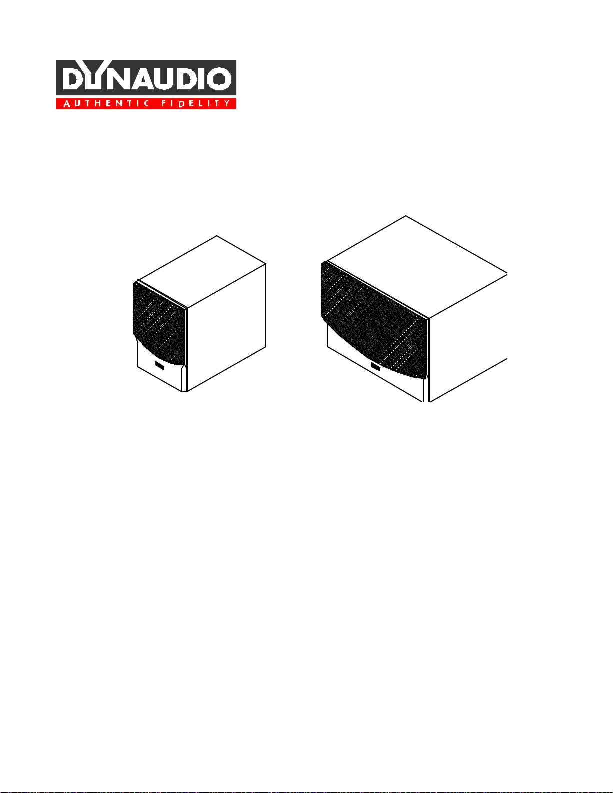
Audience SUB-20A
Owner's Manual
and Safety Instructions
Audience SUB-30A
Page 2

Page 3

Installation
Important Safety Instructions
Read these instructions before any connection to the apparatus.
Please keep these instructions in a convenient place.
CAUTION
To avoid electric shock, do not open the subwoofer.
There are no user-serviceable parts inside.
Do not operate this apparatus near water.
Do not install near any heat sources such as radiators, heat registers, fireplaces, stoves, or
other items (including large amplifiers) that produce heat.
Do not cover the apparatus. Keep it ventilated.
Power connection
Do not defeat the safety purpose of the grounding-type plug. A grounding-type plug has
two blades and a third grounding prong. The third prong is provided for safety. If the
provided plug does not fit into the wall outlet, consult an electrician for replacement of the
obsolete outlet.
Protect the power cord from being stepped on or pinched, particularly at plugs,
convenience receptacles, and the point where they exit from the apparatus.
Unplug this apparatus during lightning storms or when unused for long periods of time.
Attachments
Only use attachments/accessories specified by the manufacturer.
Servicing
Refer all servicing to qualified service personnel. Servicing is required when the apparatus
has been damaged in a way such as power supply cord or plug is damaged, liquid has been
spilled or objects have fallen into the apparatus, the apparatus has been exposed to rain or
moisture, has been dropped, or does not operate normally.
Maintenance
To prevent fire or shock hazard, clean only with a damp cloth. Never use cleansers or
chemicals.
Page 4
Important Safety Instructions
Please note that excessive listening at high sound pressure levels may cause permanent
hearing damage.
Warning
This equipment can
produce sound pressure
levels in excess of 90 dB(A)
Unpacking
Page 5

Contents
ABOUT THIS PRODUCT 6
OPERATION AND LOCATION OF CONTROLS 7
Level 8
Crossover frequency 8
Phase / Phase switch 8
Input terminal Right and Left / Input terminal Mono 9
Output switch / Output terminal Right and Left 9
Utility Link terminal Input/Output 10
Standby 10
Subsonic filter 10
Protection circuit 11
Power switch 11
AC inlet 11
Voltage switch 11
Fuse-drawer 11
INSTALLATION 12
Multi-channel sound system 13
POSITIONING 14
TROUBLESHOOTING 15
No sound 15
Distorted sound 15
SPECIFICATIONS 16
Page 6

The Dynaudio subwoofer provides quality low frequency output to extend the frequency
range of the speaker system, and offers enhanced low bass when used as a dedicated
subwoofer in an A/V or surround system.
The SUB-20A is fitted with a 24 cm (9.5 inch) woofer, and the SUB-30A is fitted with a 30
cm (12 inch) woofer. To achieve maximum sound output, both models’ woofer is mounted in a
port tuned enclosure.
With Dynaudio's Utility Link, it is possible to combine two subwoofers in a multi-channel
audio system. With three inputs on each subwoofer, up to six channels may be summed into
one (mono) subwoofer channel.
The dimensions of the Audience SUB-30A will make it possible to use it as a CTV-stand. An
optional Audience Center speaker fits perfectly on top of the Audience SUB-30A, thereby
minimizing the space normally taken by a subwoofer in a living room.
Both subwoofers are selfpowered designs (actively amplified). The amplifiers power supply
can be used with various voltages, 115/230 V ~, and frequencies, 60/50 Hz. A voltage selector
switch on the back panel of the subwoofer may be positioned according to the required voltage
in your area. The setting is pre-set by the manufacturer prior to shipping. Do not try to alter
the voltage setting, as doing so will result in a blown fuse. Wrong settings may result in
damaged electronics.
Page 7

Operation and Location of Controls
1 Level
2 Crossover frequency
3 Phase
4 Phase switch
5 Output filter switch
6 Output terminal Right and Left
7 Input terminal Right and Left
8 Input terminal Mono
9 Utility IN/OUT terminal (bi-directional)
10 Voltage selector switch
11 Fuse-drawer
12 Power switch
13 AC inlet
Page 8

The level control knob allows for subwoofer output matching to the system. To obtain a
neutral sound balance it is important that the subwoofer level is set correctly. To do this,
adjust the control up and down until a natural sounding bass level is obtained in the system.
Readjustment is recommended if any crossover and/or phase settings are changed on the
subwoofer.
With the variable low-pass filter, it is possible to adjust the subwoofer to accurately
compliment the main speakers and obtain optimum performance. Adjusting the frequency
between 60 Hz and 120 Hz allows for the best transition from the subwoofer to the point
where the main speakers roll-off.
The Audience SUB is equipped with advanced phase adjustment circuit, enabling for proper
phase alignment with the audio system.
The phase control knob enables variable phase settings between 0° to 180° or 180° to 360°
depending on the slide switch position.
Using the control knob and slide switch, adjust the phase until the most coherent and
quantitative bass is heard at the normal listening position.
Optimum adjustment can be checked by temporarily sliding the switch to the opposite
position. If correct phase adjustments are achieved, this will create a preceived reduction in
Page 9

Input terminal Right and Left / Input terminal Mono
This subwoofer provides 3 low level inputs: Left, Right, and Mono. These inputs can be used
in any combination. Signals from all 3 inputs are summed and fed to the subwoofer.
Do not connect any of these inputs to high level signals such as power amplifier speaker
outputs!
If a SUB OUT terminal (or equivalent) is not present on the pre-amp/processor, then connect
the subwoofer via PRE OUT to <IN R> and <IN L>.
Output switch / Output terminal Right and Left
The output terminals are intended for use when a separate power amplifier or integrated
amplifier with separate inputs is available.
Using this output enables the removal of frequencies below 80 Hz from the main speakers by
setting the switch to < Lowcut 80 Hz>.
With the output switch in the <Flat> position, the input terminals are connected directly to
the output terminals. With the output switch in the <Lowcut 80 Hz> position, the signal
passes through an active second order (12 dB/octave, f
selection cuts frequencies below 80 Hz to the main speakers, thereby reducing potential
distortion.
= 80 Hz) high-pass filter. This
-3dB
Page 10

If two Dynaudio subwoofers are to be used, they may be connected via the Utility Link. With
this link a total of six input terminals is possible. This feature is intended for use with a multichannel surround sound system.
In discreet surround sound systems such as AC-3, MPEG- 2, and DTS, all 5 channels can be
full range. With the Dynaudio Utility Link, the two subwoofers sum all these channels into
one mono subwoofer channel, reproduced by the two subwoofers.
Connect the two subwoofers via the <UTILITY In/Out>.
Connect all outputs from the surround sound system to <IN Mono>, <IN R> and <IN L> on
both subwoofers arbitrarily. It is not necessary to use all inputs. More on this setup is
mentioned later in the manual.
The subwoofer has an internal standby function. The standby will be activated when there is
no input signal to the subwoofer for 10 minutes.
When powering on and off, the mute circuit will mute both the subwoofer itself and the
output terminals. This ensures that no noise can be heard in the subwoofer and in the main
speakers (if using the outputs).
Due to a very low standby power consumption, the subwoofer power switch may be left on
continuously. If unused for several days, it is recommended to switch off the main power or
disconnect the device from the main outlet.
When using the 80 Hz low frequency cut-off for the main speakers, do not switch off the
power for the subwoofer while the sound system is playing. If this is done, the signal to the
output terminal will be muted. After a few minutes music should become present in the main
speakers, but very attenuated. This is not a fault, but merely a result of signal passing through
the electronics when no power is supplied. If listening is desired while the subwoofer is
switched off, set the output switch to position <Flat>.
The subwoofer has an active second order (12 dB/octave below 20 Hz) subsonic filter to
prevent rumble, speaker distortion, or overload situations caused by signals that cannot be
heard.
Page 11

Protection circuit
To prevent thermal overload, the mute circuit will be activated at 65°C (149° F) and will be
automatically deactivated when the temperature drops to 50°C (122° F). Under normal
conditions this should rarely occur.
Power switch
Switches the power on and off. When the subwoofer is on, the power switch lights up.
AC inlet
This is a grounding-type plug.
If the sound system has an AC convenient outlet, connect the power supply cord from the
subwoofer to this device. Otherwise connect it to an AC wall outlet.
Voltage switch
The voltage switch is positioned according to area voltage requirements. It has been pre-set
prior to shipping from the factory.
CAUTION
Do not try to alter the voltage setting, as doing so will result in a blown fuse. A wrong setting
may result in damaged electronics.
Fuse-drawer
The main fuse for the subwoofer is located in the Fuse-drawer.
CAUTION
For continued protection against risk of fire, replace only with same type of fuse.
Fuse rating: 115 V: 1.6 A / 125 V Slow-blow
230 V: 0.8 A / 250 V Slow-blow
Page 12

CAUTION Switch off all equipment before any installation!
If the sound system has a SUB OUT terminal (or equivalent), connect the subwoofer to this
terminal.
(Fig. A)
If the system does not have a SUB OUT terminal (or equivalent), connect the subwoofer
input to the PRE OUT terminal on the equipment (Fig. B).
(Fig. B)
The subwoofer can also be used together with small main speakers, as in subwoofer/satellite
systems.
When used in a subwoofer/satellite system together with a preamplifier and a power amplifier
(Fig. B), the signal from the output terminals of the subwoofer should be connected to the
amplifier input. Using the output terminals on the subwoofer enables the removal of low
Page 13

frequency content from the main speakers. This is accomplished by changing the Output Filter
switch from <Flat> to <Lowcut 80 Hz>.
Multi-channel sound system
In multi-channel sound systems such as AC-3, AMPEG-2, and DTS, the dedicated subwoofer
(LFE; Low Frequency Effects) output from the surround decoder should be used (Fig. A).
If small loudspeakers are used throughout the surround setup, it is preferable to feed bass
signals from all five surround channels, and the subwoofer channel, to the subwoofer(s). If
multiple Dynaudio subwoofers are to be used, connect them with the Utility Link <Utility
In/Out>. Connect the Utility Link between two subwoofers as shown below. Example: two
subwoofers will act as one big subwoofer with a total of six inputs, three on each. It is very
important that all controls and switches are set in the same position on both subwoofers.
Use the three inputs <Left>, <Right>, and <Mono> on the first subwoofer for the respective
Left Front, Right Front, and Center channels. On the second subwoofer use the Left, Right, and
Mono input for the Left Rear, Right Rear, and Subwoofer channels (Fig. C).
(Fig. C)
Page 14

Useful hints:
Best results are usually achieved with the subwoofer aimed towards the listening area,
positioned between the main loudspeakers and near the wall. Both the floor and the walls will
enhance the sound output. If the subwoofer is placed in a corner, maximum sound output will
be achieved, but the quality of the stereo image may be sacrificed. If center placement is
impossible, position the subwoofer towards the right, as the drums in an orchestra are usually
located at the right rear of the sound stage.
Do not cover the back plate, otherwise the subwoofer amplifier will become too hot and the
protection circuit will activate. Do not place the subwoofer with the back plate in direct
sunlight.
Since the port is placed on the back side of the subwoofer, we recommend a clearance of at
least 5 centimeters (2 inches) to the wall; preferably more.
The subwoofer may be positioned anywhere in the listening room, and with a little patience,
some time, and a broad variety of music material or movie soundtracks, an optimum location
will be found.
Page 15

Troubleshooting
No sound
If there is no sound from the subwoofer, please check the following:
• Is the <Power switch> on?
• Is the <Level> positioned at minimum?
• Is your cable connected to output instead of input?
• Is the back plate very hot? Wait until it cools off.
• Is the audio system connected correctly? If there is any doubt, turn the power off. Connect
a CD-player or tuner directly to the subwoofer <IN R> and <IN L>. Before doing so, make
sure to turn down the level on the subwoofer. When all is connected and the power is
turned on, slowly turn up the level. If the subwoofer is playing with a direct source, the
fault will most likely be elsewhere in the audio system.
Distorted sound
If the sound from the subwoofer is distorted, or if other problems exist, please consult the
dealer that sold the product. Do not try to repair the subwoofer yourself. Any unauthorized
tampering will invalidate the manufacturer’s warranty.
Page 16

Audience SUB-20A
Frequency response 25 Hz-150 Hz (room depending)
Crossover frequency
Variable low-pass 60 Hz-120 Hz
High-pass output 80 Hz, 12 dB per octave
Sensitivity 50 mV
Max. amplifier power output 90 W
Max. SPL 110 dB (typical in-room)
Nominal impedance
Mono, Left, Right input 47 K ohms
Driver 24 cm (9.5 inch)
Dimensions H, W, D 430 mm, 276 mm, 455 mm
Weight 14 kilograms (30.8 lbs.)
Power consumption
Standby 10 W
Max. 150 W
(16.9”, 10.9”, 17.9”)
Audience SUB-30A
Frequency response 23 Hz-150 Hz (room depending)
Crossover frequency
Variable low-pass 60 Hz-120 Hz
High-pass output 80 Hz, 12 dB per octave
Sensitivity 50 mV
Max. amplifier power output 90 W
Max. SPL 115 dB (typical in-room)
Nominal impedance
Mono, Left, Right input 47 K ohms
Driver 30 cm (12 inch)
Dimensions H, W, D 430 mm, 570 mm, 400 mm
(16.9”, 22.4”, 15.7”)
Weight 24 kilograms (52.8 lbs.)
Power consumption
Standby 10 W
Max. 150 W
Page 17

Page 18

Copyright 1997, DYNAUDIO A/S, Denmark
DK-8660 Skanderborg
All Rights Reserved.
Printed in Denmark
DYNAUDIO A/S
Sverigesvej 15
Page 19

Fax +45 86 52 31 16
 Loading...