

Page 1
\
Instron Dynatup
8250 Drop Weight Impact Tester
M14-13655-EN
Operating Instructions
Page 2

Electromagnetic Compatibility
Where applicable, this equipment is designed to comply with International
Electromagnetic Compatibility (EMC) standards.
To ensure reproduction of this EMC performance, connect this equipment to a low
impedance ground connection. Typical suitable connections are a ground spike or the
steel frame of a building.
Proprietary Rights Notice
This document and the information that it contains are the property of Instron
Corporation. Rights to duplicate or otherwise copy this document and rights to disclose
the document and the information that it contains to others and the right to use the
information contained therein may be acquired only by written permission signed by a
duly authorized officer of Instron Corporation.
© Copyright 1999 Instron Corporation
Revision A
Page 3

General Safety PrecautionsGeneral Safety Precautions
Materials testing systems are potentially hazardous.
Materials testing involves inherent hazards from high forces, rapid motions and stored
energy. You must be aware of all moving and operating components which are
potentially hazardous, particularly the moving crosshead or pendulum in an impact
testing system.
Carefully read all relevant manuals and observe all Warnings and Cautions. The term
Warning is used where a hazard may lead to injury or death. The term Caution is used
where a hazard may lead to damage to equipment or to loss of data.
Ensure that the test set-up and the actual test you will be using on materials, assemblies
or structures constitutes no hazard to yourself or others. Make full use of all mechanical
and electronic limits features. These are supplied for your safety to enable you to prevent
movement of the actuator piston or the moving crosshead beyond desired regions of
operation.
The following pages detail various general warnings that you must heed at all times while
using materials testing equipment. You will find more specific Warnings and Cautions in
the text whenever a potential hazard exists.
Preliminary Pages
Your best safety precautions are to gain a thorough understanding of the equipment by
reading your instruction manuals and to always use good judgment.
iii
Page 4

Preliminary Pages M14-13655-EN
Warning
Disconnect the electrical power supply before removing the covers to
electrical equipment.
Disconnect equipment from the electrical power supply before removing any electrical
safety covers or replacing fuses. Do not reconnect the power source while the covers are
removed. Refit covers as soon as possible.
Disconnect power supplies before removing the covers to rotating
machinery.
Disconnect equipment from all power supplies before removing any cover that gives
access to rotating machinery. Do not reconnect any power supply while the covers are
removed unless you are specifically instructed to do so in the manual. If the equipment
needs to be operated to perform maintenance tasks with the covers removed, ensure that
all loose clothing, long hair, etc. is tied back. Refit covers as soon as possible.
Shut off the supply of compressed gas and discharge residual gas
pressure before you disconnect any compressed gas coupling.
Do not release gas connections without first disconnecting the gas supply and discharging
any residual pressure to zero.
Use protective shields or screens if any possibility exists of a hazard
from the failure of a specimen, assembly or structure under test.
Use protective shields whenever a risk of injury to operators and observers exists from
the failure of a test specimen, assembly or structure, particularly where explosive
disintegration may occur. Due to the wide range of specimen materials, assemblies or
structures that may be tested, any hazard resulting from the failure of a test specimen,
assembly or structure is entirely the responsibility of the owner and the user of the
equipment.
Protect electrical cables from damage and inadvertent disconnection.
Protect all electrical cables, particularly transducer cables, from damage. Never route
cables across the floor without protection, nor suspend cables overhead under excessive
strain. Use padding to avoid chafing where cables are routed around corners or through
wall openings.
Wear protective clothing when handling equipment at extremes of
temperature.
Materials testing is often carried out at non-ambient temperatures using ovens, furnaces
or cryogenic chambers. Extreme temperature means an operating temperature exceeding
60 °C (140 °F) or below 0 °C (32 °F). You must use protective clothing, such as gloves,
when handling equipment at these temperatures. Display a warning notice concerning
low or high temperature operation whenever temperature control equipment is in use.
You should note that the hazard from extreme temperature can extend beyond the
immediate area of the test.
iv
Page 5

Warning
Installation or removal of a specimen, assembly or structure involves working inside the
hazard area between the grips or fixtures. Keep clear of clamping devices and pinch
points at all times. Keep clear of the hazard area between the grips or fixtures during
crosshead or pendulum movement.
The robot in an automated testing system presents a hazard because its movements are
hard to predict. The robot can go instantly from a waiting state to high speed operation in
several axes of motion. During system operation, keep away from the operating envelope
of the robot. De-activate the robot before entering the envelope for any purpose, such as
reloading the specimen magazine.
Preliminary Pages
Take care when installing or removing a specimen, assembly or
structure.
Keep clear of the operating envelope of a robotic device unless the
device is de-activated.
v
Page 6

Preliminary Pages M14-13655-EN
WarningWarning
At no time should the machine be operated with any of the safety devicesAt no time should the machine be operated with any of the safety devices
by-passed or malfunctioning.by-passed or malfunctioning.
1. Keep entire body, especially hands, arms and head out of the path of the falling
weight and tup at all times.
2. Only one operator should operate the machine at any given time.
3. Install the safety "H" bar supplied to ensure weight cannot drop whenever weight is
raised and work is being done on system. The safety "H" bar clips to the guide
columns.
4. Perform regular maintenance.
5. Never use the 50 lb. (22.7 kg) or heavier weight set when operating at velocities
above 14.5 ft/s (4.42 m/s).
6. Do not leave tools, spare parts or debris inside the safety enclosure when operating
the impact machine.
7. Do not handle the guide columns. They are easily soiled, which can seriously effect
impact test results.
8. Do not strike non-deformable objects with instrumented tups. If the tup strikes the Tgrooved baseplate, specimen support fixture or a non-deformable specimen, the tup
will likely be damaged.
9. Frequently check the crosshead weight retainer knobs or screws for tightness. They
should be securely tightened before performing impact tests. If these bolts are loose,
the crosshead can bind on the guide columns.
10. Always unplug the power cord when servicing or repairing the Model 8250.
11. Frequently check the hoist cable for damage.
12. When the optional pneumatic assist is installed, frequently check that the large
springs used to accelerate the crosshead are securely screwed to the rods that hold
them.
13. Always use the shock absorbers when pneumatically assisting the crosshead.
14. To prevent potential damage to the crosshead, make sure that the shock set installed
matches the weight set attached to the crosshead. This can be quickly verified by
matching the background color on the sticker attached to the shock with the color
coded dot located on the weight plates.
vi
Page 7

Preliminary Pages
Table of Contents
ChapterChapter PagePage
Introduction 1-1
Introduction.......................................................................................................................1-2
About this Manual .............................................................................................................1-4
Product Support.................................................................................................................1-5
Installed Safety Features....................................................................................................1-6
Specifications 2-1
Specifications....................................................................................................................2-2
Technical Data Sheets.......................................................................................................2-3
Energy and Velocity Tables...............................................................................................2-5
Installation 3-1
Preparing the Site..............................................................................................................3-2
Uncrating the Machine .....................................................................................................3-4
Securing the Model 8250 in Place....................................................................................3-5
Connecting Utilities and Initial Set-up................................................................................3-6
Installing Specimen Support Fixtures .................................................................................3-8
Installing the Tup................................................................................................................3-9
Initial Machine Operation and Checkout .......................................................................3-10
Function of Controls 4-1
Control Pendent ................................................................................................................4-2
Ancillary Machine Controls ...............................................................................................4-4
Preparation for Use 5-1
Adjusting the Velocity Detector .........................................................................................5-2
Adjusting the Stop Blocks and Shock Absorbers................................................................5-4
Installing the Crosshead Weights.......................................................................................5-6
Operation 6-1
Performing a Test...............................................................................................................6-2
vii
Page 8

Preliminary Pages M14-13655-EN
Maintenance and Troubleshooting 7-1
Scheduled Maintenance ..................................................................................................7-2
Troubleshooting.................................................................................................................7-5
Glossary
viii
Page 9

Preliminary Pages
List of Figures
FigureFigure PagePage
Figure 1-1. Dynatup 8250 Drop Tower ........................................................................ 1-3
Figure 3-1. Foundation Layout.................................................................................... 3-2
Figure 3-2. Uncrating .................................................................................................. 3-4
Figure 3-3. Motor Enclosure ........................................................................................ 3-7
Figure 4-1. Control Pendent........................................................................................ 4-2
Figure 4-1. Motor Enclosure ........................................................................................ 4-4
Figure 5-1. Velocity Detector Flag .............................................................................. 5-2
Figure 5-2. Velocity Detector and Flag ...................................................................... 5-3
Figure 5-3. Shock Absorber and Stop Block Setup ..................................................... 5-4
Figure 5-3. Installing the Add-on Weights .................................................................. 5-6
Figure 7-1. Lubrication Points...................................................................................... 7-4
Figure 7-2. Hoist Hub and Pinch Roller Assembly........................................................ 7-6
ix
Page 10

Preliminary Pages M14-13655-EN
x
Page 11

Introduction
Outline
Chapter 1
Introduction
• Introduction.....................................................................................................1-2
• About this Manual...........................................................................................1-4
• Product Support ..............................................................................................1-5
• Installed Safety Features................................................................ ..................1-6
1-1
Page 12

Introduction M14-13655-EN
Introduction
The Model 8250 drop weight impact test machine is used to test the impact
characteristics of an extensive variety of materials and components over a wide range of
impact velocities. Data from these tests can then be used in the evaluation of material or
component performance.
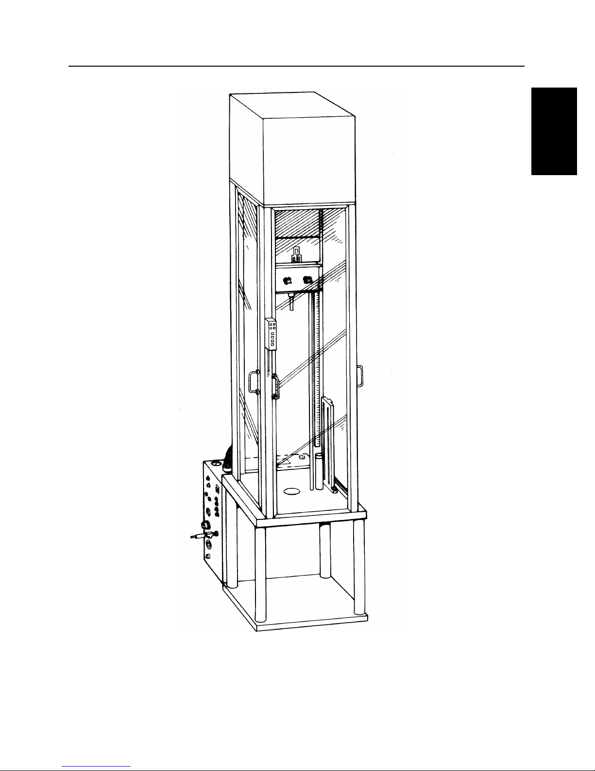
The Model 8250 drop weight impact test machine consists of the frame, two guide
columns, hoist motor, drop-weight mechanism, control pendant, and accessories. Various
weights are available, providing the ability to reach many impact energy ranges. A tup
secured to the lower crosshead provides the load data for the attached data acquisition
system. A photo-detector/flag system provides velocity information.
Figure 1-1 shows the Dynatup 8250 Drop Tower.
Data Acquisition
Data can be acquired with the Instron Dynatup Model 930-I data acquisition system or
other general-purpose data systems. The data acquisition software runs on a personal
computer connected to the Model 8250. Test parameters, test setup information, test
results and statistics are available from the software program. Further information on data
systems can be obtained from Instron Dynatup.
Modes of Operation
The Model 8250 operates in either manual or automatic modes, and can be supplied with
an optional pneumatically assisted crosshead for high impact velocities.
Fixturing is available to conduct tests on manufactured specimens (Izod, Charpy),
components, sheet specimens (plaques, discs, film) and extruded structural shapes (pipes,
channels), to the following standards, as well as to numerous non-standard specifications:
• ASTM D-3763, Plastic Sheet Penetration
• ASTM E-23, Charpy and Izod
• ASTM D-256, Charpy and Izod
• BOEING BMS-256, Composites Penetration/Damage
• NASA ST-1, Composites Damage
• ASTM D-2444, Plastic Pipe
• BOEING 7260, Composites Damage
• MCDONNELL DOUGLAS MDC-J1938A
1-2
Page 13
Introduction
Introduction
Specimens up to six inches wide (15.24 cm) are tested above the upper baseplate and
between the guide columns. Larger specimens are tested below the upper baseplate of
the machine.
Figure 1-1. Dynatup 8250 Drop Tower
1-3
Page 14

About this Manual M14-13655-EN
About this Manual
This manual provides a basic understanding of the 8250 machine and its operation. It
contains specifications, installation instructions, descriptions of the machine controls,
information for preparation and use, and basic maintenance and troubleshooting
information.
1-4
Page 15

Introduction
Product Support
If you encounter problems with your machine, or to order accessories or replacement
parts, contact Instron service using the information below:
• In the United States: 1-800-473-7838
• In Canada: 1-800-461-9123
• In all other regions: contact your nearest Instron Office.
Product Support
1-5
Page 16

Installed Safety Features M14-13655-EN
Installed Safety Features
Several features have been incorporated into the Model 8250 to insure operator safety.
Read this section carefully before installing or using your machine.
• Each door is made of tempered safety glass, letting you view the tests without the
danger of flying debris or specimens. The doors have safety interlocks to prevent
machine operation when any of the doors are open.
• The latch hook is designed to positively engage the crosshead. The more weight or
force applied to the hook, the more it closes.
• In the pneumatic mode, a steel rod, called a shear pin, holds the latch and crosshead
assemblies in a fixed position against compressed springs. The safety system ensures
the shear pin is correctly seated before operation.
• In the event of a power loss or a loss of air pressure, the system automatically shuts
down. Air pressure is monitored at all times. The system can not operate if pressure
falls below 20 psi (140 kPa).
• A cable tension switch and hoist height-limiting switch ensures correct operation of
the latch assembly.
• Overpressure relief valves prevent accidental damage to the machine if excessive air
pressure is applied.
1-6
Page 17

Specifications
Outline
Chapter 2Chapter 2
Specifications
• Specifications..................................................................................................2-2
• Technical Data Sheets .....................................................................................2-3
• Energy and Velociy Table ...............................................................................2-5
2-1
Page 18

Specifications M14-13655-EN
Specifications
Impact Velocity:
Gravity
(GRAV) mode 2.0 to 12.7 ft/sec
(1,440 to 9,144 in/min;
.61 to 3.87 m/sec;
3,658 to 23,225 cm/min)
Pneumatic (PNEU) mode 12.7 to 44 ft/sec
(9,144 to 3l,680 in/min;
3.87 to 13.41 m/s
23,225 to 80,467 cm/min)
Drop Weight:
5.5, 10, 25, 50, 75, 100 lbs.
(2.5, 4.5, 11.3, 22.7, 34.0, 45.3kg)
Impact Energy:
Gravity (GRAV) mode 0.5 to 223 ft-lb. (.67 to 302 Joules)
Pneumatic (PNEU) mode 14.0 to 326 ft-lb. (19.0 to 442 Joules)
Overall Dimensions:
Height 107.06 inches (272cm)
Width 23.0 inches (58.4cm)
Depth 29.3 inches (74.4cm)
Power Requirements:
Standard 120V, 60 Hz, 15 AMPS
Optional 220V-240V, 60 Hz, 10 AMPS
220V-240V, 50 Hz, 10 AMPS
100V, 50 Hz, 20 AMPS
Air Requirements:
Pressure 85-95 psi (585 - 650 kPa)
Flow
2-2
1.0 SCFM (28 L/min at atmospheric
pressure)
Page 19
Specifications
Technical Data Sheets
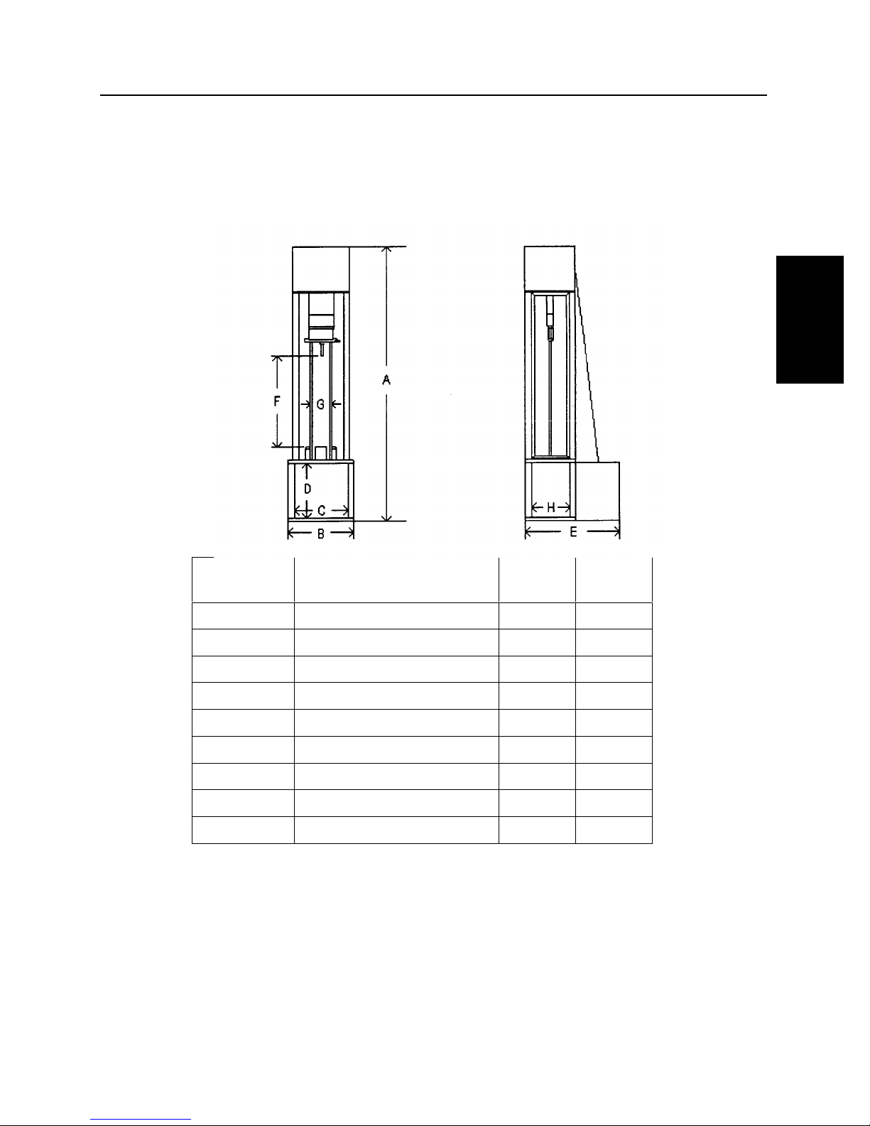
Model 8250HV
Technical Data Sheets
Dimension Description English
(inches)
A Overall Height 107 272
B Total Width 23 58.5
C Max. Component Width 19 48
D Max. Component Height 22 56
E Depth of Drop Tower 20 51
F Depth of Motor Assembly 9.5 24
G Max. Vertical Drop Height 46* 117*
H Inner Guide Rod Clearance 6 15
I Max. Component Depth 14 35.5
Metric
(cm)
* Values dependent upon specimen tup selection and specimen thickness.
Overall system weight: 1300 lbs (588 kg)
Power requirement: 100V – 240V, @ 50-60 Hz, 20 Amps
Air requirement: 0.3 cfm (8.5 lpm) @ 90 psi (6.21 bars)
2-3
Page 20
Technical Data Sheets M14-13655-EN
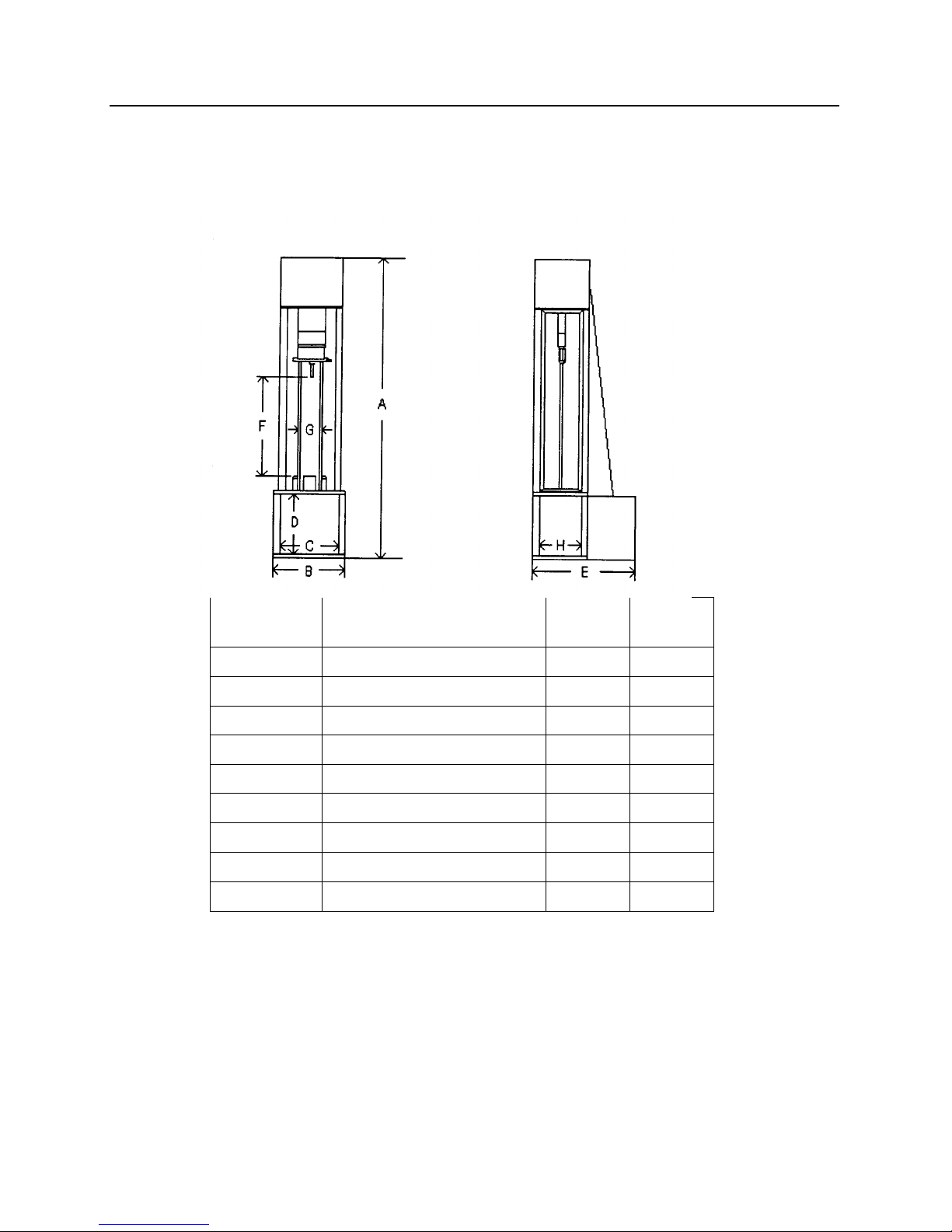
Model 8250NP
Dimension Description English
(inches)
A Overall Height 107 272
B Total Width 23 58.5
C Max. Component Width 19 48
D Max. Component Height 22 56
E Depth of Drop Tower 20 51
F Depth of Motor Assembly 9.5 24
G Vertical Drop Height 46* 117*
H Inner Guide Rod Clearance 6 15
I Max. Component Depth 14 35.5
Metric
(cm)
* Values dependent upon specimen tup selection and specimen thickness.
Overall system weight: 1300 lbs (588 kg)
Power requirement: 100V – 240V, @ 50-60 Hz, 20 Amps
Air requirement: 0.3 cfm (8.5 lpm) @ 90 psi (6.21 bars)
2-4
Page 21
Specifications
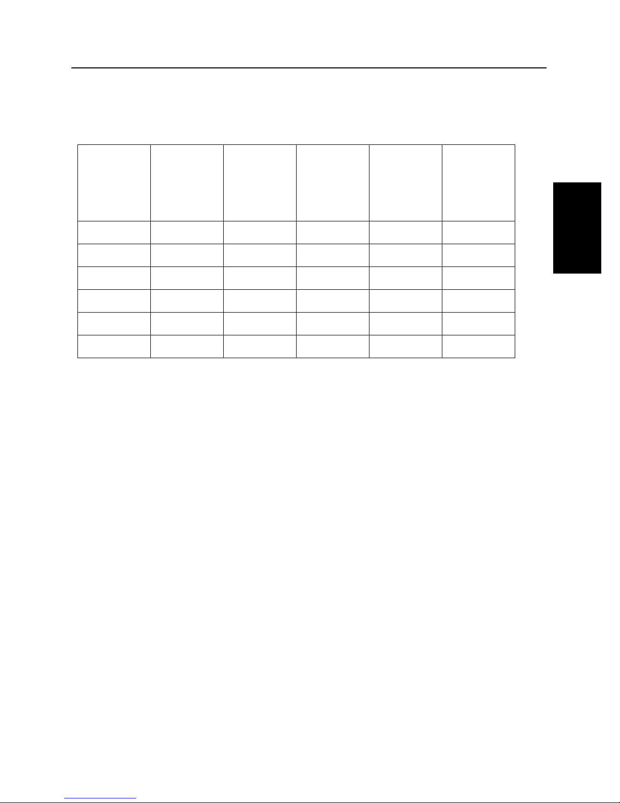
Energy and Velocity Tables
Model 8250HV
Energy and Velocity Tables
Crosshead
Weight
lbs (kg)
5.5 (2.5) 46 (117) 15.7 (4.8) 44.6 (13.6) 21 (28.5) 170 (230)
10 (4.5) 45 (114) 15.5 (4.7) 35.8 (10.9) 37.3 (50.5) 199 (270)
25 (11.3) 43 (109) 15.2 (4.6) 28.1 (8.5) 89.6 (121.5) 306 (415)
50 (22.7) 40 (102) 14.6 (4.4) 23.4 (7.1) 165.5 (224) 425 (576)
75 (34.0) 40 (102) 14.6 (4.4) 20.5 (6.2) 248 (336) 489 (663)
100 (45.4) 40 (102) 14.6 (4.4) 19.7 (6) 331 (448) 602 (816)
Max. Drop
Height*
Inches (cm)
Max.
Freefall
Velocity
Ft/sec (m/s)
Max.
Pneumatic
Assist
Velocity
Ft/sec (m/s)
Max.
Freefall
Impact
Energy
Ft-lbs (J)
Max.
Pneumatic
Impact
Energy
Ft-lbs (J)
* All values are approximate and based on using model 8902 tup. Values will change
depending upon tup selection, test geometry and specimen thickness. Contact InstronDynatup for values pertaining to other testing specifications.
Available specimen support fixtures for specifications:
• ASTM D-3763
• ASTM E-23
• ASTM D-256 Charpy
• ASTM D-256 IZOD
• Boeing BMS-256 Composites Penetration/Damage Fixture
• NASA ST-1 Composites Damage Fixture
• ASTM D-2444 Plastic Pipe Fixture
• Boeing 7620 Composites Damage Fixture
• McDonnell Douglas J11938A Fixture
• Custom Component Fixturing
2-5
Page 22

Energy and Velocity Tables M14-13655-EN
Model 8250NP
Crosshead
Weight
lbs (kg)
Max. Drop
Height*
Inches (cm)
Max.
Freefall
Velocity
Ft/sec (m/s)
Max.
Freefall
Impact
Energy
Ft-lbs (J)
5.5 (2.5) 46 (117) 15.7 (4.8) 21.0 (28.5)
10 (4.5) 45 (114) 15.5 (4.7) 37.3 (50.5)
25 (11.3) 43 (109) 15.2 (4.6) 89.6 (121.5)
50 (22.7) 40 (102) 14.6 (4.4) 165.5 (224)
75 (34.0) 40 (102) 14.6 (4.4) 248 (336)
100 (45.4) 40 (102) 14.6 (4.4) 331 (448)
* All values are approximate and based on using model 8902 tup. Values will change
depending upon tup selection, test geometry and specimen thickness. Contact InstronDynatup for values pertaining to other testing specifications.
Available specimen support fixtures for specifications:
• ASTM D-3763
2-6
• ASTM E-23
• ASTM D-256 Charpy
• ASTM D-256 IZOD
• Boeing BMS-256 Composites Penetration/Damage Fixture
• NASA ST-1 Composites Damage Fixture
• ASTM D-2444 Plastic Pipe Fixture
• Boeing 7620 Composites Damage Fixture
• McDonnell Douglas J11938A Fixture
• Custom Component Fixturing
Page 23

Installation
Outline
Chapter 3
Installation
• Preparing the Site............................................................................................3-2
• Uncrating the Machine ....................................................................................3-4
• Securing the Model 8250 in Place....................................................................3-5
• Connecting Utilities and Initial Set-up.............................................................3-6
• Installing Specimen Support Fixtures ..............................................................3-8
• Installing the Tup ............................................................................................3-9
• Initial Machine Operation and Checkout........................................................ 3-10
3-1
Page 24
Preparing the Site M14-13655-EN
Preparing the Site
Machine Placement
When choosing where to place the machine, consider that the Model 8250 will shake the
surrounding area. The machine should not be placed near delicate instruments.
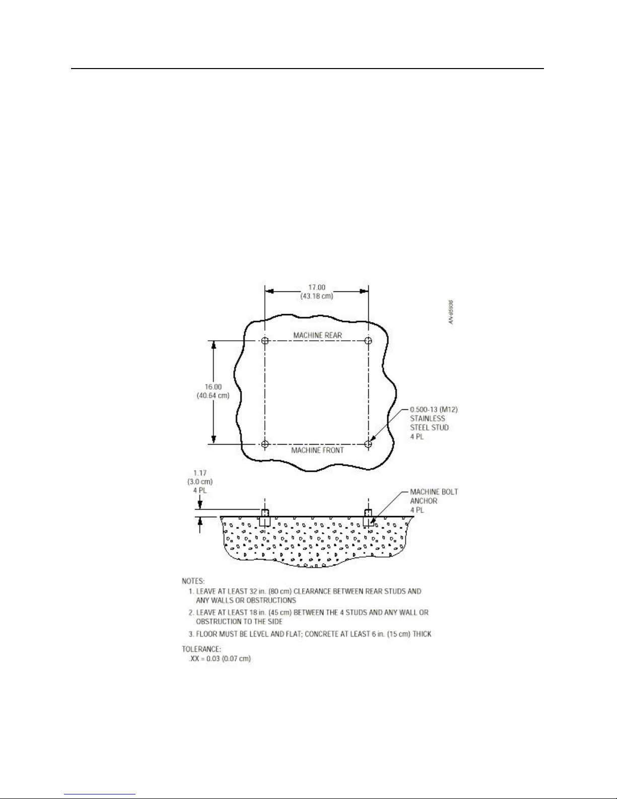
To minimize the effect on the surrounding area, the machine must be bolted in place.
There should be at least 32 inches (80cm) clearance between the rear studs and any wall
or obstructions, and 18 inches (45cm) between the studs and any obstructions to the side.
Figure 3-1 illustrates proper machine placement.
Figure 3-1. Foundation Layout
For correct operation and reliable results, the machine must be level and mounted directly
to the foundation. Do not use any rubber pads, shims, or vibration isolators between the
machine and the foundation. If the foundation is not level, shims with machine grout can
be used. The foundation must contact the entire surface of the machine base.
3-2
Page 25

Installation
Air and Electrical Requirements
The Model 8250 requires a compressed air supply of 85-95 psi (580-650 kPa). The
volume of air used is less than 1.0 SCFM (28 L/min at atmospheric pressure). A male
1/4 inch pipe thread fitting and a barbed fitting are provided for connecting the air supply.
The electrical power required is dependent on the specification given at the time of the
order. Available configurations are:
120Vac 60Hz 15A
100Vac 50Hz 20A
220Vac 50Hz 10A
220Vac 60Hz 10A
If you are unsure of the configuration, either contact Instron Dynatup or remove the back
panel to the rear motor enclosure to expose a label listing the required voltage.
Preparing the Site
3-3
Page 26
Uncrating the Machine M14-13655-EN
Uncrating the Machine
The Model 8250 impact test machine weighs about 400kg (900 lb) and is packed face
down in the crate. Use the following instructions to safely uncrate and stand the machine
up in preparation for final positioning.
CautionCaution
Do not use safety enclosure doors, door handles or the top sheet metalDo not use safety enclosure doors, door handles or the top sheet metal
enclosure to move the machine. Use only the machine frame for tiltingenclosure to move the machine. Use only the machine frame for tilting
and lifting.and lifting.
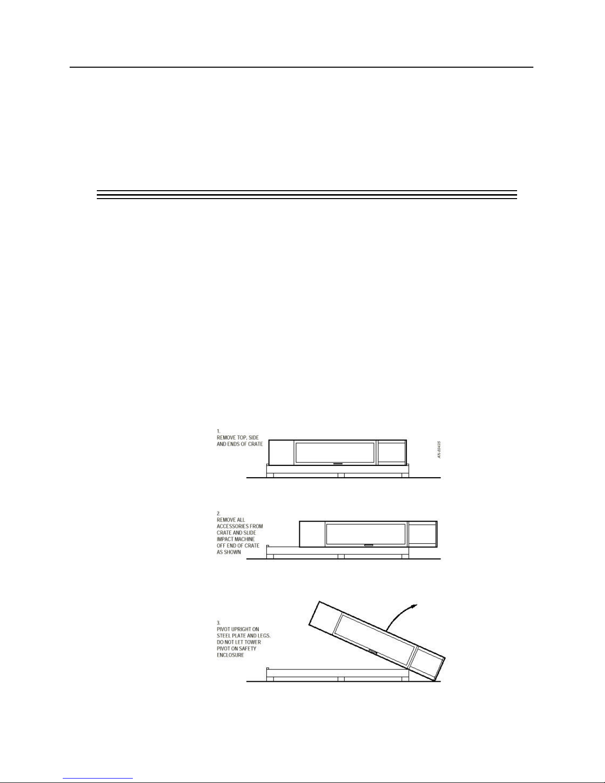
1. Remove the top and side panels of the crate and the plastic sheeting covering the
machine.
2.
Move the pallet with the Model 8250 still banded in place as close to the final
position as possible. Once uncrated, the machine is difficult to move.
3.
Lift the Model 8250 and slide the base off the end of the crate. Lifting the base
of the machine will require a forklift or hoist. As a lift point, use a sling around
the 2 inch (5cm) diameter table legs.
4.
With the table legs and lower table base plate protruding off the end of the crate,
tilt the machine upright. Note the pivot point in Figure 3-2. Do not let the tower
pivot on the safety enclosure.
3-4
Figure 3-2. Uncrating
Page 27

Installation
Securing the Model 8250 in Place
When you are ready to secure the Model 8250 in place, move the machine onto the
foundation and bolt it to the floor with 1/2-13 (M12) stainless steel hardware. If
necessary, use machine grout and shims to level the Model 8250. The entire baseplate
must contact the foundation.
WarningWarning
Install the “H” bar to prevent the crosshead from falling before workingInstall the “H” bar to prevent the crosshead from falling before working
within the safety enclosurewithin the safety enclosure
The model 8250 is supplied with a safety "H" bar for the protection of the user. The "H"
bar clips to the guide columns and prevents the crosshead from falling. Use caution when
working in or around the model 8250 machine. Before working within the safety
enclosure, lift the crosshead beyond the height of the "H" bar and securely install the "H"
bar on the guide columns.
Securing the Model 8250 in Place
3-5
Page 28

Connecting Utilities and Initial Set-up M14-13655-EN
Connecting Utilities and Initial Set-up
Follow these steps to set up and connect the Model 8250 machine:
1.
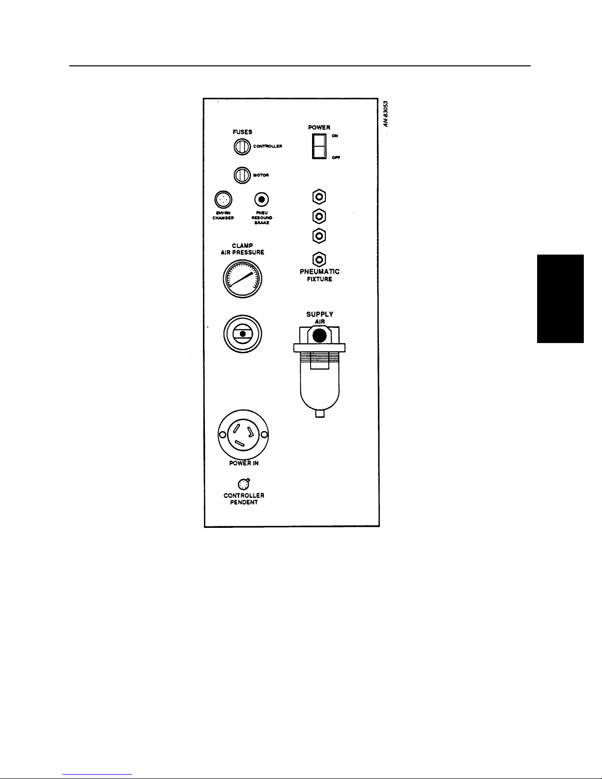
Connect a compressed air line to the fitting labeled SUPPLY AIR on the motor
enclosure. See Figure 3-3. Both a 1/4 inch (6mm) pipe thread and barbed fittings are
provided. With the barbed fitting, always use a hose clamp to lock the hose onto the
barbs.
2.
Connect the electrical supply to the connector labeled POWER IN.
3.
Reverse the safety enclosure handle on the front door.
4.
If you purchased a pneumatic clamp with the system, route the hose assembly under
the back panel of the safety enclosure and connect the fittings to the four male
connectors labeled PNEUMATIC FIXTURE on the motor enclosure. To connect
the fittings, depress the metal tabs and push the assembly over the connectors. You
can hear an audible click when the fittings lock in place.
5.
Route the cables that connect the tup and detector to the Dynatup data system under
the back panel of the safety enclosure. Refer to the section on Tup Installation .
6.
Connect the short (3 ft./ 1m) tup lead to the long (20 ft./6.5m) tup cable and secure
the connectors in place with the clamp on the right rear corner post.
7.
The hand-held control pendent is connected to the Model 8250 by a 10 ft. (3m) cable
with connectors on both ends. Connect one end of the cable to the connector labeled
CONTROLLER PENDENT on the motor enclosure (see Fig. 3-3), and the other end
to the pendent. Be sure to align the connectors properly and push straight in – do not
twist them.
8.
Turn the power on.
9.
Close the safety enclosure doors. The yellow ARM button on the control pendent
illuminates. If the light does not illuminate, refer to Chapter 7, Troubleshooting, or
call Instron Dynatup.
3-6
Page 29
Connecting Utilities and Initial Set-up
Installation
Figure 3-3. Motor Enclosure
3-7
Page 30

Installing Specimen Support Fixtures M14-13655-EN
Installing Specimen Support Fixtures
You must bolt the specimen support fixtures (anvils) either:
• directly to the baseplate of the Model 8250, or
• to a T-grooved baseplate which, in turn, is bolted to the Model 8250 baseplate.
Refer to the following procedures for more information.
Direct-Bolted Fixtures
To install specimen support fixtures that do not require a T-groove baseplate:
1. Remove the T-groove baseplate, if installed.
2. Position the specimen support fixture on the Model 8250 baseplate between the
crosshead guide columns and bolt in place using four 3/8-16 inch (3/8 inch screws,
16 threads to the inch) socket head cap screws.
3. Verify that the tup and crosshead cannot hit any portion of the fixture. This may
require adjusting the height of the stop blocks or shock absorbers. See Chapter 5 for
more information on adjusting stop blocks and shock absorbers.
4. If the fixture is a pneumatic clamp, route the control hose under the back safety
enclosure door and connect it to the fittings on the side of the rear motor enclosure.
Refer to the section on Utility Connections and Initial Set-up. Also, make sure that
the crosshead and tup do not touch the raised clamp plate when the crosshead is on
the stop blocks or shock absorber snubbers.
T-groove Baseplate Fixtures
To install specimen support fixtures with a T-groove baseplate:
1. Bolt the T-groove baseplate in position between the crosshead guide columns, using
four 3/8-16 inch (3/8 inch screws, 16 threads to the inch) socket head cap screws.
2. Loosen the T-nut bolts on the specimen support fixtures and align the T-nuts with the
T-groove baseplate slots. Slide the fixture onto the T-groove.
3. Position the fixture and verify that the tup and crosshead cannot hit any portion of the
fixture. This may require adjusting the height of the stop blocks or shock absorbers.
Refer to the section called Adjusting the Stop Blocks and Shock Absorbers in
Chapter 5 for more information.
4. Tighten all fixtures and T-nut bolts.
3-8
Page 31

Installation
Installing the Tup
To install your tup (Instrumented load cell), you must:
• remove the crosshead weights,
• bolt the tup to the lower crossmember, and
• reinstall the weights.
The following sections detail this procedure.
Remove the Crosshead Weights
To remove the weights:
(a)
Install the stop blocks and verify that both stacks are the same height. Refer to
Chapter 5 for details on stop block installation and adjustment.
(b)
Lower the crosshead onto the stopblocks. Loosen the hand knobs on the front
crosshead plate and remove the weights. When removing the weights, be careful not
to allow the back weight plate to fall off.
Installing the Tup
Bolt the Tup to the Lower Crossmember
To bolt the tup to the lower crossmember:
(a)
Fit the tup into the rectangular cut-out in the bottom crossbar. Attach the tup using
the 1/2-13 inch (1/2 inch screw, 13 threads to the inch) socket-head cap screw. The
15 kN (3.5 Kip) tup (Product No. 8730) should have the 5-pin connector facing the
rear safety enclosure door. All other tups should have the connector facing the right
guide column.
(b)
Connect the short 3 ft. (1m) tup cable to the tup. Attach the Amphenol connector
(round 5-pin connector) of the long 20 ft. (6.5m) tup cable to the connector of the
short tup lead. The cable should be routed underneath the back safety enclosure, as
indicated in Step 5 in Utility Connections and Initial Set-up.
(c)
Secure the tup cable with the cable clamp located on the right rear corner post. The
cable clamp grips the blue Amphenol connector of the tup cable.
(d)
The tup lead should be stress-relieved at the tup using tie wraps. Repeated bending
of the tup lead at the connector could result in damage.
(e)
Check that sufficient cable slack is available for the full range of crosshead motion.
Gather any excess slack in the cable and secure with a tie wrap.
3-9
Page 32

Initial Machine Operation and Checkout M14-13655-EN
Initial Machine Operation and Checkout
Once the complete stop block stacks are properly installed and the tup and 5.5 lb (2.5 kg)
weights are mounted on the crosshead, test the operation of the Model 8250.
To Test Manual Operation in the Gravity Mode
To test manual operation in gravity mode:
(a)
Position the switches on the control pendent to the following settings:
MAN
GRAV
PNEUMATIC CLAMP ON (if the pneumatic clamp is installed)
(b)
Close the safety enclosure doors.
(c)
Using the UP and DOWN buttons on the pendent, raise and lower the latch assembly.
(d)
If the crosshead is not attached to the latch, press the ARM and FIRE buttons until
the latch hook opens. Then lower the latch until the crosshead is engaged by the
hook.
(e)
Raise and lower the latch/crosshead. Verify that the crosshead and tup cannot touch
the specimen support fixtures. Also check that the stop blocks are the same height.
(f)
Raise the latch/crosshead to the top position.
(g)
Press the ARM button. Then without releasing the ARM button, press the FIRE
button until the hook opens and the crosshead is released. If a pneumatic clamp is
installed, the clamp should operate when the ARM button is pressed.
(h)
Repeat the procedure several times and check that the crosshead hand knobs are tight.
To Test Automatic Operation in the Gravity Mode
To test automatic operation in gravity mode:
(a)
Position the switches on the controller pendent to the following settings:
AUTO
Grav
Pneumatic clamp ON (if Pneumatic Clamp is installed)
(b)
Close the safety enclosure doors. The hoist will raise the crosshead to the position of
the magnet on the height scale.
3-10
Page 33

Initial Machine Operation and Checkout
Installation
(c) Press the ARM button. You should hear the audible alarm and see the red FIRE
button illuminate.
(d)
Continue to press the ARM button and press the FIRE button until the weight drops.
There may be a delay of 5 seconds.
(e)
Release the two buttons. If a pneumatic clamp is installed, the system will go
through a "stripping sequence" and then the latch assembly will automatically lower,
engage the crosshead, and raise to the position of the height limit magnet mounted on
the height scale.
(f)
Repeat the gravity drop several times and check that the crosshead hand knobs are
tight.
3-11
Page 34

Initial Machine Operation and Checkout M14-13655-EN
3-12
Page 35

Function of
Controls
Outline
Chapter 4Chapter 4
Function of Controls
• Control Pendent ..............................................................................................4-2
• Ancillary Machine Controls.............................................................................4-4
4-1
Page 36
Control Pendent M14-13655-EN
Control Pendent
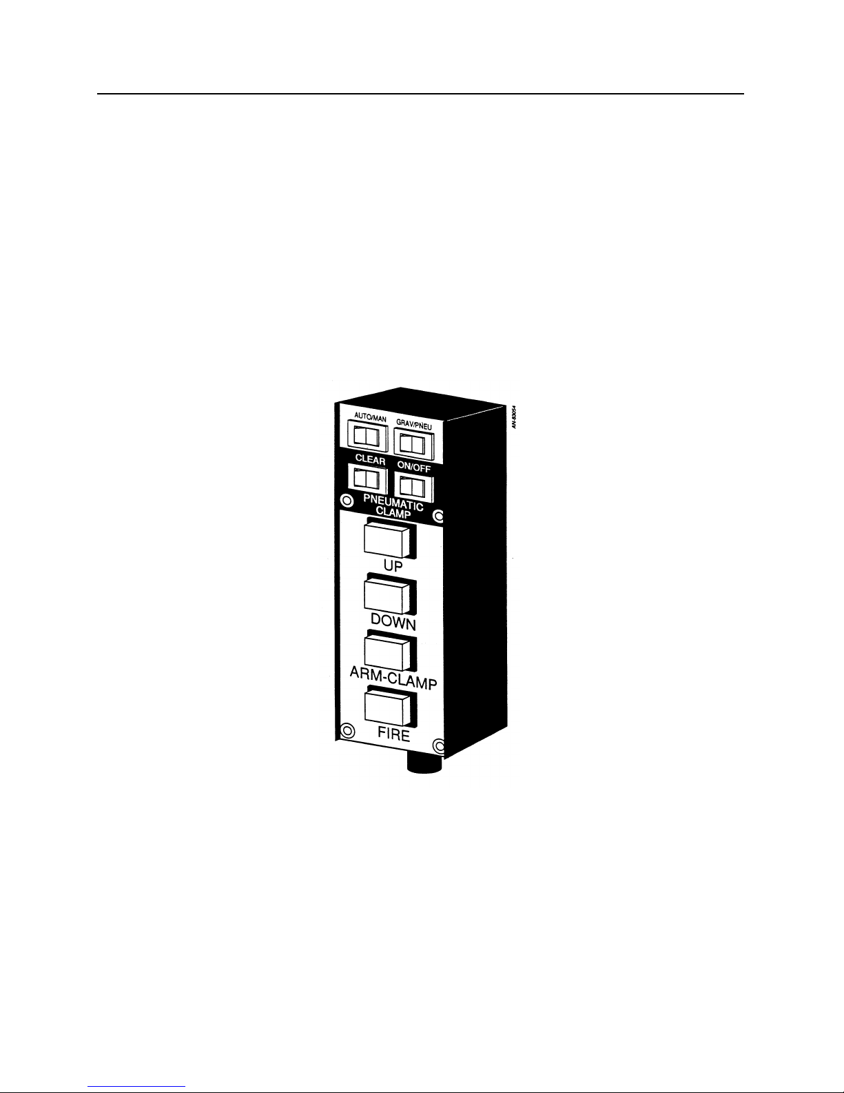
The hand-held pendent controls the operation of the Model 8250 and pneumatic clamp.
The pendent has three general sections:
• The mode section contains the automatic/manual switch and the gravity/pneumatic
switch.
• The pneumatic clamp section contains two switches that control the operation of the
pneumatic clamping fixture (if installed).
• The crosshead control section contains the manual controls for crosshead positioning.
The pendent is shown in Figure 4-1. The following sections describe each section.
Mode Section
Auto/manual (AUTO/MAN SWITCH)
The manual mode lets you directly control all functions of the Model 8250 and the
pneumatic clamp.
The automatic mode lets you control crosshead release only. All other functions are
handled automatically.
4-2
Figure 4-1. Control Pendent
Page 37

Function of
Controls
Gravity/Pneumatic (GRAV/PNEU SWITCH)
In the gravity mode, the crosshead can be dropped from any height. When gravity mode
operation is automatic, the hoist returns the crosshead to the position of the height limit
magnet mounted on the height scale.
In the pneumatic mode, the crosshead is pneumatically accelerated to higher velocities
than can be achieved in the gravity driven mode. The crosshead must be in the top
position for pneumatically assisted drops. As a result, when pneumatic mode operation is
automatic, the hoist returns the crosshead to the top position.
Pneumatic Clamp Section
Clamp on/off
The clamp on/off button controls the pneumatic clamp function. When the button is set
to ON, control of the pneumatic clamp is automatically included in the normal operating
sequences.
Clear
The CLEAR button operates the center cylinder of the pneumatic clamp. It is a
momentary switch that only works in the manual mode. It is used for manual stripping of
specimens and removing debris from the center bore of the pneumatic clamp.
Control Pendent
Crosshead Control Section
Up & Down
The UP and DOWN buttons control the hoist motor and raise or lower the latch assembly
and crosshead. These functions only work in the manual mode and are de-activated when
the system is in the pneumatic mode and the crosshead/latch is in the top position.
Arm
The ARM button readies the system in preparation for dropping the crosshead. On
systems outfitted with the pneumatic clamp, arm also causes the specimen to be clamped
in place. Arm only works if the button is illuminated. The safety enclosure doors must
be closed for the ARM button to light.
Fire
The FIRE button releases the crosshead and must be pressed after the ARM button is
pressed and before releasing the ARM button. This is a safety feature requiring that both
hands of the operator be on the pendent while the machine is dropping the weight. With
the pneumatic clamp installed there is approximately a 5-second time delay from the time
the ARM and FIRE buttons are pushed to the moment the weight is released. You must
hold down both buttons until the weight is released.
4-3
Page 38
Ancillary Machine Controls M14-13655-EN
Ancillary Machine Controls
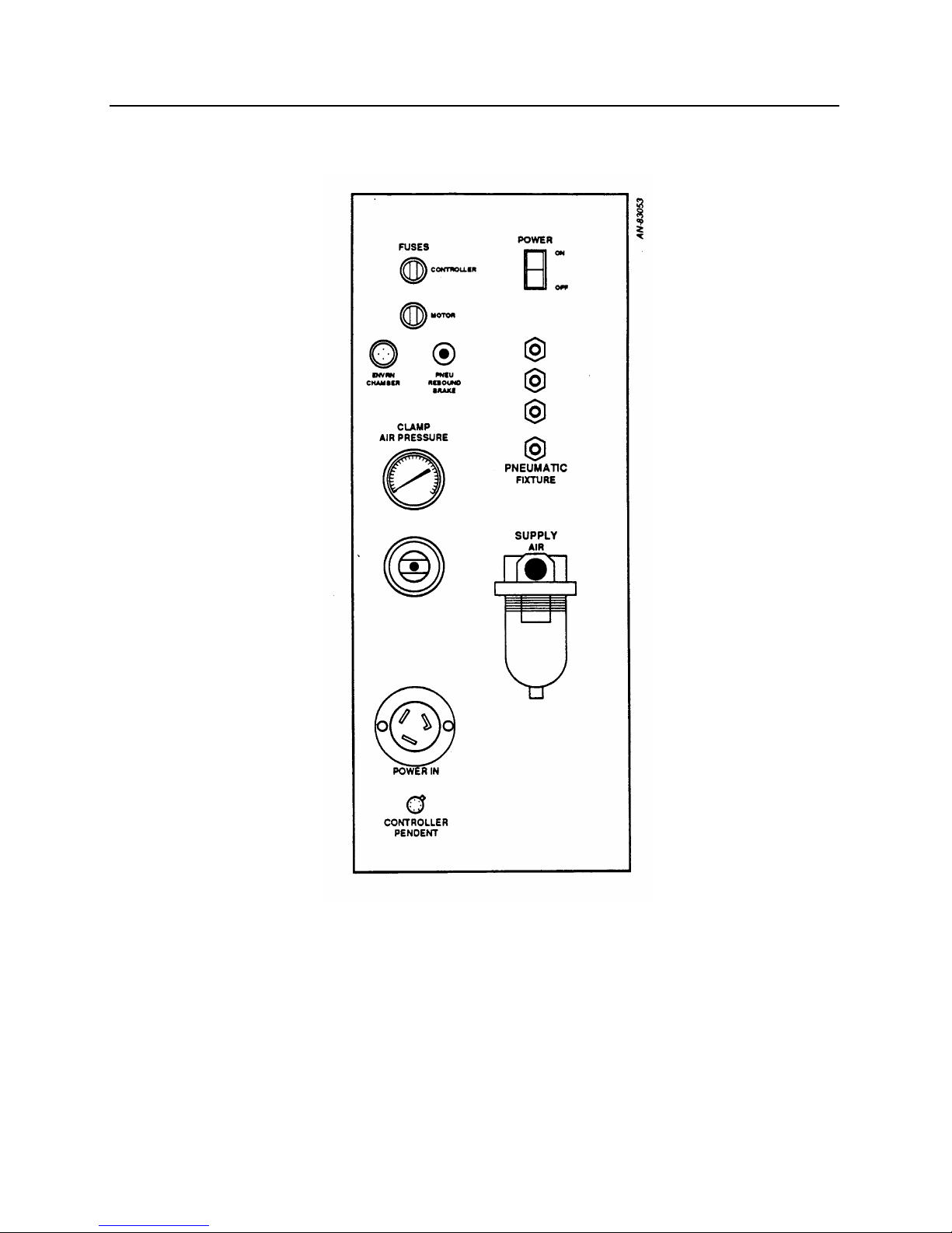
Environmental Chamber Connection (Envrn Chamber)
The Envrn Chamber connection is located on the left side of the Model 8250 motor
enclosure. This connection is used when the EC8250 environmental chamber is installed
on the Model 8250 and allows the chamber to interface with the Model 8250's safety
interlock system. Consult the EC8250 environmental chamber manual for specific
installation instructions.
4-4
Figure 4-1. Motor Enclosure
Page 39

Ancillary Machine Controls
Function of
Controls
Pneumatic Rebound Brake Connection (Pneu Rebound Brake)
The Pneu Rebound Brake connection is located on the left side panel of the Model 8250's
motor enclosure (see Figure 3-3).
This connection is used when the pneumatic rebound brake is installed on the Model
8250 and allows the Model 8250 to automatically reset the rebound brake after each test
sequence. Consult the Pneumatic Rebound Brake Manual for specific installation
instructions.
Pneumatic Clamp Pressure Regulator (Clamp Air Pressure)
The Clamp Air Pressure regulator is located on the left side panel of the Model 8250's
motor enclosure (see Figure 3-3).
If the Model 8250 is equipped with a pneumatic clamp, the pressure regulator can be used
to vary the amount of force applied by the clamp in securing the test specimen. The
amount of force applied is calculated by multiplying the value observed on the pressure
gauge by 6.47 to obtain the value in pounds, or by 28.75 to obtain the clamping force in
Newtons. For best function, the pressure should be set above 20 psi and the maximum
pressure should not exceed 100 psi.
The pressure regulator will have no effect on the pneumatic clamp unless the Clamp
On/Off button on the pendent is set to ON.
Pneumatic Assist Pressure Regulator (Pneumatic Assist Air Pressure)
The Pneumatic Assist Air Pressure regulator is located at the back of the Model 8250 on
top of the motor enclosure.
The regulator and gauge combination is used to vary the velocity of the crosshead when
the test machine is in pneumatic mode (GRAV/PNEU switch set to PNEU). The
maximum air pressure setting is 85 psi. The maximum velocity obtained is dependent on
the combination of fixturing and crosshead weight. Under no circumstances should the
heavier crosshead assemblies (greater than 50 lbs.) be accelerated above 14.5 ft/sec.
To adjust the knob for a desired velocity:
(a)
Turn the regulator knob until the gauge reads 40 psi.
(b)
Initialize the Instron Dynatup data system and access the VELOCITY command
(see the Data System Manual for details of the velocity command).
(c)
Fire the crosshead and observe the reported value for the velocity obtained.
(d)
If the velocity was lower than the desired value, increase the pressure supplied to
the pneumatic assist by turning the regulator knob clockwise. If the velocity was
higher than that desired, turn the regulator knob counter-clockwise. Observe the
gauge while turning the regulator knob. Large increases or decreases in pressure
correspond to large increases or decreases in velocity.
4-5
Page 40

Ancillary Machine Controls M14-13655-EN
(e) Continue to initialize the VELOCITY command and adjust the pressure
incrementally until the desired velocity is obtained.
4-6
Page 41

Preparation for
Outline
Chapter 5
Preparation for Use
• Adjusting the Velocity Detector.......................................................................5-2
• Adjusting the Stop Blocks and Shock Absorbers..............................................5-4
• Installing the Crosshead Weights.....................................................................5-6
5-1
Use
Page 42
Adjusting the Velocity Detector M14-13655-EN
FLAG
Adjusting the Velocity Detector
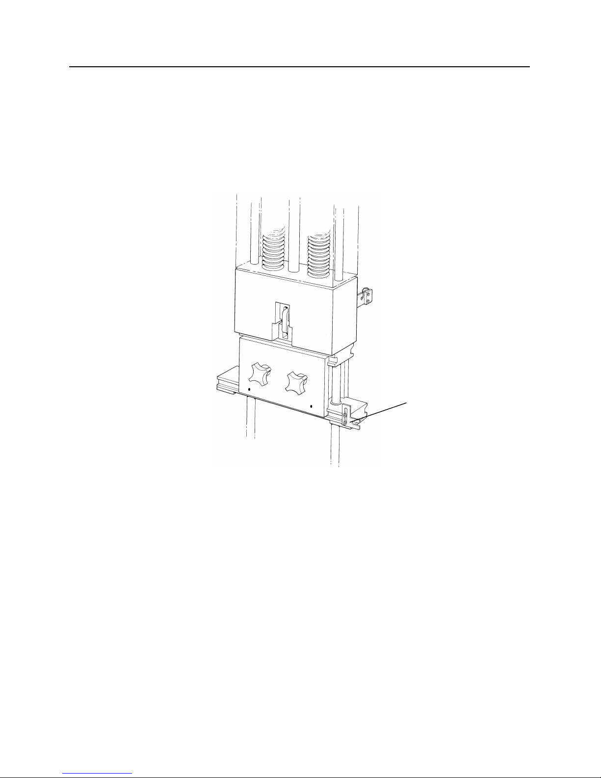
The steel flag on the edge of the crosshead should pass through the velocity detector
block before the tup hits the specimen. The velocity detector block is mounted on the
bracket to the right of the unit above the base plate.
Refer to the following sections for information on properly setting the velocity detector.
Refer to Figure 5-1 for an illustration of the velocity detector flag.
Figure 5-1. Velocity Detector Flag
Setting the Velocity Detector
To find the correct position of the velocity detector:
1.
With a specimen in the support fixture, lower the crosshead until the tup rests on the
specimen.
2.
Loosen the two screws that attach the velocity detector to its support bracket.
3.
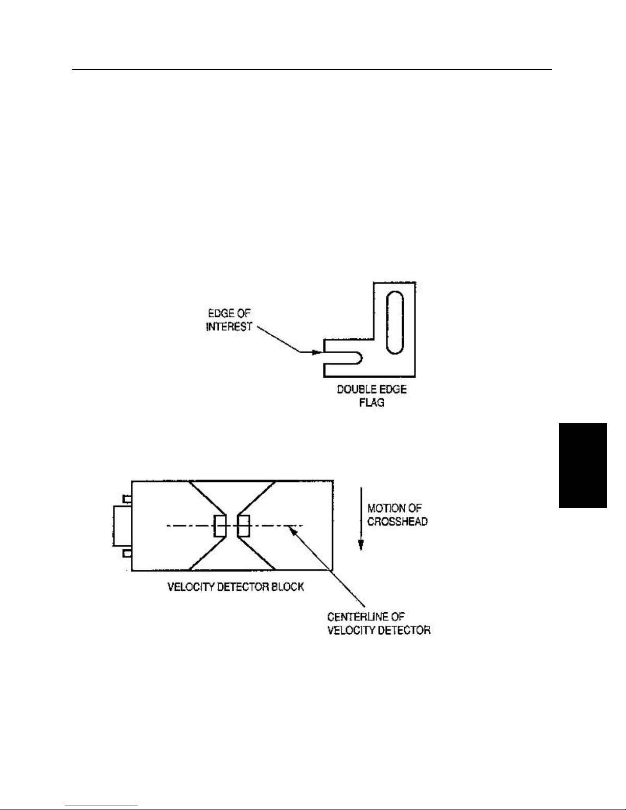
Slide the velocity detector up or down until the edge of interest of the flag (see Figure
5-2) is approximately 1/4 inch (6mm) below the center line of the velocity detector.
At high velocities, the velocity detector may have to be adjusted so that the edge of
the flag is more than 1/4 inch (6mm) below the center of the velocity detector.
4.
Check that the flag passes through the center of the velocity detector slot.
VELOCITY
DETECTOR
5.
Secure the velocity detector to the support bracket.
5-2
Page 43
Preparation for
Setting the Velocity Detector in Gravity Mode
The velocity of the crosshead when operating in the gravity mode can be determined
analytically with the following equation:
v = 2 gh
Where: v = theoretical velocity ft/sec (m/sec).
Adjusting the Velocity Detector
g = acceleration of gravity 32.17 ft/sec
(9.8 m/sec2).
h = drop height in ft (m)
2
Use
Figure 5-2. Velocity Detector and Flag
5-3
Page 44
Adjusting the Stop Blocks and Shock Absorbers M14-13655-EN
Adjusting the Stop Blocks and Shock Absorbers
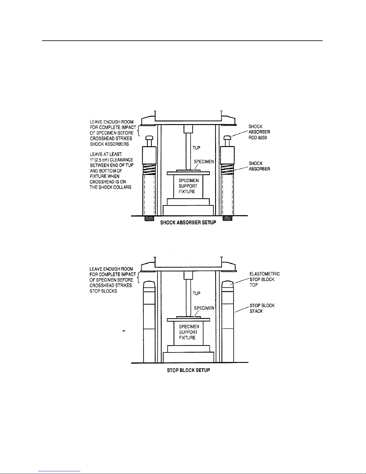
Refer to the following procedures for information on setting the stop block and shock
absorber height. Figure 5-3 illustrates the stop block and shock absorber setup.
Figure 5-3. Shock Absorber and Stop Block Setup
5-4
Page 45

Preparation for
Setting the Stop Block Height
CautionCaution
Make sure that the position of the stop blocks is such that the tup cannotMake sure that the position of the stop blocks is such that the tup cannot
touch any part of the specimen support fixture.touch any part of the specimen support fixture.
Stop blocks are used only in gravity mode operation. To set the stop block height:
1.
Using the 1 1/8 inch flat wrench provided with the machine, build stop blocks to the
appropriate height by screwing the various sections together. The two stop block
stacks must be the same height and have the same type of elastomeric stop block top.
Two hardnesses of stop block tops are provided.
2.
To find the correct stop block height, lower the crosshead and tup onto a specimen
placed in the specimen support fixture (anvil). The top of the stop blocks must be
positioned so that the crosshead will not contact the stop blocks until after the
specimen is completely broken or penetrated.
3.
The crosshead/tup must not be allowed to touch any part of the specimen support
fixture. Check this by removing the specimen and gently lowering the crosshead
onto the stop blocks. Be sure there is ample clearance between the tup and the fixture
to allow for deflection of the stop blocks on impact.
Adjusting the Stop Blocks and Shock Absorbers
4.
When the crosshead and tup are resting on a specimen, the optimum distance
between the top of the stop blocks and the bottom of the crosshead is generally about
1 inch (2.5cm). Specimens with large deflections to failure may require the stop
blocks to be set to a lower position.
Setting the Shock Absorber Height
CautionCaution
Always use the shock absorbers and Always use the shock absorbers and snubbers when operating in thesnubbers when operating in the
pneumatically assisted mode.pneumatically assisted mode.
The shock absorber can be used to arrest the crosshead under all circumstances.
However, due to the long piston stroke, which reduces the available deflection, the shock
absorbers are generally used only with high velocity testing.
To install the shock absorber assemblies:
1.
Screw the hydraulic shock absorber into place and tighten.
2.
Set the shock absorber to the correct height. To find the correct height: lower the
crosshead and tup onto a specimen placed in the specimen support fixture (anvil).
The top of the shock absorber rod must be positioned so that the crosshead will not
contact the shock absorber until after the specimen is completely broken or
penetrated. Shock absorber height is adjusted by adding and/or subtracting stop block
segments as necessary.
Use
5-5
Page 46
Installing the Crosshead Weights M14-13655-EN
Installing the Crosshead Weights
Each standard Model 8250 impact test machine is equipped with the following weight
sets:
1 set 5.5 lbs. (2.5kg)
l set 10.0 lbs. (4.5kg)
1 set 25.0 lbs. (11.3kg)
1 set 50.0 lbs. (22.7kg)
2 sets 25.0 lbs. (11.3kg) (with dowel pins)
The exact mass of each crosshead configuration is labeled on each weight set.
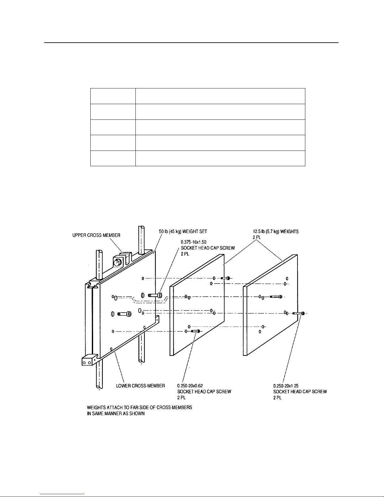
The following sections provide information on installing weights. Refer to Figure 5-3 for
an illustration of installing the add-on weights.
Figure 5-3. Installing the Add-on Weights
5-6
Page 47

Preparation for
CautionCaution
Make sure the hand knobs or bolts are securely tightened. If the weightMake sure the hand knobs or bolts are securely tightened. If the weight
plates are loose, the crosshead may bind on the guide columns.plates are loose, the crosshead may bind on the guide columns.
Therefore, check the crosshead assembly on a regular basis.Therefore, check the crosshead assembly on a regular basis.
The crosshead must be equally weighted on both the front and back.The crosshead must be equally weighted on both the front and back.
5.5 and 10 lb. (2.5kg) and 4.5kg) weight sets
Install 5.5 and 10 lb weight sets as follows:
1.
Lower the crosshead onto the stop blocks and remove the front and back weight
plates. Place the back weight plate (the one without the hand knobs) on the upper
and lower crossbars so the grooves fit into the crossbar ridges. Make sure the small
dowel pins in the lower crossmember are aligned.
2.
Hold the back weight plate in place while you fit the front weight plate onto the
crossbars. The threaded end of the hand knobs must engage the back weight plate.
3.
Tighten the hand knobs.
Installing the Crosshead Weights
4.
Slide the assembly up and down the guide columns. If it binds and shudders, lower
the crosshead to the stop blocks, loosen the hand knobs, rock the weights from side to
side and retighten. If the crosshead continues to bind or shudder, contact Instron
Dynatup.
25 lb. and 50 lb. (11.3kg and 22.7kg) weight sets
25 and 50 lb weight sets are installed in a similar manner as 5.5 and 10 lb weight sets
described in the previous section. However, 25 and 50 lb weight sets are secured by two
3/8 inch, 16 threads per inch bolts, rather than hand knobs.
75 lb. (34kg) Crosshead
A 75 lb. (34 kg) crosshead is built by installing a 50 lb. (22.7kg) with add-on plates, as
follows:
1.
Install the 50 lb. (22.7kg) weight set (refer to the previous section).
2.
Attach the add-on plates labeled 75 lbs. (34kg) by aligning the dowel pins on the
plates with the non-threaded holes on the crosshead. Secure with two 1/4 inch, 20
threads per inch x .62 inch (16mm) long socket-head cap screws on the opposing
diagonal from the dowel pins. Align the dowel pins on the plates. One add-on plate
should be mounted on the front and back of the 50 lb. (22.7kg) weight set.
Use
100 lb. (45kg) Crosshead
A 100 lb (45 kg) crosshead is built by installing a 75 lb. (34 kg) crosshead with add-on
plates, as follows:
5-7
Page 48

Installing the Crosshead Weights M14-13655-EN
1. Install the 75 lb. (34 kg) weight set (refer to the previous section).
2.
Align the dowel pins of the add-on plate labeled 100 lb. (45kg) and install onto the 75
lb. crosshead. Attach these plates with the two (2) 1/4-inch, 20 threads per inch x 1.0
inch (25mm) long socket-head cap screws.
Assembly Check-out
With lighter weights, lift the weights by hand to ensure that they glide easily up and
down on the guide columns. Alternatively, drop the crosshead from a known height and
verify that the velocity at the velocity detector is within a few percent <2% of the
theoretical value. Be sure to measure the drop height from the center line of the velocity
detector block to the second leading edge of the crosshead mounted flag.
5-8
Page 49

Outline
Chapter 6Chapter 6
Operation
• Performing a Test............................................................................................6-2
Operation
6-1
Page 50

Performing a Test M14-13655-EN
Performing a Test
Gravity Driven Operation
In the gravity mode, you can drop the crosshead from any height in manual or automatic
mode. When gravity mode operation is automatic, the hoist returns the crosshead to the
position of the height limit magnet mounted on the height scale.
The following sections detail a complete example of operation in both of these modes.
Manual Mode
WarningWarning
Install the “H” bar to prevent the crosshead from falling before workingInstall the “H” bar to prevent the crosshead from falling before working
within the safety enclosurewithin the safety enclosure
To operate the 8250 machine in gravity driven manual mode:
1.
Attach the desired weight to the crosshead.
2.
Set the top control pendent switches to MAN and GRAV. If a pneumatic clamp is
installed, set the clamp on/off switch to ON.
3.
Place the specimen in the specimen support fixture.
4.
Remove any tools, other foreign objects, and the safety "H" bar from the enclosure
and close the doors. The ARM button illuminates.
5.
Position the crosshead at the desired height using the UP and DOWN buttons.
6.
Press and hold the ARM button. The audible alarm sounds and the pneumatic clamp
(if installed) closes.
7.
While still holding the ARM button, press the FIRE button. The latch hook opens
allowing the crosshead to fall and strike the specimen.
8.
If a pneumatic clamp is installed, when you release the arm button , the clamp plate
rises. When a ductile specimen has been tested, it must be stripped from the tup. To
strip the specimen, press and hold the CLEAR button on the pendent. After the
center piston of the pneumatic clamp is fully raised, press the ARM button to bring
the clamp plate down and strip the specimen from the tup.
9.
Press the DOWN button to retrieve the crosshead. The latch mechanism stops
automatically and engages the crosshead.
10.
Press the UP button to raise the crosshead to the desired height.
11.
Insert the safety "H" bar.
6-2
Page 51

Automatic Mode
WarningWarning
Performing a Test
12. Remove the specimen.
13.
Press the CLEAR switch to raise the center piston on the pneumatic clamp, use the
wire brush provided to clear away debris.
Install the “H” bar to prevent the crosshead from falling before workingInstall the “H” bar to prevent the crosshead from falling before working
within the safety enclosurewithin the safety enclosure
To operate the 8250 machine in gravity driven automatic mode:
1.
Attach the desired weight set to the crosshead.
2.
Set the control pendent switches to AUTO, GRAV and, if a pneumatic clamp is
installed, set the clamp ON/OFF switch to ON. When the AUTO switch is pressed,
the crosshead automatically rises to the height determined by the magnetic switch.
3.
Set the pneumatic assist air pressure using the regulator on the top of the rear motor
enclosure.
4.
Place the specimen in the specimen support fixture.
5.
Remove any tools, other foreign objects, and the safety "H" bar from the enclosure
and close the doors. The ARM button illuminates.
6.
Press and hold the ARM button. The audible alarm sounds and the pneumatic clamp
(if installed) closes.
7.
While still holding the ARM button, press the FIRE button. The latch hook opens
allowing the crosshead to fall and strike the specimen.
8.
When a pneumatic clamp is installed, the system automatically strips the specimen
from the tup after the test.
9.
The latch assembly automatically retrieves the crosshead and raises it back to the
height of the magnetic switch.
10.
Insert safety "H" bar.
11.
Remove the specimen.
Pneumatically Assisted Operation
In the pneumatic mode, the crosshead is pneumatically accelerated to higher velocities
than can be achieved in the gravity driven mode. The crosshead must be in the top
position for pneumatically assisted drops. As a result, when pneumatic mode operation is
automatic, the hoist returns the crosshead to the top position.
Operation
6-3
Page 52

Performing a Test M14-13655-EN
When the crosshead is pneumatically assisted, you can operate the Model 8250 either
manually or automatically. The following sections detail a complete example in both of
these modes. In either case, the crosshead must start at the top position.
WarningWarning
Install the “H” bar to prevent the crosshead from falling before workingInstall the “H” bar to prevent the crosshead from falling before working
within the safety enclosurewithin the safety enclosure
CautionCaution
The shock absorber assemblies must be installed when operating in theThe shock absorber assemblies must be installed when operating in the
pneumatically assisted mode. Refer to adjusting the stop blocks andpneumatically assisted mode. Refer to adjusting the stop blocks and
shock absorbers in chapter shock absorbers in chapter 3 for more information.3 for more information.
Manual Mode
To operate the 8250 Machine in pneumatically driven manual mode:
1.
Attach the desired weight set to the crosshead. Do not accelerate 50 lb. (22.7kg), 75
lb. (34kg) or 100 lb. (45kg) crossheads to velocities above 14.5 ft./s (4.4 m/s).
2.
Set the top control pendent switches to MAN and PNEU. If the pneumatic clamp is
installed, set the clamp ON/OFF switch to ON.
3.
Set the pneumatic assist air pressure using the regulator on the top of the rear motor
enclosure.
4.
Place the specimen in the specimen support fixture.
5.
Using the UP button, raise the crosshead to the top position.
6.
Remove any tools, other foreign objects, and the safety "H" bar from the enclosure
and close the doors. The ARM button illuminates.
7.
Press and hold the ARM button. The audible alarm sounds and the pneumatic clamp
(if installed) closes.
8.
While still holding the ARM button, press the FIRE button. The latch hook opens
allowing the crosshead to fall and strike the specimen.
9.
If a pneumatic clamp is installed, the clamp plate rises when the ARM button is
released. When a ductile specimen has been tested, it must be stripped from the tup.
To strip the specimen, press and hold the CLEAR button on the pendent. After the
center piston of the pneumatic clamp is fully raised, press the ARM button to bring
the clamp plate down and strip the specimen from the tup.
10.
Press the DOWN button to retrieve the crosshead. The latch mechanism stops
automatically and engages the crosshead.
6-4
Page 53

Automatic Mode
WarningWarning
Performing a Test
11. Press the UP button to raise the crosshead to the desired height.
12.
Insert safety "H" bar.
13.
Remove the specimen.
14.
Press the CLEAR switch to raise the center piston on the pneumatic clamp. Use the
wire brush provided to clear away debris.
Install the “H” bar to prevent the crosshead from falling before workingInstall the “H” bar to prevent the crosshead from falling before working
within the safety enclosurewithin the safety enclosure
To operate the 8250 Machine in pneumatically driven automatic mode:
1.
Attach the desired weight to the crosshead. Do not accelerate 50 lb. (22.7kg), 75 lb.
(34kg) or 100 lb. (45kg) crossheads to velocities above 14.5 ft/s (4.4 m/s).
2.
Set the control pendent switches to AUTO, PNEU and, if a pneumatic clamp is
installed, set the clamp ON/OFF switch to ON. Note that when the AUTO button is
pressed, the crosshead automatically rises to the top position.
3.
Set the pneumatic assist air pressure, using the regulator on the top of the rear motor
enclosure.
4.
Place the specimen in the specimen support fixture.
5.
Remove any tools, other foreign objects, and the safety "H" bar from the enclosure
and close the doors. The ARM button illuminates.
6.
Press and hold the ARM button. The audible alarm sounds and the pneumatic clamp
(if installed) closes.
7.
While still holding the ARM button, press the FIRE button. The latch hook opens,
allowing the crosshead to fall and strike the specimen.
8.
When a pneumatic clamp is installed, the system automatically strips the specimen
from the tup after the test.
9.
The latch assembly automatically retrieves the crosshead and raises it back to the top
position.
Operation
10.
Insert safety "H" bar.
11.
Remove the specimen.
6-5
Page 54

Performing a Test M14-13655-EN
6-6
Page 55

Maintenance and
Troubleshooting
Outline
Chapter 7Chapter 7
Maintenance and Troubleshooting
• Scheduled Maintenance...................................................................................7-2
• Troubleshooting..............................................................................................7-5
7-1
Page 56

Scheduled Maintenance M14-13655-EN
Scheduled Maintenance
Maintenance Timeframe
The maintenance required on the Model 8250 varies with the frequency and type of
testing.
Perform a complete check of the machine after the first 10 tests performed on the
machine. After that initial check, make a complete check every week for the next 3-4
weeks. Continue to perform complete safety checks regularly every three months for as
long as your machine is in regular use.
Always service the machine prior to operation after an extended idle period.
Consult with Instron Dynatup if you have any questions or are confronted with a situation
not addressed in this manual.
Regular Maintenance Steps
The following checks and procedures should be performed during regular maintenance.
• Clean the glass safety enclosure with a soft cloth and mild detergent or window
cleaner.
• Clean the guide columns with thinner and, if necessary, fine steel wool. Apply a very
thin coat of light machine oil or silicon lubricant to the columns after cleaning. Do
not use a heavy oil or grease. Do not apply solvent to the crosshead bushings and be
sure to remove any steel wool fragments when finished.
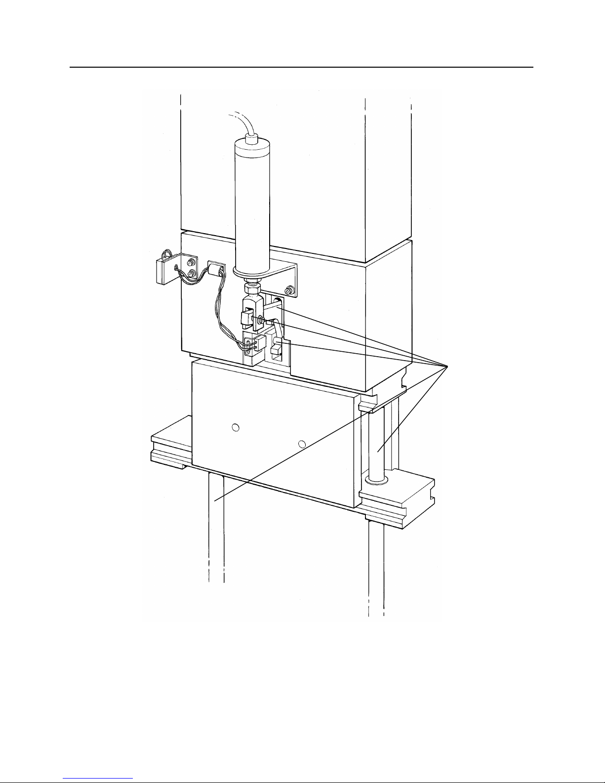
• Occasionally lubricate the latch-pin roller bearings on the crosshead and the hook pin
with light machine oil. Apply a drop of oil to each bearing. Refer to Figure 7-1 for
an illustration of lubrication points.
• Check the condition of the hoist cable by raising and lowering the latch assembly.
Note any wear and replace if necessary. Be sure to:
• Verify that the cable is wrapping uniformly around the hoist hub. To view the
hub, remove the small cover plate surrounding the cable on top of the rear motor
enclosure.
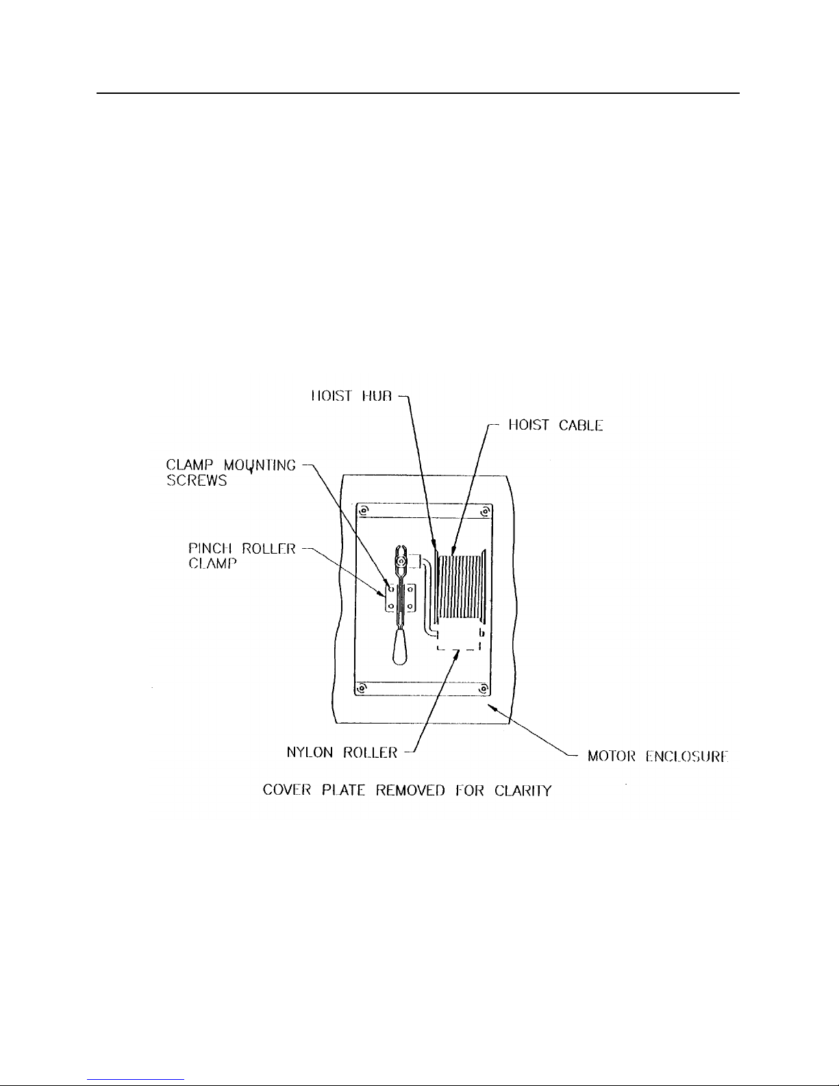
• Check the alignment of the pinch roller that presses on the hoist hub. The nylon
roller should be pressing uniformly and with moderate force against the hub. If
the pinch roller is not aligned, readjust the clamp mounting screws. Also, if the
pinch roller makes a grinding noise when hoist is in operation, apply a coat of
light machine oil.
• Check that the crosshead slides freely over the length of the guide columns. If there
is any resistance to full crosshead movement, visually examine the crosshead for
damage. Next, install the stop block stacks and drop the crosshead from a few inches
7-2
Page 57

Scheduled Maintenance
Maintenance and
Troubleshooting
onto the stop blocks. Loosen the bolts on the crosshead, shake the crosshead and
then re-tighten. If the crosshead still does not slide freely, contact Instron Dynatup.
• Check and tighten the screws on the velocity detector and verify that the flag on the
crosshead passes through the center of the velocity detector slot.
• Check the air filter/water trap mounted on the rear motor enclosure. Push up on the
valve located at the bottom of the bowl to drain.
• Check the condition of all electrical wiring and conduits including the power cord
and pendent cable.
• Check the air system for air leaks. Investigate any persistent hissing.
• Check that the interlock switches are operational. Open each door to verify that the
yellow pendent light goes off. If not, check the interlock switch and immediately
suspend use of the machine until repairs are made.
• Check the shock absorbers and/or stop blocks for damage. The shock absorbers
should not leak oil and should offer mild resistance when compressed by hand. The
elastomeric stop block tops should be intact. Replace the tops immediately when
damaged. Variances in the performance of the two stop block tops or shock
absorbers can damage the crosshead.
• Visually check the tup, tup insert and tup cables for damage.
• Check the safety enclosure door handles, hinges and the back safety enclosure
mounting bolts for any looseness. Tighten, if necessary.
• Check that the two large main springs are securely attached to their connecting rods.
The springs are exposed when the air supply is turned off.
• Check that the striker plates are securely held in place. These plates are mounted to
the bottom of the crosshead and protect the lower crosshead from the shock absorbers
or stop blocks.
• Check the tightness of the guide columns. They should not be able to turn. If the
guide columns are loose, contact Instron Dynatup.
• Release cable tension and check that the sheaves in the hoist pulley bracket rotate
freely. These pulleys can be reached through the opening in the back of the top
enclosure.
• Tighten all bolts on fixtures, baseplate, tablebase, etc.
7-3
Page 58
Scheduled Maintenance M14-13655-EN
Figure 7-1. Lubrication Points
LUBRICATION
POINTS
7-4
Page 59

Maintenance and
Troubleshooting
Troubleshooting
Many problems can be easily determined and solved. Before attempting any service
inside the motor enclosure of the machine, check the other possible solutions.
Hoist Motor
Refer to Figure 7-2 for an illustration of the Hoist Hub and Pinch Roller Assembly.
Problem:
Hoist motor will not go up or down:
Possible Solutions:
• Check motor fuse on motor control console. Replace with 6 1/4 AMP slo-blow, if
necessary.
• Check that the pendent AUTO/MAN switch setting is set to manual (MAN). If the
system is in the automatic (AUTO) mode, the hoist will not operate. To move the
crosshead up or down, the switch must be set to manual (MAN).
Troubleshooting
• Check that the pendent PNEU/GRAV switch setting is set to gravity mode (GRAV).
If the crosshead is in the top position and the pendent is set to the pneumatic mode,
the crosshead cannot be lowered. To lower the crosshead, the switch must be set to
the gravity mode.
• Check door interlock switches, pendent cable, air connections and air supply. The
hoist motor will only run if the yellow pendent light is on and pressurized air is
connected to the system.
• If motor clicks but will not run, disconnect the power and remove the back panel of
motor enclosure. Check the mechanical relay mounted in the socket to the left of the
hoist motor. This should be tightly secured and not burned.
Problem:
Latch stops part way to the top, or will not travel smoothly:
Possible Solutions:
• Check the height scale switch. Remove switch or run in manual mode.
• Check the crosshead and latch assemblies for binding. Perform a velocity check as
described in the section called Installing the Crosshead Weights in Chapter 3 under
the heading, "Assembly Check-out." Check the latch assembly binding by pulling
the hoist cable at the rear of the machine and raising the latch. The latch should
move freely. If latch or crosshead are binding, contact Instron Dynatup.
7-5
Page 60
Troubleshooting M14-13655-EN
Problem:
Continually blowing fuses:
Possible Solutions:
• Check that you are using the correct size fuse: a 6 1/4 AMP slo-blow fuse (100-120V
power) for the hoist motor (3 AMP fuse for 240V power).
• If fuses only blow when the weights are raised to the top, Contact Instron Dynatup.
• If fuses blow when pulling the tup out of specimens, tup may be penetrating material
that is too thick or too ductile for the motor to pull the tup free. Contact Instron
Dynatup.
Figure 7-2. Hoist Hub and Pinch Roller Assembly
7-6
Page 61

Maintenance and
Troubleshooting
Hook
Troubleshooting
Problem:
Hook will not open
Possible Solutions:
• Check the safety enclosure doors and make sure that the air supply is on. The hook
should open by simultaneously pressing the yellow ARM button and the red FIRE
button. The ARM button must be illuminated, and the FIRE button must light when
pressed with the ARM button. If the ARM button is not illuminated, the interlocks
are indicating an unsafe condition. Check the safety enclosure doors and make sure
that the air supply is on. Once the ARM and FIRE buttons are pressed, it may take
up to 5 seconds for the weight to drop.
• Check switch next to hook for damage. Contact Instron Dynatup if you suspect it is
damaged.
Problem:
Hook will not close
Possible Solution:
• Check the switch next to the hook for damage. Contact Instron Dynatup if you
Other Problems
Problem:
Abnormal Velocity
Possible Solution:
• Check that the guide columns are free from dirt; the weight sets are not bent or
Problem:
Abnormal data collection
Possible Solution:
suspect it is damaged.
damaged, the flag is not loose or damaged, and that the velocity detector block is not
damaged.
• Check the mounting of the tup, tup insert, specimen or fixture; check that the velocity
detector or flag is properly adjusted. Problems with data or data collection are often
unrelated to the data system.
7-7
Page 62

Troubleshooting M14-13655-EN
7-8
Page 63

Apendix AApendix A
Glossary
Term Definition
ASTM American Society of Testing and Materials. Publishes many test method documents.
Brittle A failure mode. Specimen generally does not deflect far before cracking begins.
Charpy Notched or un-notched simple beam test method. Also called three-point bend.
Components End use or finished product to be tested.
Glossary
Crosshead
Deflection Elastic and plastic deformation of a test specimen during an impact event.
Detector block
Ductile A failure mode. Specimen absorbs a large amount of energy with large deflection. In a
Failure mode The way in which a specimen fails during an impact event.
Flag Precision device used to interrupt infrared light beam for velocity measurements.
Fracture toughness Resistance of a material to propagation of an initiated crack under impact conditions.
Impact A situation in which a moving body strikes another body either at rest or moving.
Impact energy Total potential and kinetic energy of crosshead at impact.
Impact velocity Rate of speed of the falling crosshead at point of impact.
Incipient damage During the impact event, the point at which the specimen first experiences any damage.
IZOD Notched or un-notched cantilever beam test method.
Multi-axial test Term given to puncture testing due to the multi-axial stress state of the specimen.
NTA Normalize To Area . Energy absorption as a function of specimen cross-section.
Falling weight assembly (weights, structural members, etc.) attached to Tup. Also referred
to as “hammer” in setup menu or when discussing a pendulum.
Precision device containing infrared light beam. Passing flag breaks beam and allows for
measurement of velocity.
plastics puncture test, the specimen shows only plastic flow at penetration point.
Also referred to as: “onset of damage”, “first crack”, “fracture initiation point”.
NTT Normalize To Thickness. Energy absorption as a function of specimen thickness.
Rebound test A test in which the tup bounces off of the specimen and is arrested prior to second hit.Also
called “single impact rebound test”. Often used to find incipient damage point.
Specimen An item to be tested. Usually manufactured in accordance with a test method.
Theoretical velocity Velocity of a free falling body due to the force of gravity (does not take into effect
mechanical friction and wind resistance).
Tup Force transducer or load cell with striking tip.
Velocity slowdown Decrease in crosshead velocity from impact to the point of maximum load.
A-1
Page 64

Glossary M14-13655-EN
A-2
 Loading...