

Page 1

SERVICE MANUAL
Dynatron
Dynatron
i
®
850plus &
®
550plus
Page 2

Dynatron® 850plus & 550plus
CAUTION: Federal law restricts this device to sale by or on the order of a physician,
chiropractor, physical therapist, or dentist licensed by the law of the state in which said
person practices to use or order the use of the device.
IMPORTANT: Before treating a patient with the Dynatron 850plus or the Dynatron
550plus, see the “Contraindications, Warnings, and Precautions” in this manual.
INDICATIONS FOR USE:
Muscle stimulation therapy delivered by the Dynatron 850plus and 550plus is indicated
for the following uses:
1. relaxation of muscle spasm;
2. prevention or retardation of disuse atrophy;
3. increasing local blood circulation;
4. muscle re-education;
5. immediate postsurgical stimulation of calf muscles to prevent venous thrombosis; and
6. maintaining or increasing range of motion.
Interferential, premodulated, high volt, and microcurrent therapy are indicated for
providing temporary relief of chronic intractable pain.
INDICATIONS FOR ULTRASOUND USE:
Ultrasound therapy is intended to generate deep heat within body tissues for the treatment
of selected medical conditions such as relief of pain, muscle spasms, and joint
contractures, but not for the treatment of malignancies.
(21 CFR 890.5300)
Dynatron® 850plus and Dynatron® 550plus Service Manual
Revised June 2004
© Copyright 1997
Dynatronics Corporation
7030 Park Centre Drive
Salt Lake City, UT 84121
(801) 568-7000 (800) 874-6251
ALL RIGHTS RESERVED
ii
Page 3

Dynatron® 850plus & 550plus
Table of Contents
Section I
Introduction I
Introduction to the Dynatron 850plus™ and 550plus™ ........................................................................ 2
New Features..........................................................................................................................................2
Treatment Options..................................................................................................................................3
Simplified Setup.....................................................................................................................................4
Before You Treat a Patient.....................................................................................................................4
How to Use This Manual........................................................................................................................ 4
Installation and Features............................................................................................................................ 5
Unpacking ..............................................................................................................................................5
Standard Accessories.............................................................................................................................. 5
Soundheads and Probes.......................................................................................................................... 6
Accessories............................................................................................................................................. 6
Dynatron 850plus and Dynatron 550plus Physical Features.................................................................. 7
Instructions for Using Toggle Keys .....................................................................................................13
Time and Power Displays..................................................................................................................... 15
Ultrasound Heads (Dynatron 850plus only)......................................................................................... 15
Microcurrent Probes (optional accessory)............................................................................................ 16
High Volt Probe (optional accessory) ..................................................................................................17
Quick Reference of Special Key Presses .................................................................................................18
Section II
Operation and Treatment Instructions
General Operating Instructions............................................................................................................... 20
Power On/Off ....................................................................................................................................... 20
Basic Treatment Setup.......................................................................................................................... 20
Conductance Bar Graph ....................................................................................................................... 21
“LEAD” Warning - No Patient Current ...............................................................................................22
Interferential / Premodulated Instructions............................................................................................. 24
Basic Interferential / Premod Setup...................................................................................................... 24
Detailed Interferential / Premodulated Setup .......................................................................................25
Interferential / Premodulated Default Settings ..................................................................................... 28
iii
Page 4

Dynatron® 850plus & 550plus
Biphasic / Russian Instructions ................................................................................................................29
Basic Biphasic / Russian Setup.............................................................................................................30
Detailed Biphasic / Russian Setup ........................................................................................................30
Biphasic / Russian Default Settings......................................................................................................33
High Volt Instructions...............................................................................................................................35
Set Up High Volt Treatment with Electrodes .......................................................................................35
Set Up High Volt Treatment with Optional Probe................................................................................36
Basic High Volt Setup ..........................................................................................................................37
Detailed High Volt Setup......................................................................................................................37
High Volt Default Settings....................................................................................................................41
Microcurrent Instructions ........................................................................................................................42
Basic Microcurrent Setup .....................................................................................................................42
Microcurrent Treatment Time...............................................................................................................43
Detailed Microcurrent Setup.................................................................................................................43
Audio Tone ...........................................................................................................................................46
Microcurrent Default Settings...............................................................................................................46
How To Use Microcurrent Probes ........................................................................................................46
Ultrasound Instructions ............................................................................................................................48
Soundhead Warming.............................................................................................................................48
Turn Soundhead Warming Off / On .....................................................................................................49
Basic Ultrasound Setup.........................................................................................................................49
Detailed Ultrasound Setup ....................................................................................................................49
Ultrasound Default Settings..................................................................................................................51
Patient Coupling ...................................................................................................................................51
Poor Coupling.......................................................................................................................................52
Ultrasound Coupling Bar Graph ...........................................................................................................52
Head Temperature Hot..........................................................................................................................53
Head Temperature Bar Graph...............................................................................................................54
Display Watts or W/cm2.......................................................................................................................54
Combination Therapy Instructions .........................................................................................................56
Comboplus™ ........................................................................................................................................56
Stim Through the Soundhead................................................................................................................57
Combination Therapy Setup .................................................................................................................58
Modify Treatment .................................................................................................................................60
Combination Default Settings...............................................................................................................61
iv
Page 5

Dynatron® 850plus & 550plus
Simultaneous Treatments......................................................................................................................... 62
Set Up A Second Treatment................................................................................................................. 62
Modify Simultaneous Treatments ........................................................................................................63
Stop One Treatment.............................................................................................................................. 63
Setting Defaults .........................................................................................................................................64
Save New Defaults ............................................................................................................................... 64
Restore Factory Defaults ...................................................................................................................... 65
Interferential Default Settings ..............................................................................................................65
Premodulated Default Settings............................................................................................................. 65
Russian / Biphasic Default Settings ..................................................................................................... 65
High Volt Default Settings...................................................................................................................66
Microcurrent Default Settings .............................................................................................................. 66
Ultrasound Default Settings .................................................................................................................66
Combination Default Settings .............................................................................................................. 66
Battery Operation ..................................................................................................................................... 67
Battery Requirements........................................................................................................................... 68
Battery Life........................................................................................................................................... 68
Section III
General Modality Information
Interferential and Premodulated Therapy .............................................................................................70
Interferential (Quadpolar) Therapy ......................................................................................................70
Premodulated (Bipolar) Therapy.......................................................................................................... 70
Target.................................................................................................................................................... 71
Why Is Target Better? ..........................................................................................................................71
Sweep ...................................................................................................................................................72
Interferential Electrode Placement ....................................................................................................... 72
Russian / Biphasic Therapy...................................................................................................................... 73
Russian Stimulation.............................................................................................................................. 73
Biphasic Stimulation ............................................................................................................................73
Biphasic / Russian Parameters.............................................................................................................. 73
High Volt Therapy .................................................................................................................................... 76
High Volt Therapy with Electrodes...................................................................................................... 76
High Volt with Optional Probes........................................................................................................... 76
High Volt Waveform............................................................................................................................ 76
High Volt Settings................................................................................................................................ 76
v
Page 6

Dynatron® 850plus & 550plus
Microcurrent Therapy ..............................................................................................................................78
Microcurrent Therapy with Electrodes .................................................................................................78
Microcurrent Therapy with Probes .......................................................................................................78
Microcurrent Waveforms......................................................................................................................78
Microcurrent Settings............................................................................................................................78
Ultrasound Therapy..................................................................................................................................79
About Ultrasound..................................................................................................................................79
SmartHeads...........................................................................................................................................79
Patient Coupling ...................................................................................................................................79
Soundhead Temperature .......................................................................................................................80
Section IV
Contraindications, Warnings, and Precautions
Contraindications, Warnings, & Precautions for Interferential, Premodulated, Russian, Biphasic, and
High Voltage Pulsed Stimulation .............................................................................................................82
Contraindications ..................................................................................................................................82
Warnings...............................................................................................................................................82
Precautions............................................................................................................................................83
Treatment Setup Warnings ...................................................................................................................84
Adverse Effects.....................................................................................................................................84
Use Only Dynatronics Accessories With This Device .........................................................................84
Contraindications, Warnings, & Precautions for Microcurrent Treatment........................................85
Indications for Use................................................................................................................................85
Contraindications ..................................................................................................................................85
Warnings...............................................................................................................................................85
Precautions............................................................................................................................................86
Adverse Reactions ................................................................................................................................86
Contraindications, Warnings, & Precautions for Ultrasound Treatment ...........................................87
Contraindications ..................................................................................................................................87
Precautions............................................................................................................................................88
Warnings...............................................................................................................................................88
Electrotherapy Usage Cautions................................................................................................................89
Carbon Electrodes.................................................................................................................................90
Self-Adhesive Electrodes......................................................................................................................91
Combination Treatment Usage Cautions ..............................................................................................92
Lead Wires............................................................................................................................................92
Test Leads .............................................................................................................................................93
vi
Page 7

Dynatron® 850plus & 550plus
Current Limit........................................................................................................................................ 93
Current Limit Warning......................................................................................................................... 94
Microcurrent Usage Cautions.................................................................................................................. 95
Ultrasound Usage Cautions...................................................................................................................... 96
Applicator Movement........................................................................................................................... 96
Patient Susceptibility............................................................................................................................ 96
Potential for Burns................................................................................................................................ 96
Output Power........................................................................................................................................ 97
Penetration of Ultrasound Waves......................................................................................................... 97
Coupling...............................................................................................................................................97
Section V
Ultrasound Technical Information
Ultrasound Regulation............................................................................................................................ 100
Beam Profile ............................................................................................................................................ 101
Enter Soundhead Parameters................................................................................................................ 104
New SmartHeads™ ............................................................................................................................ 104
Using Older Model Soundheads With the 50 Series Plus .................................................................. 104
Calibration Procedure............................................................................................................................106
Problem Solving ...................................................................................................................................... 109
Soundhead Temperature Too Hot ......................................................................................................109
Cooling the Soundhead ...................................................................................................................... 109
Whirlpool Treatments......................................................................................................................... 109
Soundhead Temperature Too Cold..................................................................................................... 110
No Soundhead ....................................................................................................................................110
Other Error Messages in the Display.................................................................................................. 110
Section VI
Technical Information
General Specifications ............................................................................................................................ 114
Dynatron 850plus and 550plus Specifications ................................................................................... 114
Stim Specifications............................................................................................................................. 114
Microcurrent Specifications ............................................................................................................... 114
High Volt Specifications .................................................................................................................... 115
Ultrasound Specifications (Dynatron 850plus only) .......................................................................... 115
vii
Page 8

Dynatron® 850plus & 550plus
Environmental Conditions ..................................................................................................................115
Safety Features of the Dynatron 850plus and 550plus .......................................................................115
Care and Cleaning Instructions...........................................................................................................116
Suggested Maintenance Schedule.......................................................................................................116
Routine Ultrasound Calibration Inspections (Dynatron 850plus only)...............................................117
Software Updates................................................................................................................................118
Returning a Unit for Repair ................................................................................................................118
Definition of Symbols.........................................................................................................................119
Equipment Classification....................................................................................................................119
Disposal of Equipment and Accessories.............................................................................................119
Additional Technical Information Available (for Technicians Only).................................................120
FDA Compliant Electrodes and Lead Wires.......................................................................................120
Medical Device Reporting Requirements..............................................................................................121
Reporting any Incident of Patient Discomfort ....................................................................................121
Section VII
Service
Processor Interaction ..............................................................................................................................124
Processor Interaction with the Keyboard and Displays ......................................................................124
Processor Interaction with Oscillators ................................................................................................124
Processor Interaction with the Output Jacks.......................................................................................124
Processor Control of Output Waveforms............................................................................................124
Basic Trouble Shooting Techniques.......................................................................................................125
Hands-On Testing Pads and Leads .....................................................................................................125
Installing Software Updates....................................................................................................................126
Installing Replacement Parts..................................................................................................................126
Section VIII
Schematics and QC Check Lists
viii
Page 9

Dynatron® 850plus & 550plus
Section I
Introduction
1
Page 10

Dynatron 850plus™ and 550plus™
The Dynatron 850plus and Dynatron 550plus offer the practitioner a wide range of treatment
options in a single device. Both devices provide interferential and premodulated therapy,
high voltage pulsed stimulation, Russian and biphasic stimulation, and microcurrent. The
850plus also includes ultrasound and combination therapy.
The devices include the advantages of earlier Dynatronics models, such as customizable
treatments with convenient setup. In addition, these units are smaller and lighter in weight
than earlier models and now offer the option of battery operation, making the devices truly
portable. One additional channel is now dedicated to high volt therapy, allowing a greater
variety of simultaneous treatments. The manufacturer’s warranty for these devices is now
two years (see full warranty details at the back of this manual).
This manual provides operator information and instructions for both of these models. The
sections that discuss ultrasound and combination treatments apply only to the Dynatron
850plus model. All other sections of this manual apply to both devices. Sections of this
manual that apply only to the Dynatron 850plus are clearly marked.
New Features
For models having software greater than Rev. 1.01 or later, the following new features have
been added (effective January 1998).
• Conductance Bar Graph. A graphical representation of conductivity during and
• Ultrasound Coupling Bar Graph. Shows soundhead coupling during an ultrasound
• Soundhead Temperature Bar Graph. Indicates when soundhead temperature is too hot
• “Lead” warning. A new warning displayed if the device detects an open circuit,
• New warnings notifying the user when the soundhead is too hot, or when the soundhead
These new features are described in greater detail in the treatment instructions later in this
manual. The determine the software revision level for the Dynatron device, power the device
on and observe the number shown in the Time display at the end of the device’s startup
routine.
Dynatron® 850plus & 550plus
Introduction to the
interferential, premodulated, or microcurrent treatment.
treatment.
during a treatment.
indicating no patient current is being delivered and the treatment setup must be inspected.
is not detected by the device
Introduction
2
Page 11

Treatment Options
The following modalities are provided by both the Dynatron 850plus and the Dynatron
550plus:
Interferential Therapy: This traditional therapy, delivered with two channels and
four electrodes, also includes Dynatronics’ patented Target feature for easy location
of the treatment site and delivery of the full interferential beat where it is needed.
You can select the high frequency range, the low frequency range, or both, along
with Target. Or select Sweep when you want to deliver the current over a more
general area. You can also customize the frequency settings for individual treatments
or save a unique default setting.
Premodulated Therapy: Ideal for treating areas where four electrode-placement is
not practical, this modality extends the versatility of the device by offering a
premodulated interferential current using one channel and two electrodes.
Biphasic Stimulation: This option provides muscle stimulation using a sinusoidal
biphasic waveform with pulse widths, ranging from 50 to 400 microseconds. It
offers normal, co-contraction and reciprocal contraction modes, selectable on/off
cycle times and ramp times, and customizable pulse rate and pulse width.
Russian Stimulation: With this modality, you can deliver muscle stimulation
treatments selecting from an array of options including normal, co-contraction and
reciprocal contraction, selectable on/off cycle times and ramp times, and
customizable pulse rate and pulse width.
High Voltage Pulsed Stimulation: This traditional electrotherapy modality offers a
pulsed, monopolar current with pulse widths in the microsecond range and pulse rates
ranging from 1 to 200 Hz utilizing a twin-peak monophasic waveform. Polarity,
on/off cycle time, and ramp time are selectable, and pulse rate may be customized for
each treatment. Treatment may be delivered using either electrodes or optional
probes.
Microcurrent Therapy: Microcurrent treatment may be delivered using two
electrodes for unattended therapy, or the optional hand-held probes for manual
treatment. You may select the desired polarity and customize the frequency and
intensity. An audible tone allows you to monitor conductance.
The following additional modalities are provided with the Dynatron 850plus (not included
with the Dynatron 550plus):
Ultrasound Therapy: The Dynatron 850plus includes Dynatronics’ patented multifrequency ultrasound capability. Soundheads are available in 1 cm
and 10 cm
offers 2 and 3 MHz.) Duty cycle options are 10, 20, or 50 percent, or a continuous
duty cycle.
Combination Therapy - Comboplus™: Dynatronics’ new Comboplus feature gives
you almost unlimited options in setting up a combination treatment with the
Dynatron 850plus. Now you can combine an ultrasound treatment with any singlechannel electrotherapy modality provided by this device, including Premodulated,
Biphasic, Russian, High Volt, or Microcurrent. In addition, combination therapy is
Dynatron® 850plus & 550plus
2
2
sizes. Each soundhead offers 1, 2, and 3 MHz. (The 1 cm2 soundhead
, 2 cm2, 5 cm2,
3
Page 12

no longer restricted to just one channel—any channel may be used. This means you
may set up a combination treatment using any of the three electrotherapy output
jacks. Combination therapy offers simultaneous treatment time and allows you to
select from all the available options for both modalities used in the combined
treatment.
Simplified Setup
The unique design of the Dynatron 850plus and 550plus front panels means treatment setup
has never been easier. A few simple key presses are all you need to fully set up a treatment.
The careful grouping of available options for each modality ensures that you can easily see
and select from the appropriate options for that modality.
Each modality offers default settings which are automatically selected when the modality is
selected—saving time in the treatment setup. You can change these defaults to match your
own most common treatment setups to reduce setup time to a matter of seconds.
Before You Treat a Patient
Before administering a treatment to a patient with the Dynatron 850plus or 550plus, you
should familiarize yourself with all the operating instructions for the modality used, as well as
the contraindications, warnings, and precautions for that modality.
You should also read in this manual general information about each of the modalities. In
addition to the information provided in this manual, consult other published sources for
additional application and safety instructions regarding use of each type of therapy.
How to Use This Manual
This manual is organized to help you learn how to use your Dynatron 850plus and 550plus
device, and to provide easy reference for looking up specific instructions or information. The
information in the manual is grouped as listed below. Note that all treatment instructions for all
modalities are in one section, and that all contraindications, warnings, and precautions for all
modalities are provided together in another section.
This grouping of information makes it easy for you to find what you are looking for. To assist
you further, descriptive titles appear at the foot of each page to help to identify immediately
what section you are in. Familiarize yourself with the organization and presentation of this
manual to make best use of the information provided.
Section I: Introduction, Installation and Features
Section II: Operation and Treatment Instructions
Section III: General Modality Information
Section IV: Contraindications, Warnings, and Precautions
Section V: Ultrasound Technical Information
Section VI: General Technical Information
Section VII: Patient Information
Dynatron® 850plus & 550plus
Introduction
4
Page 13

Installation and Features
Unpacking
When you receive the unit, immediately unpack it and all accessories and check for possible
damage, obvious or concealed. In case of damage, immediately notify the carrier and take
any steps necessary to file a claim for the damage sustained. Do not destroy the shipping
carton. The carton should be reused if the device must be shipped for any reason. The carton
is specially designed to protect the unit from shipping damage. Improper packaging of the
unit during transport can result in damage and invalidate the warranty.
Complete the warranty registration form and return it to Dynatronics within 10 days of
purchase. This is essential to insure you are not billed for services that are covered by
the warranty policy. Warranty registration should include serial numbers for both the
device and soundheads.
Connect the AC power cord, which is equipped with a hospital grade, UL listed plug, to a
properly grounded 110/120V 60 Hz AC outlet (the device will automatically switch to
220/240V 50 Hz when connected to a power source with that voltage). The power cord must
also be firmly plugged into the device itself. When the cord is properly connected, it can not
be easily pulled out. Do not place the cord or the device in a place where the cord could be
tripped over or accidentally pulled out of its socket during a treatment.
Read the operating instructions in this manual before proceeding with a treatment.
Standard Accessories
The following accessories are included with the Dynatron 850plus or 550plus units:
Qty Part No. Description
1 D851/ D551 Dynatron
1 9B0031 Power Cord
1 8A0061 Patient Remote Stop Cable
1 8H0006 Operator's manual
2 7B0230/ 7B0231 72” double leads (1 red, 1 black)
1 7B0234 Special lead wire for combination treatments (with Dynatron
1 7B0204 POLYS™ self-adhesive electrodes 1.75” x 3.75” w/pin
4 7B0063/ 7B0065 3” round carbon electrodes (2 red, 2 gray)
4 7B0191 Sponge fabric for use with carbon electrodes
2 DW248 2” x 48” straps
1 7B0191 5” x 8” dispersive electrode for high volt w/ sponge fabric
1 7B0202 Applications manual
1 7B0217 Ultrasound gel sample (with Dynatron 850plus only)
Dynatron® 850plus & 550plus
® 850plus or Dynatron® 550plus unit
850plus only)
connector (pkg of 4)
Installation & Features
5
Page 14

Soundheads and Probes
The Dynatron 850plus may be purchased with one or more applicator soundheads in the
following sizes:
Part No. Size Frequencies
SH01CM 1 cm
CM02SH 2 cm
CM05SH 5 cm
CM10SH 10 cm
An optional high volt probe or microcurrent probe may also be purchased for use with this
device. Contact your Dynatronics dealer to order optional accessories
Accessories
The following optional and replacement accessories may be purchased from Dynatronics or
from your Dynatronics dealer:
Part No. Description
8E0026 High volt probe (requires one or more applicators)
8E0017 High volt applicator 2” round
8E0018 High volt applicator 5/8” round
8E0019 High volt applicator 2”x1-1/2”
8D0007 Microcurrent active probe
8D0027 Microcurrent ground probe
7B0208/ 7B0209 2” diameter carbon electrodes (red and gray)
7B0063/ 7B0065 3” diameter carbon electrodes (red and gray)
7B0059/ 7B0061 3” x 5” carbon electrodes (red and gray)
7B0067/ 7B0069 1.5” x 2.0” carbon electrodes (red and gray)
7B0003/ 7B0203 1.75” x 3.75” adhesive electrodes (with snap or pin connector)
7B0005/ 7B0204 1.75” square adhesive electrodes (with snap or pin connector)
7B0205 1.25 round adhesive electrodes (with pin connector)
7B0206 2” round adhesive electrodes (with pin connector)
7B0207 3” round adhesive electrodes (with pin connector)
7B0139 120” lead (black)
7B0141 120” lead (red)
7B0077 Bifurcated extension lead wire
7B0081 Banana-to-pin adapter
7B0001 Snap adapter
7B0161/ 5LTRGEL Ultrasound coupling gel (8 oz.bottle or 5 liter container)
Dynatron® 850plus & 550plus
2
Operates at 2 and 3 MHz
2
Operates at 1, 2, and 3 MHz
2
Operates at 1, 2, and 3 MHz
2
Operates at 1, 2, and 3 MHz
Installation & Features
6
Page 15
64
Dynatron® 850plus & 550plus
7589123 10 11
14
13
12
16
17
18
HV
1
MICRO
2
CH
PREMOD
SOUND
COMBO
SOUND
IFC
CH 1 CH 2
TIME
HIGH
LOW
1 MHz
2 MHz
3 MHz
TIME
FREQ
RATE
WIDTH
TARGET
SWEEP
10%
20%
50%
CONT
START
STOP
PAUSE
FUNCTION
TARGET
POWER-INTENSITY
NORMAL
CO-CONT
RECIP
10/10
10/30
10/50
CONT
.5 RAMP
1.0 RAMP
1.5 RAMP
2.0 RAMP
HV
BIPHASIC
RUSSIAN
HI VOLT
MICRO
261525
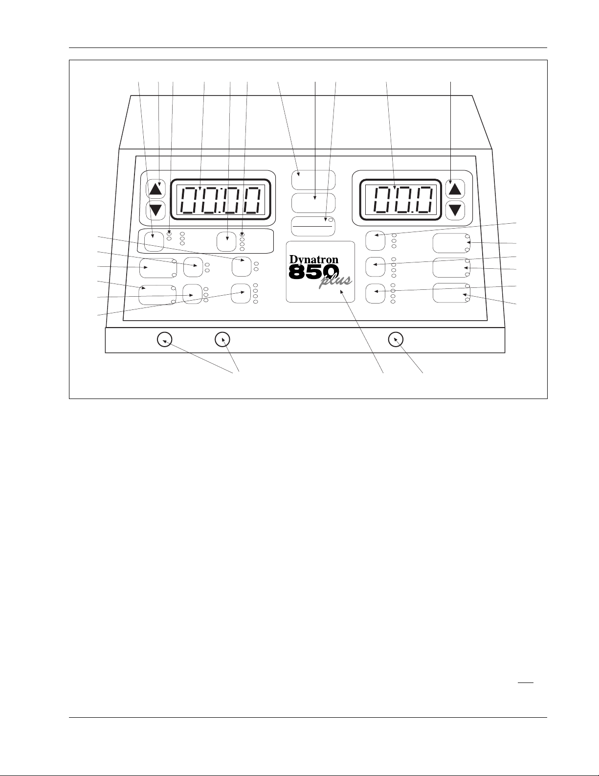
Dynatron 850plus Control Panel
Dynatron 850plus and Dynatron 550plus Physical Features
Before operating the Dynatron 850plus or Dynatron 550plus, acquaint yourself with the
control panel by reviewing the illustrations and descriptions on this and the following pages.
The numbered features in the diagrams correspond to the numbered descriptions. Before
administering treatment to a patient, read the sections later in this manual that provide
specific instructions for performing treatments, discussions of each modality, definitions of
the available options, along with contraindications, warnings, and precautions for all
modalities.
Note that some options use “toggle” keys for making selections. More specific instructions
for using toggle keys are provided later in this section.
General Selections:
1. START: Pressing this key starts the treatment timer, and treatment proceeds as set up.
2. STOP: Pressing this key during a treatment IMMEDIATELY stops the output and sets
the treatment time to zero for all modalities. Treatments may also be stopped by pressing
the button on the patient REMOTE STOP cable. You can also stop a treatment for one
treatment only by pressing and holding the Function
21
19
+
-
+
-
22
20
23
24
Installation & Features
7
Page 16
64
Dynatron® 850plus & 550plus
7589123 10 11
14
13
12
CH
PREMOD
IFC
HV
1
MICRO
2
Dynatronics
CH 1 CH 2
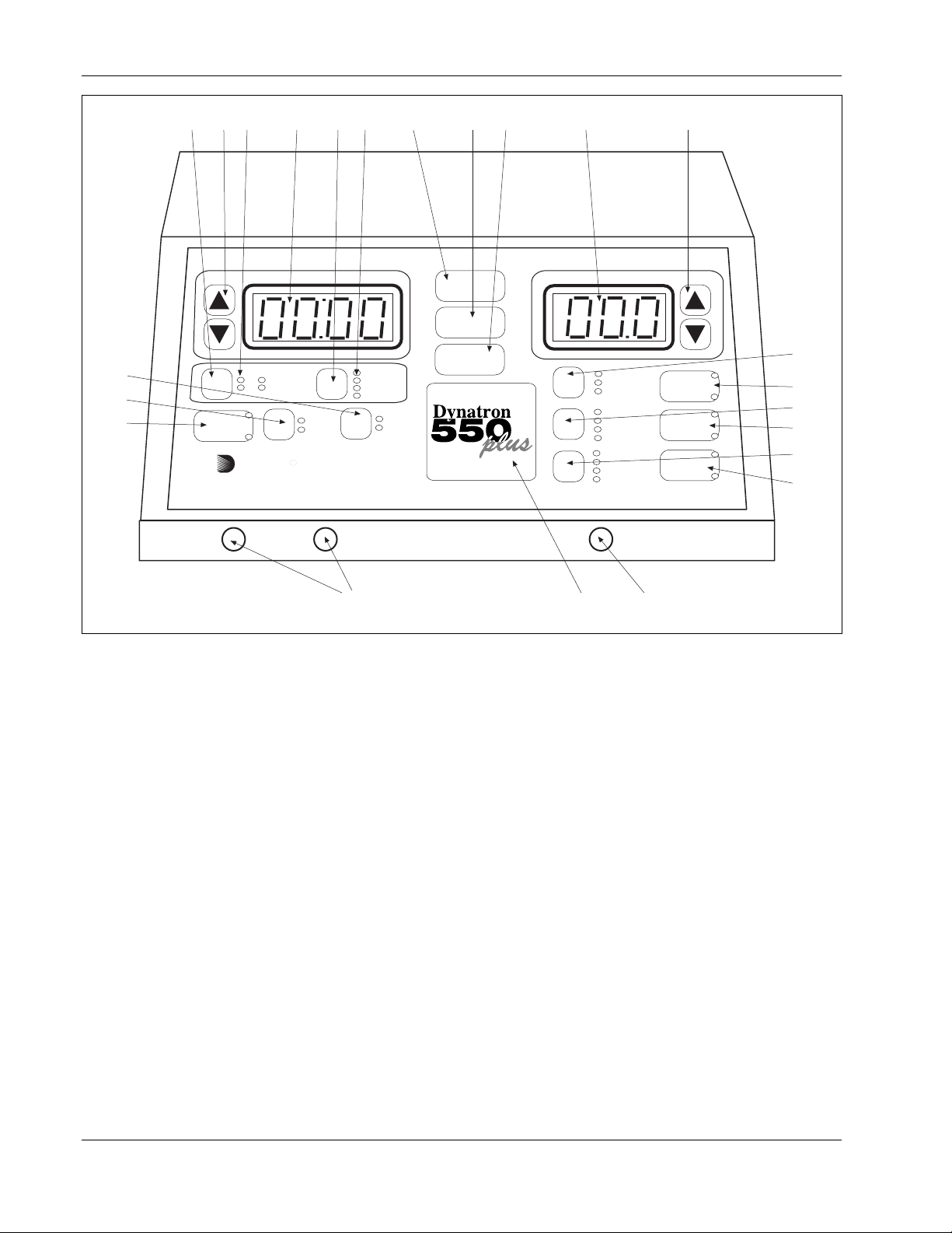
Dynatron 550plus Control Panel
key while you press the Stop key, or by reducing that channel’s treatment time to zero.
3. PAUSE/FUNCTION: This key is used in combination with other key presses for
accessing unique features including: select polarity (high volt and microcurrent), audio
volume control (microcurrent), and to stop one treatment only. Specific instructions for
using this key are provided later in this manual.
For Dynatron 850plus only: This key is also used to pause an ultrasound treatment. First
press the channel toggle (CH) to select SOUND, then press PAUSE/FUNCTION; the
ultrasound output is stopped, the treatment time is paused, and the light on the Pause key
is on. When this key is pressed again, the ultrasound treatment resumes and the light on
the Pause key is off. The PAUSE option is not available with the Dynatron 550plus since
that model does not offer ultrasound. NOTE: During a Combo treatment, only the
ultrasound output and the treatment timer are stopped when you press Pause; the stim
output continues.
4. TIME ARROW KEYS: These UP/DOWN arrow keys are used to increase/decrease the
treatment time or other parameter that is displayed in the Time display.
5. TIME DISPLAY: This display is used to show the treatment time for one treatment at a
time; the display shows treatment time for the selected channel (the selected channel is
indicated by the green LED—all other channels in use at the
TIME
HIGH
LOW
TIME
FREQ
RATE
WIDTH
TARGET
SWEEP
START
STOP
FUNCTION
TARGET
POWER-INTENSITY
NORMAL
CO-CONT
RECIP
10/10
10/30
10/50
CONT
.5 RAMP
1.0 RAMP
1.5 RAMP
2.0 RAMP
HV
261525
BIPHASIC
RUSSIAN
HI VOLT
MICRO
21
19
+
-
+
-
22
20
23
24
Installation & Features
8
Page 17

Dynatron® 850plus & 550plus
time will have yellow LEDs). The Time display can also display the pulse rate and width
for Russian and biphasic treatments, as well as the frequencies for interferential,
premodulated, and microcurrent treatments, and pulse rate for high volt. The treatment
parameters for any treatment in progress may be displayed at any time by first using the
channel toggle key to choose the desired channel then using the Time toggle key to select
the desired parameter (Time, Freq, Rate, Width).
6. CHANNEL TOGGLE KEY(CH): When a treatment is in progress, you can press this
key to choose an output channel and display the parameters for the treatment being
delivered by that channel. When a channel light is GREEN, the displays show the
settings for that channel. The available options depend on the modality selected. When
two or more treatments are in progress simultaneously, the toggle key is used to select the
channel you wish to view.
7. CHANNEL SELECTIONS: These lights indicate which output channels are currently in
use. A solid GREEN light indicates current is being delivered to that channel; the time,
intensity and other treatment parameters for that channel are also displayed. A solid
YELLOW light indicates a channel is in use and delivering current, but the time, intensity,
and treatment parameters are not displayed at this time (only one channel’s time and
intensity may be displayed at a time). Flashing green or flashing yellow indicate the “off”
segment of a biphasic, Russian or high volt treatment cycle. The channel’s intensity and
other treatment parameters may only be modified when it has a green indicator light. Press
the Channel Toggle key (CH) to select a channel to be viewed.
8. TIME TOGGLE KEY: Press this key to display various treatment parameters in the
Time display including Time (treatment time), Freq (frequency), Rate (pulse rate), and
Width (pulse width). Available options during a given treatment or treatment setup
depend on the modality selected.
9. TIME GROUP SELECTIONS: These lights indicate the parameters that are displayed
(one at a time) in the Time display. The default selection is the treatment time. Press the
Time toggle key to select the desired option (available options depend on the modality
selected). When a parameter is selected, its indicator light is green, its value is displayed
in the Time display above, and the time arrow keys may be used to change the value.
The device returns to the Time display after 10 seconds with no key presses.
10. POWER-INTENSITY DISPLAY: This display is used to display the treatment power (for
ultrasound) or intensity (for all other modalities) for the currently selected channel (the
selected channel is indicated by the green LED—all other channels in use at the time will
have yellow LEDs). Press the channel toggle key to select the desired channel to be
viewed.
11. POWER - INTENSITY ARROW KEYS: The arrow keys are used to increase/decrease
the intensity or power of one treatment. Changes made to power and intensity affect only
the currently selected channel (the selected channel is indicated by the green LED—all
other channels in use at the time will have yellow LEDs). Press the channel toggle key to
select the desired output channel. The arrow keys may then be used to change the
intensity or power for that channel.
Installation & Features
9
Page 18

Dynatron® 850plus & 550plus
IFC / Premod Selections:
12. IFC/PREMOD: Press this key once to begin setup of an interferential treatment (the IFC
LED is lighted); press this key twice to begin setup of a premodulated treatment (the
Premod LED is lighted). When you select IFC, both channels 1 and 2 are automatically
selected and the green LED lights for those two channels will be on. Connect two leads
to the output jacks for the channels that are selected. When you select PREMOD, a
single channel (CH1 or 2) is automatically selected and that channel’s green LED will be
on. Connect one lead to the output jack that corresponds to the channel indicated by the
green LED.
13. HIGH/LOW TOGGLE (used with interferential, premodulated and high volt): Press this
key one or more times to select the desired frequency range for interferential and
premodulated treatments or the pulse rate range for high volt treatments. The green LED
indicates the option selected. For example, press the High/Low toggle key once to select
High, press again to select Low, press again to select High/Low Alternating, and press
again to select High/Low Consecutive. For high volt treatments, you can select High or
Low only, but not both. During a treatment, the current sweeps through the range(s)
selected.
For interferential and premodulated, the HIGH frequency range is initially set at 80 to
150 Hz; and the LOW frequency range is 0 to 10 Hz. For high volt, the HIGH pulse rate
range is initially set at 80 to 120 Hz; and the LOW pulse rate range is 1 to 10 Hz. These
frequency ranges may be modified for every treatment, if desired and new default settings
for the device may also be saved. See treatment setup instructions later in this manual for
a complete description of the options that may be selected.
14. TARGET/SWEEP TOGGLE: This key is pressed to select either Target, Target Sweep,
or static treatment for an interferential treatment. The Target pad is used to locate the
exact treatment site (if the Target option is selected during an interferential treatment).
15. TARGET PAD: For use during interferential treatments when “Target” is selected.
Touch the TARGET pad at different points on the pad to reach the precise treatment site.
When you lift your finger from the Target pad, the selected point is locked until you
change it again. This patented feature is used to locate the specific treatment site in an
interferential treatment and to place the point of interference at that point.
Ultrasound Selections (DYNATRON 850plus ONLY—the ultrasound feature is
not available on the Dynatron 550plus):
16. SOUND/COMBO: Press this key once to begin setup of an ultrasound treatment (the
Sound LED on this key is lighted as well as the Sound LED in the channel indicator
area); press this key twice to begin setup of a combination treatment (the Combo LED is
lighted as well as the Sound LED and a single Channel LED in the channel indicator
area). When either of these options is chosen, the soundhead should first be plugged into
the ultrasound output jack on the side panel. For combination treatments, the special
combo lead wire should be attached to the output jack selected (see full instructions for
setting up a combination treatment later in this manual). In the COMBO mode, the
electrotherapy treatment is delivered through the soundhead and through a single
electrode which is placed on the patient. Only single-channel electrotherapy options are
available in the COMBO mode.
Installation & Features
10
Page 19

Dynatron® 850plus & 550plus
17. SOUND FREQUENCY TOGGLE: This key is pressed one or more times to select the
desired ultrasound frequency; 1 MHz, 2 MHz, or 3 MHz.
18. DUTY CYCLE TOGGLE: This key is pressed one or more times to select the desired
duty cycle for ultrasound treatment. Options are 10, 20, or 50 percent, or Continuous.
Russian / Biphasic / High Volt Selections:
19. BIPHASIC/RUSSIAN: Press this key once to begin setup of a biphasic treatment (the
Biphasic LED is lighted); press this key twice to begin setup of a Russian treatment (the
Russian LED is lighted). Biphasic and Russian treatments use a single channel (1 or 2)
when the Normal mode is selected; and a channel pair (1 and 2) when the Reciprocal or
Co-contraction mode is selected.
20. HIGH VOLT: Press this key to begin setup of a High Volt treatment (the Hi Volt LED is
lighted). The HV output channel is automatically selected (the LED for the channel
selected is GREEN). Connect the patient lead wire to the HV output jack.
HIGH VOLT POLARITY: To select or change the polarity of a high volt treatment, use
the HI VOLT key together with the FUNCTION key. Press and continue holding the
FUNCTION key while pressing the Hi Volt key one or more times to select positive only
(the “+” LED is lighted), negative polarity only (the “-” LED is lighted), or both (both
LEDs are lighted).
21. TREATMENT MODE TOGGLE (for biphasic and Russian treatments): Press this key
one or more times to select Normal, Co-Contraction, or Reciprocal contraction. The
output channel is automatically selected. When Normal is selected, one output jack only
is selected (1 or 2). When Co-contraction or Reciprocal is selected, channels 1 and 2 are
selected. Connect the patient lead wire(s) to the output jack(s) for the channel(s)
selected.
22. CONTRACTION/REST CYCLE TOGGLE (for Russian, biphasic, and high volt
treatments): Press this key one or more times to select the desired contraction/rest
(on/off) cycle . Available cycles include 10/10, 10/30, 10/50, and Continuous. The first
value indicates the on-time in seconds, and the second value indicates the off-time. For
example; 10/30 indicates the current is on (muscle is contracting) for 10 seconds, and
current is off (muscle is relaxed) for 30 seconds. With Continuous mode, current is
applied continuously with no off cycle. The continuous duty cycle is not recommended
for electrical muscle stimulation, but may be used for settings that are intended to effect
other results than a muscle contraction.
23. RAMP TIME TOGGLE (for Russian, biphasic, and high volt treatments): This key is
pressed to select the ramp time . The ramp time is applied before and after the “On”
segment of the cycle (it provides both a ramp up and a ramp down). Available ramp
times are .5, 1, 1.5, and 2 seconds.
NOTE: The High/Low option described previously under the Interferential/Premod options,
is also used for High Volt treatments (see item 13 above).
11
Installation & Features
Page 20
Dynatron® 850plus & 550plus
Microcurrent Selections:
24. MICRO: Press this key to begin setup of a microcurrent treatment. This key is also used
to turn the conductance tone off and on after a microcurrent treatment is started. When
MICRO is selected, Channel 1 is automatically selected for the default electrodes
treatment and the LED for that channel is lighted. For a microcurrent treatment setup
with electrodes, connect a patient lead wire to Channel 1 output jack. For a microcurrent
probes treatment, press the channel toggle key (CH) to select the MICRO channel
selection (Channel 1 LED will become yellow and MICRO will become green to indicate
the probes option is selected). Connect the microcurrent probe to the microcurrent output
jack on the left side panel of the device.
NOTE: Channel 1 is committed to the microcurrent output during a probes treatment as
well as during a treatment with electrodes, and is not available for use by any other
modality while any microcurrent treatment is in progress.
MICROCURRENT POLARITY: To select or change the polarity of a microcurrent
treatment, use the MICRO key together with the FUNCTION key. Press and continue
holding the FUNCTION key while pressing the MICRO key one or more times to select
positive only (the “+” LED is lighted), negative polarity only (the “-” LED is lighted), or
dual polarity (both LEDs are lighted).
25. OUTPUT JACK CHANNELS 1 and 2: These are the output jacks for delivering
interferential, premodulated, Russian, biphasic, and microcurrent treatments. Consult
treatment instructions later in this manual for appropriate channels and treatment setup
for each modality.
26. HIGH VOLT OUTPUT JACK HV. This is the output jack for delivering high volt
treatments. Consult treatment instructions later in this manual for high volt treatment
setup.
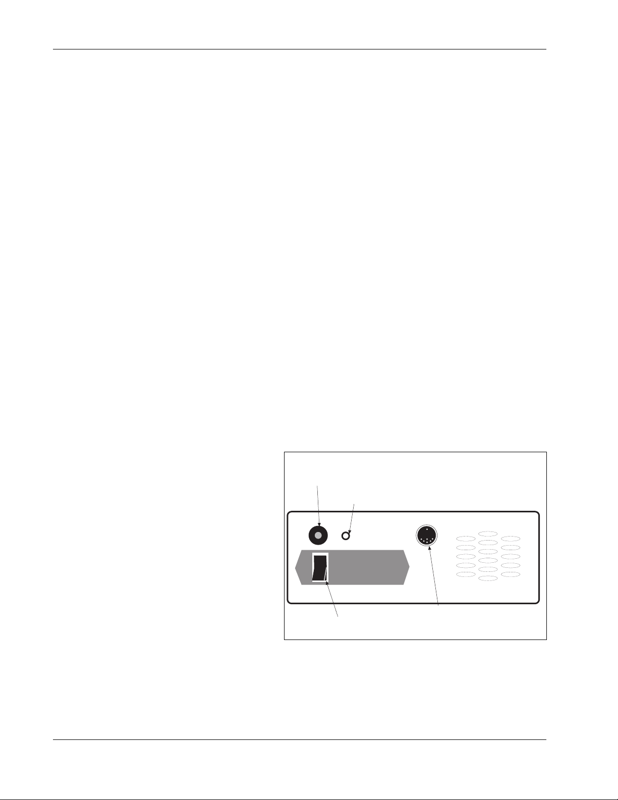
Dynatron 850plus and
550plus Back Panel:
27. POWER ON/OFF
28. Electrical Stim to Ultrasound
Input Jack (only on D850plus)
29. Jack for Optional Battery Pack
SWITCH: Located on the
back of the unit this switch
is labeled “1” and “0”. Set
the switch to “1” for ON;
set the switch to “0” for
OFF.
1
0
Batt. Input
28. STIM INPUT JACK FOR
COMBINATION
TREATMENTS: The special
lead wire for combination
treatments is plugged into this
jack for a combination
27. Power On/Off Switch
Dynatron 550plus and 850plus Back Panel
30. Patient Remote Stop Jack
treatment setup providing stim output through the ultrasound head. The special lead wire is
also plugged into the jack on the front of the device which has been selected for the specific
combo treatment. See combination treatment instructions later in this manual for detailed
information regarding combination treatment setup.
Installation & Features
12
Page 21
Dynatron® 850plus & 550plus
9. BATTERY: This jack may be used to supply power to the device using an optional
battery pack. More information about the optional battery operation is provided later in
this manual.
30. REMOTE STOP: A cord with a remote stop button is inserted in this jack. The remote
stop is controlled by the patient during unattended therapy to allow the patient to stop the
treatment at any time. When the button on the remote stop cable is pressed, output for all
stim modalities is stopped and the tone sounds briefly. During Combo treatments, both
sound and stim outputs are stopped.
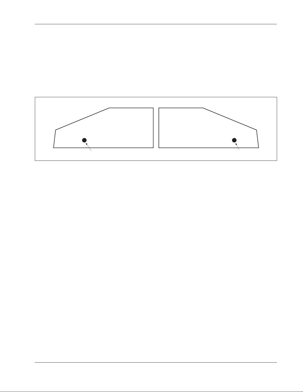
Right side of device (D850plus only)
Ultrasound Micro Probe
Left side of device
31. Ultrasound Ouput Jack
Side Panels
Dynatron 850plus and 550plus Side Panels:
31. ULTRASOUND OUTPUT JACK (DYNATRON 850plus ONLY—not available on the
Dynatron 550plus): The applicator soundhead plugs into this jack for ultrasound therapy.
32. MICROCURRENT OUTPUT JACK: The microcurrent probe plugs into this jack for
microcurrent probe therapy.
Instructions for Using Toggle Keys
Toggle keys are used to make selections from two or more options in a given area. Toggle
keys are pressed one or more times to make a desired selection. A GREEN light (LED) next
to the toggle key shows the option that has been selected. Pressing the toggle key one or
more times allows you to scan through the available options.
Each toggle key has unique capabilities. Most toggle keys allow only one selection. For
example, the Ramp toggle key requires you to select just one of the four ramp times
available. However, some toggle keys allow you to select two options. For example, in
interferential you can press the High/Low toggle key once to select High, press again to select
Low, and press again to select both High and Low.
The following is a list of all the toggle keys available with each modality:
32. Ouput Jack for Microcurrent Probe
13
Installation & Features
Page 22
Dynatron® 850plus & 550plus
IFC and Premod
• Target/Sweep (IFC only)
• High/Low Frequency Ranges
Russian and Biphasic Stim
• Treatment mode
• Contraction/Rest cycle
• Ramp Time
High Volt Stim
• Contraction/Rest cycle
• Ramp Time
• Polarity
• High/Low Pulse Rate Ranges
Microcurrent
• Microcurrent Polarity
• Channel toggle to select Micro or Channel 1 (during setup only)
All Modalities
• Time/Frequency/Rate/Width
• Channel Toggle (to view individual channels one at a time while treatments are in
progress
Ultrasound (Dynatron 850plus only)
• Ultrasound Frequency
• Ultrasound Duty Cycle
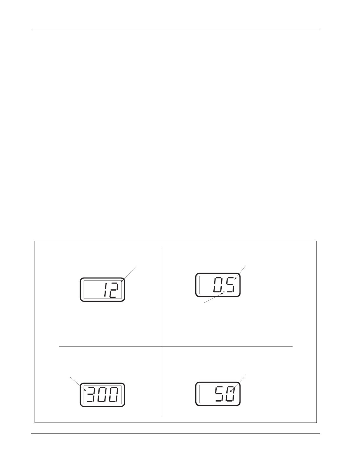
Stim Intensity Display
The intensity display is intended as an
incremental value only for the convenience
of the practitioner.
POWER-INTENSITY
Ultrasound Power Display
Ultrasound power is displayed, with the value
shown either in WATTS or W/cm2.
POWER-INTENSITY
Increasing the intensity does increase
current delivery. However, intensity and
current are not a 1:1 comparison. Actual
current delivered to the patient depends
upon the intensity setting and the current
density (affected by the size and
condition of the electrodes).
Microcurrent Intensity Display
Microcurrent intensity is displayed in
microamperes
POWER-INTENSITY
Examples of Power-Intensity displays for the Dynatron 850plus and 550plus.
A blinking decimal indicates the power is displayed
as WATTS. A steady (non-blinking) decimal
indicates WATTS/cm2. Pressing and holding the
PAUSE key changes the display from WATTS to
W/cm2 or reverse.
High Volt Intensity Display
High volt intensity is displayed in volts
POWER-INTENSITY
Installation & Features
14
Page 23
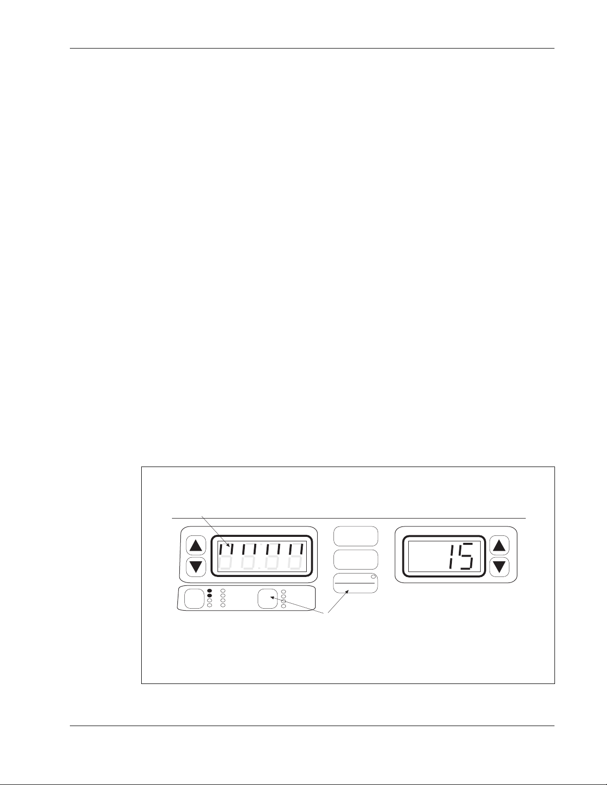
Time and Power Displays
The “Time” display and the “Power-Intensity” display can show the settings for only one
channel at a time. The Time and Power-Intensity settings displayed are for the channel with
the GREEN light only. Any other channel in use at that time will have a YELLOW light to
show it is active but its parameters are not currently displayed.
To view the settings for another
channel or output, press the channel
toggle key one or more times until
the light for the desired channel
becomes GREEN. The GREEN
light appears next to a different
channel or output each time you
press the toggle key, and the Time
and Power-Intensity displays change
to show the parameters currently in
effect for that channel.
The green and yellow channel lights
each will also appear solid (nonflashing) or flashing. A solid light
means current is being delivered to
the channel at this time (for example, during the ON cycle of the Russian stimulation
treatment). A flashing light means current is not being delivered to the channel at this time
(for example, during the OFF cycle of the Russian stimulation treatment).
Dynatron® 850plus & 550plus
When a channel is selected its parameters are displayed in
the Time and Power-Intensity displays, and treatment
parameters for that treatment may be modified.
Press the
channel toggle
key to select any
channel that is
currently in use.
The LED for the channel selected becomes GREEN and the
LEDs for all other active channels become YELLOW.
Channel Toggle Key
CH
TIME
HV 1
1
MICRO
2
SOUND
TIME
FREQ
RATE
WIDTH
CHANNEL / OUTPUT INDICATOR LIGHTS
GREEN Solid • You CAN see this channel’s parameters displayed on Time
and Power-Intensity displays.
• The channel IS delivering current.
GREEN Flashing • You CAN see this channel’s parameters displayed on Time
and Power-Intensity displays.
• The channel IS NOT delivering current.
YELLOW Solid • You CANNOT see this channel’s parameters displayed on
Time and Power-Intensity displays.
• The channel IS delivering current.
YELLOW Flashing • You CANNOT see this channel’s parameters displayed on
Time and Power-Intensity displays.
• The channel IS NOT delivering current.
Ultrasound Heads (Dynatron 850plus only)
The Dynatron 850plus features the new Dynatronics SmartHead™ ultrasound applicator
soundhead that has all calibration information self-contained. SmartHeads may be used
interchangeably with any 50 Series Plus model or the Dynatron 125 model with no need for
entering calibration numbers into the device.
15
Installation & Features
Page 24

Dynatron® 850plus & 550plus
Soundheads for the Dynatron 850plus come in 1 cm2, 2 cm2, 5 cm2, and 10 cm2 sizes. The
2
, 5 cm2, and 10 cm2 soundhead operate at 1, 2, and 3 MHz; while the 1 cm2 soundhead
2 cm
operates at 2 and 3 MHz. The soundheads are waterproof allowing ultrasound (not
combination) therapy to be administered in water, if desired.
Do not drop the soundhead nor allow it to strike a hard surface. Do not place soundheads
into ice water. Do not allow soundheads to repeatedly reach maximum head temperature.
All of these conditions can cause damage to the crystal. Any such damage is not covered by
the warranty.
For new or replacement soundheads, contact Dynatronics or your authorized Dynatronics
representative.
Microcurrent Probes (optional accessory)
The Dynatron 850plus and Dynatron 550plus devices offer optional probes for delivering
hands-on microcurrent treatment. The microcurrent probes can only be used for microcurrent
therapy. It is not possible to select the probe output nor to use the microcurrent probe to
deliver a probe treatment for interferential, premodulated, Russian, biphasic, or high volt
modes.
The setup includes an active probe along with either a ground probe or a ground electrode.
Use the end of a cotton swab (such as a Q-Tip
probe and the ground probes. Cut the end of the swab to a short length; the cotton must touch
the probe’s metal ring. Use water or a conductive electrolyte spray to wet the cotton swab
before treating.
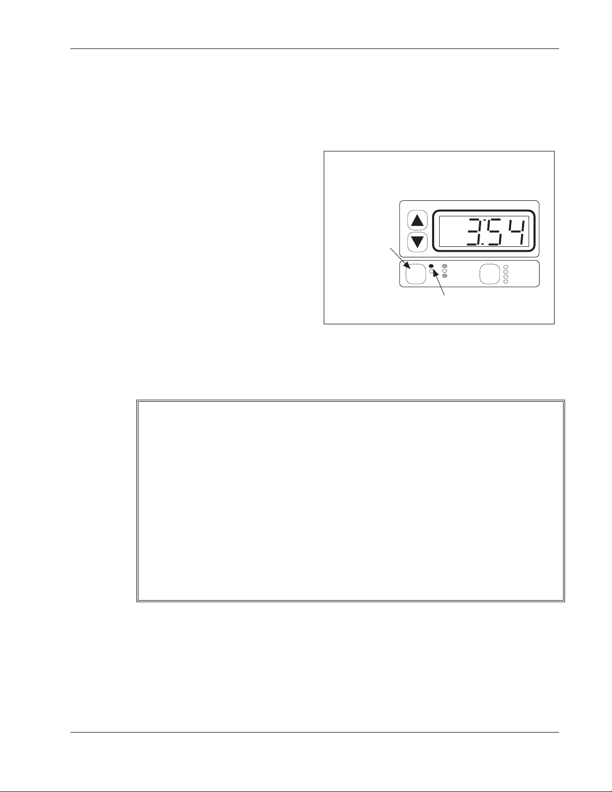
Active Probe: To deliver the current to the patient through the active probe, press and
release the button on the probe. Press and release the button again to stop the current. The
active probe should touch the patient’s skin at the treatment site, and the ground probe should
touch the patient’s skin elsewhere. This completes the circuit and delivers current to the
patient. You do not need to hold the button down. Once you have pressed and released the
button, the current is delivered until you press and release the button again to stop the current.
While you are delivering
current, the treatment
timer counts up in
seconds from zero. When
the current is stopped, the
timer returns to zero.
Press the button again to
commence the next time
sequence. Continue in
this way until treatment is
completed.
Ground Probe: The
ground probe is attached
directly to the banana pin
connector on the probe
cable. This probe is used to complete the circuit to allow flow of current through patient
tissue. The ground probe should touch the patient’s skin at any location away from the
treatment point. As an alternative, you may also use a ground electrode as explained below,
Press and release button
to start and to stop
current delivery during
treatment.
Cut the end off a cotton swab and insert it into
the tip of the cone. Saturate the cotton with
water or an electrolyte spray before treating.
Microcurrent Active Probe (optional accessory)
®) inserted into the ends of both the active
Installation & Features
16
Page 25

Dynatron® 850plus & 550plus
in place of the ground probe. This is particularly convenient when treating in several
different places around one point.
Ground Electrode: You can use an electrode in place of the ground probe. Just unplug the
ground probe from its cable, attach a banana-to-pin adapter to the cable, then attach an
electrode to the pin. Place the electrode on the patient at a site where it will not interfere with
placement of the active probe during treatment. The banana-to-pin adapter is an optional
accessory available from Dynatronics.
High Volt Probe (optional accessory)
An optional probe may be purchased which
allows you to deliver an attended high volt
treatment. The high volt probe is connected to
the dedicated high volt jack (HV) on the front
of the machine. The probe is used in
conjunction with a large dispersive electrode.
The high volt probe is used only for delivering
high volt therapy.
Complete setup and use instructions are
provided in this manual under the treatment
setup instructions for high volt.
High Volt Probe (optional accessory)
17
Installation & Features
Page 26

Dynatron® 850plus & 550plus
Quick Reference of Special Key Presses
The following is a brief list of special key presses available with this device. These options are explained in
detail where they apply in the treatment instructions later in this manual. NOTE: Where two keys are
required (ie, FUNCTION-STOP) you must press both keys simultaneously to achieve the result.
KEY PRESS RESULT DESCRIPTION
FUNCTION-STOP
FUNCTION-HI VOLT
FUNCTION-TIME CONDUCTANCE BAR GRAPH
FUNCTION-SOUND
SOUND-TARGET
SOUND-HI/LO keys
FUNCTION DISPLAY WATTS or W/cm2
FUNCTIONTARGET/SWEEP key
FUNCTION-MICRO
MICRO AUDIO TONE ON/OFF
FUNCTION-INTENSITY
UP & DOWN ARROW
KEYS
START SAVE NEW DEFAULT SETTINGS
STOP TREATMENT Stop one treatment
CHANGE HIGH VOLT POLARITY Change high volt polarity. Repeat to change again.
Press during IFC, premod or mcrocurrent treatment to view
conductance bar graph. Press TIME to return to normal display.
HEAD WARMING ON/OFF
ULTRASOUND COUPLING BAR
GRAPH
SOUNDHEAD TEMPERATURE BAR
GRAPH
TEST LEADS
CHANGE MICROCURRENT
POLARITY
CHANGE VOLUME
Set head warming feature to on (HD 1) or off (HD 0)
During an ultrasound treatment only, press to view the ultrasound
coupling bar graph. Press TIME to return to normal display.
During an ultrasound treatment, press to view the ultrasound head
temperature bar graph. Press TIME to return to normal display.
During ultrasound treatment hold for 2 seconds to change
ultrasound power display from w/cm2 to Watts or reverse.
Enter the Lead Test Function. Then press START to begin lead
test, and press STOP to exit the lead test function. NEVER DO
THIS WHILE ELECTRODES ARE ATTACHED TO PATIENT.
Change microcurrent polarity. Repeat to change again.
During a microcurrent treatment, turn audio tone on and off.
Change loudness of tone (during microcurrent treatment only)
Hold for 2 seconds to save defaults for current treatment.
The following key presses are applied only when powering up the device:
AT POWER ON, HOLD DOWN THE FOLLOWING KEYS WHILE THE DEVICE STARTS UP:
TARGET/SWEEP LEAD TEST MODE
START RESTORE FACTORY SETTINGS
FUNCTION ENTER CALIBRATION MODE
ULTRASOUND DUTY
CYCLE KEY
FUNCTION-TIME MODE
KEY
(Rev 1.02 and later)
FUNCTION-INTENSITY
DOWN ARROW
(Rev 1.02 and later)
ENTER SOUNDHEAD
PARAMETERS
DISABLE CONDUCTANCE BAR
GRAPH
DISABLE ULTRASOUND COUPLING
DETECTION
Press and hold on power up to enter Lead Test feature.
Press and hold on power up and wait for beep to restore factory
default settings.
Press and hold on power up to enter soundhead calibration mode
(for technicians only)
Press and hold on power up to enter soundhead parameter entry
mode (for technicians only)
Press and hold these keys at the same timeto disable the
conductance bar graph for treatment setup (the graph will still be
available for viewing after a treatment has started). After the
device starts up, select 1 (in the intensity screen) to turn the option
on and 0 to turn the option off.
Press and hold these keys to disable the ultrasound coupling
detection feature. The Time display will show the current setting
briefly: CP1=feature on, CP0=feature off. Repeat this step to
revert to the prior setting.
Installation & Features
18
Page 27

Dynatron® 850plus & 550plus
Section II
Operation and Treatment
Instructions
19
Operation & Treatment Instructions
Page 28

Dynatron® 850plus & 550plus
General Operating Instructions
Power On/Off
Press the power switch located on the rear panel of the unit. The self-diagnostic and calibration
function automatically occurs each time the unit is turned on. It is recommended that the unit
remain on throughout the day if it is used on a regular basis.
CAUTION: Never turn power on or off while the unit is connected to the patient.
Set intensity to minimum power before pressing START.
Basic Treatment Setup
Treatment setup is simple and fast with the Dynatron 850plus and 550plus. Each modality
has default settings that are automatically selected when you press a modality key. The basic
steps for setting up any treatment are:
1. Press a modality key once or twice to choose the desired modality (IFC, Premod,
Russian, Biphasic, High Volt, Micro, Sound, or Combo). The lighted LED on the key
indicates the modality chosen. The first available output channel(s) and default settings
for that modality are automatically selected. For ultrasound and combination treatments,
the soundhead must be connected to the device before selecting Sound or Combo.
2. Plug lead wires or probe cable into the appropriate jack(s) on the device for the
modality to be delivered. Observe which channels the device selected for this
treatment—channels are selected automatically by the device. Attach the electrodes
to the leads, and affix the electrodes to the patient. For unattended stim treatments, attach
the Remote Stop cable, and give the cable to the patient
3. Change any options desired using the toggle keys available for that modality.
4. Increase power or intensity. Current delivery to the patient starts when you increase
intensity. Only do this when you are ready to proceed with the treatment.
5. • For Target treatments only, locate the treatment site using the Target pad.
• For Russian / biphasic two-channel treatments, press Start or the channel toggle key after
setting the intensity for the first channel, then set the intensity for the second channel.
• For Combo treatments, set the parameters for the stim modality (or ultrasound), press
Start, then set parameters for ultrasound (or stim), then press Start again. You can select
the desired stim modality in this step by pressing the desired modality key after pressing
Combo.
6. Press Start. The treatment timer begins.
Operation & Treatment Instructions
20
Page 29
7. Administer treatment until the treatment time expires, or press STOP to stop all
treatments in progress at any time.
Each of the therapies you can deliver with the Dynatron 850plus and 550plus offers its own
default settings. To make your treatment setup even more convenient, the Dynatron 850plus
and 550plus allow you to change the defaults for each modality to your own most common
treatment selections. See “Setting Defaults” later in this manual.
The following pages provide more detailed setup instructions for each individual modality.
Before administering a treatment to a patient, be sure to read all treatment instructions
as well as contraindications, warnings, and precautions for that modality provided later
in this manual. Also, consult published literature for recommended application of these
modalities.
Conductance Bar Graph
This feature for models having software greater than Rev. 1.01 only (see Page 2).
During setup of an interferential or premodulated treatment, a conductance graph is
automatically displayed in the Time display while you set the treatment intensity. The graph
allows you to see whether conductance is good for that treatment setup and if current is being
delivered efficiently through the electrodes. The display reverts to the Time display when
you press any other key after setting the intensity. You may again view this conductance
graph at any time during an interferential, premodulated, or microcurrent treatment by
pressing FUNCTION-TIME. The conductance bar graph is not available for combination
treatments.
The bar graph uses the eight segments in the top half of the display, with eight lighted
segments indicating best conductance, and one lighted segment indicating poorest
conductance. In the illustration below, eight of the eight segments are lighted indicating good
conductance.
Eight lighted segments indicate conductance is good. If only
two or three segments are lighted, conductance is poor.
Dynatron® 850plus & 550plus
Conductance Bar Graph
CH
MICRO
3
SOUND
4
HV 1
1
HV 2
2
Conductance Bar Graph.
TIME
START
STOP
PAUSE
TIME
FREQ
RATE
WIDTH
During an IFC, Premodulated, or Microcurrent treatment, press
the FUNCTION and the TIME keys simultaneously to see the
conductance graph. Press TIME to return to the treatment
time display.
The graph is automatically displayed when the intensity is
increased during treatment setup for IFC and Premod.
FUNCTION
POWER-INTENSITY
Operation & Treatment Instructions
21
Page 30

Dynatron® 850plus & 550plus
If the graph indicates poor conductance, check to be sure leads and electrodes are in good
condition, that leads are fully plugged in and the entire surface of the electrode is making
contact with patient’s skin. Extremely dry skin can also be a cause of poor conductance. If
leads or electrodes are found to be worn, they should be replaced. Leads may be tested using
the Lead Test function described in the operator’s manual for this device. Guidelines for
replacing leads and electrodes are also provided in the operator’s manual.
When you no longer wish to view the conductance graph, press the TIME key to redisplay
the treatment time. NOTE: The treatment time counter does not stop, but continues counting
down when the graph is displayed.
Disable the Conductance Bar Graph. If you do not wish to see the conductance bar graph
automatically during the treatment setup, you can disable this function. Press and hold the
FUNCTION and TIME mode keys while powering the device on (NEVER TURN THE
DEVICE ON OR OFF WHILE LEADS ARE CONNECTED TO A PATIENT). When
the device completes starting up, the word “bar” appears in the TIME display, and “1”
appears in the Power/Intensity display. Use the intensity up/down arrow keys to change from
“1” to “0” (select 1 to turn this option on, select 0 to turn the option off). Press START after
making your selection. Once you have disabled the automatic portion of this option, the
device will default to the disabled mode each time the device is powered on. However, you
may still view the conductance graph at any time after the treatment has started as described
above. If you wish to reset the default to re-enable the bar graph to appear automatically
during treatment setup, again press and hold the FUNCTION and TIME mode keys while
powering the device on and select the desired setting.
“LEAD” Warning - No Patient Current
This feature for models having software greater than Rev. 1.01 only (see Page 2).
This added safety feature warns you if the device detects an “open” or incomplete circuit
during setup of an interferential treatment. An open can be due to a lead that is not plugged
in, an electrode that has fallen off or otherwise is not making contact with the patient, or
another reason that would cause an incomplete circuit. When this occurs, current is not being
delivered to the patient, and the condition must be corrected before continuing with treatment
setup.
"LEAD" ERROR - No Patient Current
No Patient Current. During an interferential treatment setup, if an open is detected, the “Lead” warning
is displayed along with the channel number that triggered the error.
When the device detects this condition during the treatment setup, it will beep and display
“LEAD” in the Time display, and will indicate in the Intensity display the number of the
channel that has triggered the error (for example, CH1), and you will be unable to increase
the intensity setting. If this error occurs, reduce the intensity for the channel indicated,
correct the condition, then return the intensity to the desired treatment level. In adjusting
Operation & Treatment Instructions
TIME
22
START
STOP
PAUSE
FUNCTION
POWER-INTENSITY
Page 31

Dynatron® 850plus & 550plus
intensity, always observe the warnings and precautions provided in the operator’s manual for
this device.
This error will not occur if the intensity is set below 11. The error condition can also be
detected during setup of premodulated treatments at the High frequency settings. The error
warning will also occur while a treatment is in progress under the same conditions described
above, but will only be displayed if the affected channel is currently selected for display.
Disable the Lead Warning. If you find the lead warning feature is too sensitive for your
treatment setup and is detecting conditions that are not truly open, you can adjust the
sensitivity. To do this, press and hold the IFC key while powering the device on (NEVER
TURN THE DEVICE ON OR OFF WHILE LEADS ARE CONNECTED TO A
PATIENT). The word “OPEN” is displayed in the Time display, and the default setting of
24 is displayed in the Intensity display. A lower number provides reduced sensitivity. At a
zero setting no error will be displayed. Use the up/down arrow keys to change the setting,
then press Start to exit this mode. The setting you select will remain as the default for the
device until you change it.
23
Operation & Treatment Instructions
Page 32

Dynatron® 850plus & 550plus
Interferential / Premodulated Instructions
WARNING
• NEVER turn the power on or off while the unit is connected to the patient.
• Always give the Remote Stop cable to the patient prior to the treatment.
• Always STOP a treatment before removing or attaching electrodes or leads. Leads and
electrodes must only be applied to the patient before a treatment is started.
• Never use worn or damaged leads or electrodes as these may result in injury to the patient.
• See the contraindications, warnings, and precautions for interferential and premodulated
treatments in this manual before administering a treatment to a patient.
• Additional warning from the Canadian Health and Welfare Department, Health Protection
Branch: WARNING: Thoracic applications are contraindicated. Cardiac fibrillation may
occur if output current is 50 mA RMS or greater for any output circuit. (For use in Canada
and Japan, this device is limited to 50mA output.)
An interferential treatment uses both channels 1 and 2 and four electrodes. The device will
automatically select these channels when you select IFC. A premodulated treatment uses one
channel and two electrodes. The device will automatically select the first available channel (1
or 2) when you select PREMOD. If desired, you may set up two premod treatments using
available channels.
Basic Interferential / Premod Setup
1. Choose IFC or PREMOD.
• Plug the patient lead(s) into the output jack(s) for the channel(s) selected.
• Attach electrodes to patient at treatment site.
• Give the remote stop cable to the patient.
2. Set the treatment TIME.
3. (Optional) CUSTOMIZE FREQUENCIES now.
4. Choose HIGH, LOW, or HIGH/LOW alternating, or HIGH/LOW consecutive.
5. Choose TARGET, SWEEP or STATIC (for Interferential treatments only)
6. Increase INTENSITY (patient will feel the current).
7. Press START.
8. Press STOP if you need to stop a treatment before its time has expired (stops all current
treatments).
IFC & PREMOD - Treatment Instructions
24
Page 33

Dynatron® 850plus & 550plus
NOTE: Prior to increasing intensity, electrodes must be placed on the patient and the lead(s)
attached to the device. Plug the lead(s) into the channel(s) the device selects for this
treatment. Give the remote stop cable to the patient. Consult
published sources for electrode placements, treatment settings, and treatment times. Make
sure electrodes make good contact with the patient’s skin over the entire surface area of the
electrode. Improper electrode contact may result in patient injury.
Detailed Interferential / Premodulated Setup
1. Press the IFC / PREMOD key once to choose IFC (interferential), or press this key twice
to choose PREMOD (premodulated).
When you choose IFC, channels 1 and 2 are automatically selected. When you choose
PREMOD, the first available channel is selected; make sure the patient lead is plugged
into the correct jack for the channel selected. The default settings for the modality are
automatically selected too, and if you wish to use the default settings, you can now
increase the intensity to the desired level, then press START.
If you wish to change the treatment settings, do the following steps.
2. Set TIME.
The default treatment time is displayed. Use the Time arrow keys to increase or decrease
the treatment time.
3. Customize the FREQUENCY settings (optional).
The default High and Low frequency settings are:
The HIGH range is 80 to 150 Hz.
The LOW range is 0 to 10 Hz.
These ranges may be changed for a single treatment if desired, or new default
settings may also be saved to apply to all future treatment setups. The same default
setting applies to both interferential and premodulated treatments.
You may change the frequency settings for the range you plan to select for this treatment,
if desired (see illustration next page). Each premodulated treatment may have its own
frequency settings. After you press START to begin the treatment, frequency settings
will remain in effect for the duration of the treatment. If you save defaults during this
treatment, the new frequency settings you have entered become the defaults for this
modality. However, if you do not save the new settings, the unit will return to the current
default settings for the next treatment.
To modify the frequency during setup, first, press the toggle key and select either the
HIGH or the LOW frequency range. Next press the TIME toggle key to select FREQ.
The FREQ light under the TIME display becomes green and you will see the current
frequency range settings displayed in the Time and the Intensity displays as shown in the
diagram on the following page. With FREQ selected and either the HIGH or LOW range
selected, you may use the up/down arrow keys to change the upper and lower limits of
the range chosen. If you set both displays to the same value, the treatment will be
delivered at that single frequency rather than sweep through a frequency range.
When you are finished setting the frequencies, press the Time toggle key to return to the
Time display. After 10 seconds with no key presses, the Time display automatically
returns.
25
Treatment Instructions - IFC & PREMOD
Page 34
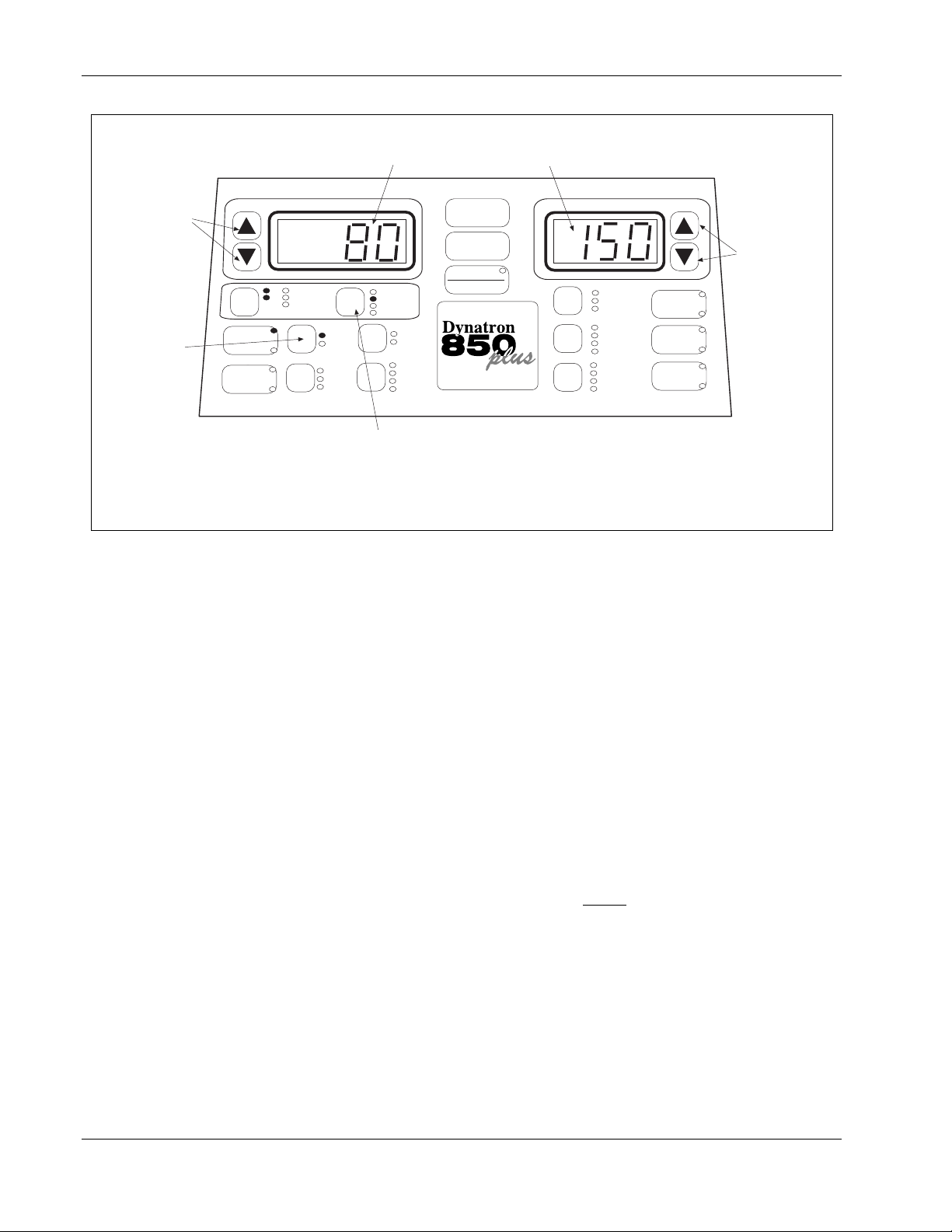
Dynatron® 850plus & 550plus
The lower limit in the sweep range is shown
here. In this example, this is the lower limit
of the default HIGH frequency range.
The upper limit of the range is shown here. In
this example, this is the upper limit of the
default HIGH frequency range.
Use these arrow
keys to change
the lower limit of
the range.
Use this toggle key
to select the HIGH
or LOW range.
TIME
HV
1
MICRO
2
CH
PREMOD
SOUND
COMBO
Press this toggle key to select FREQ. The "Time" and "Intensity" displays then show the lower
and upper settings for the range you have selected (High or Low). In the example above, 80
Hz is the lower limit for the range and 150 Hz is the higher limit for the range. Use the arrow
keys beside each display to change either or both of these frequencies, if desired.
NOTE: By setting both displays to the same value, you can deliver a treatment at a single
frequency rather than sweep through a range of frequencies. For example, set both the upper
and the lower limits at "100" for a 100 Hz treatment.
SOUND
IFC
CH 1 CH 2
HIGH
LOW
1 MHz
2 MHz
3 MHz
TIME
FREQ
RATE
WIDTH
TARGET
SWEEP
10%
20%
50%
CONT
START
STOP
PAUSE
FUNCTION
TARGET
Modify frequency ranges in Interferential or Premodulated treatments.
4. Choose HIGH, LOW, HIGH/LOW alternating, or HIGH/LOW consecutive.
Press the HIGH/LOW toggle key one or more times to select the high frequency range,
the low frequency range, or both. The lights next to the toggle key show what you have
selected. Select from the following options:
a. High only. Toggle until only the High light is on.
b. Low only. Toggle until only the Low light is on.
c. High/Low Alternating. Toggle until both High and Low lights are on, only one of
these is flashing. When the treatment has started, the device alternates between the
two modes at intervals of approximately 30 seconds each beginning with Low.
d. High/Low Consecutive. Toggle again; both High and Low are flashing. During the
first half of the treatment time the High frequency range is delivered. During the
second half of the treatment time the Low frequency range is delivered. NOTE:
Make any desired changes to the treatment time before
Treatment time changes made after selecting Consecutive will cause the treatment to
revert to an alternating treatment (option c. above).
Once the treatment has started, the frequency range (High or Low) being delivered at a
given time is indicated by the flashing High or Low light.
5. Increase INTENSITY.
Set the intensity by pressing the Intensity UP arrow key. When you increase intensity,
current to the patient begins. Intensity can be decreased by pressing the Down arrow key.
NOTE: For devices having software greater than Rev. 1.01, the conductance bar graph is
POWER-INTENSITY
NORMAL
CO-CONT
RECIP
10/10
10/30
10/50
CONT
.5 RAMP
1.0 RAMP
1.5 RAMP
2.0 RAMP
HV
Use these arrow
keys to change
the upper limit of
the range.
BIPHASIC
RUSSIAN
+
HI VOLT
-
+
MICRO
-
selecting Consecutive.
IFC & PREMOD - Treatment Instructions
26
Page 35

Dynatron® 850plus & 550plus
displayed while intensity is being set or changed. See page 21 for a complete explanation
of the conductance bar graph.
Before selecting the intensity setting for an individual patient, see “Electrotherapy Usage
Cautions” in this manual for recommended intensity settings. Also see the section of this
manual entitled “Contraindications, Warnings, and Precautions” for specific precautions
when treating any conditions contributing to loss of sensation, or any time the patient
cannot feel the electrical stimulation.
6. Choose TARGET, SWEEP, or STATIC (for interferential only).
TARGET. Press the toggle key to select this option if it is not already selected. The
patented Target feature allows you to pinpoint the treatment site to deliver the full
interferential current where it is needed. NOTE: You must set the intensity before using
the Target Pad so the patient will be able to tell you when the treatment site is found.
Also remember, an injured area will often be more sensitive to the current delivered.
Therefore, an intensity setting that is comfortable to the patient at first may feel
uncomfortable when the treatment site is found using the Target pad. If necessary,
reduce the intensity to the patient’s comfort level.
SWEEP. Press the toggle key one or more times to select this option. This option uses
Dynatronics’ patented Target feature to automatically move the point of interference in a
somewhat spiral fashion covering 75 to 80 percent of the area within the electrodes. This
allows you to bathe a more general area with the interferential current while retaining the
full interferential beat.
STATIC. This option is applied when neither Target nor Sweep are selected. Press the
toggle key one or more times to unselect those options (the LEDs will both be off). The
treatment becomes a STATIC treatment. In other words, it simply allows the two
currents to take a path of least resistance and intersect at a natural point within the
electrodes.
7. Press START.
When you press start, the treatment timer begins counting down and the treatment
proceeds. If you fail to set the intensity before pressing START, the intensity display
will begin flashing, and you will be unable to start the treatment until you set the
intensity.
SAVE DEFAULTS. If the treatment you have just set up is a common treatment setup
you use, you can save the treatment parameters as new defaults for your own machine.
After setting up the treatment, simply press and hold the START key for two seconds. At
the end of two seconds, you will hear a beep indicating the treatment parameters have
been saved. The next time you select that modality, these parameters are selected
automatically.
8. MODIFY settings.
While the treatment is in progress, you can modify any of the treatment parameters, if
desired. Note: If you change the treatment time during a consecutive High/Low treatment,
the treatment will revert to alternating High/Low.
27
Treatment Instructions - IFC & PREMOD
Page 36

Dynatron® 850plus & 550plus
• Use the High/Low toggle key to select a different frequency option (High, Low,
or High/Low alternating only. High/Low consecutive is only available during
treatment setup).
• Use the Target/Sweep toggle key to change this option (IFC only)
• Use the Time arrow keys to increase or decrease the treatment time.
• Use the Intensity arrow keys to increase or decrease the intensity.
• Relocate the treatment site by touching the Target pad at any time during the
treatment (only when Target is selected).
9. Press STOP if it is necessary to stop a treatment before time has expired.
When the treatment time has elapsed, the current to the patient stops and a tone sounds
notifying you of the treatment end. Treatments in progress may be stopped at any time
using one of the following methods.
STOP: Press this key to stop all treatments at all channels.
REMOTE STOP: During “unattended therapy,” a patient stop button is provided to
allow the patient to stop treatment. The remote cord should be plugged into the machine
prior to starting the treatment. When the remote stop button is pressed, all output from
the device is stopped, time is set to zero, and a tone sounds briefly.
STOP ONE TREATMENT ONLY: If you have more than one treatment in progress,
you can stop one treatment by either of the following methods. First, press the channel
toggle key to select the channel to be stopped (that channel’s light is green when
selected).
FUNCTION-STOP. Press and hold the FUNCTION key and press STOP.
REDUCE THE TREATMENT TIME TO ZERO. Press the Time down arrow
until the Time display reaches zero. The device beeps when the time reaches
zero.
The output at the selected channel is stopped, and the device then displays the parameters
for the next treatment that remains in progress (if any).
Interferential / Premodulated Default Settings
The following default settings are set by the manufacturer and are selected when you select
IFC or PREMOD. You may change these defaults to your own preferred settings. See
“Setting Defaults” in this manual.
Interferential
• High frequency range
• Target
• Time: 10 minutes
Premodulated
• High frequency range
• Time: 10 minutes
IFC & PREMOD - Treatment Instructions
28
Page 37

Dynatron® 850plus & 550plus
Biphasic / Russian Instructions
WARNING
• NEVER turn the power on or off while the unit is connected to the patient.
• Always give the Remote Stop device to the patient prior to the treatment.
• Always STOP a treatment before removing or attaching electrodes or leads. Leads and
electrodes must only be applied to the patient before a treatment is started.
• Never use worn or damaged leads or electrodes as these may result in injury to the
patient.
• See “Contraindications, Warnings, and Precautions” in this manual before administering a
treatment to a patient.
In the Russian and Biphasic Stimulation modes the output of the device is a pulsed sinusoidal
wave. The Dynatron 850plus and 550plus allow the operator to choose a muscle
contraction/relaxation cycle that is most suited for the individual patient and for the desired
treatment. When the cycle required is chosen, each muscle-stimulating burst is followed by a
relaxation (rest) cycle. See “Russian/Biphasic Parameters” in this manual for further
discussion of pulse rate and width, and illustrations showing the segments of the Russian
Stimulation cycle and the Biphasic Stimulation cycle.
The Dynatron 850plus and 550plus provide three modes of treatment in Russian and Biphasic
Stimulation: Normal, Reciprocal and Co-Contraction. You will need to decide which mode
is to be used and attach the appropriate number of leads needed when setting up the
treatment. You may set up two Biphasic or two Russian treatments with Normal mode. You
may not set up one Russian and one Biphasic at the same time as both channels share
frequency settings during these treatments.
NORMAL: Use one channel with one lead wire (two electrodes), place the electrodes so as
to treat through the muscle. The contraction/relaxation cycle is selected from an option list of
10/10, 10/30, 10/50, and Continuous (there is no rest cycle with Continuous). Each time
period is indicated in seconds. For example, 10/30 indicates 10 seconds of stimulation with
30 seconds of relaxation. The continuous duty cycle is not recommended for electrical
muscle stimulation, but may be used for settings that are intended to effect results other than a
muscle contraction.
CO-CONTRACTION: Use two channels and two lead wires (four-electrodes) for this
treatment. Each pair of electrodes is placed over a different muscle group. This treatment
fires the two muscle groups simultaneously—contraction and rest cycles for both treatment
areas occur at the same time
. Two channels are required (1 and 2).
RECIPROCAL: Use two channels and two lead wires (four electrodes) for this treatment.
The reciprocal muscle stimulation fires two muscle groups (such as reciprocal
flexors/extensors) one after the other. For example, with a duty cycle of 10/30, the device
Treatment Instructions - RUSSIAN & BIPHASIC
29
Page 38

Dynatron® 850plus & 550plus
would deliver stimulation for 10 seconds to the first muscle, followed by 10 seconds of
stimulation to the reciprocal muscle. The 30-second rest time follows each stimulation. The
timing of the two cycles will overlap (the first muscle group is stimulated after a 30-second
rest, even though the second muscle group is 20 seconds into its rest cycle). The Continuous
contraction cycle is not available for Reciprocal treatments. Two channels are required (1
and 2).
Basic Biphasic / Russian Setup
1. Choose BIPHASIC or RUSSIAN.
2. Choose the TREATMENT MODE (Normal, Co-contraction, Reciprocal).
• Plug the patient lead(s) into the output jack(s) for the channel(s) selected.
• Give the remote stop cable to the patient.
3. Choose the CONTRACTION/REST times.
4. Choose the RAMP setting.
5. Change the treatment TIME, if desired.
6. Change the PULSE WIDTH and/or PULSE RATE, if desired.
7. Raise the INTENSITY to the desired level.
8. For co-contraction or reciprocal treatments, toggle to the SECOND CHANNEL and set
the INTENSITY for this channel.
9. Press START.
10. Press STOP if you need to stop a treatment before its time has expired (stops all current
treatments).
Detailed Biphasic / Russian Setup
If you do not understand the terms contraction, rest, ramp time, pulse width, or pulse rate, consult
the diagrams in the section of this manual entitled “Biphasic / Russian Parameters.”
1. Press the BIPHASIC / RUSSIAN key once to choose BIPHASIC, or press this key twice
to choose RUSSIAN.
When you select this modality, the default settings are automatically selected. If you
wish to use the default settings, you can now increase intensity to the desired level, then
press START. If you wish to change the treatment settings, do the following:
2. Choose the TREATMENT MODE (Normal, Co-contraction, Reciprocal).
Press the toggle key one or more times to select Normal, Co-contraction or Reciprocal
contractions (these options are explained at the start of this section). Connect the patient
lead wire(s) to the channel(s) selected.
RUSSIAN & BIPHASIC - Treatment Instructions
30
Page 39

Dynatron® 850plus & 550plus
3. Choose the CONTRACTION/REST cycle times.
Press the toggle key one or more times to select contraction/rest cycle times. Available
options include 10/10, 10/30, 10/50 and Continuous. The setting of 10/30, for example,
means a 10-second contraction time followed by a 30-second rest time. Note that you
may not select Continuous cycle for a Reciprocal treatment. The Continuous duty cycle
is not recommended for electrical muscle stimulation, but may be used for settings that
are intended to effect results other than a muscle contraction.
4. Choose the RAMP setting (does not affect Continuous treatments).
Press the toggle key one or more times to select the desired ramp time. Available options
include .5, 1.0, 1.5, and 2.0 seconds. The ramp time is applied to both the start and to the
end of the contraction time, and the ramp time is in addition to the contraction time itself.
5. Change the treatment TIME, if desired.
The default time is displayed. Use the Time arrow keys to increase or decrease the
treatment time.
6. Change the PULSE WIDTH and/or PULSE RATE, if desired.
Two Normal treatments will share whatever frequencies you set for the first channel.
Keep this in mind if you plan to set up two biphasic or Russian treatments. Also note
that the pulse width and pulse rate may only be changed when setting up the first
channel in a two-channel treatment.
Press the Time toggle key to select either pulse width or pulse rate. The indicator lights
next to the Time toggle key show you which option is currently selected. When either
pulse width or pulse rate is selected, the current setting for that option is displayed in the
Time display (only). You can change the setting by using the Time up/down arrow keys.
You can press the toggle key again to return to the Time display, if desired. However, if
you make no key presses for 10 seconds, the display automatically returns to the Time
display.
The ranges and default settings for pulse width and pulse rate are listed later in this
section. See “Biphasic / Russian Default Settings.”
7. Raise the INTENSITY to the desired level.
Set the intensity by pressing the Intensity UP arrow key. When you increase intensity,
current to the patient begins. Intensity can be decreased by pressing the down arrow key.
Before selecting the intensity setting for an individual patient, see “Electrotherapy Usage
Cautions” for recommended intensity settings later in this manual. Also see the section
of this manual entitled “Contraindications, Warnings, and Precautions” for specific
precautions when treating any conditions contributing to loss of sensation, or any time
the patient cannot feel the electrical stimulation.
The intensity, pulse rate, and pulse width must all be considered together when setting up
the treatment as all three factors affect patient comfort. It may be necessary to adjust one
or more of these parameters somewhat after the initial settings are selected to find the
best settings for a given treatment and patient.
Treatment Instructions - RUSSIAN & BIPHASIC
31
Page 40

Dynatron® 850plus & 550plus
8. For co-contraction or reciprocal treatments, select the SECOND CHANNEL and set the
INTENSITY for this channel.
Intensity is set for each channel separately. Press the Channel Toggle key to select the
second channel. When you are setting intensity, only the channel with the solid green
light is affected. If you wish to select a channel which has a YELLOW-colored light,
press the Channel Toggle key until that channels’ LED is selected (green).
You may only modify the parameters for the channel that is currently selected (indicated
by the green LED). A green flashing LED indicates that the selected channel is in the
rest segment of its cycle. If the light is green and flashing when you begin to modify
intensity, pulse rate or pulse width, current is ramped up to treatment level for that
channel so those parameters may be modified.
9. Press START.
When you press start, the treatment timer begins counting down. If you fail to set the
intensity before pressing START, the intensity display will begin flashing, and you will
be unable to start the treatment until you set the intensity. For Reciprocal and Cocontraction treatments, you must set the intensity for each channel separately.
SAVE DEFAULTS. If the treatment you have just set up is the most common Biphasic
or Russian treatment setup you use, you can save the treatment parameters as new
defaults for your own machine. After setting up the treatment, simply press and hold the
START key for two seconds. At the end of two seconds, you will hear a beep indicating
the treatment parameters have been saved. The next time you select this modality, these
parameters are selected automatically.
10. MODIFY settings.
While the treatment is in progress, you can modify the treatment parameters. You will
need to observe the channel indicator lights when modifying a treatment.
• When a channel’s light is green, the current treatment parameters for that channel are
displayed. Any changes you make to the parameters will affect the channel with the
green light only.
• When a channel’s light is yellow, the channel is still active, but its parameters are not
being displayed and it may not be modified until it is selected. You must first press
the toggle key to select the channel—its light will then become green and
modifications are allowed.
• When a light is solid (any color), this indicates the channel is in the CONTRACTION
segment of the cycle and current is being delivered to that channel. When a light is
flashing, this indicates the channel is in the REST segment of the cycle and current is
not being delivered at this time. If you select a channel for modification while its
light is flashing, the device will ramp the current up on that channel before allowing
you to make modifications. When the light changes from flashing green to solid
green, you will be able to modify the settings for the channel.
RUSSIAN & BIPHASIC - Treatment Instructions
32
Page 41

Dynatron® 850plus & 550plus
During a Biphasic or Russian treatment you may make the following modifications:
• Use the toggle keys to select a different contraction/rest cycle.
• Use the toggle keys to select a different ramp time.
• Use the Time arrow keys to increase or decrease the treatment time.
• Use the Intensity arrow keys to increase or decrease the intensity (separately for each
channel).
• Use the Time toggle key to select the Pulse Rate or Width, then use the Time
up/down arrow keys to change the pulse rate (not available for Reciprocal treatments
nor when two “Normal” treatments are running simultaneously).
11. Press STOP if it is necessary to end the treatment before the treatment time has expired.
When the treatment time has elapsed, current to the patient is stopped and a tone sounds
notifying you of the treatment end. Treatments in progress may be stopped at any time
using one of the following methods.
STOP: Press this key to stop treatment at all channels.
REMOTE STOP: During “unattended therapy,” a patient stop button is provided to
allow the patient to stop treatment. The remote cord should be plugged into the machine
prior to starting the treatment. When the remote stop button is pressed, all output from
the device is stopped, time is set to zero, and a tone sounds briefly.
STOP ONE TREATMENT ONLY: If you have more than one treatment in progress,
you can stop one treatment by either of the following methods. First, press the channel
toggle key to select the channel to be stopped (that channel’s light is green when
selected).
FUNCTION-STOP. Press and hold the FUNCTION key and press STOP.
REDUCE THE TREATMENT TIME TO ZERO. Press the Time down arrow
until the Time display reaches zero. The device beeps when the time reaches
zero.
The output at the selected channel is stopped, and the device then displays the parameters
for the next treatment that remains in progress (if any).
Biphasic / Russian Default Settings
The following default settings are set by the manufacturer and are selected when you select
Biphasic or Russian. You may change these defaults to your own preferred settings. See
“Setting Defaults” in this manual.
• Normal mode
• 10/30 contraction/rest times
• Treatment time: 10 minutes
• Ramp up and down time: .5 sec.
Treatment Instructions - RUSSIAN & BIPHASIC
33
Page 42

Dynatron® 850plus & 550plus
Biphasic Stimulation:
Default Setting Valid Range
Pulse Rate 50 Pulses per second 1 to 500
Pulse Width 200 µSec 50 to 400 µSec
Russian Stimulation:
Default Setting Valid Range
Pulse Rate 50 Pulses per second 1 to 500 (depends on Pulse Width)
Pulse Width 10 mSec .4 to 50 mSec
RUSSIAN & BIPHASIC - Treatment Instructions
34
Page 43

Dynatron® 850plus & 550plus
High Volt Instructions
WARNING
• NEVER turn the power on or off while the unit is connected to the patient.
• Always give the Remote Stop device to the patient prior to the treatment.
• Always STOP a treatment before removing or attaching electrodes or leads. Leads and
electrodes must only be applied to the patient before a treatment is started.
• Never use worn or damaged leads or electrodes as these may result in injury to the
patient.
• See “Contraindications, Warnings, and Precautions” in this manual before administering a
treatment to a patient.
High volt electrical stimulation is a pulsed DC current with pulse widths in the microsecond
range and pulse rates ranging from 1 to 200 Hz, with a peak amplitude of up to 1.0 amp. The
Dynatron 850plus and 550plus deliver high volt utilizing a twin-peak monophasic waveform.
High volt treatments with the Dynatron
550plus and 850plus may be delivered using
electrodes or an optional hand-held probe.
The device provides a dedicated channel for
high volt treatment (HV). This channel is
( – )
used to deliver high volt treatments only.
The device’s other output channels (CH1-2)
remain available for other stim treatments
simultaneously with the high volt treatment.
Dispersive electrode:
Attach to NEGATIVE
lead output.
Active electrode:
Attach to POSITIVE
lead output.
Set Up High Volt Treatment with
Electrodes
DOUBLE
OUTPUT LEAD:
Connect to "HV"
channel
This treatment setup utilizes a double-output
High Volt Electrode Setup
lead with two electrodes; an active and a
dispersive electrode. The size of the dispersive electrode is recommended to be double the
area of the active electrode. If desired, the active output of the lead may be bifurcated to
attach additional active electrodes; however, the combined total area of the active electrodes
should be no more than half the area of the single passive electrode. These setups are
illustrated on this page and the following page.
( + )
35
Treatment Instructions - HIGH VOLT
Page 44

Dynatron® 850plus & 550plus
Press the HI VOLT key; the device
automatically selects the high volt
channel (HV). Connect one lead with
two output connections to the HV
channel. It is best to use a lead that is
marked to show polarity. The active
electrode is connected to the positive
output. The dispersive electrode is
connected to the output end that is
marked negative. Ensure electrodes
are attached correctly to ensure the
polarity selected on the front panel of
the device is delivered
If desired, a bifurcated lead extension
may be attached to the positive (active)
end of the lead wire, allowing two active
High volt electrodes with bifurcated active lead.
electrodes to be used. In this case, be sure the dispersive electrode is at least twice the size
(in area) of the combined sizes of the active electrodes. The bifurcated lead wire extension is
an optional accessory available through your Dynatronics dealer.
During the treatment current flows in one direction between the active and dispersive
electrodes. Changing the polarity in the treatment parameters has the effect of reversing the
direction of the current flow between electrodes. It is important to attach the active electrode
to the positive output of the lead wire to ensure you are getting the selected polarity.
Set Up High Volt Treatment with Optional Probe
Intensity is controlled at the front panel of
the device. Be sure the applicator
surface is making full contact with the
patient's skin before setting intensity.
DISPERSIVE
ELECTRODE:
Should be at least
twice the size in
area of the paddle
attachment used
with the probe.
High Volt Probe Setup
Plug this cable into
the "HV" channel.
This attended form of high volt therapy is delivered
using a hand-held probe (optional accessory) in
conjunction with a dispersive electrode. The handheld probe is connected to the selected High Volt
output jack on the front of the machine.
With a probes treatment, intensity is controlled on the
front panel of the device; keep the device nearby so
you can change the intensity as needed. If you select
an on/off cycle (rather than continuous), you can watch
the channel display; when the HV LED begins
blinking, this indicates the treatment is in the off or
“rest” portion of the cycle and you can position the
probe at the next treatment site. By repositioning the
probe only during the rest portion of the cycle, you
ensure that the ramp is applied when the current again
comes on—the ramp provides greater patient comfort
as the current resumes. The continuous duty cycle
may be uncomfortable to the patient as it provides no
ramping of current when the probe is repositioned.
Dispersive electrode
Active electrodes
A bifurcated extension may be attached
to the lead to allow TWO active
electrodes if desired. However, the
dispersive electrode should still be twice
the combined size (in area) of the two
active electrodes.
HIGH VOLT - Treatment Instructions
36
Page 45

Dynatron® 850plus & 550plus
When setting intensity, the probe must be making contact with the patient’s skin. Ensure that
the patient can feel the current as you increase the intensity. Do not increase intensity for
probe treatments if the patient is unable to report feeling the current.
Basic High Volt Setup
1. Press HI VOLT.
• Attach lead wire or probe cable to the high volt jack.
• Attach electrodes to patient at this time.
• Give the remote stop cable to the patient.
2. Choose the POLARITY (hold down FUNCTION key and press HI VOLT key).
3. Choose the CONTRACTION/REST times (for electrodes treatment only).
4. Choose the RAMP setting.
5. Select (or set up) a PULSE RATE RANGE (High/Low) or set a single pulse rate.
6. Change the treatment TIME, if desired.
7. Raise the INTENSITY to the desired level (for probe treatment, make sure probe is in
contact with patient skin when raising intensity).
8. Press START.
9. Press STOP, if you need to stop a treatment before its time has expired.
Detailed High Volt Setup
1. Press the HI VOLT key.
When you press HI VOLT, the high volt channel and the default settings for high voltage
pulsed stimulation are automatically selected. If you have not already done so, attach
leads and place electrodes on the patient now and plug the lead wire (or probe cable) into
the HV jack. See instructions at the start of this section for setting up electrodes or
probes treatments. If you wish to use the default settings, you can now increase intensity
to the desired level, then press START. If you wish to use other settings, do the
following:
2. Choose the POLARITY.
Polarity is selected by holding down the FUNCTION key and pressing the HI VOLT key
at the same time. Continue pressing FUNCTION-HI VOLT to select either positive (“+”)
or negative (“-”) polarity or dual polarity (both “+” and “-” LEDs are on). When both are
selected, the device alternates between the two, delivering each polarity for
approximately 30 seconds. NOTE: Some discomfort may be felt by the patient when the
polarities change. If the patient finds this
37
Treatment Instructions - HIGH VOLT
Page 46

Dynatron® 850plus & 550plus
setup too uncomfortable, you may consider selecting a monopolar treatment and/or
reducing the intensity.
3. Choose the CONTRACTION/REST cycle times.
Press the toggle key one or more times to select contraction/rest cycle times. Available
options include 10/10, 10/30, 10/50 and Continuous. The setting of 10/30, for example,
means a 10-second contraction time followed by a 30-second rest time. The continuous
duty cycle is not recommended for electrical muscle stimulation, but may be used for
settings that are intended to effect other results than a muscle contraction. NOTE: For
probe treatments, a NON-CONTINUOUS duty cycle is recommended. The high volt
probe does not have a manual on/off control; you simply lift the probe off the skin during
the rest cycle and reapply it at the next treatment site before the next contraction cycle
begins.
4. Choose the RAMP setting.
Press the toggle key one or more times to select the ramp time. Options include .5, 1.0,
1.5, and 2.0 seconds. The ramp time is applied to both the start and to the end of the
contraction and the ramp time is in addition to the contraction time itself. A ramp setting
is not applied to the Continuous duty cycle.
5. Choose HIGH or LOW pulse rate range.
Press the HIGH/LOW toggle key one or more times to select the high range only or the
low range only (this toggle key is found next to the IFC/PREMOD key). The lights next
to the toggle key show you what you have selected. In a high volt treatment, High or
Low only must be selected (the combined High/Low option is not available for High
Volt).
Default High and Low pulse rate ranges for High Volt:
The HIGH range is 80 to 120 Hz.
The LOW range is 1 to 10 Hz.
These ranges may be changed for a single treatment if desired, or new default
settings may also be saved to apply to all future treatment setups.
Change the PULSE RATE RANGE (optional)
You may change the pulse rate settings for the High or Low range, if desired. You may
only change the pulse rate range before pressing START to begin the treatment. When
you modify the settings, they will remain in effect for the duration of the treatment. If
you save defaults during this treatment, the new settings you have entered become the
defaults for high volt. However, if you do not save the new settings, the unit will return
to the current default settings for the next treatment.
First press the TIME toggle key to select RATE. The RATE light under the TIME
display becomes green and you will see the current pulse rate range settings displayed in
the Time and the Power-Intensity displays as shown in the diagram below. Next, press
the toggle key to select either the HIGH or the LOW range (this is found next to the
IFC/PREMOD key). With RATE selected and either the HIGH or LOW range selected,
you may use the up/down arrow keys to
HIGH VOLT - Treatment Instructions
38
Page 47

Dynatron® 850plus & 550plus
change the upper and lower limits of the range chosen. If you set both displays to the
same value, the treatment will be delivered at that single pulse rate rather than sweep
through a range.
The lower limit in the sweep range is shown
here. In this example, this is the lower limit of
the default HIGH range for the PULSE RATE.
The upper limit of the range is shown here. In
this example, this is the upper limit of the
default HIGH range for PULSE RATE.
Use these arrow
keys to change
the lower limit of
the range.
Use this toggle key
to select the HIGH
or LOW range.
TIME
HV
1
MICRO
2
CH
PREMOD
SOUND
COMBO
Press this toggle key to select RATE. The "Time" and "Intensity" displays then show the lower
and upper settings for the PULSE RATE range you have selected (High or Low). In the
example above, 80 Hz is the lower limit for the range and 120 Hz is the higher limit for the
range. Use the arrow keys beside each display to change either or both of these frequencies,
if desired.
NOTE: By setting both displays to the same value, you can deliver a treatment at a single
PULSE RATE rather than sweep through a range. For example, set both the upper and the
lower limits at "100" for a 100 Hz treatment.
SOUND
IFC
CH 1 CH 2
HIGH
LOW
1 MHz
2 MHz
3 MHz
TIME
FREQ
RATE
WIDTH
TARGET
SWEEP
10%
20%
50%
CONT
START
STOP
PAUSE
FUNCTION
TARGET
POWER-INTENSITY
NORMAL
CO-CONT
RECIP
10/10
10/30
10/50
CONT
.5 RAMP
1.0 RAMP
1.5 RAMP
2.0 RAMP
HV
BIPHASIC
RUSSIAN
HI VOLT
MICRO
Use these arrow
keys to change
the upper limit of
the range.
+
-
+
-
When you are finished setting the pulse rate range, press the Time toggle key to return to
the Time display. After 10 seconds with no key presses, the Time display automatically
returns.
6. Change the treatment TIME, if desired.
If the Time LED is not lighted, press the Time toggle key to select Time. The default
time is displayed. Use the Time arrow keys to increase or decrease the treatment time.
The Time toggle key may also be used to select RATE if you wish to modify the pulse
rate settings as explained in step 5 above.
7. Raise the INTENSITY to the desired level.
Remember, when you increase intensity, current to the patient begins. Therefore, you
should proceed to press START immediately after setting the intensity to begin the
treatment timer.
Never use High Volt to treat any conditions which contribute to loss of sensation,
and never use High Volt to treat an area where the patient cannot feel the electrical
stimulation.
8. Press START.
Be sure to press Start to begin both electrodes or probes treatments. When you press
start, the treatment timer begins counting down. If you fail to set the
39
Treatment Instructions - HIGH VOLT
Page 48

Dynatron® 850plus & 550plus
intensity before pressing START, the intensity display will begin flashing, and you will
be unable to start the treatment until you set the intensity.
NOTE: SAVE DEFAULTS. If the treatment you have just set up is the most common
High Volt setup you use, you can save the treatment parameters as new defaults for your
own machine. After setting up the treatment, simply press and hold the START key for
two seconds. At the end of two seconds, you will hear a beep indicating the treatment
parameters have been saved. The next time you select this modality, these parameters are
selected automatically.
9. MODIFY settings.
While the High Volt treatment is in progress, you can modify the following treatment
parameters.
• Use the toggle keys to select a different contraction/rest cycle.
• Use the toggle keys to select a different ramp time.
• Use the Function-Hi Volt keys to change the polarity.
• Use the Time arrow keys to increase or decrease the treatment time.
• Use the Power-Intensity arrow keys to increase or decrease the intensity.
You can not change from High to Low (or the reverse) once a treatment has started.
10. Press STOP, if it is necessary to end the treatment before the treatment time has expired.
When the treatment time has elapsed, current to the patient is stopped and a tone sounds
notifying you of the treatment end. Treatments in progress may be stopped at any time
using one of the following methods.
STOP: Press this key to stop treatment at all channels. You may prefer to stop treatment
at one channel only (see explanation below).
REMOTE STOP: During “unattended therapy,” a patient stop button is provided to
allow the patient to stop treatment. The remote cord should be plugged into the machine
prior to starting the treatment. When the remote stop button is pressed, all output from
the device is stopped, time is set to zero, and a tone sounds briefly.
STOP ONE TREATMENT ONLY: If you have more than one treatment in progress,
you can stop one treatment by either of the following methods. First, press the channel
toggle key to select the channel to be stopped (that channel’s light is green when
selected).
FUNCTION-STOP. Press and hold the FUNCTION key and press STOP.
REDUCE THE TREATMENT TIME TO ZERO. Press the Time down arrow
until the Time display reaches zero. The device beeps when the time reaches
zero.
The output at the selected channel is stopped, and the device then displays the parameters
for the next treatment that remains in progress (if any).
HIGH VOLT - Treatment Instructions
40
Page 49

High Volt Default Settings
The following default settings are set by the manufacturer and are selected when you select
High Volt. You may change these defaults to your own preferred settings. See “Setting
Defaults” in this manual.
• Continuous on cycle
• Treatment time: 10 minutes
• Ramp up and down time: .5 sec.
• Polarity: Negative
• Pulse Rate: High Range
Default High Range: 80-120 Hz
Default Low Range: 1-10 Hz
Available Range: 1-200 Hz
Dynatron® 850plus & 550plus
41
Treatment Instructions - HIGH VOLT
Page 50

Dynatron® 850plus & 550plus
Microcurrent Instructions
WARNING
• NEVER turn the power on or off while the unit is connected to the patient.
• Always STOP a treatment before removing or attaching electrodes or leads.
• Never use worn or damaged leads or electrodes as these may result in injury to the
patient.
• See “Contraindications, Warnings, and Precautions” in this manual before administering a
treatment to a patient.
Microcurrent treatments may be delivered using either electrodes or optional probes. If you
are not familiar with the operation of the probes see “How to Use Microcurrent Probes” later
in this section. For treatment with electrodes, plug one lead into the Channel 1 jack, and
place the two electrodes on the patient before setting up the treatment. For treatment with
probes, plug the microcurrent probe into its own output jack on the left side of the device.
During the microcurrent treatment the current is delivered to both Channel 1 and to the probe
outputs simultaneously. Therefore, Channel 1 is unavailable for any other treatment while
any microcurrent treatment is in progress (including during probes treatments).
Basic Microcurrent Setup
1. Press the MICRO key.
2. Choose treatment channel, CH 1 for electrodes or MICRO for probes, and attach the
lead and electrodes or the probe cable to the selected output channel.
3. Choose the POLARITY (press FUNCTION-MICRO).
4. For electrode treatments only, change the TIME, if desired.
5. Change the FREQUENCY, if desired.
6. Change the INTENSITY setting, if desired.
7. Press START.
8. Press MICRO again to turn AUDIBLE TONE on/off, as desired.
9. Press STOP if you need to stop a treatment before its time has expired.
MICROCURRENT - Treatment Instructions
42
Page 51

Dynatron® 850plus & 550plus
Microcurrent Treatment Time
• All probe treatments are manual, and a treatment time is not set. During the probe
treatment, the timer will start at zero and count UP in SECONDS when current is on, and
will return to zero when current is stopped. You must press START to begin the
treatment, then press the button on the probe to start and stop delivery of current. Press
STOP or Function-Stop at the end of a probe treatment.
• Electrode treatments are timed, and a treatment time in MINUTES is entered at the start
of the treatment. The timer counts DOWN for electrode treatments.
Detailed Microcurrent Setup
Before setting up a microcurrent treatment with electrodes, attach a lead wire with two
electrodes to Channel 1, or, for a probes treatment, connect the optional probe to the MICRO
PROBE output on the left side of the device. During a microcurrent treatment, the
microcurrent is delivered to both probes and Channel 1 outputs simultaneously.
1. Press the MICRO key.
When you press the MICRO key, the default settings are automatically selected. If you
wish to use the default settings, you can now simply press START. If you wish to use
other settings, do the following:
2. Choose the output desired CH1 (for electrodes treatment) or MICRO (for probes
treatment).
The default for this option is treatment with electrodes. Press the channel toggle key to
select MICRO for treatment using the optional probe, if desired.
3. Choose POLARITY.
Press and hold the FUNCTION key and press the MICRO key at the same time to select
the desired polarity. Repeat this one or more times until the desired polarity is selected.
Press once to select positive (“+”), press again to select negative (“-”), and press again to
select dual polarity (both “+” and “-” LEDs are lighted). When both positive and
negative are selected, the resulting bipolar waveform includes both a positive and a
negative phase.
4. For electrode treatments only, change the TIME, if desired.
To change the time, use the Time up/down arrow keys to change the treatment time. Be
sure that Time is selected when you make this change; the indicator light shows which
option is selected. The toggle key allows you to choose the desired option.
For probes treatment, the Time display shows zero until you begin treating. When you
press the button on the probe, the device beeps once and the timer then counts up from
zero (in seconds) allowing you to time the delivery of current to each treatment site.
When you press the button on the probe to stop the current, the device beeps twice and
the timer returns to zero.
43
Treatment Instructions - MICROCURRENT
Page 52

Dynatron® 850plus & 550plus
5. Change FREQUENCY, if desired.
To change the frequency, use the Time toggle key to select FREQ, then use the Time
up/down arrow keys to change the frequency. You can press the Time toggle key again
to return to the Time display, if desired. However, if you make no key presses for 10
seconds, the display automatically returns to the Time display.
6. Change the INTENSITY setting.
This setting is displayed in micro amperes in the Power-Intensity display. Use the
up/down arrow keys to change the intensity.
For Electrodes treatments, the CHANNEL 1 indicator light is green. For probes
treatments the MICRO channel light is green and the Channel 1 light is yellow. Changes
you make will affect output to both the probe and Channel 1.
7. Press START.
For electrode treatments, when you press START, the treatment timer begins counting
down and stim is delivered through Channel 1.
For probe treatments, after pressing Start you must press and release the button on the
probe to activate current through the probe; the device beeps once to signal that current
delivery has started (it is not necessary to hold the button down while treating). The
treatment timer begins counting up in seconds from zero to provide a convenient means
of timing the delivery of current at a given point. Press and release the button again to
stop the current through the probe; the treatment timer returns to zero and the device
beeps twice to signal that current delivery has stopped. Continue starting and stopping
current delivery in this way.
NOTE: SAVE DEFAULTS. If the treatment you have just set up is the most common
microcurrent setup you use, you can save the treatment parameters as new defaults for
your own machine. After setting up the treatment, simply press and hold the START key
for two seconds. At the end of two seconds, you will hear a beep indicating the treatment
parameters have been saved. The next time you select the MICRO modality, these
parameters are selected automatically.
Separate default parameters may be saved for both treatments with electrodes and with
probes. See “Setting Defaults” in this manual for further instructions.
8. Turn AUDIBLE TONE on/off, and/or adjust volume.
The audible tone allows you to monitor conductance, if desired. As conductance
increases (as resistance is decreased), the tone becomes higher in pitch.
The audible tone is defaulted to ON for probes treatments and OFF for electrodes
treatments, but may be changed. After the microcurrent treatment has started, the
MICRO key acts as a toggle key to turn the tone on and off. Press MICRO to turn the
tone on or off.
You may also adjust the tone volume after the treatment has started. To adjust the
volume, PRESS and HOLD the FUNCTION key and at the same time use the PowerIntensity arrow keys to raise or lower the volume until a comfortable volume setting is
found. The Power-Intensity display will temporarily show an
MICROCURRENT - Treatment Instructions
44
Page 53

Dynatron® 850plus & 550plus
incremental value representing the volume selection. You must continue holding the
FUNCTION key down while adjusting the volume. When you release the FUNCTION
key, the Power-Intensity display returns to its normal display.
9. MODIFY a treatment in progress.
While the treatment is in progress, you can modify the treatment parameters.
• Press the FUNCTION-MICRO key to select a different polarity.
• Use the Time toggle key to select TIME then use the Time arrow keys to increase or
decrease the treatment time.
• Use the Time toggle key to select FREQ, then use the Time arrow keys to increase or
decrease the frequency.
• Use the Power-Intensity arrow keys to increase or decrease the intensity.
10. Press STOP, if it is necessary to end the treatment before the treatment time has expired.
When the treatment time has elapsed, current to the patient is stopped and a tone sounds
notifying you of the treatment end. Treatments in progress may be stopped at any time
using one of the following methods.
STOP: Press this key to stop treatment at all channels. You may prefer to stop treatment
at one channel only (see explanation below).
STOP ONE TREATMENT ONLY: If you have more than one treatment in progress,
you can stop one treatment by either of the following methods. First, press the channel
toggle key to select the channel to be stopped (that channel’s light is green when
selected).
FUNCTION-STOP. Press and hold the FUNCTION key and press STOP.
REDUCE THE TREATMENT TIME TO ZERO. Press the Time down arrow
until the Time display reaches zero. The device beeps when the time reaches
zero.
The output at the selected channel is stopped, and the device then displays the parameters for
the next treatment that remains in progress (if any).
Remote Stop Cable With Microcurrent
Even though microcurrent is a very low voltage therapy, you may allow the patient to hold the
Remote Stop cable during an unattended treatment if desired. If the button on the Remote Stop
cable is pressed during any microcurrent treatment, the treatment time and output are stopped, and
the timer returns to zero.
Treatment Instructions - MICROCURRENT
45
Page 54

Dynatron® 850plus & 550plus
Audio Tone
The audio tone allows monitoring of conductivity throughout the microcurrent treatment to
ensure adequate contact between the patient’s skin and the probe or electrodes for purposes of
patient safety and comfort. The unit senses conductivity of the connection as soon as current
is applied, and continues throughout the treatment.
Microcurrent Default Settings
The following default settings are set by the manufacturer and are selected when you press
Micro. You may change these defaults to your own preferred settings. See “Setting
Defaults” in this manual.
The Microcurrent treatment setup with electrodes is the default, and the following defaults are
also selected:
• Bipolar wave
• .3 Hz frequency
• 50 µA intensity
• Time: 20 minutes, counts down
• Audible Tone: Off
If Probe treatment is selected, the following defaults are automatically selected:
• Negative unipolar wave
• 4 Hz frequency
• 300 µA intensity
• Time: zero, counts up
• Audible Tone: On
Available Ranges:
• Frequency: Between .1 and 500 Hz
• Intensity: Between 10 and 990 microamps (in increments of 10µA).
The ranges of .1 to 500 Hz frequency and between 10 and 990 micro amperes intensity are
available for setting up both electrodes and probes treatments. For guidance in selecting the
appropriate frequency and intensity for a given probes or electrodes treatment, consult
published medical literature.
How To Use Microcurrent Probes
(The microcurrent active and ground probes are optional accessories available from
Dynatronics) For both the active and ground probe, use the end of a cotton swab (such as a
®) inserted into the end of the probe. Cut the end of the swab to a short length. The
Q-Tip
cotton must touch the metal ring at the tip of the probe. Use a conductive electrolyte spray or
water to wet the cotton swab before treating. If the cotton dries out during treatment,
conductance may become erratic. Rewet the cotton, if needed.
Active Probe: To deliver the current to the patient through the active probe, first set up the
probe treatment and press Start. Then hold the probe as you would hold a pencil, and press
the button near the tip of the probe to start delivery of current. The active probe should touch
the patient’s skin at the treatment site, and the ground probe should touch the patient’s skin
elsewhere near the treatment site. This completes the circuit and delivers current to the
MICROCURRENT - Treatment Instructions
46
Page 55

Dynatron® 850plus & 550plus
patient. You do not need to hold the button down. Once you have pressed and released the
button, the current is delivered until you press and release the button again to stop the current.
The unit beeps once when you press the button to start the current, and beeps twice when you
press the button to stop the current.
While you are delivering current, the treatment timer counts up in seconds from zero. When
the current is stopped, the timer returns to zero. Press the button again to commence the next
time sequence. Continue in this way until treatment is completed.
Ground Probe: The ground probe is used to complete the circuit to allow flow of current
through patient tissue. The ground probe should touch the patient’s skin at any location away
from the treatment point. As an alternative, you may also use a dispersive electrode as
explained below. With the ground electrode you do not need to hold the ground probe in
your hand during treatment. This is particularly convenient when treating in several different
places around one point.
Ground Electrode: You can use an electrode in place of the ground probe. Just unplug the
ground probe from its cable, attach a banana to pin adapter to the cable (this optional adapter
is available from your Dynatronics dealer), then attach an electrode to the pin. Place the
electrode on the patient at a site where it will not interfere with placement of the active probe
during treatment.
TREAT: Press and release the button
on the active probe to start current
delivery. The unit beeps once to
indicate current delivery has started.
Press and release button
to start and to stop
current delivery during
treatment.
When the active probe and a ground
probe touch the patient’s skin, the
current is delivered to the patient.
Observe conductance by listening to the
audio tone.
TEST Mode: Press and release the
Cut the end off a cotton swab and insert it into
the tip of the cone. Saturate the cotton with
water or an electrolyte spray before treating.
button again to stop delivery of current.
The unit beeps twice to let you know current delivery has stopped. The probe is now in
“Test” mode allowing you to continue monitoring conductance at any point desired. When
the probe touches the patient’s skin, conductance continues to be measured and the audio
tone is produced. Press and release the button when you wish to return to the Treat mode.
NOTE: In Test mode during a microcurrent treatment, a small amount of current is delivered
to allow an impedance reading to be taken in order to show conductance. The current
delivered during Test mode is either 25 micro amperes or the micro amperage setting for the
treatment itself, whichever is less. For purposes of this measurement, current is delivered in
pulses of approximately 20 ms.
47
Treatment Instructions - MICROCURRENT
Page 56

Dynatron® 850plus & 550plus
Ultrasound Instructions
The following Ultrasound Instructions are for DYNATRON 850plus USERS ONLY.
The Dynatron 550plus model does not offer the ultrasound feature.
WARNING
• ALWAYS keep the applicator soundhead in constant motion.
• ALWAYS keep the soundhead properly coupled to the patient’s skin or submerged under
water when intensity is turned on.
• Use ample conductive gel to ensure good coupling throughout the treatment. If needed,
apply additional gel during the treatment.
• See the section of this manual entitled “Contraindications, Warnings, and Precautions” for
ultrasound treatments.
• Be alert for any sign of periosteal (bone) pain.
• Be sure to read all instructions for operation before treating a patient.
• Do not drop the soundhead on hard surfaces, do not cool the soundhead with ice water or
ice packs, do not allow the soundhead to overheat repeatedly, and do not hold the
soundhead in the air while a treatment is running. All of these conditions are likely to
damage the soundhead crystal and/or to stress electronic components in the device.
• CAUTION: Use of controls or adjustments or performance of procedures other than those
specified herein may result in hazardous exposure to ultrasonic energy.
Make sure a soundhead is firmly plugged into the device before turning the device on. When
changing to a different size soundhead, turn the machine off first, remove the soundhead,
plug in the desired soundhead, then turn the machine on again.
NOTE: The patient Remote Stop cable is not necessary during ultrasound treatments since
this is always an attended therapy. However, if for any reason this might be preferred, the
Remote Stop cable may be given to the patient for use during Combo treatments. If the
Remote Stop button is pressed during a Combo treatment, both the stim and the ultrasound
outputs are stopped and the timer is set to zero.
Soundhead Warming
When the device is powered on, it automatically enters a default head warming mode.
During this mode the soundhead should remain in its holder as a small amount of ultrasound
output is emitted from the soundhead (.1 Wcm
automatically as needed to maintain a comfortable soundhead temperature. The soundhead
warming mode is automatically stopped during a treatment, and resumes automatically as
needed after a treatment has ended.
2
). The warming feature turns on and off
ULTRASOUND - Treatment Instructions
48
Page 57

Dynatron® 850plus & 550plus
Turn Soundhead Warming Off / On
If you do not wish to use the head warming feature, you can turn the feature off with the
following key press. The head warming setting is saved and will apply to the device
whenever it is used until you change the setting again. These key presses are only necessary
if you want to change the current state of head warming.
• Press and hold the FUNCTION while pressing the SOUND key to turn soundhead
warming off or to turn it on again. The device will beep and the Time display will show
the selection made as follows:
HD 1 = Head warming on
HD 0 = Head warming off
• Press STOP after selecting the desired setting.
Basic Ultrasound Setup
1. Press the SOUND / COMBO key once to select SOUND.
2. Choose the FREQUENCY.
3. Choose the DUTY CYCLE.
4. Change the treatment TIME, if desired.
5. Raise POWER.
6. Press START.
7. Press STOP if you need to stop a treatment before its time has expired.
Detailed Ultrasound Setup
1. Press the SOUND / COMBO key once.
When you press the SOUND/COMBO key once, the SOUND LED is lighted, and the
ultrasound treatment default settings are automatically selected. If you wish to use the
default settings, increase the power, then press START. If you wish to use other settings,
do the following:
2. Choose the FREQUENCY.
Press the frequency toggle key one or more times to choose 1, 2, or 3 MHz. Any one of
the three frequencies may be selected with the 2 cm
The 1 cm
3. Choose the DUTY CYCLE.
Press the duty cycle toggle key one or more times to select the desired duty cycle.
Available options include 10 percent, 20 percent, 50 percent, and Continuous duty cycle.
2
soundhead offers 2 and 3 MHz.
49
2
, 5 cm2 and the 10 cm2 soundheads.
Treatment Instructions - ULTRASOUND
Page 58

Dynatron® 850plus & 550plus
4. Change the treatment TIME, if desired.
Use the Time up/down arrow keys to change the treatment time, if needed.
5. Raise POWER.
Use the Power-Intensity up/down arrow keys to increase the power to the desired setting.
For patient safety and comfort, it is recommended that you start with .1 w/cm
increase power to the desired level after the treatment begins. Valid ranges are from .1 to
2.0 w/cm
1.0 w/cm
2
(exceptions: valid ranges when using a 10 cm2 head at 3 MHz are from .1 to
2
; valid ranges when using a 1 cm2 head are from .1 to 1.5 w/cm2).
NOTE: You may view the power display in either WATTS or W/cm
setting for the device is W/cm
6. Press START.
When you press START, the treatment timer begins counting down and output is
delivered to the soundhead. If you fail to set the power before pressing START, the
intensity display will begin flashing, and you will be unable to start the treatment until
you set the power.
Be sure to use a coupling agent such as gel or lotion, and maintain good coupling
throughout the treatment (see “Ultrasound Usage Cautions” in this manual). Do not hold
the soundhead in the air, as this will cause the soundhead to overheat. The device
provides coupling sensing to help you know when coupling is not adequate. This feature
is discussed later in this section.
SAVE DEFAULTS. If the treatment you have just set up is the most common
ultrasound setup you use, you can save the treatment parameters as new defaults for your
own machine. After setting up the treatment, simply press and hold the START key for
two seconds. At the end of two seconds, you will hear a beep indicating the treatment
parameters have been saved. The next time you select the SOUND modality, these
parameters are selected automatically.
7. MODIFY a treatment in progress, if desired.
While the treatment is in progress, you can modify the following treatment parameters.
• Use the frequency toggle key to select a different frequency.
• Use the duty cycle toggle key to select a different duty cycle,
• Use the Time arrow keys to increase or decrease the treatment time.
• Use the Power-Intensity arrow keys to increase or decrease the power.
• Press and hold the PAUSE/FUNCTION key for two seconds to change display from
2
to Watts or reverse.
w/cm
8. Temporarily PAUSE a treatment, if necessary, while the treatment is in progress.
To temporarily pause the treatment, press the PAUSE key. This stops the ultrasound
output from the soundhead and pauses the treatment timer without ending the treatment.
While a treatment is paused, the light on the Pause key is lighted and the ultrasound
output to the soundhead is stopped. To resume the treatment, either press START or
press PAUSE again. Output then resumes and the treatment timer starts from where it
was paused.
ULTRASOUND - Treatment Instructions
2
, then
2
2
. This option is explained in detail later in this section.
50
. The default
Page 59

Dynatron® 850plus & 550plus
NOTE: During a combo treatment, THE STIM OUTPUT OF THE TREATMENT
IS NOT PAUSED when the PAUSE key is pressed, although the ultrasound output
is stopped and the treatment timer is paused.
9. Press STOP if you need to stop a treatment before its time has expired.
When the treatment time for a treatment has elapsed, the output to the soundhead is
stopped and a tone sounds notifying you of the treatment end.
STOP ONE TREATMENT ONLY: If you have more than one treatment in progress,
you can stop one treatment by either of the following methods. First, press the channel
toggle key to select the channel to be stopped (that channel’s light is green when
selected).
FUNCTION-STOP. Press and hold the FUNCTION key and press STOP.
REDUCE THE TREATMENT TIME TO ZERO. Press the Time down arrow
until the Time display reaches zero. The device beeps when the time reaches
zero.
The output at the selected channel is stopped, and the device then displays the parameters for
the next treatment that remains in progress (if any).
Ultrasound Default Settings
The following default settings are set by the manufacturer and are selected when you press
the Sound key. You may change these defaults to your own preferred settings. See “Setting
Defaults” in this manual.
• 1 MHz for 2, 5, and 10cm
• Continuous
• Time: 5 minutes
Patient Coupling
The Dynatron 850plus provides the feature of patient coupling detection which senses the
coupling between the soundhead and the patient to ensure proper delivery of the ultrasonic
therapy. The coupling bar graph described on the following page provides a graphical
representation of coupling status during a treatment.
Coupling (contact between the soundhead and the treatment site) may be provided either via a
coupling agent such as a gel or lotion, or in water, as with underwater treatments. Any
material used as a coupling agent must be highly conductive of ultrasonic waves. Air is a
very poor conductor of ultrasonic waves. Therefore, avoid allowing any air between the
soundhead and the treatment area.
During the treatment the soundhead should be moved continuously covering an area
approximately twice the size of the soundhead in area. The full surface of the soundhead should
maintain contact with the patient’s skin (except with underwater treatments).
2
soundheads, and 2 MHz for the 1cm2 soundhead
51
Treatment Instructions - ULTRASOUND
Page 60

Dynatron® 850plus & 550plus
Poor Coupling
If all or part of the soundhead is not touching the patient, coupling may not be adequate and
the patient will not receive the intended dosage of the ultrasonic wave. Poor coupling, if
allowed to continue, can also result in increased temperature of the soundhead. Do not hold
the soundhead in the air while a treatment is running as this may damage the soundhead
crystal and/or stress electronic components in the device.
Ultrasound Coupling Bar Graph
This feature for models having software greater than Rev. 1.01 only (see Page 2).
During an ultrasound treatment, you can press SOUND-TARGET (press both keys at once)
to display a bar graph to indicate coupling. Coupling sensing indicates whether adequate
contact is being maintained between the soundhead and the patient’s skin. The bar graph
uses the eight segments in the top half of the display, with eight lighted segments indicating
best conductance, and one lighted segment indicating poorest conductance. In the illustration
below, eight of the eight segments are lighted indicating good coupling.
Ultrasound Coupling Bar Graph
CH
PREMOD
SOUND
COMBO
IFC
TIME
HV 1
1
MICRO
2
SOUND
HIGH
LOW
1 MHz
2 MHz
3 MHz
TIME
FREQ
RATE
WIDTH
TARGET
SWEEP
10%
20%
50%
CONT
START
STOP
PAUSE
FUNCTION
Press the SOUND and the TARGET keys
simultaneously during an ultrasound treatment to
view a graph showing soundhead coupling. Press
Time to return to the treatment time display.
POWER-INTENSITY
Coupling Bar Graph. Eight lighted segments indicate good coupling between patient and soundhead.
To correct poor coupling ensure you are using an adequate amount of ultrasound conductive
gel, and the face of the soundhead is making full contact with the patient’s skin.
Press TIME to redisplay the treatment time. Treatment time continues counting down while
the bar graph is displayed unless the treatment is paused for any reason.
Disable the Coupling Sensing. You can disable the coupling sensing capability of the
device if desired. While the treatment is running, press the FUNCTION and the
Power/Intensity DOWN ARROW keys at the same time. The Time display will very briefly
display the new setting as follows:
CP 1 = Coupling on
CP 0 = Coupling off
ULTRASOUND - Treatment Instructions
52
Page 61

After a second the display returns to the treatment time display. Repeat this key sequence to
change the default setting again, if desired. NOTE: In changing the coupling setting, you
may inadvertently PAUSE the treatment (the PAUSE LED will be lighted). Just press
PAUSE again to resume the treatment.
NOTE: The coupling sensing bar graph may be viewed both during sound treatments and
during combo treatments. Changes to the treatment settings including frequency, duty cycle,
and size of soundhead will cause some variance in the graph. This bar graph is not available
2
for 1 cm
soundheads.
Head Temperature Hot
If poor coupling is allowed to continue, the temperature of the soundhead rises and the patient
does not receive the full ultrasonic output. The Dynatron 850plus continuously measures the
temperature of the soundhead to ensure both that the patient is receiving the optimal
treatment and that the soundhead crystal is protected from overheating.
If the soundhead temperature approaches the maximum level, the POWER display will
begin flashing.
For devices having software Rev. prior to 1.02:
If the temperature reaches the maximum level allowed, the treatment is
automatically PAUSED, the output power is stopped, the treatment time stops
counting down, both the Time and Power displays flash continuously. The
soundhead must then be cooled down before the treatment can resume.
For devices having software greater
than Rev. 1.01.
With software revisions
greater than Rev. 1.01, the
Time and Power displays do
not flash, but the Time
display shows the error
message “HOT” (see Page 2
of this manual for instructions
on determining the revision
level of your device). When
this condition occurs, the
treatment timer is paused,
output is stopped, and the soundhead must be cooled down before the treatment can
resume. Once the soundhead is cooled, press Pause or Start to resume the treatment.
The soundhead will cool slowly if placed in the soundhead holder or if held exposed to the
air. Larger soundheads take longer to cool than smaller heads. To resume the treatment right
away, you can place the soundhead in cool/room temperature water to cool the head more
quickly.
NEVER USE ICE OR ICE PACKS TO COOL THE SOUNDHEADS as this is likely to cause
thermal shock to the electronic components of the soundhead and may necessitate a costly
repair. Heads damaged by thermal shock are not covered by the warranty.
Dynatron® 850plus & 550plus
"HOT" ERROR - Soundhead Too Hot
START
STOP
PAUSE
FUNCTION
“HOT” Error. During an ultrasound treatment, if the
soundhead becomes too hot, the “HOT” error message is
displayed and the treatment is paused for the soundhead
to be cooled.
Treatment Instructions - ULTRASOUND
53
POWER-INTENSITY
Page 62

Dynatron® 850plus & 550plus
When the temperature is again satisfactory, press the START key to resume the treatment;
output power resumes, the displays return to its normal state, and the timer resumes. While the
soundhead is still too hot, the device will not allow you to resume the treatment.
To prevent overheating of the soundhead, maintain good coupling throughout the treatment.
For direct coupling, you may need to apply more conductive gel or lotion during the
treatment to achieve better coupling.
You can reduce the power during the treatment if you are treating an area where it is difficult
to obtain good coupling.
Head Temperature Bar Graph
During an ultrasound treatment, you can view a graph showing the relative soundhead
temperature by pressing SOUND and the HI/LO keys simultaneously. As shown in the
illustration below, the Time display shows the letter “H” followed by a bar graph with from 1
to 6 segments lighted. The more segments displayed, the hotter the soundhead. This display
does not provide an actual temperature reading, but does give a visual indication when the
soundhead is becoming too hot. To return to the treatment time display, press the TIME key.
Head Temperature Bar Graph
1
2
CH
IFC
PREMOD
SOUND
COMBO
Temperature Bar Graph. During an ultrasound treatment press SOUND and the HI-LO keys
simultaneously to view a bar graph representing the soundhead temperature..
Display Watts or W/cm2
Power for the Dynatron 850plus may be displayed as WATTS or W/cm
for power is W/cm
treatment.
• To change the power display, press the PAUSE/FUNCTION key and hold it down
for two seconds. To change back, again press and hold the PAUSE/FUNCTION key
for two seconds. The device will beep to indicate you have changed the display.
Note that if you are in a treatment when you press and hold the Pause key, the
treatment may be paused (the Pause LED is on) and you should press Pause briefly
again to turn off the Pause LED and resume the treatment.
HV 1
MICRO
SOUND
HIGH
LOW
1 MHz
2 MHz
3 MHz
TIME
TIME
FREQ
RATE
WIDTH
TARGET
SWEEP
10%
20%
50%
CONT
START
STOP
PAUSE
FUNCTION
Press the SOUND and the HI/LO keys simultaneously
during an ultrasound treatment to view a graph
showing relative head temperature. Press Time to
return to the treatment time display.
POWER-INTENSITY
2
2
, but you may select the display you prefer at any time before or during a
. The default setting
ULTRASOUND - Treatment Instructions
54
Page 63

Dynatron® 850plus & 550plus
• The default power display
2
is W/cm
. If you change
the display to WATTS
during use, the machine
reverts to the W/cm
display when the machine
is turned off and on again.
However, if you save
ultrasound default settings
while using the WATTS
display, the WATTS
display will become the
default
display for your
machine.
• You can tell when you have
selected WATTS display
by the decimal in the
display window.
- A steadily-lighted decimal means the power is displayed in W/cm
- A blinking decimal means the power is displayed in WATTS.
A non-blinking decimal = Power displayed in Watt/cm
A blinking decimal = Power displayed in Watts
2
START
STOP
PAUSE
FUNCTION
Press and hold the PAUSE/FUNCTION key for
two seconds. The machine will beep once to
indicate you have changed the display.
Dynatron 850plus Power Display. You can view
power in either W/cm
POWER-INTENSITY
2
or WATTS.
2
.
2
55
Treatment Instructions - ULTRASOUND
Page 64

Dynatron® 850plus & 550plus
Combination Therapy Instructions
The following combination therapy instructions are for DYNATRON 850plus USERS
ONLY. The Dynatron 550plus does not offer the ultrasound feature.
WARNING
• DO NOT use combination therapy for underwater treatment. Placing active electrodes under
water poses a serious hazard to the patient!
• Use VERY LOW STIM INTENSITY for combo treatments.
• Remember to observe all contraindications, warnings, precautions, and usage cautions for
BOTH ultrasound and electrical stimulation therapy when performing combination therapy.
• Since electrical current travels between the electrode and the soundhead during combo
treatment, the electrode should be placed in proximity with the treatment area. Do not place
the electrode and soundhead in positions that will cause current to pass through
contraindicated areas.
• Avoid removing the soundhead from the skin surface during “Stim Through Soundhead”
treatments, as this may cause increased current density momentarily which may be
uncomfortable to the patient. The soundhead should remain in full contact of the skin until
current output is stopped.
• Be alert for any sign of periosteal (bone) pain.
Comboplus™
Dynatronics’ new Comboplus feature means you have almost unlimited options in setting up
a combination treatment with the Dynatron 850plus. Now you can
• Combine an ultrasound treatment with any electrotherapy modality provided by
this device (single-channel options only; Premodulated, Biphasic, Russian, High
Volt, or Microcurrent).
• Set up a combination treatment using any of the three electrotherapy output jacks.
This means combination therapy is no longer restricted to just one channel—any
channel may be used
A special “combo” lead wire is provided in the standard accessories for this device to
accommodate the Comboplus feature. This lead wire is plugged into the selected stim jack;
then the banana end of the lead is connected to the stim input jack on the back of the device,
and the pin end of the lead is connected to an electrode to be placed on the patient. The
following illustration shows one example of a combination therapy setup. Since any of the
channels may be used with combination therapy, it is important to note the channel selected
by the device during setup and connect the lead wire to the correct channel before setting
intensity for the treatment.
COMBINATION - Treatment Instructions
56
Page 65
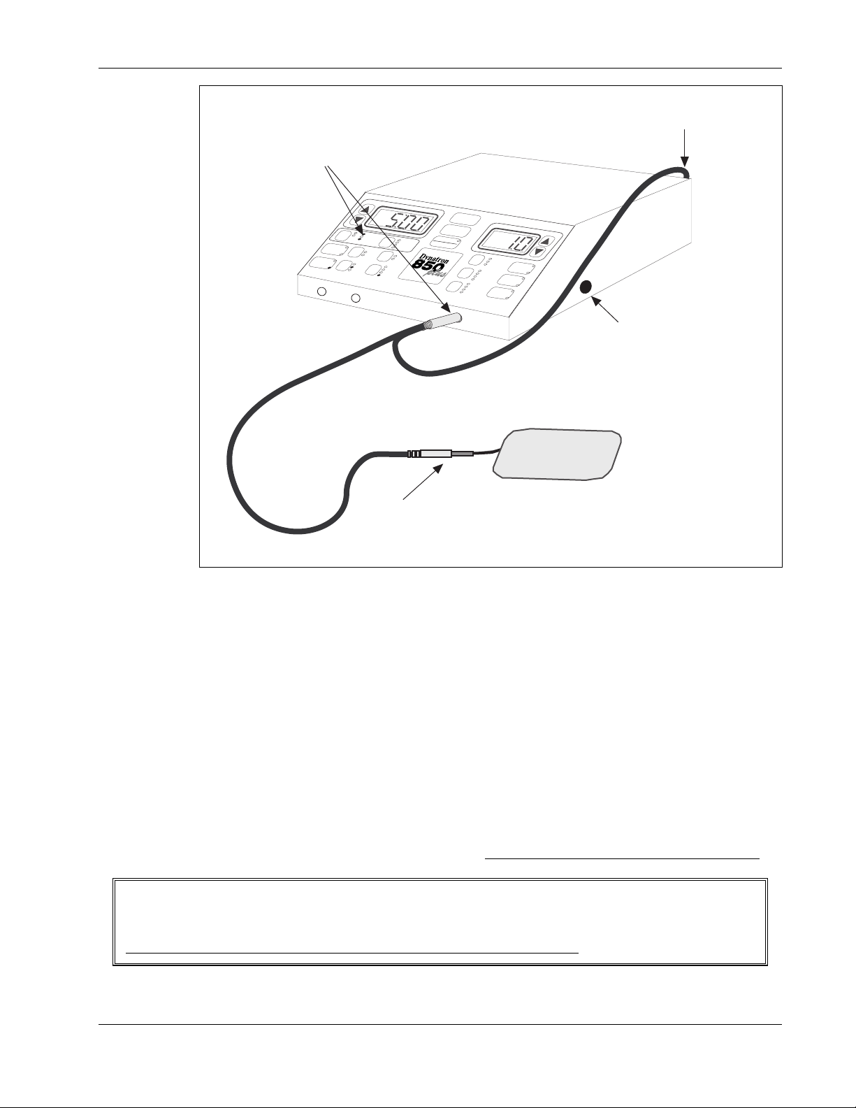
Dynatron® 850plus & 550plus
When you select COMBO and select the
stim modality to be combined with
ultrasound, the device automatically
chooses an ouput jack for the treatment.
Plug the special combo lead wire into
stim jack selected.
Plug the banana end of the combo lead wire into
stim input jack on the back panel of the D850plus
1
HV
2
CH
MICRO
SOUND
IFC
COMBO
SOUND
C
PREMOD
H
1
HIGH
LOW
1 MHz
2 MHz
3 MHz
CH 2
Connect an electrode to the pin end of the special
COMBO lead wire. Attach the electrode to the patient.
Special Combo Lead Wire. Stereo jack attaches to any of the channels. Banana end plugs into the
stim input on the back of the device. The pin end of the lead wire attaches to an electrode.
Stim Through the Soundhead
With combination therapy, the soundhead is used in place of one electrode for a stim
treatment; and electrotherapy current is delivered through the soundhead. This means that for
a normal 2-electrode stim treatment therapy, you would place one electrode on the patient and
use the soundhead as the second electrode site to complete the setup. A patient lead wire
designed to accommodate this setup is included in the Dynatron 850plus standard accessory
package.
During the treatment, the stim current passes between the soundhead and the other electrode.
At the same time ultrasonic waves are introduced into patient tissue through the soundhead.
Avoid touching the electrode with the soundhead during the treatment, keep the soundhead in
contact with the patient’s skin at all time, and keep the intensity low for the stim current
TIME
TIME
FREQ
RATE
WIDTH
TARGET
SWEEP
10%
20%
50%
CONT
TARGET
PAUSE
FUNCTION
STOP
START
POWER-INTENSITY
NORMAL
CO-CONT
RECIP
BIPHASIC
RUSSIAN
10/10
10/30
10/50
+
HI VOLT
CONT
.5 RAMP
1.0 RAMP
1.5 RAMP
2.0 RAMP
H
V
MICRO
-
+
-
The soundhead should be
firmly plugged into this jack
before the device is turned on.
P ALS and P ALS PLUS
.
When setting up a combination treatment, observe all contraindications, warnings, and precautions
for both therapies to be used.
REMEMBER: Use a very low stim intensity for all combo treatments!
Treatment Instructions - COMBINATION
57
Page 66

Dynatron® 850plus & 550plus
Combination Therapy Setup
In order to set up a combo treatment, you must be familiar with setup instructions for both the
electrotherapy modality to be used and ultrasound as explained earlier in this manual. Also
remember:
• When a channel’s LED is green, the treatment parameters for that output are
displayed. Any changes you make to the parameters will affect that channel only.
• When an indicator light is yellow, the channel is active, but its parameters are not
being displayed and may not be modified at this time. You must first press the
channel toggle key (CH) to select the channel—its light will then become green and
modifications are allowed.
Since ultrasound and stim share the Time and Power-Intensity displays during a
combination treatment, you will need to observe the indicator lights when setting up or
changing treatment parameters. You may toggle between the stim and sound channel
using the channel toggle key.
You may set up either the ultrasound or the stim treatment first. The Channel Toggle key
allows you to switch between channels to select the treatment type to be set up first.
When the Sound indicator light is green, you can set up ultrasound parameters. When the
stim channel light is green, you can set up the electrotherapy parameters. The treatment
timer does not begin until you press Start after both modalities have been set up.
1. Press the SOUND/COMBO key twice to select COMBO. If desired, you may now set up
the Sound portion of the treatment. Then toggle to the stim channel by pressing START
or the channel toggle key; or press the appropriate key to select the desired electrotherapy
modality (Premod, Biphasic, Russian, High Volt, or Microcurrent). The front panel of
the device shows the following default selections:
• The COMBO LED is lit.
• The selected modality key is lit.
• The first available channel for the stim therapy chosen is indicated by a GREEN
light. The SOUND channel light is YELLOW.
• The TIME display shows 5 minutes (or other time if you have changed this default).
2. Attach the lead wire to channel jack that corresponds with the channel light for the
modality chosen. Apply the stim electrode to the patient now. Apply conductive gel to
the ultrasound treatment site now.
Set up Biphasic, Russian, Premod, High Volt or Microcurrent:
1. The stim channel light must be green before setting up the stim treatment. Press the
Channel Toggle key, if needed, to select the stim channel. (NOTE: Combination with
microcurrent requires Channel 1 to be used.)
2. If the modality you wish to use is not already selected (Premod, Russian, Biphasic, High
Volt, or Microcurrent) press that modality key now. When a modality key is pressed, the
LED on that key is lighted while the COMBO LED remains lighted as well. Again, make
COMBINATION - Treatment Instructions
58
Page 67

Dynatron® 850plus & 550plus
sure the combo lead is plugged into the correct output jack for the stim modality you
have selected.
3. Enter treatment parameters for the selected modality as instructed earlier in this manual.
4. Place the soundhead at the treatment site making good contact with the skin (be sure you
have applied conductive gel first). Raise the stim intensity to the desired level. If the
soundhead is in proper position and coupling is good, the patient will feel the current. If
the patient does not feel the current, check to be sure coupling is good and make sure you
have used ample conductive gel.
KEEP THE STIM INTENSITY LOW!
Set up Sound:
Continue to keep the soundhead in contact with patient skin during ultrasound setup.
1. The Sound indicator light must be green before setting up ultrasound parameters. Press
the Channel Toggle key, if needed, to select SOUND.
2. Enter ultrasound parameters as described in “Ultrasound Instructions” earlier in this
manual.
After both modalities are set up:
Continue to ensure the soundhead is making contact with the patient’s skin.
1. Press START.
If you fail to set the intensity or ultrasound power before pressing START, the Power-
Intensity display will begin flashing, and you will be unable to start the treatment until
you set the intensity. Remember that you must set both the intensity for the stim
treatment and the power for the sound treatment.
NOTE: SAVE DEFAULTS. The default combination treatment includes ultrasound
with premodulated treatment for five minutes. The stim treatment parameters are derived
from the defaults for that modality You may change the default stim modality for
COMBO treatments to any of the stim modalities available with COMBO. You may also
set a new default treatment time, if desired.
To save new default settings, after setting up the treatment, press and hold the START
key for two seconds. At the end of two seconds, you will hear a beep indicating the
treatment parameters have been saved. If you changed any parameters for the stim
modalities during this treatment setup, those parameters will also be saved as the new
default settings for that modality. Any ultrasound parameters that are saved will apply
only to combo treatments—separate ultrasound treatments may have separate default
settings.
9. Press STOP if it is necessary to stop a treatment before time has expired.
When the treatment time has elapsed, the current to the patient stops and a tone sounds
notifying you of the treatment end. Treatments in progress may be stopped at any time
using one of the following methods.
STOP: Press this key to stop all treatments at all channels.
59
Treatment Instructions - COMBINATION
Page 68

Dynatron® 850plus & 550plus
REMOTE STOP: During “unattended therapy,” a patient stop button is provided to
allow the patient to stop treatment. The remote cord should be plugged into the machine
prior to starting the treatment. When the remote stop button is pressed, all output from
the device is stopped, time is set to zero, and a tone sounds briefly.
STOP ONE TREATMENT ONLY: If you have more than one treatment in progress,
you can stop one treatment by either of the following methods. First, press the channel
toggle key to select the channel to be stopped (that channel’s light is green when
selected).
FUNCTION-STOP. Press and hold the FUNCTION key and press STOP.
REDUCE THE TREATMENT TIME TO ZERO. Press the Time down arrow
until the Time display reaches zero. The device beeps when the time reaches
zero.
The output for the channel(s) selected is stopped (during a combo treatment this includes
both stim and sound channels), and the device then displays the parameters for the next
treatment that remains in progress (if any).
NOTE: Pausing a Combo Treatment
In Combo mode, if a treatment is paused by any means (either by pressing the PAUSE key or as a result of
a soundhead that has become too hot), the ultrasound output is stopped and the treatment timer is paused.
However, the stim current continues to be delivered. Therefore, the pause condition should be corrected as
quickly as possible and the treatment resumed, or the treatment should be stopped completely by pressing
the STOP button.
If the button on the REMOTE STOP cable is pressed during a Combo treatment, both the sound and the
stim portions of the treatment are stopped at once.
Modify Treatment
• Modifications to a treatment in progress may be made to both modalities used. See the
instructions earlier in this manual for specific modification instructions for each modality.
Keep in mind that since the stim and the ultrasound modalities share the Time and
Power-Intensity displays, you will need to select the desired output channel with the
channel toggle key before making changes to the ultrasound or the stim portion of the
treatment.
• Treatment time for both treatments is simultaneous. Changing the treatment time affects
both therapies.
COMBINATION - Treatment Instructions
60
Page 69

Dynatron® 850plus & 550plus
Combination Default Settings
The factory default for a combination treatment is an ultrasound treatment with a
premodulated treatment and the respective default settings for those two modalities.
If you save defaults during a Combo treatment the following settings are saved:
• The stim modality that is selected for the current combo treatment is saved as the default
stim treatment for combo.
• Stim parameters for this setup are saved, and become the default settings for that stim
modality both during combo and during separate treatments.
• Ultrasound parameters for this setup are saved, and become the default ultrasound
settings for combination treatments only (non-combination ultrasound treatments may
have different default settings).
• The treatment time is saved as the default treatment time for combination treatments.
61
Treatment Instructions - COMBINATION
Page 70

Dynatron® 850plus & 550plus
Simultaneous Treatments
The Dynatron 850plus and 550plus allow several combinations of simultaneous treatments to
be delivered at once using available channels. Simultaneous treatments are not the same as
combo treatments. A combo treatment combines ultrasound with a stim therapy into a single
treatment. A combo treatment is always delivered to one patient. Simultaneous treatments
are independent treatments that are set up separately, that have separate treatment timers, and
which may be delivered to one or more patients at the same time.
You can set up any number of separate treatments as described below with the exceptions
noted:
• Channels 1 and 2 may be used for one interferential, two premodulated, one
premodulated and one Russian, or one premodulated and one biphasic treatment. For
treatments using one channel, the device will select the next available channel. For
treatments using two channels, the device will select both channels 1 and 2.
• Russian or biphasic parameters selected will apply to both channels in a channels 1 and
2 at once. Therefore, you cannot have both a Russian and a biphasic treatment
simultaneously. You may deliver two biphasic or two Russian treatments.
• A separate High Volt treatments may be set up regardless of any other treatments that
may be currently running.
• A separate Ultrasound treatment may be set up, or a combination treatment using
ultrasound and a single-channel modality with any available channel.
• The device allows only ONE attended therapy
therapies include ultrasound, microcurrent probe, and high volt probe treatments. While
the attended therapy is in progress, other available channels may be used for unattended
treatments (subject to availability of the channel needed).
• Microcurrent therapy is delivered only through Channel 1 and
Microcurrent Probes output jack at the same time. Whenever any microcurrent
treatment is in progress (probes or electrodes), Channel 1 is unavailable for any other use.
However, Channel 2 may be used for other stim treatments.
Set Up A Second Treatment
To set up the second (or third) treatment, after you have set up and started the first modality,
press the modality key for the second treatment to be set up. The device automatically selects
the treatment channel(s) to be used. The green channel light shows you the channel(s)
selected for this treatment. Plug the lead or cable into the corresponding output jack(s) before
you proceed with setting up the treatment.
Select the treatment parameters for the second treatment following the setup instructions for
that modality provided in this manual. When parameters have been entered, press START.
to be delivered at one time. Attended
through the
Simultaneous Treatments
62
Page 71

Dynatron® 850plus & 550plus
Modify Simultaneous Treatments
You may VIEW and MODIFY parameters for the channel with the GREEN light.
While two or more treatments may be in progress at once, the “Time” display and the
“Power-Intensity” displays can show the settings for only one channel at a time. The settings
displayed are for the channel with the GREEN light only. Any other channel in use at that
time will have a YELLOW light to show it is active (delivering current) but its parameters are
not currently displayed.
To change the settings for a channel or output that has a YELLOW light, press the channel
toggle key one or more times until the light for the desired channel becomes GREEN
hear a beep each time you press the channel toggle key. The Time and Power-Intensity
displays also change to show the parameters currently in effect for the channel indicated by
the green light.
CHANNEL / OUTPUT INDICATOR LIGHTS
GREEN Solid • You CAN see and modify this channel’s parameters.
• The channel is delivering current.
GREEN Flashing • You CAN see and modify this channel’s parameters.
• The channel is not delivering current while the light is flashing.
YELLOW Solid • You CANNOT see or modify this channel’s parameters at this time.
• The channel is delivering current.
YELLOW Flashing • You CANNOT see or modify this channel’s parameters at this time.
• The channel is not delivering current while the light is flashing.
. You
Stop One Treatment
STOP ONE TREATMENT ONLY: If you have more than one treatment in progress, you
can stop one treatment by either of the following methods. First, press the channel toggle key
to select the channel to be stopped (that channel’s light is green when selected).
FUNCTION-STOP. Press and hold the FUNCTION key and press STOP.
REDUCE THE TREATMENT TIME TO ZERO. Press the Time down arrow until the
Time display reaches zero. The device beeps when the time reaches zero.
The output at the selected channel is stopped, and the device then displays the parameters for
the next treatment that remains in progress (if any). Pressing the STOP key or the Patient
Remote Stop button will stop all treatments at once.
REMOTE STOP: During “unattended therapy,” a patient stop button is provided to allow the
patient to stop treatment. The remote cord should be plugged into the machine prior to
starting the treatment. When the remote stop button is pressed, all output from the device is
stopped, time is set to zero, and a tone sounds briefly.
63
Simultaneous Treatments
Page 72

Each of the modalities has default settings that are automatically selected when you press that
modality key. The default setting feature allows you to set up a treatment with common
treatment parameters in just seconds. For guidance in selecting the appropriate settings for
each modality, consult published medical literature.
Save New Defaults
If your most common treatment settings are different than the ones already set for this device,
you can change the defaults to suit your own preferences. Setting new defaults is simple.
And defaults may be changed again and again whenever needed.
1. Press the modality key desired (IFC, Premod, Russian, Biphasic, High Volt, Micro, or
Sound).
2. Set up a treatment using your preferred settings.
3. If this is an actual treatment you may increase the intensity now (intensity is not saved
with the default settings). This step is optional.
4. PRESS and HOLD the START key for two full seconds to SAVE the new settings.
You will hear a beep to signal that the new settings have been saved.
If the intensity was set before you pressed the START key, the treatment will begin upon
pressing START. You may proceed with delivering the treatment now, or you may stop the
treatment.
Example:
If, for example, your most common premodulated treatment uses the alternating High/Low
frequency setting and you prefer to treat for 15 minutes. Set the new defaults as follows:
1. Press PREMOD.
2. Press the HIGH/LOW toggle key one or more times until both the High and the Low
indicator lights are on.
3. Use the TIME arrow keys to change the time to 15 minutes.
5. PRESS and HOLD the START key for two full seconds.
Dynatron® 850plus & 550plus
Setting Defaults
NOTE: You can save defaults at any time during treatment setup or while a treatment is in
progress. Select the desired channel, then press and hold the START key for two seconds. A beep
confirms that the new settings have been saved. Only defaults for the selected channel are saved.
Setting Defaults
64
Page 73

Dynatron® 850plus & 550plus
Restore Factory Defaults
If you have saved your own defaults, but would like to return ALL your default settings to
those that were set at the factory, do the following:
1. Turn the machine off.
2. Press and hold the START key while turning the machine on. Continue holding the Start
key down until you hear machine beep briefly and you see the display message “RST FP”
which indicates the parameters have been reset. You may now proceed with treatment
setup.
Interferential Default Settings
• High
• Target
• Channels 1 and 2
• Time: 10 minutes
• Frequency Ranges (for both Interferential and Premodulated)
Default High Range: 80-150 Hz
Default Low Range: 0-10 Hz
Available Range: 0-150 Hz
Premodulated Default Settings
• High
• The first available channel (1 or 2)
• Time: 10 minutes
• Frequency Ranges (for both Interferential and Premodulated)
Default High Range: 80-150 Hz
Default Low Range: 0-10 Hz
Available Range: 0-150 Hz
NOTE: The default frequency ranges and the High/Low option you set will be the default
settings for both Interferential and Premodulated treatments. However, every treatment may
be modified to have unique settings regardless of the defaults you set.
Russian / Biphasic Default Settings
• Normal mode
• 10/30 contraction/rest times
• Treatment time: 10 minutes
• Ramp up and down time: .5 sec.
Russian Stimulation:
Default Setting Valid Range
Pulse Rate 50 Pulses per second 1 to 500 (depends on Pulse Width)
Pulse Width 10 mSec .4 to 50 mSec
Biphasic Stimulation:
Default Setting Valid Range
Pulse Rate 50 Pulses per second 1 to 500
Pulse Width 200 µSec 50 to 400 µSec
65
Setting Defaults
Page 74

Dynatron® 850plus & 550plus
High Volt Default Settings
• Continuous on time
• Treatment time: 10 minutes
• Ramp up and down time: .5 sec.
• Polarity: Negative
• Pulse Rate
Default High Range: 80-120 Hz
Default Low Range: 1-10 Hz
Available Range: 1-200 Hz
Microcurrent Default Settings
The Microcurrent treatment setup with electrodes is the default, and the following defaults are
selected:
• Bipolar wave
• .3 Hz frequency
• 50 µA intensity
• Time: 20 minutes, counts down
• Audible Tone: Off
If Probe treatment is selected, the following defaults are automatically selected:
• Negative unipolar wave
• 4 Hz frequency
• 300 µA intensity
• Time: zero, counts up
• Audible Tone: On
Available Ranges for both Electrodes and Probes:
• Frequency: Between .1 and 500 Hz
• Intensity: Between 10 and 990 microamps (in increments of 10µA).
NOTE: For Microcurrent treatments you may save separate default settings for a probe
treatment and for a treatment with electrodes. You may also indicate the most preferred
option (between probes and electrodes). The last default setting saved (probes or electrodes)
becomes the primary default when Microcurrent is selected.
Ultrasound Default Settings
• 1 MHz for 2, 5, and 10cm
• Continuous
• Time: 5 minutes
Combination Default Settings
In Combo mode you can save new default treatment time and the preferred stim modality.
The stim settings in a Combo treatment are determined by the defaults of the that modality.
Separate ultrasound default settings may be saved for the combo treatment which will not
affect ultrasound-only treatments.
2
soundheads, and 2 MHz for the 1cm2 soundhead
Setting Defaults
66
Page 75

Dynatron® 850plus & 550plus
Battery Operation
Use ONLY a Dynatronics-Approved Battery
Contact Dynatronics or your Dynatronics dealer to purchase the optional battery or to obtain
specifications for an acceptable battery that may be used.* Do not substitute another battery without first
confirming with Dynatronics that the battery you are purchasing may be used with this device.
Only use a battery that CANNOT be recharged while it is in use. Disconnect the battery charger
from the AC power source before using the battery to supply power to this device.
An optional battery is available for the Dynatron 850plus and 550plus, allowing you to
deliver up to hours of battery-powered treatments wherever power may be unavailable or
unreliable. To use the optional battery, do the following:
1. Before use, ensure the battery has been adequately charged. DISCONNECT
charging cable from the battery while it is in use for treatment.
2. Plug the battery adapter into the jack labeled BATT on the back of the Dynatron 850plus
or the 550plus device. Turn the battery pack on.
4. Set up and deliver treatments as you normally do.
5. When available battery power is reduced to a certain level, the device will flash a
message BATT LO to indicate low battery power. The treatment can continue but you
will probably be unable to set up and deliver another treatment when the current
treatment has ended.
6. When the available battery power becomes too low to continue operating the device, the
BATT LO message is again displayed, the treatment intensity is ramped down, and the
machine is then shut off. Before you can continue with battery operation of the device,
you must recharge the battery. If battery power is fully depleted, the message BATT
BAD is displayed to indicate either a bad battery or to indicate the battery must be
recharged. Any treatments that were running at that time will stop.
NOTE: Use the ON/OFF switch on the battery pack
to control power to the device during
battery operation. While the battery is attached to the Dynatron 850plus or 550plus device,
the battery’s ON/OFF switch controls power to the device, overriding the device’s own
ON/OFF switch.
the battery
67
General Modality Information
Page 76

Battery Requirements
• 12 volt and at least 5 amps peak current (1.5 ampere hours minimum).
• Battery adapter cord
- Cigarette lighter plug on one end (to attach to the battery pack) and a barrel plug on
the other end (to fit a .325 barrel jack).
- The cord needs to be a high quality gauge wire. Radio Shack carries a high quality
cord that is recommended. Cat. No. 270-1534D. This cord comes with a 2 amp fuse.
This needs to be replaced with a 5 amp fast blow fuse.
Note: If a low-quality gauge cord is used, you can get the BATT LO error when the
battery is not low.
Battery Life
The length of time that a unit can be used with a battery pack is dependent on several factors:
• The amperage of the battery pack. A larger amperage will provide longer use.
• The modality used. Ultrasound requires more power than stim modalities.
• The intensity of the treatments. The higher the intensity, the higher the consumption of
power.
• The use of multiple treatments. The more channels used, the more power is consumed.
• The amount of charge remaining on the battery.
As a general rule, the unit may be run continuously for 30 minutes to several hours depending
on these factors.
Dynatron® 850plus & 550plus
General Modality Information
68
Page 77

Dynatron® 850plus & 550plus
Section III
General Modality Information
69
General Modality Information
Page 78

Dynatron® 850plus & 550plus
Interferential and Premodulated Therapy
Interferential (Quadpolar) Therapy
Interferential therapy uses four electrodes to
deliver two currents, one current with a
constant frequency of 4000 Hz and the other
current with a variable frequency of 4,001 to
4150 Hz. The paths of these two currents
cross resulting in a “beat” that produces the
therapeutic frequency at the treatment site.
The resulting frequency is between 1 and 150
Hz. An example of wave forms representing
these currents is illustrated here.
CHANNEL 1
4000 Hz
CHANNEL 2
4001 - 4150 Hz
In the interferential
mode, two output jacks
(Channels 1 and 2) are
utilized with four
electrodes placed in a
Direction of
Area of low
stimulation
intensity
Skin Surface
Electrode
Stimulation produced by 4 electrodes.
stimulation
High stimulation
intensity
where currents
cross
criss-cross fashion, “bracketing” the treatment site as shown in the
illustration to the left. The output from Channel 1 is the constant
4000 Hz wave, while the output of Channel 2 is the variable 4000 to
4150 sine wave.
Premodulated (Bipolar) Therapy
Premodulated therapy utilizes one output jack and two electrodes. The current delivered is a
composite wave form. In order to produce this composite current, two frequencies are
“mixed” within the device prior to output. One frequency is 4000 Hz while the second
frequency covers a range between 4000 to 4150 Hz.
With the Dynatron 850plus and 550plus, either of the two channels may be used
simultaneously to deliver two separate, independent premodulated treatments. A criss-cross
electrode setup pattern should not
Note that a premodulated treatment usually requires a lower intensity setting than an
interferential treatment since current is dispersed to only two electrodes rather than four (a
smaller total dispersement area means greater current density at the treatment site).
The “beat” phenomenon. Two waves of
different frequencies over 4000 Hz, combine to
produce a beat which is between 1 and 150 Hz.
be used when setting up multiple premodulated treatments.
IFC & PREMOD - General Information
70
Page 79

Target
The Dynatron 850plus and 550plus feature Dynatronics’ patented TARGET feature (available
for interferential treatments only) simplifies electrode placement for an interferential treatment.
Interferential treatment is performed using four electrodes with two channels. The channels
produce two currents which intersect producing the interferential “beat.” Without Target, it is
often difficult to place the electrodes in the right position to produce the beat at the desired
treatment area. This is because different types of human tissue (skin, muscle, bone, etc.)
conduct current differently, making it impossible to guess the course of the two currents.
Target helps eliminate the need to move the electrodes to get the desired result.
With Dynatronics’
patented Target feature,
you can move the center
of interference (where
the two currents cross)
simply by moving your
finger across the Target
touch pad. Patient
feedback will let you
know when you have
positioned the treatment
at the desired spot.
In the diagram here the
electrodes are placed in a position to treat a point directly in the center of the electrodes. But
the center of interference actually occurs at another point. (In these illustrations the point of
interference is shown in a cloverleaf shape as interferential treatment affects a cloverleafshaped area.) Using the Target pad, the point of interference in easily moved to the desired
treatment area.
Why Is Target Better?
Channel
1
A
Channel
2
Other devices increase current at one
channel while decreasing it at the other.
This merely rotates the treatment. The
center of interference does not move.
Channel
2
Channel
1
Dynatron® 850plus & 550plus
Channel
2
Channel
Channel
1
Channel
1
2
Channel
2
Channel
1
Channel
1
Channel
2
Normal Interferential currents cross at a point between electrodes. It is
difficult to guess where they will cross as shown in the left diagram. With
Target, you move the point of interference without moving electrodes (as
shown in the diagram on the right)—just press the touch pad.
The Dynatron 850plus and 550plus employ a unique, patented
method which actually moves the center of interference. With
Target, the voltage output from both channels remains equal at all
times; so wherever the treatment is applied, a full, deep interferential
beat occurs. Other devices attempt to achieve this effect by
increasing the current from one channel while decreasing the current
from the other channel. This method only rotates the cloverleafshaped area, but the center of interference does not move. In
addition, the depth of the beat is reduced.
71
General Information - IFC & PREMOD
Page 80
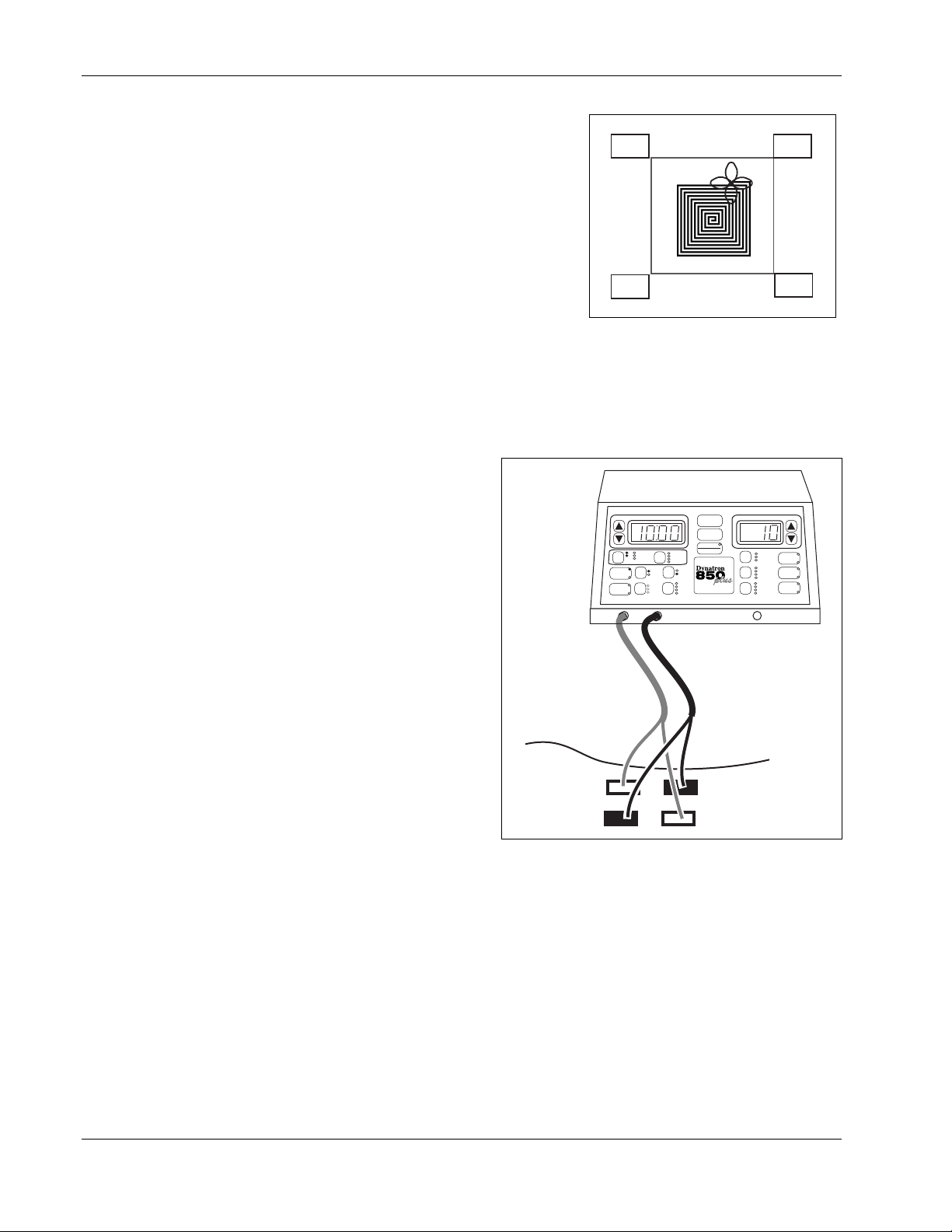
Dynatron® 850plus & 550plus
Sweep
You can use the Sweep (Target Sweep) feature to
bathe a wider area with the interferential current—
up to 80 percent of the area within the electrodes
may be covered. The Sweep feature utilizes the
patented Target feature and moves the point of
interference to cover a wider treatment area while
still retaining the full interferential beat.
The Sweep option literally moves the point of
interference inward and outward in a somewhat
spiral pattern as shown in the illustration to the right,
bathing about 80 percent of the area within the
electrodes with the interferential current.
Interferential Electrode Placement
When performing interferential therapy
with a two-channel/four-electrode
setup, it is important to arrange the
electrodes in a criss-cross manner so the
current from one channel will intersect
with the current from the second
channel at the point where treatment is
to be delivered.
Consult published literature for
electrode placements for specific sites
and conditions.
Channel
1
Channel
2
Sweep bathes a larger area with the
interferential current.
1
2
IFC
PREMOD
SOUND
COMBO
CH 1 CH 2
TIME
HV
MICRO
SOUND
HIGH
LOW
1 MHz
2 MHz
3 MHz
START
STOP
PAUSE
FUNCTION
TIME
FREQ
RATE
WIDTH
TARGET
SWEEP
10%
20%
50%
TARGET
CONT
POWER-INTENSITY
NORMAL
CO-CONT
RECIP
10/10
10/30
10/50
CONT
.5 RAMP
1.0 RAMP
1.5 RAMP
2.0 RAMP
HV
Channel
2
Channel
BIPHASIC
RUSSIAN
HI VOLT
MICRO
1
+
-
+
-
IFC & PREMOD - General Information
72
Interferential Electrode Placement
Page 81

Dynatron® 850plus & 550plus
Russian / Biphasic Therapy
Russian Stimulation
With the Dynatron 850plus and 550plus’ Russian stimulation mode, the output of the device
is a 2500 Hz sinusoidal wave. Russian stimulation currents produce strong muscle
contractions.
The Dynatron 850plus and 550plus allow you complete control over all the parameters of the
Russian Stimulation treatment. Three treatment modes include Normal for firing one muscle,
Reciprocal for firing two different muscles at different times, and Co-contraction for firing
two different muscles simultaneously. The Dynatron 850plus and 550plus allow you to
choose a muscle contraction/relaxation cycle from options of 10/10 (ten seconds on and ten
seconds off), 10/30, 10/50, or continuous cycle. (The continuous duty cycle is not
recommended for electrical muscle stimulation, but may be used for settings that are intended
to effect other results than a muscle contraction.) In addition, you can modify the pulse rate,
the pulse width, and the ramp time.
The Normal mode requires use of just one output jack (Channel 1 or 2). The Reciprocal and
Co-Contraction modes utilize both channels 1 and 2.
Biphasic Stimulation
The biphasic stimulation feature is similar to Russian stimulation in the parameters that are
selected and in the available options. It differs from Russian stimulation in the pulse width
and rate ranges. Additionally, the biphasic pulse includes just one cycle (including one
positive phase and one negative phase) per pulse.
Biphasic / Russian Parameters
The Dynatron 850plus and 550plus offer even greater control over the Russian and biphasic
stimulation treatments through customization of the pulse rate and the pulse width. The
default settings and the available ranges for each of these are as follows:
Biphasic Stimulation:
Default Setting Valid Range
Pulse Rate 50 Pulses per second 1 to 500
Pulse Width 200 µSec 50 to 400 µSec
Russian Stimulation:
Default Setting Valid Range
Pulse Rate 50 Pulses per second 1 to 500
Pulse Width 10 mSec .4 to 50 mSec (depends on Pulse Rate)
The pulse rate and width should not be confused with the contraction/rest times in the
treatment as these are different parameters; the pulse occurs only during the contraction time.
The diagrams below illustrate the relationship of each of these parameters.
73
General Information - BIPHASIC & RUSSIAN
Page 82
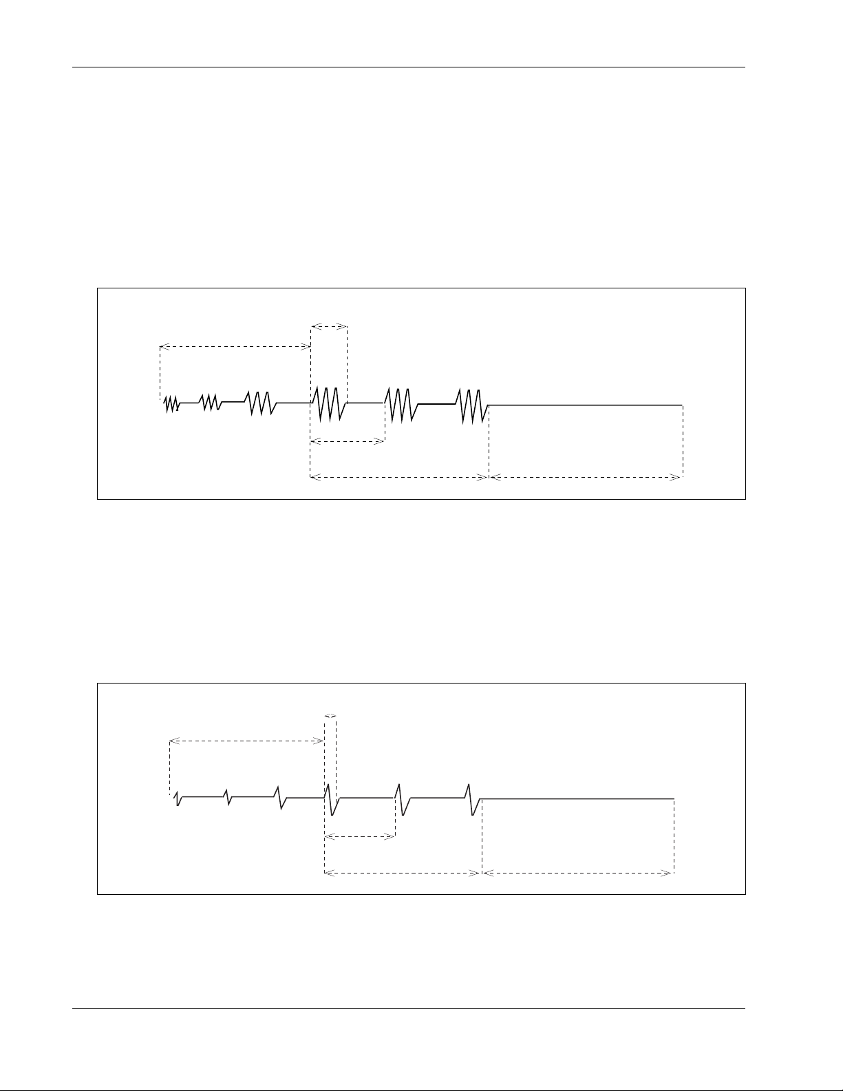
Dynatron® 850plus & 550plus
The pulse width indicates the duration (in milliseconds or microseconds) of the output cycle
of the pulse, and the pulse rate is measured in number of pulse occurrences per second.
Between pulses, current is at zero.
A 50 percent duty cycle or less is the usual duty cycle for Russian stimulation (the duty cycle
includes one output cycle period and one zero-current period). A 50 percent duty cycle
means that the length of the pulse width must be equal to or less than the zero-current period.
The number of pulses per second affects the allowable range of pulse widths. A greater
number of pulses per second means a shorter pulse width is allowed. The Dynatron 850plus
and 550plus will not allow you to circumvent this rule.
Width
Ramp
Rate
Russian Stimulation.
If a given Russian stimulation treatment has a 50 percent duty cycle, this means the output
cycle is continuously repeating for half of the pulse duration (see “Rate” in the diagram
above) followed by a zero-current period for the other half of the pulse duration.
Biphasic stimulation differs from Russian stimulation in the pulse width and rate ranges, as
explained above. In addition, the biphasic pulse includes just ONE output cycle per pulse.
As shown in the diagram below, one pulse cycle (including one positive phase and one
negative phase) occurs, followed by a zero-current period .
Biphasic Stimulation.
Ramp
Contraction
Width (Duration)
Rate
Contraction
Rest
Rest
BIPHASIC & RUSSIAN - General Information
74
Page 83

Dynatron® 850plus & 550plus
The pulse rate and width may be modified during setup of a Russian or Biphasic Stimulation
treatment or may be modified while a treatment is in progress.
Since a channel pair shares pulse parameters during a Russian or biphasic treatment, you
cannot deliver both a Russian and a biphasic treatments at the same time with this device.
You can deliver two Russian or two biphasic treatments at once.
NOTE: If a biphasic or Russian stimulation treatment is in progress on one channel,
you may not customize the pulse rate and width for the second channel. When you
customize the pulse rate and width, it affects all simultaneous biphasic or Russian stimulation
treatments for both channels (1 and 2).
If you are modifying the pulse rate and width for a treatment in progress, you should also
modify the intensity, as all three of these parameters will affect delivered energy and patient
comfort.
75
General Information - BIPHASIC & RUSSIAN
Page 84

Dynatron® 850plus & 550plus
High Volt Therapy
High voltage pulsed stimulation is a pulsed DC current with pulse widths in the microsecond
range and pulse rates ranging from 1 to 200 Hz, with a peak amplitude of up to 1.0 A
utilizing a twin-peak monophasic waveform.
The Dynatron 850plus and Dynatron 550plus provide the option of one high volt treatment
using the dedicated channel labeled HV. The treatment utilizes one channel with one or more
active electrodes and a large dispersive electrode. Electrodes are placed on opposite sides of
the affected area so treatment is “through” the affected area. An optional probe is available to
accommodate hands-on treatment delivery.
High Volt Therapy with Electrodes
High volt therapy may be delivered as an unattended treatment using electrodes. This
treatment setup uses one channel with two or more electrodes for unattended treatment. One
electrode acts as the dispersive electrode, and one electrode is the active electrode. The
active electrode is placed over the treatment site. It is recommended that the dispersive
electrode be at least double the size in area of the active electrode. The lead for the active
electrode may be bifurcated allowing placement of two active electrodes. However, the area
of the dispersive electrode is recommended to be at least double the combined total area of
the active electrodes.
High Volt with Optional Probes
High volt therapy with probes accommodates hands-on treatment. This therapy utilizes a
high volt probe and a dispersive electrode. The high volt probe is an optional accessory and
is not included in the standard accessory package for the Dynatron 850plus and 550plus.
High Volt Waveform
The high volt waveform is a twin-peak monophasic
decaying waveform with either positive or negative
polarity.
High Volt Settings
High and Low Sweep Pulse Rate. The user may
select High (80-120 Hz) or Low (1-10 Hz) frequency
ranges. During a treatment, the device scans through
the range of frequencies selected. The settings for
these pulse rate ranges may be modified and saved
by the user. The available range is 1 to 200 Hz.
Single Pulse Rate. The pulse rate may be set to a
Limited to less than 500 V, open load
100µs pulse
interval spacing
High Volt Waveform for positive
polarity
At one-half
amplitude, pulse
width is 25µs
HIGH VOLT - General Information
76
Page 85

Dynatron® 850plus & 550plus
single pulse rate instead of a range. The pulse rate is selected from a range of 1 to 200 Hz.
Selectable Polarity. Positive or Negative monophasic current may be selected. You may
also select both positive and negative and the current delivered alternates between the two
polarities.
Selectable Duty Cycle. Continuous or on/off duty cycles may be selected. The Dynatron
850plus and 550plus allow you to choose a muscle contraction/relaxation cycle from options
of 10/10 (ten seconds on and ten seconds off), 10/30, 10/50, or continuous cycle.
Selectable Ramp Speed. You can choose a ramp speed of 1/2 to 2-1/2 seconds in halfsecond increments. For patient comfort, the ramp occurs both before and after the “On”
segment of the pulse.
Pulse Width. The pulse width is fixed at 25 µs.
Pulse Pair Interval. The interval between the two pulses in the wave form is fixed at 100 µs.
Intensity Display in Volts. The intensity display is shown in volts (peak voltage with no
load) with a range of 1 to 500.
77
General Information - HIGH VOLT
Page 86

Dynatron® 850plus & 550plus
Microcurrent Therapy
Microcurrent is low-volt pulsed microamp stimulation which has been used for symptomatic
relief of chronic intractable and post-surgical pain.
With the Dynatron 850plus or 550plus you can provide attended or unattended microcurrent
therapy. Unattended therapy is delivered using electrodes. Attended therapy is delivered
using an optional hand-held probe.
Microcurrent Therapy with Electrodes
Microcurrent treatment setup with electrodes is provided using Channel 1 and two electrodes.
Electrodes are placed on opposite sides of the affected area so current is directed “through”
the affected area.
Microcurrent Therapy with Probes
Microcurrent therapy with probes accommodates hands-on treatment for a variety of
applications. With the Dynatron 850plus and 550plus, you can use the optional treatment
probes to measure tissue conductance both before as well as during the treatment. The probes
are used to treat very small areas, or to easily deliver treatment to a number of different areas
in succession. This therapy utilizes the active probe and the ground probe. If desired, a
dispersive electrode may be substituted for the ground probe. The active and ground probe
are optional accessories for this device.
Microcurrent Waveforms
Three different output
waveforms (polarity) may be
selected with the Dynatron
850plus and 550plus: The first
two are unipolar square waves
having a monophasic pulse at a
50 percent duty cycle (equal on
and off times). In the
illustration above, the first
unipolar waveform has negative polarity only, and the second has positive polarity only. The
third waveform is a bipolar (negative and positive) square wave with a 50 percent duty cycle.
Microcurrent Settings
The Dynatron 850plus and 550plus offer the following ranges of microcurrent settings:
• Pulse Frequency Range: .1 to 500 Hz
• Microcurrent Pulse Output Current Range: 10 to 990 microamps
Microcurrent Waveform
Negative Unipolar Square Wave
Positive Unipolar Square Wave
For a bipolar square wave, press the toggle key until
both negative and positive waveforms are selected.
MICROCURRENT - General Information
78
Page 87

(For Dynatron 850plus users only. The Dynatron 550plus does not offer the ultrasound
feature.)
About Ultrasound
Ultrasound therapy channels sound waves through muscle, nerve, bone, and connective tissue
to aid in reducing pain, muscle spasms, and joint contractures.
The physiological effect of ultrasound therapy depends upon the frequency of the ultrasound
signal. The lower frequency (1 MHz) penetrates deeper than a higher frequency (such as
2 MHz or 3 MHz), thus the practitioner can decide which frequency to use according to the
condition and depth to be treated.
A section in this manual entitled “Ultrasound Usage Cautions” provides some general
guidelines for ultrasound treatment to help ensure you deliver safe and effective treatments to
your patients. Further information about ultrasound application may be obtained from
published medical literature.
With the Dynatron 850plus, four different soundhead sizes are available—1 cm
2
5 cm
, and 10 cm2 . And, you can select three different frequencies without changing the
soundhead. The 2 cm
2
soundhead operates at 2 and 3 MHz. The desired frequency is easily selected both
1 cm
before and during treatment setup.
SmartHeads
The Dynatron 850plus includes Dynatronics’ new SmartHead™ ultrasound applicator. These
soundheads have calibration numbers programmed into them allowing the soundheads to be
freely exchanged with other Dynatron 850plus units or with the Dynatron 950plus, the
Dynatron 150plus, and the Dynatron 125 models. There is no need to enter calibration
numbers into the device when a new SmartHead soundhead is added.
Patient Coupling
Coupling (acoustic contact between the soundhead and the treatment site) may be provided
either via a coupling agent (such as a gel or lotion) or in water (as with underwater
treatments). Any material used as a coupling agent must be highly conductive of ultrasonic
waves. Air is a very poor conductor of ultrasonic waves. Therefore, avoid allowing any air
between the soundhead and the treatment area. During an ultrasound treatment the device
measures coupling; a flashing TIME display indicates that coupling is poor and should be
corrected. However, a treatment is not automatically paused due to poor coupling unless the
soundhead temperature also becomes too high.
Dynatron® 850plus & 550plus
Ultrasound Therapy
2
, 5 cm2, and 10 cm2 soundheads each operate at 1, 2, and 3 MHz. The
2
, 2 cm2,
79
ULTRASOUND - General Information
Page 88

Soundhead Temperature
When coupling is poor, the temperature of the soundhead rises and the patient does not
receive the full ultrasonic output. The Dynatron 850plus continuously measures the
temperature of the soundhead to ensure both that the patient is receiving the optimal
treatment and that the soundhead crystal is protected from overheating.
If the soundhead temperature approaches the maximum level, the POWER display will begin
flashing. Treatment can continue beyond this warning level, but the user should ensure
coupling is corrected. Under normal circumstances, improved coupling will reduce the
soundhead temperature and allow the treatment to continue.
If the temperature reaches the maximum level, the treatment is automatically paused, the
output power is stopped, a tone sounds and both the TIME and the POWER displays flash.
The soundhead must then be cooled down before the treatment can resume.
The soundhead will cool slowly if placed in the soundhead holder or if held exposed to the
air. Larger soundheads take longer to cool than smaller heads. To resume the treatment right
away, you can place the soundhead in cool/room temperature water to cool the head more
quickly.
NEVER USE ICE OR ICE PACKS TO COOL THE SOUNDHEADS as this is likely to cause
thermal shock to the electronic components of the soundhead and may necessitate a costly
repair. Heads damaged by thermal shock are not covered by the warranty.
When the temperature is again satisfactory, press the START key to resume the treatment;
output power resumes, the displays return to constant, and the timer resumes. As long as the
soundhead is too hot, the device will not allow you to resume the treatment.
To prevent soundhead overheating, check to be sure proper contact is being made throughout
the treatment, or, when treating in water, make sure that the applicator head is completely
under water. For direct coupling, you may need to apply more conductive gel or lotion
during the treatment to achieve better coupling.
You can also reduce the power during the treatment if you are treating an area where it is
difficult to obtain good coupling.
Dynatron® 850plus & 550plus
• Do not drop the soundhead on hard surfaces, do not cool the soundhead with ice water or
ice packs, do not allow the soundhead to reach maximum temperatures repeatedly, and do
not hold the soundhead in the air while it is delivering ultrasonic waves. All of these
conditions are likely to damage the soundhead crystal and/or cause stress to electronic
parts. Damage resulting from these conditions is not covered under the warranty.
ULTRASOUND - General Information
80
Page 89

Dynatron® 850plus & 550plus
Section IV
Contraindications, Warnings, and
Precautions
81
Ultrasound Technical Information
Page 90

Dynatron® 850plus & 550plus
Contraindications, Warnings, & Precautions
for Interferential, Premodulated, Russian,
Biphasic, and High Voltage Pulsed Stimulation
Contraindications
Warnings
Thrombosis: It is possible that the current produces chemical changes in the blood leading
to alterations in the clotting time. At present there is no hard evidence to support this.
Nevertheless, treatment must not be given to any patient who is taking anticoagulants as it
may render these ineffective. The effect of the current is on the platelets and would tend to
spread any clot with perhaps fatal results in a patient with coronary thrombosis. If a patient
has a history of deep vein thrombosis, even many years past, the treatment may increase
rather than decrease swelling.
Pacemakers: Patients with pacemakers should avoid all high and medium frequency
generators.
Cardiac Conditions: The electrodes should be placed to avoid the stellate ganglion and the
heart itself. If there is a potential for heart problems, the clinician must exercise professional
judgment and use adequate precautions. The clinician should not expose the patient to risk if
possible heart problems are suspected.
Bacterial Infections: The effect on bacteria is uncertain, and it is advisable that bacterial
infections should not be treated.
Malignancy: The use of Interferential, Premodulated, High Volt, Biphasic, or Russian Stim
treatment is contraindicated in patients with clinically diagnosed cancer.
Additional warning from the Canadian Health and Welfare Department, Health Protection
Branch: WARNING: Thoracic applications are contraindicated. Cardiac fibrillation may
occur if output current is 50 mA RMS or greater for any output circuit.
1. Adequate precautions should be taken in the case of persons with suspected or diagnosed
epilepsy.
2. Severe spasm of the laryngeal and pharyngeal muscles may occur when the electrodes are
positioned over the neck or mouth. The contractions may be strong enough to close the
airway or cause difficulty in breathing.
3. Caution should be used in the transthoracic application of EMS devices in that the
introduction of electrical current into the heart may cause arrhythmia.
4. This device should be kept out of the reach of children.
5. The Dynatron device should not be used in the following conditions:
• Pregnancy
• Acute and sub-acute thrombophlebitis
• Potentially malignant lesions
Ultrasound Technical Information
82
Page 91

6. The long-term effects of chronic electrical stimulation are unknown.
7. This device should not be used to relieve pain syndromes until etiology has been
Precautions
1. Precautions should be observed following recent surgical procedures when muscle
2. Some patients may experience skin irritation or hypersensitivity due to the electrical
3. Interferential, premodulated, biphasic, Russian and high volt therapy must be used
• When there is a tendency to hemorrhage following acute trauma or fracture.
• Over the menstruating uterus.
4. Use extreme caution when administering a treatment where sensory nerve damage
When treating any conditions contributing to loss of sensation, or any time the patient
Never use high volt therapy to treat an area where there is a loss of normal skin
5. Do not use in general area where high-powered, high-frequency transmitting surgical
6. Do not use the same power outlet or line with a whirlpool and certain traction machines.
7. To avoid causing possible interference with the operation of the Dynatron device, it
Dynatron® 850plus & 550plus
• Implants of any electrical nature
• Do not use over a carotid sinus
• Transcerebrally
• Disturbances in cardiac rhythm
established.
contractions may disrupt the healing process.
stimulation or electrical conductive medium. The irritation can usually be reduced by use
of an alternate conductive medium, or alternate electrode placement.
cautiously in the presence of any of the following conditions:
is present or in any case where there is a loss of normal skin sensation; this includes
areas desensitized by medication. When treating an area where there is loss of feeling,
there is an increased danger of injuring the patient. Do not treat such areas unless you
have sufficient training and experience in applying this therapy for such cases and you
are confident you can deliver the treatment safely without injuring the patient.
cannot feel the electrical stimulation, do not exceed an intensity setting of 12-15 when
using large electrodes (3-3/4” x 1-3/4”) or an intensity setting of 8-10 when using small
electrodes (1-3/4” x 1-3/4”), and select short treatment times (approximately 8 minutes).
Be alert for any irregularities in the skin following the treatment.
sensation.
units are being operated. Short wave diathermy should not be turned on or used at the
same time as this Dynatron device.
In areas which are carpeted and static electricity is present, it may be necessary to use a
conductive mat or anti-static carpet treatment to remove any static charge from the
operator before touching the device.
should not be connected to anyone who is wearing or holding an RF transmission device
(two-way radio, cell phone, beeper, etc.)
83
Ultrasound Technical Information
Page 92

Dynatron® 850plus & 550plus
Treatment Setup Warnings
1. NEVER turn the power on or off while the unit is connected to the patient.
2. Always STOP a treatment before removing or attaching electrodes or leads to the patient.
Leads and electrodes must only be applied to the patient before a treatment is started.
3. Never use worn or damaged leads or electrodes as these may result in injury to the
patient. Check leads using the Lead Test function provided by this device.
Adverse Effects
Skin irritation and burns beneath the electrodes have been reported with the use of electrical
muscle stimulators.
Use Only Dynatronics Accessories With This Device
The leads and electrodes provided by Dynatronics have been tested with Dynatronics devices
and are appropriate for use with these devices. Dynatronics cannot guarantee the safety or
performance of leads and electrodes purchased from other vendors.
Only use electrodes which are designed for use with this device. NEVER use monitoring
electrodes such as ECG, EKG, or EMG. NEVER use electrodes specified only for
TENS devices as those electrodes may not be adequate for use with the electrotherapies
provided by this device.
Contact Dynatronics Customer Service if you have questions about appropriate electrodes for
use with this device.
Caution
Any electrical stimulation has the potential to burn or irritate a patient’s skin. The tendency towards
burning is dependent upon several factors; the most important being patient susceptibility and current
density. The practitioner has little control over patient susceptibility, other than to observe first time
patients carefully. However, current density is totally controllable. It is important to note that the
intensity displayed is not a measurement of the current delivered. For interferential, premodulated, and
biphasic stim, this is a relative reading only. Current delivered at a given intensity setting is dependent
upon the current setting, the size and type of electrodes used, and conductance.
Current density is the amount of current delivered, divided by the area through which the current is being
delivered. Higher current density increases the tendency to burn or irritate. The current density can be
reduced by decreasing the amount of current or increasing the area through which the current is being
delivered. The area can be increased by using larger electrodes and/or making sure that the total area of
the electrode is actually delivering current. Current density is also reduced when more electrodes are
used (four instead of two).
Electrodes which are worn or have lost their adhesiveness, or carbon electrodes which are corroded and
are not securely fastened, fail to deliver current evenly as required. These kinds of electrodes may have
“hot spots” where higher than normal current density will be delivered. If the patient complains of “pin
prick” sensations, the electrode may be delivering current through only a small portion of its area, and the
electrode should be replaced.
Also see “Electrotherapy Usage Cautions” in this manual for further discussion regarding safe use of
leads and electrodes.
Ultrasound Technical Information
84
Page 93

Dynatron® 850plus & 550plus
Contraindications, Warnings, & Precautions
for Microcurrent Treatment
Indications for Use
This device is used to provide symptomatic relief of chronic intractable pain.
Contraindications
The following treatment conditions are specifically contraindicated and must be excluded:
1. Any electrode placement that applies current to the carotid sinus (neck) region.
2. Any use of TENS on patients who have a demand-type cardiac pacemaker.
3. Any electrode placement that causes current to flow transcerebrally (through the head).
4. The use of TENS whenever pain syndromes are undiagnosed, until etiology is
established.
Warnings
1. The safety of TENS devices for use during pregnancy or delivery has not been
established.
2. TENS is not effective for pain of central origin. (This includes headache.)
3. TENS devices should be used only under the continued supervision of a physician.
4. TENS devices have no curative value.
5. TENS is a symptomatic treatment and as such suppresses the sensation of pain which
would otherwise serve as a protective mechanism.
6. Electronic monitoring equipment (such as ECG monitors and ECG alarms) may not
operate properly when TENS stimulation is in use.
7. This device should be kept out of the reach of children.
85
Ultrasound Technical Information
Page 94

Precautions
1. Isolated cases of skin irritation may occur at the site of electrode placement following
long-term application.
2. Effectiveness is dependent upon patient selection.
3. Some patients may experience skin irritation or hypersensitivity due to the electrical
stimulation or electrical conductive medium. The irritation can usually be reduced by use
of an alternate conductive medium, or alternate electrode placement.
This therapy must be used cautiously in the presence of any of the following conditions:
• When there is a tendency to hemorrhage following acute trauma or fracture.
• Over the menstruating uterus.
• Where sensory nerve damage is present or in any case where there is a loss of normal
skin sensation; this includes areas desensitized by medication.
• Do not use in general area where high-powered, high-frequency transmitting surgical
units are being operated. Short wave diathermy should not be turned on or used at the
same time as this Dynatron device.
• Do not use the same power outlet or line with a whirlpool and certain traction machines.
In areas which are carpeted and static electricity is present, it may be necessary to use a
conductive mat to remove any static charge from the operator.
Adverse Reactions
Skin irritation and burns beneath the electrodes may occur with microcurrent treatment.
NOTE: When using microcurrent frequencies and intensities, it is extremely unlikely that a
burn may occur. However, this possibility exists under certain circumstances; for example, if
a high current setting is combined with poor electrode quality and/or high current density
(small current delivery area). Monitor the patient’s comfort throughout the treatment and
change treatment settings if the patient finds the treatment intolerable.
Dynatron® 850plus & 550plus
Ultrasound Technical Information
86
Page 95

Dynatron® 850plus & 550plus
Contraindications, Warnings, & Precautions
for Ultrasound Treatment
Contraindications
The Dynatron 850plus ultrasound should not be applied in the following conditions:
• Pregnancy
• Acute and sub-acute thrombosis and thrombophlebitis
• Potentially malignant lesions, tumors malignant or benign
• Areas or lumps that may be suspected as cancerous or precancerous
• Third degree musculo-tendonous lesions
• Cardiac pacemaker
• Implants of any electrical nature
• Skin diseases
• Multiple sclerosis
• Osteomyelitis
• Disturbances in cardiac rhythm
• Tissue or bone with acute sepsis
• Arteriosclerosis or weakened blood vessels
• Hemophilia
• Where sensory nerve damage is present with a loss of normal skin sensation.
The Dynatron 850plus ultrasound should not be applied to the following areas:
• Transcerebrally
• To the eye
• To the ear
• Over a carotid sinus
• To the heart
• To major subcutaneous nerves and blood vessels
• To the spinal cord
• Around the bulbar area of the spinal cord
• To reproductive organs
• Over viscera (stomach, spleen, liver)
• Over epiphyseal areas of the bones in growing children
• Over stellate ganglion and subcutaneous major nerves
• To tissues previously treated by deep x-ray or other radiation
• Over the joint capsule in acute or sub-acute arthritic conditions
• Over ischemic tissue in patients with vascular disease
• Over a laminectomy site
• Over total joint replacements (the effect of ultrasound on the new plastics is unknown)
The Dynatron 850plus ultrasound should not be used over healing fractures.
INTENSITY (POWER) SHOULD BE REDUCED IF PATIENT COMPLAINS
OF PERIOSTEAL BONE PAIN (BONE ACHE)
Ultrasound Technical Information
87
Page 96

Precautions
The Dynatron 850plus must be used cautiously in the presence of any of the following
conditions:
• When there is a tendency to hemorrhage following acute trauma or fracture.
• Acute bursitis. Do not use in continuous duty cycle mode.
Warnings
• Do not use in general area where high-powered, high-frequency transmitting surgical
• Do not use the same power outlet or line with a whirlpool and certain traction machines.
• In areas which are carpeted and static electricity is present, it may be necessary to use a
• Use a surge suppresser if power problems are encountered.
• Avoid unnecessary exposure to ultrasound (patient and therapist)
Dynatron® 850plus & 550plus
units are being operated. Short wave diathermy should not be turned on or used at the
same time as this Dynatron device.
conductive mat to remove any static charge from the operator.
Ultrasound Technical Information
88
Page 97

Dynatron® 850plus & 550plus
Electrotherapy Usage Cautions
The following are general cautions to be observed during interferential, premodulated, Russian,
biphasic, and high voltage pulsed stimulation. For microcurrent electrotherapy, see separate
“Microcurrent Usage Cautions” following this section.
Electrical stimulation, by its very nature, has the ability to irritate the patient’s skin. Certain
precautions should be observed to assure maximum safety and comfort for patients. A
patient’s tendency to have adverse reactions is dependent upon several factors. These factors
are:
Current Density. This is the amount of current being delivered to the patient divided by the
area through which the current is being delivered (the surface area of the electrodes being
used).
Electrode Condition. Worn or dried out electrodes cause the current to concentrate in small
areas of the electrode instead of going into the skin distributed evenly throughout the entire
electrode surface. This has the effect of increasing the current density, since the current is
being delivered through a smaller area.
Patient Susceptibility. Some patients’ skin is more sensitive to electrotherapy currents.
This can cause a reaction similar to a heat rash.
Electrotherapy treatment can result in a rash, burn, or blister. The tendency to do this is
dependent upon the factors listed above and can be minimized by applying the following
guidelines:
1. Use only moderate current. It is not always necessary to raise the treatment intensity to
just short of the patient’s pain threshold to achieve adequate results. Suggested
maximum treatment levels for different electrode sizes are given below (for interferential
or premodulated therapy). These values are not intended to be inflexible, but they should
be a guideline. If your treatment goes beyond these intensities, you should examine the
treatment to discover why such a high intensity setting is required.
Use as large an electrode as is practical for the application. Note that the current density in a
1.25” square electrode is FIVE TIMES the current density in a 1.75” by 3.75” electrode for
the same intensity setting. Using larger electrodes allows current to be delivered over a
larger area of the body, keeping the current density to be as low as possible and minimizing
the possibility for adverse reactions.
Interferential / Premodulated
Electrode Size
Carbon Electrodes 3” round 25-30
3” x 5” 30-40
Self-adhesive Electrodes 1.75” square 10-15
1.75” x 3.75” 25-30
1.25” round 10-12
2” round 10-20
3” round 25-30
Maximum Recommended Intensity
89
Ultrasound Technical Information
Page 98

Dynatron® 850plus & 550plus
NOTE: The above intensity settings should be considered maximum and not target
intensities. These suggested settings apply to interferential and premodulated treatments. For
high voltage pulsed stimulation the intensity is displayed in volts; therefore, these suggested
settings do not apply. For biphasic or Russian stimulation treatments intended to effect a
muscle contraction, it may sometimes be necessary to exceed these recommended limits to
achieve the desired results. However, use caution when doing so to ensure that the patient
can feel and can comfortably tolerate the electrical current. Also observe all other
precautions in this section concerning leads and electrodes to ensure the higher intensity
setting is not necessary as a result of defective accessories. In any case, do not exceed
patient tolerance in setting the intensity. Consult published medical literature for more
information about treatment protocols using each of these electrotherapy modalities.
2. Ensure that the area on the patient’s skin where the electrode is to be placed is clean and
free of all foreign matter. This includes powders, perfumes, and the like, as well as body
oils or dirt and grime. Cleaning with an alcohol wipe should be adequate. Allow the
alcohol to fully evaporate before applying the electrodes.
Iontophoresis occurs with all electronic therapies, and can drive any of the above-surface
contaminants below the epidural layer, where an allergic reaction may occur.
3. Make sure the electrodes being used are in good condition. The polyadhesive electrodes
should have good adhesion over the entire surface area of the electrode. The area where
the leads attach to the electrode (either through a lead or a snap) should not be damaged
such that the connection to the foil backing behind the adhesive is broken. Carbon
electrodes should be deep black, and should be free of cracks in the electrode surface.
Any electrode which is suspect should be discarded—it’s not worth
the price of an electrode to risk harming a patient.
4. Some patients tend to be much more sensitive to electrotherapy treatments. On patients
with this tendency, treat with reduced intensity and/or shorter treatment times, with
possibly more frequent treatments, if required. Most reactions are localized and very
short-lived, so limiting the exposure should minimize any potential for adverse reactions.
Carbon Electrodes
Carbon electrodes provide an economical means of delivering electrotherapy to patients (not
for use with microcurrent). This type of electrode lasts a long time and can be used again and
again. However, if they are not properly cared for, these electrodes can fail to deliver the
desired treatment and can present the possibility for injury to a patient.
To ensure greatest safety and effectiveness with your treatments, follow these rules when
using carbon electrodes.
1. Carbon electrodes must be well-moistened prior to treatment setup. Dry carbon
electrodes are very poor conductors of current and should NEVER be used. They may be
moistened with either water or an electrolyte spray. Water is adequate for short
treatments, but will evaporate too quickly for longer treatments. If water is used for
longer treatments, you may need to interrupt the treatment and remoisten the electrodes.
A special sponge fabric available with some carbon electrodes may be moistened well
and used as a conductive medium (do not use ordinary sponges for this purpose). Do not
use ultrasound gel as a conductive agent with carbon electrodes.
Ultrasound Technical Information
90
Page 99

If you use an electrolyte spray, this liquid may be diluted with equal amounts of distilled
water, if desired. This reduces the amount of build-up on the electrodes yet usually
provides adequate moistening of the electrodes.
NOTE: As you increase the intensity to higher levels during setup, if your patient feels a
“biting” sensation or if the patient feels nothing, this indicates you are not getting
adequate conductivity—the electrode may be too dry or is not moistened evenly across its
entire surface. Stop the setup and correct the problem.
2. Carbon electrodes must be free from any build-up. If electrodes have a build-up from
body oils or a moistening agent such as an electrolyte spray, conductivity is greatly
impaired. If treatment is allowed to continue, intensity could be inhibited. When using
carbon electrodes with any electrotherapy device, you must make sure conductivity is not
impaired due to any type of build-up on the electrodes.
3. Carbon electrodes eventually wear out. Do not assume you can safely use carbon
electrodes indefinitely. Over time these electrodes will wear; and when worn, the amount
of current delivered through the electrode will decrease and will be inconsistent over the
surface of the electrode. As a general rule, carbon electrodes that are used regularly
should be replaced at least every six months.
If you think your carbon electrodes are showing wear, you can send them to Dynatronics to
be tested with an ohm meter. Good carbon electrodes should test at between 40 and 200
ohms. Unfortunately, practitioners frequently send us electrodes having resistance measuring
in the thousands of ohms! Overused electrodes such as this present a potential hazard to the
patient.
How to Clean Carbon Electrodes. Carbon electrodes from Dynatronics may be cleaned
using a mild soap and a small brush (such as a nail brush). They may also be sterilized in an
Autoclave. Daily cleaning is recommended.
Self-Adhesive Electrodes
Dynatronics’ “Polys” self-adhesive electrodes are intended for multiple usage when used
appropriately. Improper use of the electrodes can decrease the life of the electrode and could
even result in harm to your patient. The following instructions will help you achieve
maximum usage from your electrodes while ensuring patient safety and comfort during
treatment.
1. Make sure the electrode is adhering and making contact with the skin across the
entire surface of the electrode. Electrodes will lose their adhesive quality when
exposed to air, dust, dry skin, etc. To retain adhesiveness, electrodes should be stored in
a tightly sealed pouch until used. The patient’s skin should be clean and free from oils or
flakiness.
Dynatron® 850plus & 550plus
Do not take chances with patient safety!
Discard worn carbon electrodes!
91
Ultrasound Technical Information
Page 100

Dynatron® 850plus & 550plus
To Restore Adhesiveness:
• Before a Treatment: Before placing the electrode on patient, moisten the patient’s skin
with a damp cloth using plain water, then apply the electrode to the skin.
• After a Treatment: Spray the adhesive side of the electrode with plain water, rub it
lightly with fingertips, then reapply the electrode to its plastic backing and seal it tightly
in its storage pouch. Do not use an electrolyte spray to remoisten self-adhesive
electrodes as this substance can destroy the adhesive.
With this method of rehydration, after a couple of hours electrodes can regain up to 90
per cent of their original adhesive quality.
2. NEVER use a self-adhesive electrode for more than 15 treatments (maximum).
3. NEVER use STRAPS, weights, or other devices to attach self-adhesive electrodes to
the skin. If an electrode has lost its adhesive quality, you can use one of the methods
given above to rehydrate the adhesive, or you should discard the electrode. Using
straps and weights with self-adhesive electrodes could have an unpredictable effect
on the electrodes and could cause injury.
Combination Treatment Usage Cautions
When delivering combination ultrasound and stim treatments delivering stim current through
the soundhead, the following are the recommended maximum stim intensities (refers to
premodulated, biphasic or Russian stimulation only):
Maximum Recommended Intensity
Head Size for Electrotherapy
2
1cm
2cm
5cm
10cm
head: 3-6
2
head: 4-7
2
head: 10-15
2
head: 15-20
Lead Wires
Even with good care, lead wires will eventually develop breaks (open connections) simply
from normal usage, and they must be replaced. Lead wires have a limited lifetime and
must be replaced about every six months. Lead wires can be damaged due to jerking or
pulling on the wires, excessive bending or tight wrapping of the wires, or running over the
wire with a device cart. When setting up treatments, keep lead wires out of areas where a
person could trip on them. When storing, lead wires should be loosely wrapped to prevent
any kinking in the wire. Never use worn or damaged leads to treat a patient. Using faulty
leads may result in injury to a patient.
Test Leads Daily. Lead wires should be tested regularly to ensure they are functioning
properly and safely. A simple test performed with the Dynatron 850plus and 550plus makes
daily lead testing convenient. Damaged or worn leads should be discarded and replaced.
Under normal use, leads should be replaced about every 6 months. Instructions for testing
are provided below.
Remove Corrosion From Lead Tips. Lead tips will build up corrosion through use. The
lead tips must be cleaned and kept free of this corrosion in order to function correctly. To
Ultrasound Technical Information
92
 Loading...